

Page 1
electrolux
central vacuum systems
Installation manual
Page 2

2 electrolux installation manual
Contents
Central Vacuum System Installation
Location of the Power Unit ...........................3
Tubing System Design ..................................3
Location of Wall Inlet Valves...........................3
Typical Installation Examples .........................3
Installation of Wall Inlets ................................4
Tubing System Installation .............................7
VacPan Installation ........................................8
Exhaust Blow-Out .........................................9
Electrical Connections....................................10
Page 3
electrolux installation manual
3
Read these instructions carefully. Installation of the central vacuum
system is easy and can be performed with regular hand tools. The
system can be installed both in new and existing buildings. When
using a central vacuum system, it is important to make sure there is
a sufficient compensation air supply. Normal ventilation ensures that
there is enough compensation air. This central vacuum system is very
useful, and you can enjoy it for years to come.
Location of the Power Unit
Place the power unit preferably in a heated area like the utility room,
garage, storage room, or laundry room. If the power unit is installed in a
cold storage room, the vacuum tubing and the exhaust pipe should be
insulated in order to avoid condensation.
In buildings with two or more stories, it is recommended to always place
the power unit on the lowest floor. If the equipment is placed on the upper
floor, the power unit must be more powerful so that even the heaviest
dust particles can be vacuumed and transferred into the dust container.
When selecting the installation location, it is recommended that you
ensure that the placement does not disturb your neighbors or interfere
with your own comfort and activities. Make sure that there is a wall outlet
nearby for connection to the electrical network. If you are not sure about
the placement, contact your local building inspector or fire authority for
more information.
Location of Wall Inlet Valves
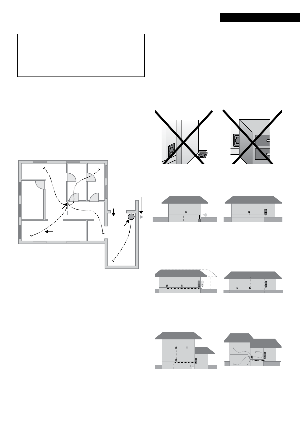
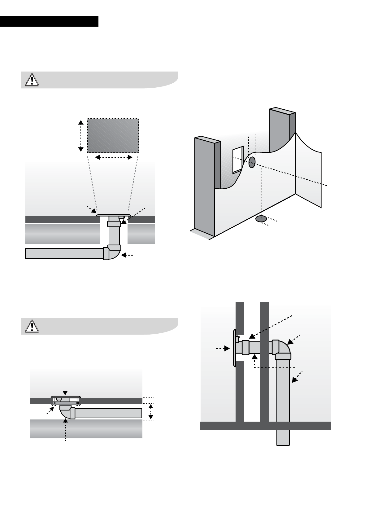
Wall inlet valves can be placed in the wall or in the floor. Place the inlets
preferably so that you can reach every corner of the room with a vacuum
hose that is 27 to 33 feet long (8m to 10m). There is a utility valve in the
power unit, which allows you to conveniently clean the space where the
vacuum is located and close-by areas, thus eliminating the need to install
another inlet valve and tubing route.
Marking the Placement of the Inlet Valves
Mark the installation points of the inlet valves in the layout drawings using
wire of the same length as the actual vacuum hose. When using drawings
scaled 1:1000 the wire length is 3 1/4” (8 cm), and when using drawings
scaled 1:50 the wire length is 6 1/2” (16 cm). Suitable places for inlet
valves are entrance halls, hallways, etc.
door
wall
valve
wall
valve
Floor
valve
Typical Installation Examples
power unit exhaust
pipe
wall valve
hose coverage
power unit
Tubing System Design
The main principle for designing the layout of the tubing system is to
keep it as short as possible. This will give the highest possible vacuum
performance. However, the main tube can be routed in different ways.
The outside diameter of the tubing system is 2” (50.08mm) and is 2 1/8”
(56mm) at the extension. The through-holes in the walls must be 2 3/16”
to 2 1/2” (55mm to 60mm) in diameter so that the extension and the lowvoltage cable can also go through the opening. The minimum diameter of
the exhaust tube is 2 1/8” (56mm).
New One-Story Houses
The horizontal main tube is placed in the under-house crawl space or in
the attic. In the under-house crawl space, the tubing should be insulated.
Tubes to the inlet valves are routed in the partition walls or between
secondary spaces, such as closets. In a cold attic, the tubes should be
covered with insulation in order to avoid condensation.
In a typical house only two inlet valves are needed. In such cases, the
utility valve of the power unit can
be used for cleaning the basement
because it often covers the whole
basement area.
In this example, the main tube has
been routed under the house. However, the tube in the under-house
crawl space should be insulated to
avoid condensation.
In the house of the same size, the
power unit is in the garage, where
the utility valve serves as a third
inlet valve allowing you to clean
your car, for example.
In this example, the simplest
solution is to route the tubing in
the attic. If the space is cold, the
main tube should be insulated.
Two- or Multi-Story Houses
The main tube is placed in the under-house crawl space, attic, closet,
between walls, etc.
Existing Houses
The main tube can be installed on the surface in existing secondary
spaces, such as a garage or storage room. The tube can also be routed
through the attic and then vertically inside the partition walls and closets
all the way to the inlet valves. A lowered ceiling and closet footings can
also be used for routing of the tubes.
The whole floor area can often be
vacuumed from one single inlet valve. The light, broken line indicates
an alternative installation type.
It is recommended to place the
inlet valves in between different
levels. In such cases, you can easily clean two levels from one inlet
valve. The power unit is placed in
the storage room.
Page 4
4 electrolux installation manual
Installation of the Wall Inlet Valves
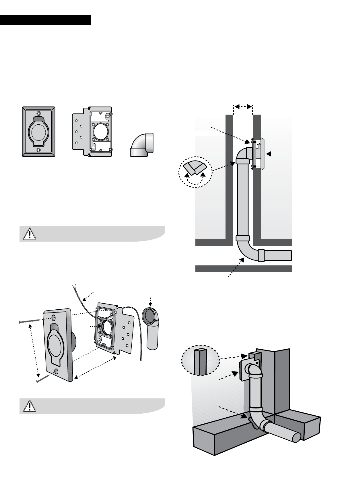
For the installation, you will usually need the following parts:
Inlet valve
Mounting bracket
90° elbow
Wall Installation of the Inlet Valve
A typical wall inlet valve installation is shown in the figure on the right.
A 90° inlet elbow is used in the wall installation to prevent long objects
entering into the tubing system, protecting it against blockages.
A 90° steep elbow can be fitted in two different ways. In practice, the
partition wall can be as narrow as 2 3/4” (65mm).
Note! A 90° inlet elbow must not be installed anywhere else in the tubing
system.
mounting bracket
choose the best angle
of the 90 ° inlet elbow
so that it fits best in
the surrounding space
open cavity
min. 2 3/4”
(65 mm)
wall
inlet valve
wall
floor
If the thickness of the wall board is more than 1” (25mm), you can reach
the mounting bracket by using an extension tube.
low voltage cable
mounting bracket
inlet vavle
long screw
seal
1/4”- 1”
(5–25 mm)
short screw
Note! When installing the short version of the 90° inlet elbow, use
short screws so that they do not extend into the tube.
90° elbow
90° sweep elbow
If the Structures of the House Prevent Tubing Routing
This can be avoided by making slots as shown in the figure below.
Supporting structural elements of the house should not be slotted. If you
cannot attach the mounting bracket properly to the batten wall, you can
install a separate mounting board.
pipe
mounting board
mounting bracket
sweep elbow
wall
Page 5
electrolux installation manual
5
2 3/8” (
60 mm)
Thread the low voltage cable through the slot
in the mounting bracket
low voltage
cable
4 3/4” (110 mm)
2 1/4”-2 1/2”
(57–62 mm)
Inlet Hole
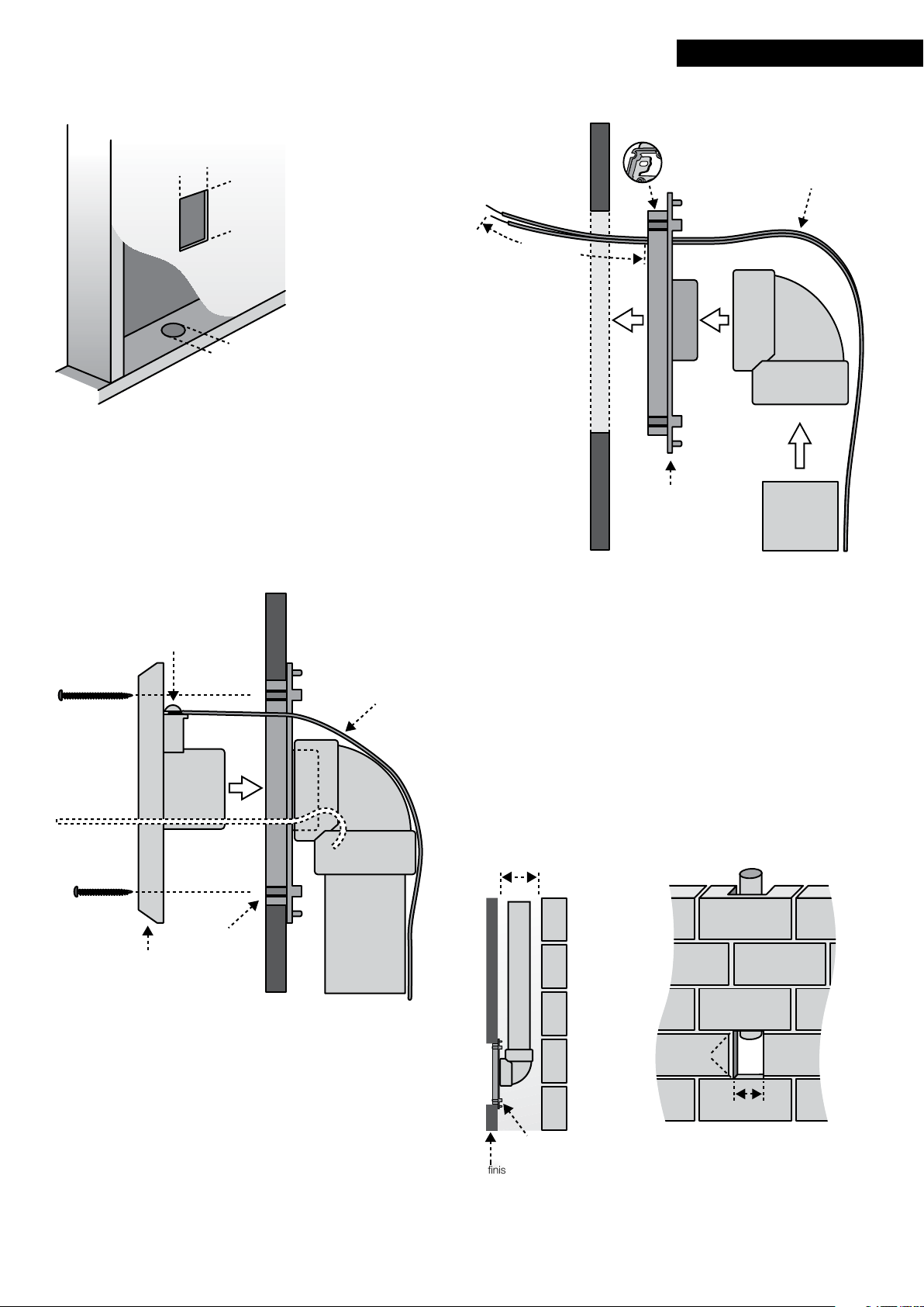
Make a hole in the board material for the inlet valve as shown in the figure.
The size of the rectangular opening should be 2 3/8” x 4 3/4” (60mm x
110mm). In existing houses where tubes are routed underneath, a hole can
be drilled for the tube using a guide hole as a template. Glue the 90° inlet
elbow onto the sleeve of the mounting bracket. Leave a gap of approximately 5/8” (15cm) for the low-voltage cable to be connected to the inlet
valve. Then the dust tube is glued into the inlet elbow.
Do not disconnect the mounting screws
completely. Loosen them enough to fit
the low voltage cable around them and
then tighten.
long screw
low voltage cable
min. 5/8” (15 cm)
90° elbow
mounting
bracket
pipe
wall
Installation in a Brick or Concrete Wall
When installing the inlet valve, sink the pipes, the inlet elbow, and the
mounting bracket in the wall so that the highest surface of the mounting
bracket is approximately 1/4” (5mm) deeper than the final inner surface.
For the tubing system, make a 3 1/8” x 3 1/8” (80mm x 80mm) channel
in the brick or concrete wall independent of the final thickness of the wall.
The tubing installation must be sturdy enough so that tubes and parts
do not move out of their positions later during the installation work. It is
recommended to cover the opening of the inlet valve to protect it from cast
material.
hook
90° elbow
short screw
mounting bracket
inlet vavle
wall
pipe
Strip off approximately 1” (2cm to 3cm) of the insulation from the end
of the low-voltage cable. Roll the end of the cable two turns around the
screws in the inlet valve and tighten the screws.
Screw the inlet valve into the mounting bracket and make sure that the
screw does not extend through the tube. If necessary, use shorter screws.
In a complete wall structure, the mounting bracket is held in place by a
hook as shown in the figure.
3 1/8” (80 mm)
wall mounting
bracket
finished wall surface
4 3/4”
(110 mm)
2 3/8”
(60 mm)
The tube can also be installed block / brick
wall with the rear side. In this case, the wall
is made imurasiaa for a picture with the hole.
Page 6
6 electrolux installation manual
Floor Installation of the Inlet Valve
This is usually the only possible installation method in existing houses.
Note! When installing the inlet valve and tubing system in the floor, make
sure that long sticks etc. do not to fall into the tubing.
floor installation hole
2 1/4” (55 mm)
2 3/4” (70 mm)
floor inlet valve
floor
floor insulation
tubing
floor installation with
extension
Installation in a Closet Wall
Choose a location and make a 2 1/8” x 2 3/4” (55mm x 70mm) opening
for the inlet valve. For the tube, a 2 3/8” (60mm) diameter hole is needed.
Drill a hole for the tube also in the floor of the closet. Cut the tube to the
proper length and glue it into the rebuilding sleeve.
interior wall
2 3/8”
(60 mm)
2 1/4”
(55 mm)
2 3/4”
(70 mm)
closet floor
closet wall
2 1/4” - 2 1/2”
(57–62 mm)
tubing
For a floor installation, it is recommended to use the method shown in the
figure, if applicable. It is the same as for the wall installation. The 90° inlet
elbow prevents long objects from accessing the tubing system. For this
method to be successful, the allowance under the floor should be at least
2 2/3” (65mm).
For floor installation, it is possible to use the floor sleeve or rebuilding sleeve. In such cases, the mounting bracket is not needed.
floor inlet valve
floor
mounting bracket
pipe 2 3/4”
floor insulation
90° elbow
1/4” - 1”
(5–25 mm)
(65 mm)
Insert the tube into the round hole with the floor sleeve/rebuilding sleeve
first so that it extends through the outer wall of the closet. Mount the inlet
valve in the rebuilding sleeve. Measure and cut the tube to the proper
length so that it reaches with the inlet elbow to the vertical tube.
wall installation
with extension
90° elbow
inlet valve
pipe
interior room
interior wall
closet wall
floor
90° elbow
Page 7
electrolux installation manual
7
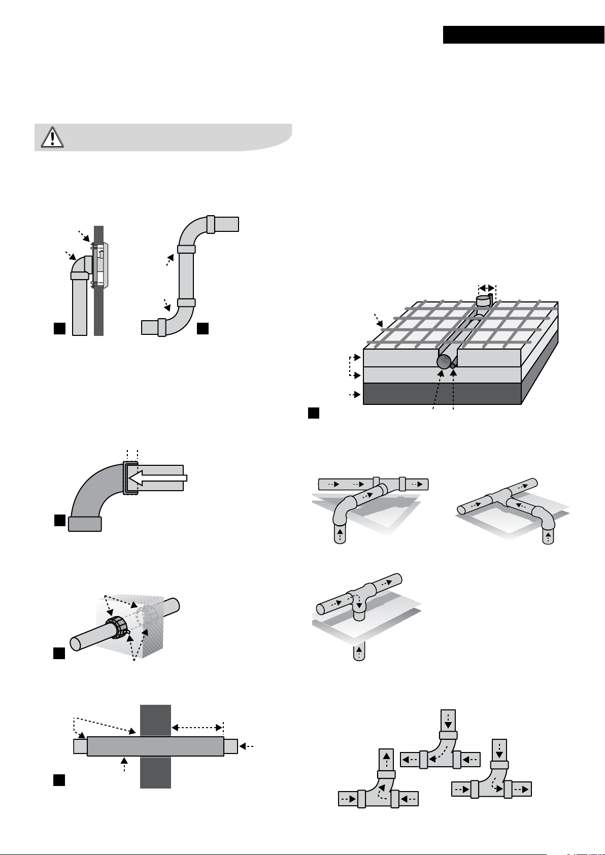
Tubing System Installation
Begin the main tube installation with the farthest inlet valve and place the
tubes temporarily at first. Do not glue the joints yet until you have made
sure that the tubing routing is correct. The glue will dry quickly; therefore,
Important notes for installation!
1) The 90° inlet elbow may be installed only together with the mounting
bracket and the inlet valve. Anywhere else in the tubing system, 90°
sweep elbows and 45° elbows should be used. (Fig. A and B)
mounting bracket
90° elbow
90°
sweep
elbow
the joints have to be fitted right after applying the glue.
When measuring the tubes, take into account that the tube goes approximately 2/3” (18mm) into the sleeve and approximately 7/8” (20mm) into
the extension tube.
The tubing system can also be installed in a floor that will be concrete
casted later on (Fig. F). In such cases, the low-voltage cable must be
protected by a conduit pipe. The conduit pipe should be attached to the
vacuum tube or the casting net. For the vacuum tube, the routing channel
has to be 2” wide (51mm). The ends of the vacuum tubes and the conduit pipes should be plugged before concrete casting.
wire mesh
2” (51 mm)
A
B
2) Tubes are cut straight so that the cutting line is not slanted. Use a miter
saw if possible. Cut edges can be finished with a knife (to remove burrs).
3) For tubing joints, use suitable PVC glue to make the fittings secure and
tight. Apply a thin and even layer of glue only to the end of the tube – not
to the sleeve. This will prevent the glue from overflowing to the end face
of the tubing. Close the glue can carefully immediately after use and make
sure to have adequate ventilation during installation. Avoid inhaling glue
vapors. Insert the tube all the way into the sleeve while turning it at the
same time (Fig. C).
min. 3/4” (18 mm)
C
push the pipe completely into the fitting
4) The inlet is made through the fire wall according to Fig.figure E or by
using a 2” (50mm) diameter fire cuff (Fig. D). Check the inlet with a fire
authority.
fire stopping pipe
collars
concrete
sand
F
Installation Examples
correct
vacuum pipe electrical tube
correct
vacuum pipe
D
protects the combustible
building material
steel protective sleeve
E
min. 1/ 16” (2 mm)
wall
pipe collars are attached
to the wall
wall
min. 7 7/8”
(200 mm)
incorrect
correct
vacuum pipe
incorrect
incorrect
Page 8
8 electrolux installation manual
Notes!
Minimize Condensation
If the tubing installation is carried out in winter, a large amount of condensation may be generated. To reduce the amount of condensation, close all pipe holes and inlet openings using duct tape during installation. Before starting to use the central vacuum system for the first time, let the system vacuum and circulate fresh air for a few minutes, and
make sure that there is no water in the dust container. If there is water in the container, drain it and continue vacuuming until no more water is accumulated.
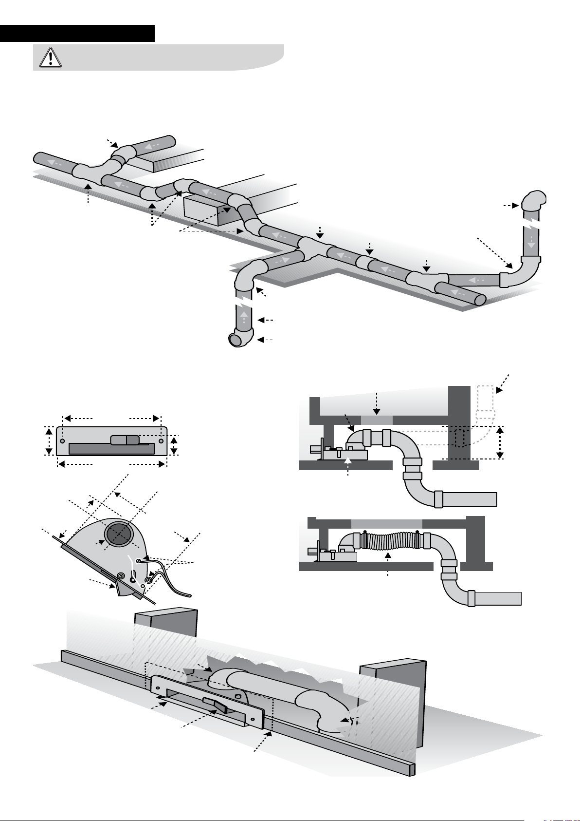
45° elbow
Example showing piping with different types of
connections.
90° sweep T
45° elbow
90° sweep elbow
VacPan Installation
VacPan is most useful in the kitchen, in the hallway, etc. It can be easily installed, for
example, in a cabinet footing or next to the wall.
VacPan dimensions:
2 1/4”
(53 mm)
7 1/2”
(190 mm)
8 5/8”
(215 mm)
2 3/4”
(70 mm)
1 9/16”
(40 mm)
90° sweep T
pipe
90° elbow
Example of a VacPan
installed in a cabinet.
floor
90° elbow
VacPan
pipe connector
maintenance access
required
cabinet floor
45° single Y
90° elbow
90° sweep elbow
piping may exit
the cabinet and go
vertical
wall
min. 4”
(100 mm)
2 3/4”
(70 mm)
4”
(99 mm)
DO NOT
switch
GLUE
front edge is flush
with floor surface
central vacuum
6 1/2”
(165 mm)
starts when
switch is
activated
90° elbow
low voltage
connections
cover plate is
additonal
available
installation using flexible
vacuum tube
90° sweep
elbow
wall
floor
floor
Page 9
electrolux installation manual
9
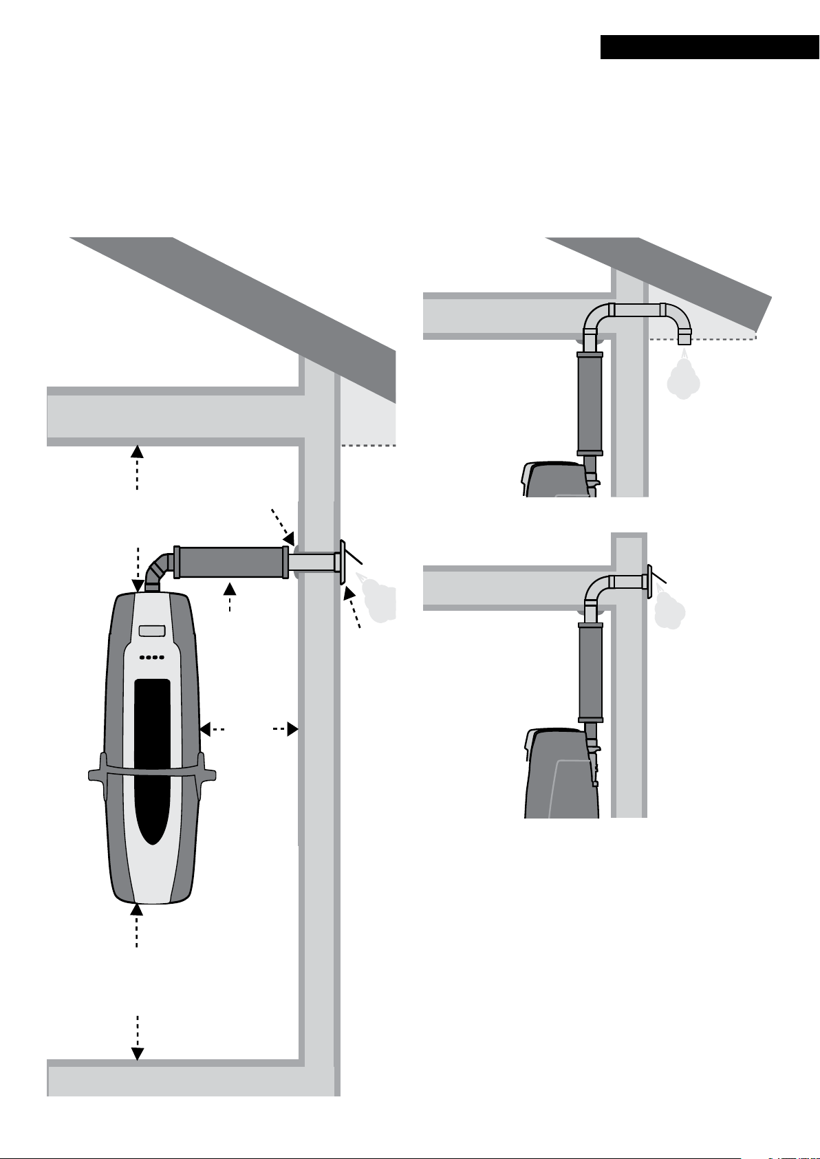
Exhaust Blow-Out
Because the exhaust tube must be as short as possible, it is
recommended to place the power unit as close to an outside wall as
possible. Shown below are examples indicating how to install the exhaust
tube. The exhaust muffler can be installed upwards, downwards, as well
as horizontally.
Min. 30cm
(12”)
ceiling
insulation
additional
silencer
roof
ceiling
exterior wall
exterior wall
ceiling
exhaust valve
Min. 70cm
(27.5”)
Min. 30cm
(12”)
exterior wall
Page 10
10 electrolux installation manual
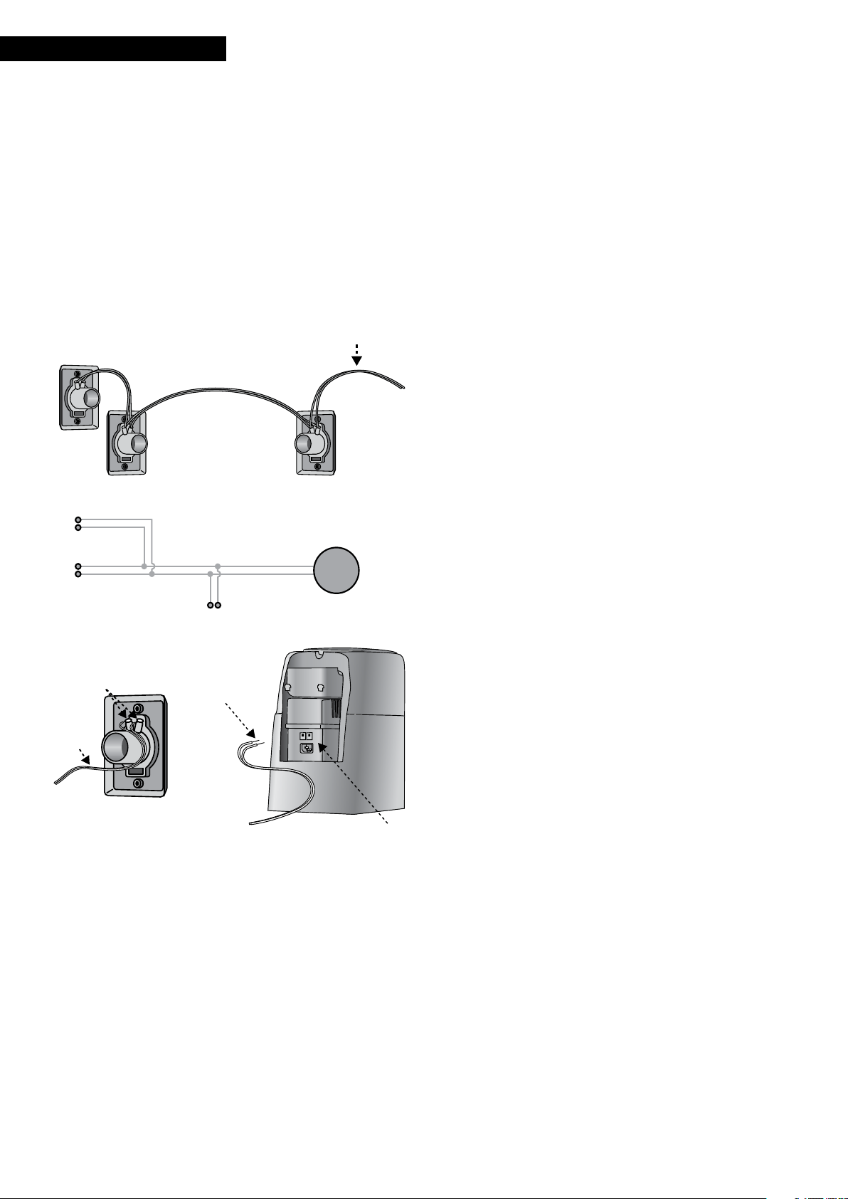
Electrical ConnectionLow-Voltage Cable
To power on the central vacuum system, a 24V low-voltage cable is
routed to each inlet valve. Parallel connection is made according to the
figure below.
low voltage
cable
inlet valve1
inlet vavles conneted
in series
inlet valve 2 inlet valve 3
low voltage circuit diagram
low voltage cable
contact pins
low voltage
cable
inlet valve
It is recommended that the low-voltage cable be installed in a conduit
pipe, and this is absolutely necessary when cables are to be hidden in
cast concrete. If the cable becomes defective, it is also much easier
to change it afterwards. In these installations, only certified electrical
components may be used.
with stripped ends
low voltage
connetion terminals
The power unit is connected to an electrical outlet. If there is no outlet
nearby, an electrician will carry out installation.
All the high-voltage connections are under the turbine cover. Only an
electrician is allowed to open the cover.
Page 11
Electrolux Central Vacuum Systems
1700 West Second Street
Webster City, IA 50595
United States of America
www.electroluxcentralvac.com
The Thoughtful Design Innovator.
Do you remember the last time you opened a gift that made you say, “Oh!
How did you know? That’s exactly what I wanted!” That’s the kind of feeling
that we at Electrolux seek to evoke in everyone who chooses or uses one
of our products. We devote time, knowledge, and a great deal of thought to
anticipating and creating the kind of appliances that our customers really need
and want.
This kind of thoughtful care means innovating with insight. Not design for
design’s sake, but design for the user’s sake. For us, thoughtful design means
making appliances easier to use and tasks more enjoyable to perform, freeing
our customers to experience the ultimate 21st century luxury: ease of mind.
Our aim is to make this ease of mind more available to more people in more
parts of their everyday lives, all over the world.
The “Thinking of you” promise from Electrolux goes beyond meeting the needs
of today’s consumers. It also means we’re committed to making appliances
safe for the environment—now and for future generations.
Electrolux. Thinking of you.
Share more of our thinking at www.electrolux.com
 Loading...