

Page 1
MODEL
AR 4100
AR 4090
USER MANUAL
Graphic project
VISUAL DIVISION
Milano
3
ELECTROLUX EUROCLEAN ITALIA SPA
Località Novella Terza 20070 Guardamiglio-Italy
Tele
p
hon nr. +39 377 451124 Fax nr. +39 377 51443
90E13SU
1
st
EDITION
K
Page 2
INDEX
INTRODUCTION/GENERAL INSTRUCTION .........................1-2
TECHNICAL SPECIFICATION .................................................3
DESCRIPTION OF CONTROLS............................................4-5
PREPARING A NEW MACHINE..........................................6-7
PREPARATION FOR USE .................................................8-11
USING THE MACHINE ..................................................12-16
AUTOMATIC CHANGING OF BRUSHES...............................17
USER MAINTENANCE...................................................18-20
EMERGENCY AND AUXILIARY CONTROLS..........................21
ACCESSORIES ...................................................................22
ERROR CODE MEANINGS..................................................23
page
Page 3

INTRODUCTION
This manual is a guide to the efficient use of the machine and also contains practical information
concerning the operational adjustments and user maintenance of your machine. Your machine
has been designed and constructed to ensure maximum performance and ease of operation in
a wide variety of applications.
Before delivery, the machine has been tested in our factory and by our distributor to ensure that
it is delivered to you in perfect condition. To maintain the machine in this condition and
guarantee operation without problems, it is essential that the periodic maintenance operations
indicated in this manual are properly carried out. Before using the machine, carefully read this
manual and keep it within easy reach for your future reference. Indications of “LEFT” and
“RIGHT” are as seen from the operators position.
If you should need any further information concerning the machine, please do not hesitate to
contact either ELECTROLUX EUROCLEAN or your local distributor.
MODIFICATIONS AND IMPROVEMENTS
Electrolux Euroclean aim toward continuous improvement of its machines and reserves the right
to carry out modifications and improvements whenever necessary without being obliged to
update machines which have been sold previously.
SAFETY
You too can avoid accidents.
No accident prevention programme is effective without the total co-operation of the person
directly responsible for the operation of the machine. The majority of accidents which may occur
either during work or transferring the machine from site to site are caused by the nonobservance of the most elementary safety rules. An alert and cautions operator is the best
guarantee against accidents and is more effective than any other part of an accident prevention
programme.
The machine must be switched off and disconnected from its battery any servicing or adjustment
of an operational part is carried out. Ensure that any assistant is clear of the machine and that
protective covers are closed before switching on.
INTRODUCTION/GENERAL INSTRUCTION
1
Page 4
INTRODUCTION/GENERAL INSTRUCTION
23
2
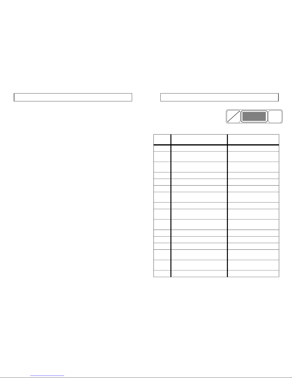
ERROR CODE MEANINGS
If the error code indicator flashes a problem
has arisen or is imminent. Read the code in
the display to recognise the problem and
decide what action is necessary.
CODICE
ERRORE
PROBLEM POSSIBLE CAUSE
300 High traction wheel brake temperature Check brake pad drag
301 Traction shut-off due to wheel brake
high temperature
-Ditto-
302 Traction motor output transistor/s
faulty
Check for motor fault before
replacing P.C.B.
303 High current in traction circuit Check overload in traction
304 Traction output transistors = 85° C -Ditto-
305 Traction output transistors = 95° C -Ditto-
306 Traction output transistors = 105° C
(shut-off)
-Ditto-
307 Faulty accelerator potentiometer Replace potentiometer
308 Broken accelerator potentiometer
cable
Replace cable
402 Brush motors output transistor/s faulty Check for motor fault before
replacing P.C.B.
403 High current in brush motor circuit Check overload in brush motors
404 Brush motors output transistors = 85°C -Ditto-
405 Brush motors output transistors = 95°C -Ditto-
406 Brush motors output transistors = 85°C
(shut-off)
-Ditto-
602 Brush motors output transistor/s faulty Check for motor fault before
replacing P.C.B.
700 24v supply missing Check fuses
H
P
ERROR
CODE
GENERAL RULES OF SAFETY
The information below must be followed carefully in order to avoid injury to the operator, or
damage to the machine.
- Read the labels carefully on the machine, do not cover them for any reason and replace them
immediately if damaged.
- Do not mix different detergents to avoid the possible production of dangerous gasses.
- Do not place any liquid containers on the machine.
- The storage temperature should be between 25°c and 55°c.
- The operating temperature should be between 0°c and 40°c.
- Humidity should be between 30% and 95%.
- Do not use the machine in explosive atmospheres.
- Do not use the machine as means of transport.
- Do not use acid solutions which could damage the machine.
- Avoid operating the brushes when the machine is standing still, in order to prevent floor
damage.
- Do not pick up inflammable liquids with the squeegee.
- In case of fire, use a powder extinguisher. Do not use water.
- Avoid shelving or scaffolding, where there is danger of falling objects.
- Adapt the operational speed to the surface adhesion conditions.
- Do not allow the machine to tip sideways along a gradient greater than 2% in order to avoid
conditions of instability (2% max).
- Mark out the cleaning area with “WET FLOOR” warning signs, particularly in public areas.
- If the machine does not work properly, check by conducting simple maintenance procedures.
Otherwise, it is better to ask for technical service.
- Where spare parts are required contact ELECTROLUX EUROCLEAN or a local distributor for
genuine original parts, or ask for on site technical service.
- Remove the battery connector before carrying out any maintenance on the machine.
- Do not remove items which require the use of tools to be removed.
- Do not wash the machine with direct water jets or with high water pressure or with corrosive
detergents.
- Every 200 working hours have a machine maintenance check by a technical service
department.
- The machine should not be abandoned, because of the presence of toxic-harmful materials
(batteries, oil etc). This disposal must be subject to the regulations which provide for its
scrapping in appropriate centres.
The machine does not cause any harmful vibration.
Page 5
TECHNICAL SPECIFICATIONACCESSORIES
Depending on the country in wich the machine is
supplied three options are possible:
1. Battery supplied and fitted, filled with acid and
ready for use.
2. Battery supplied and fitted but dry.
3. Battery obtainable locally by customer.
Battery charges if required, are supplied matched
to battery capacity and depending on the country
in which it will be used, at different voltages and
frequencies.
A range of brushes and pads are available
together with pad holders for use on various types
of floors.
Ask your nearest distributor for a list of the
complete range and advice on their use.
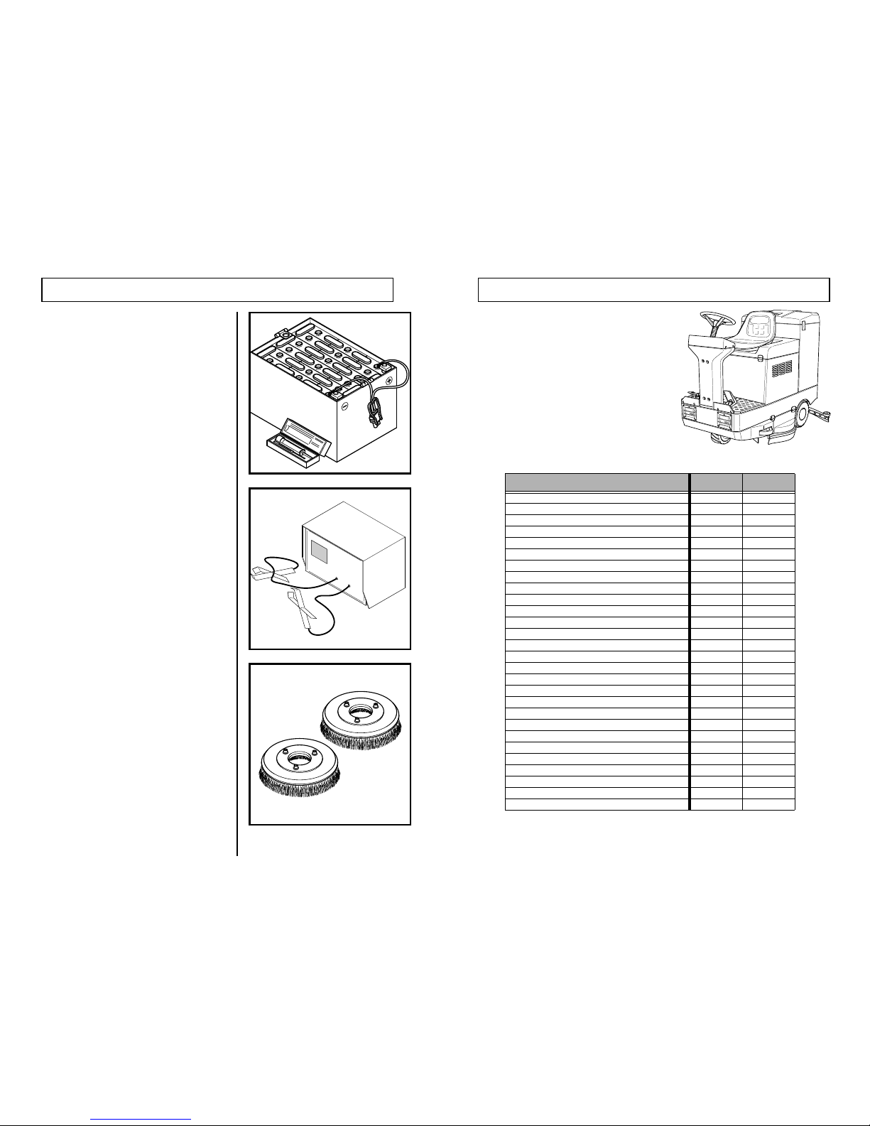
TECHNICAL SPECIFICATION
MODELS
AR 4090
AR 4100
Working width (mm)
840 1000
Width of squeegee (mm)
1130 1280
No. of brushes
22
Automatic change of brushes
Yes Yes
Brush diameter (mm)
430 500
Brush speed (rpm)
200 200
Brush motors (watts)
1000 1300
Brush pressure (Kg)
10-80 10-90
Clean liquid tank - Nett (ltr)
150 175
Recovery tank - Nett (ltr)
160 190
Vacuum motor (watts)
750 750
Vacuum motor control
electronic electronic
Vacuum motor type
3 stage 3 stage
Vacuum depression (mm/H
2
O)
1650 1650
Battery condition meter
Yes Yes
Electronics error codes
Yes Yes
Traction control
electronic electronic
Maximum gradient
16% 16%
Traction motor (watts)
1000 1000
Forward speed (km/h) 1-2-3 speed
2-4-6 2-4-6
Reverse speed (km/h)
33
Drive wheel diameter (mm)
250 250
Trail wheel diameter (mm)
2x300 2x300
Operating voltage
36 36
Lenght (mm)
1580 1580
Width (mm)
860 1030
Height (mm)
1280 1280
Weight (kg)
265 300
322
Page 6
214
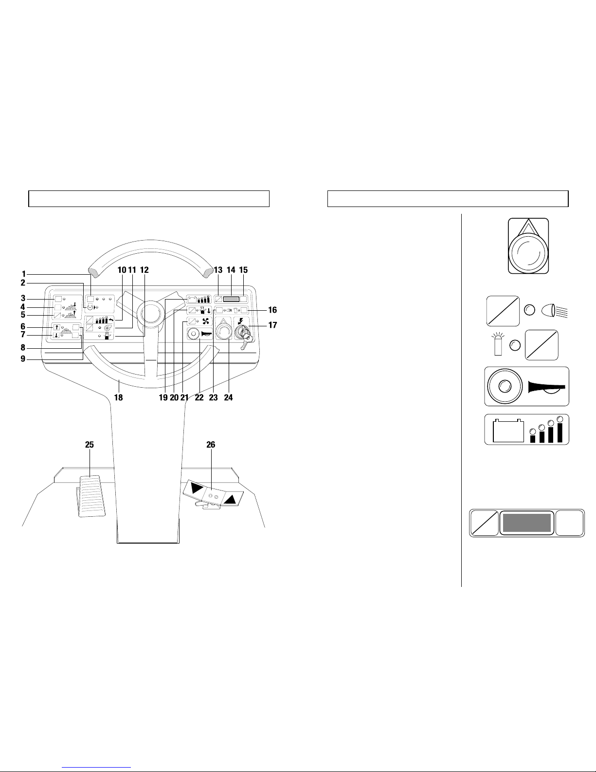
DESCRIPTION OF CONTROLS
C
1
2
3
ON
OVERLOAD
+
-
+
-
ON
CLICK-OFF
SPEED
CLICK-ON
OFF
ON
OFF
O
N
O
FF
ON
H
P
O
FF
ON
O
FF
O
N
O
FF
ERROR
CODE
EMERGENCY STOP BUTTON
In the event of an emergency hit the button, all
controls are killed and the machine stops.
To reset, turn in the direction of the arrow to
release the button.
Press the headlight ON/OFF push to switch on,
press again to switch off.
Press the beacon ON/OFF push to switch on,
press again to switch off.
NOTE: The beacon is an optional extra fitting.
Press the button to sound the warning horn.
The battery condition indicator shows the charge
state of the battery.
If the red indicator lights continuously then the
machine will shortly stop because the battery has
during use to a predetermined level beyond which
battery damage will result. All operation will stop
except traction and the recovery tank discharge
pump, so allowing you to empty the recovery tank
and return to the charging point.
The display normally shows the operating value of
the brush pressure. Pressing the H/P button will
display the total hours the machine has run,
pressing it again will show the additional minutes.
After a short time the display will revert to the
brush pressure indication.
EMERGENCY AND AUXILIARY CONTROLS
ON
OFF
ON
OFF
+
_
H
P
ERROR
CODE
Page 7
520
USER MAINTENANCE
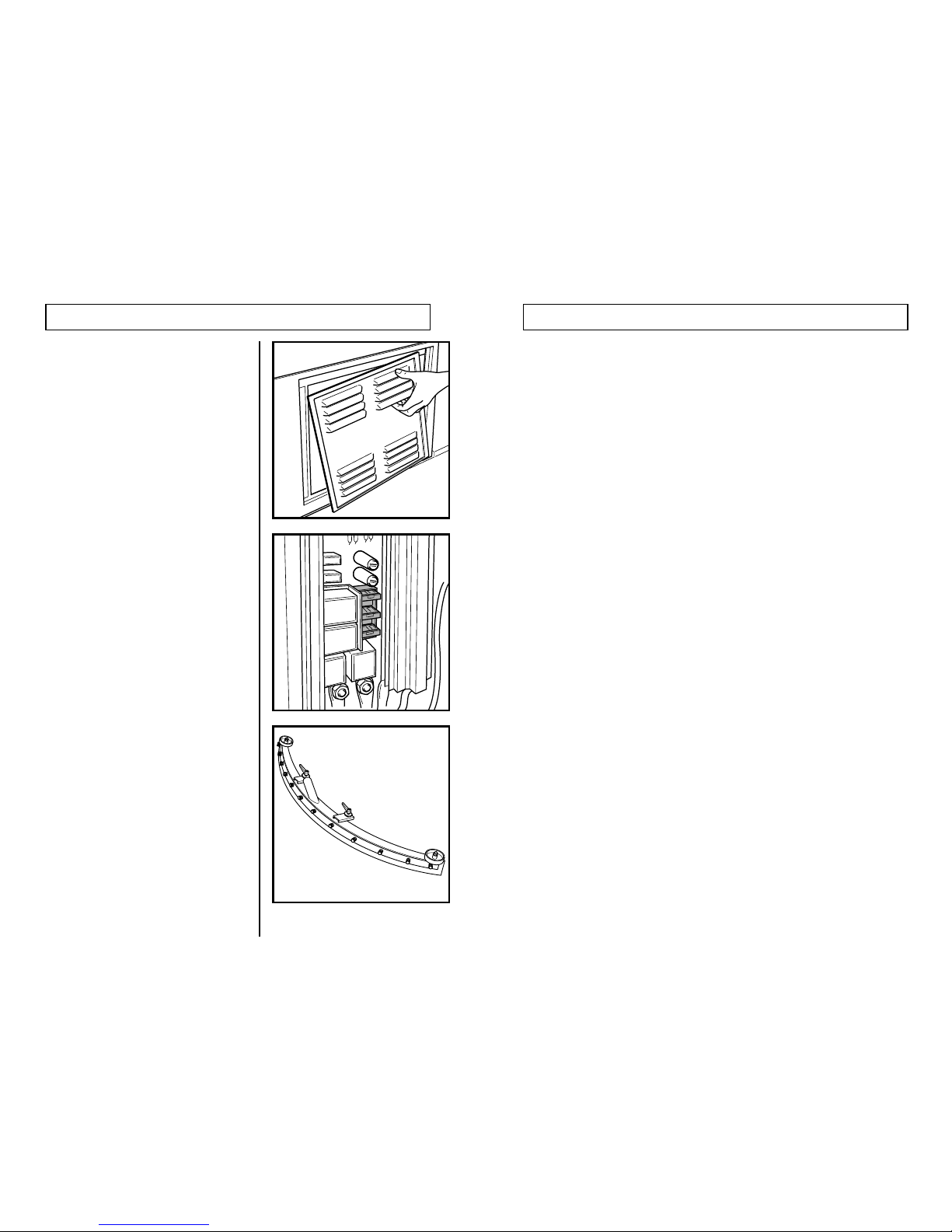
WARNING: The machine must be
switched off and the battery unplugged.
Remove the inner plastic cover to gain access to
the electrical panel.
Check and replace a blown fuse with one of a
similar value if necessary.
Reassemble the covers in reverse order.
If the drying results are poor or leaving streaks
then remove and clean the squeegee.
Check that the lips are not torn or damaged and
that they are not “feather edged”, if they are they
should be replaced.
DESCRIPTION OF CONTROLS
1
- Forward speed selector
2
- Traction motor overload indicator
3
- Automatic brush changing selector
4
- Brush unlock
5
- Brush drive ON/OFF
6
- Raise brushes
7
- Lower brushes
8
- Increase brush pressure
9
- Decrease brush pressure
10
- Clean liquid flow selector
11
- Clean liquid boost pump ON/OFF
12
- Recovery tank full indicator
13
- Display data selector
14
- Data display (Brush pressure, Hours, Minutes, Error codes.)
15
- Error code indicator
16
- Rotating beacon ON/OFF (Optional extra)
17
- Master key switch
18
- Steering wheel
19
- Battery condition indicator
20
- Recovery tank discharge pump ON/OFF
21
- Suction motor and squeegee lower/lift ON/OFF
22
- Horn push
23
- Headlights ON/OFF
24
- Emergency stop button (Turn in direction of arrow to release)
25
- Foot brake
26
- Forward/reverse traction accelerator
Note: Switches indicating ON/OFF require pushing once for ON to start
then pushing once again for OFF.
Page 8
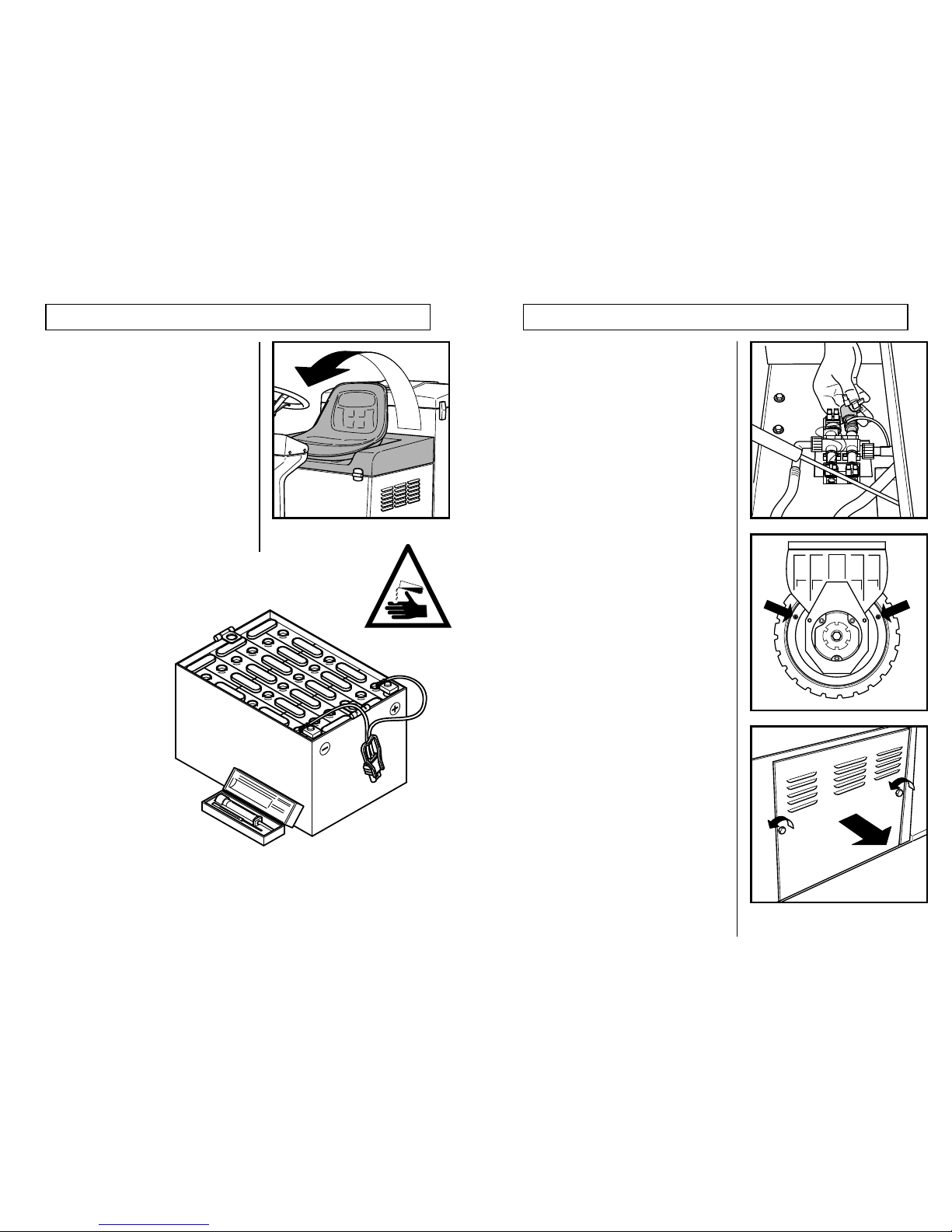
If a battery is fitted, unscrew one of the vent caps to determine if it is filled
with acid which covers the plates and separators.
1. If acid is present then all that is necessary is to
plug the battery connector into the
machine.
2. If the battery is supplied
without liquid, it must be filled
up with acid before it can be
used. Read the leaflet
supplied with the battery
about filling and
maintenance.
3. If no battery is supplied then
this will have to be purchased
separately and fitted. Cable
terminations for the battery take-offs
which will be supplied with the
battery, will have to be fitted to the
connector leads which are supplied with
the machine.
6 19
PREPARING A NEW MACHINE
The machine is battery operated.
Depending on the country in which the machine is
supplied three options are possible:
1. Battery supplied and fitted, filled with acid and
ready for use.
2. Battery supplied and fitted but dry.
3. Battery not supplied.
The battery compartment is under the seat. Lift the
seat upwards and over the steering wheel to see
which option applies with your machine.
WARNING: The machine must be
switched off and the battery unplugged.
Remove each solenoid assembly one at a time, by
pulling the two spade connectors away from the
unit then turn the coil through 90° and lift away
along the axis. Wash the rubber diaphragm
clean, wipe the seating with a damp cloth, then
reassemble in reverse order.
Repeat this operation with the other three valves.
Every 50 hours as seen from the run time display
on the panel, inject four pump strokes of
molybdenum gear grease from a high pressure
grease gun (the type used for cars) into each of
the greasing points of the traction wheel.
To gain access to the fuses, remove the right side
panel.
USER MAINTENANCE
Page 9
18 7
USER MAINTENANCE
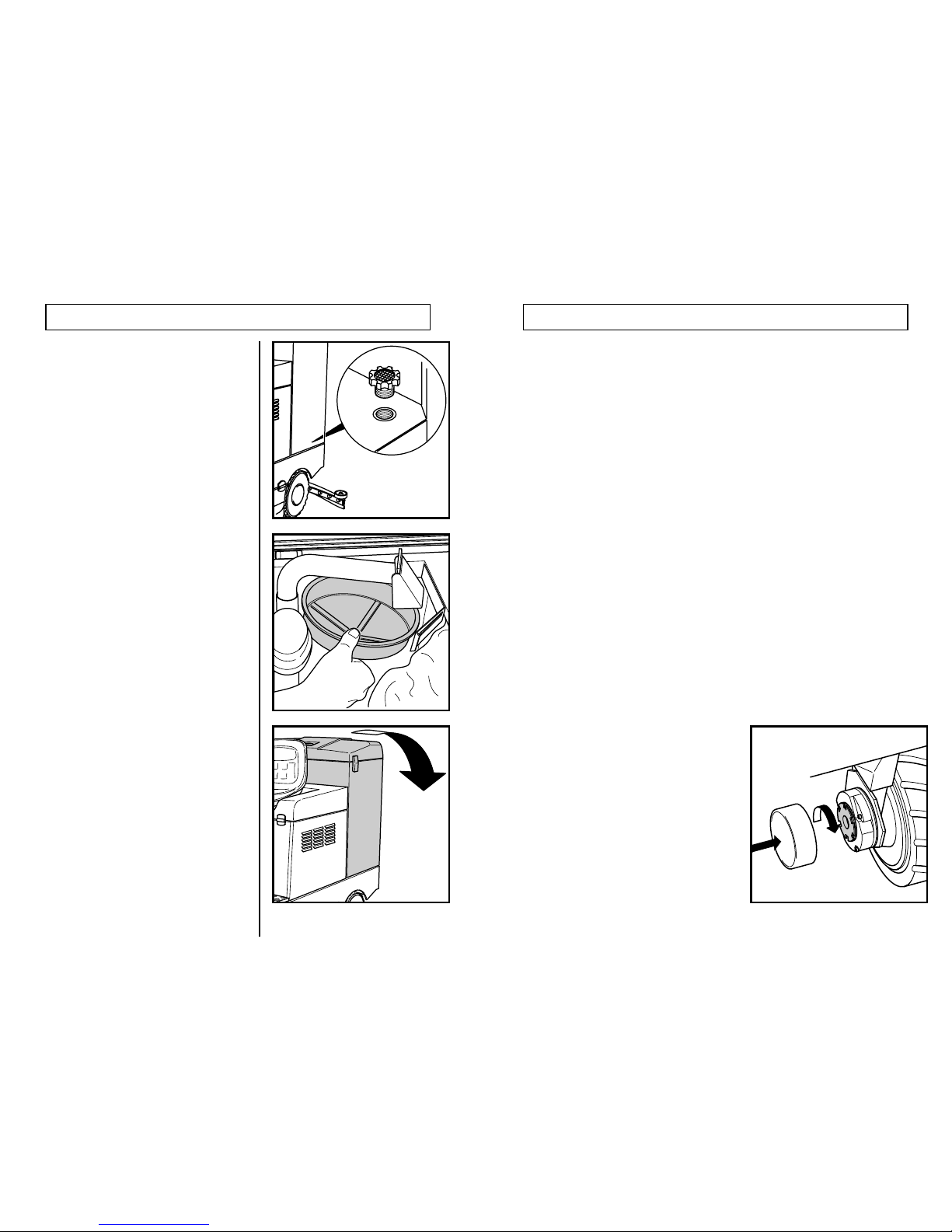
WARNING: The machine must be
switched off and the battery unplugged.
Unscrew the clean tank filter and scrub with a stiff
brush to remove all accumulated foreign matter
and lime build-up.
When the recovery tank is emptied lift out the
filter, remove any accumulated rubbish and wash
under running water.
If the liquid flow to the brushes deteriorates then
the solenoid valve diaphragms should be
cleaned. To gain access to these tip back the
empty tank unit to its fullest extent (it is limited by a
supporting gas spring).
PREPARING A NEW MACHINE
Take special care when handling acid as it is corrosive, if it should come into contact with skin
or eyes, wash abundantly with water and consult a doctor.
The batteries should be charged in a well ventilated area with the seat raised, using the charger
supplied or one which matches the battery capacity.
For charging and maintenance operations on the batte ry see the instruction leaflets of both the
battery and the charger.
It is recommended that battery specialists deal with the commissioning of new batteries.
BEFORE OPERATING THE MACHINE
The previously slackened magnetic brake must be set
for normal operation.
Screw in the brake tension plate clockwise until the
machine cannot move, turn on the key switch to
“ON”, then gently press the traction accelerator
pedal. The brake should be heard to snap “off” and
with further pressure on the pedal the machine will
move forward. The tension plate should be adjusted
so that from full speed the machine stops within 1.5
metres from the point the pedal is released.
When the braking distance has been set, fit the brake
cover to avoid the ingress of foreign matter.
Page 10
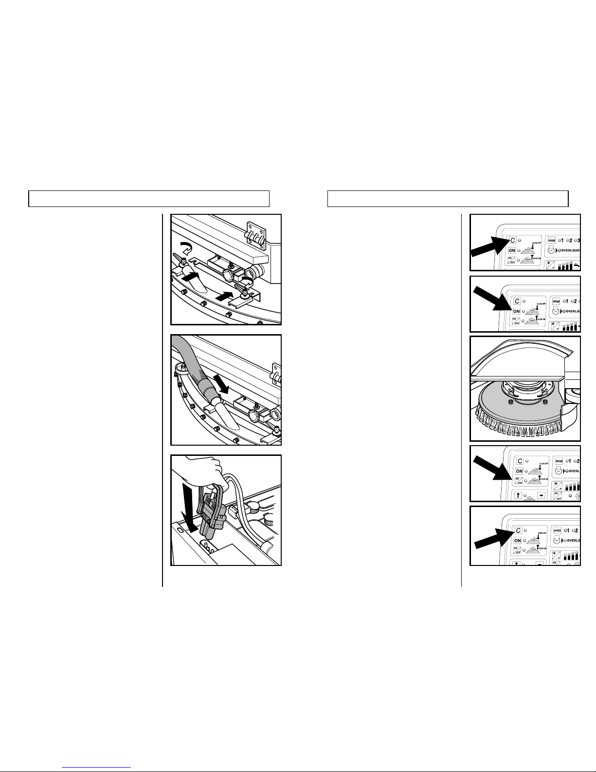
8
17
Attach the squeegee to its bracket at the rear of
the machine. Lock the hand nuts down tightly.
The bracket is slotted so that if the squeegee is
hooked around an object it will pull away from
the bracket instead of causing more serious
damage.
Push the hose cuff firmly over the squeegee spigot.
Open the battery cover and firmly push the
battery socket into the machine plug, as
illustrated.
PREPARATION FOR USE
Switch all functions off. Turn key-switch on.
Press the automatic brush change selector push
button.
Press the brush unlock push button and the
brushes will be heard to drop to the floor.
Open the brush doors.
Withdraw the unloaded brushes.
Replace with fresh brushes, ensuring they are
pushed fully against the location plate.
Press the brush loading push button, the motors
will start and pick up the brushes.
Wait until the motors stop, then press the brush
changing selector push button to return to normal
working.
AUTOMATIC CHANGING OF BRUSHES
Page 11
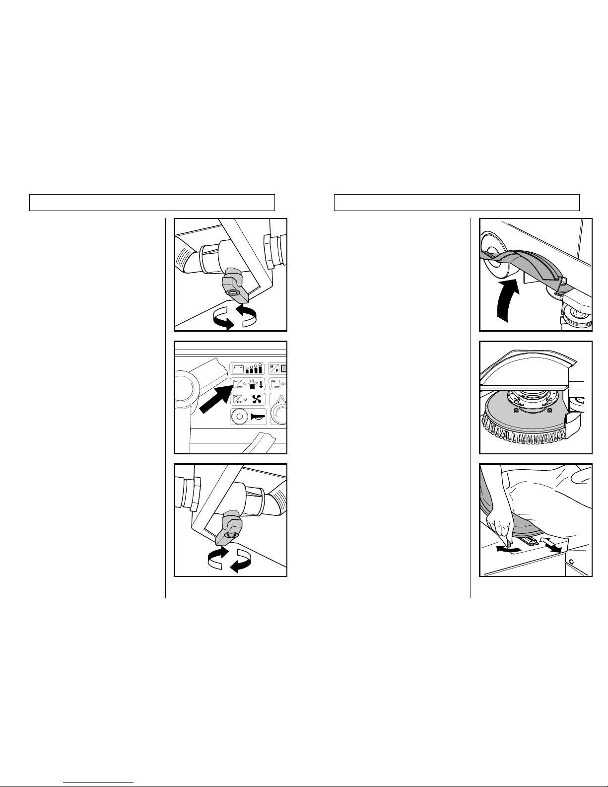
16 9
USING THE MACHINE
Open the valve by turning its lever in line with the
outlet.
To quickly empty the tank switch on the key-switch
then press the recovery tank discharge pump
ON/OFF push.
Press the push button again when the tank is
empty to switch the pump off.
If the task is completed it is advisable to also
empty the detergent tank to avoid system
blockages. The dump hose may be attached to its
valve and the valve turned on in the same manner
as for the recovery tank but can only be
discharged by gravity.
Open the brush doors located either side of the
machine.
Push a brush fully in to ensure that it sits against
the location plate, repeat the other side.
Sit in the seat and adjust by moving the lever to
the right as illustrated to unlock the seat slide.
Move the seat back or forward to a comfortable
position.
PREPARATION FOR USE
Page 12
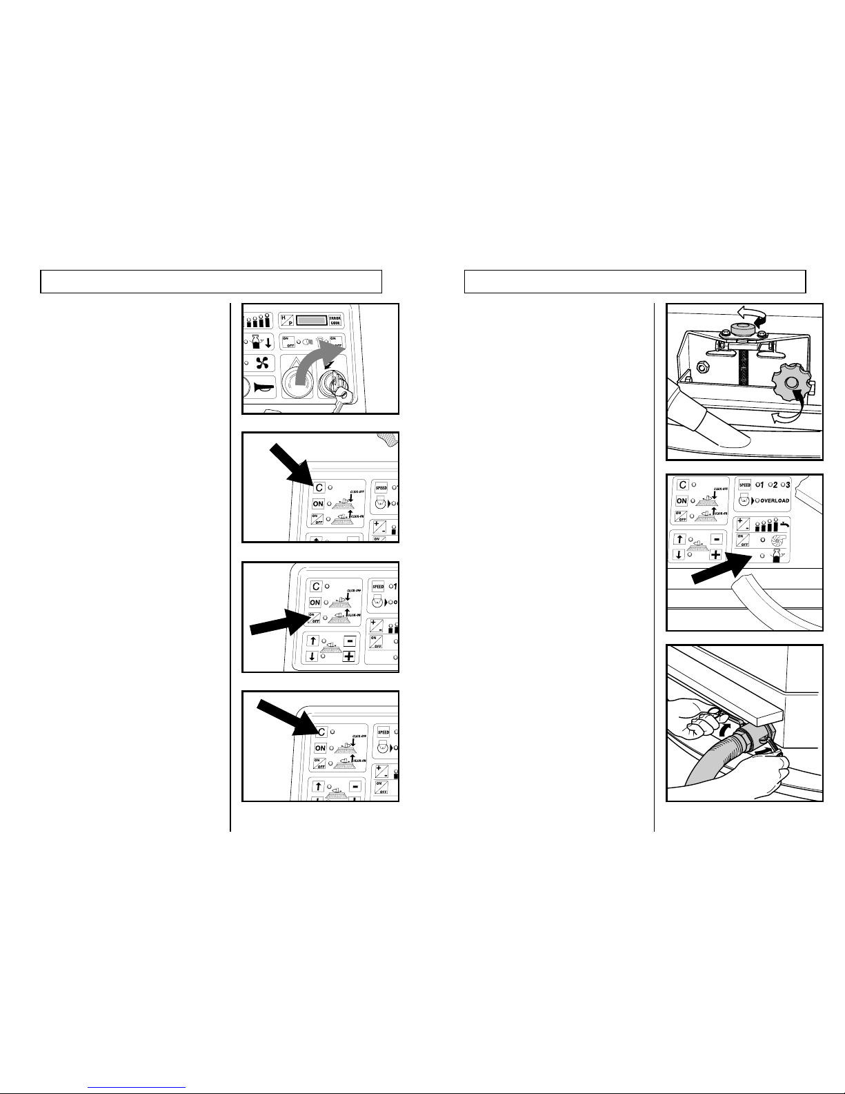
10
15
Insert the key and turn clockwise to turn the
machine “ON”.
Select the “Click-on” “Click-off” brush system by
pressing push marked C,
Press the lower push of the group of three marked
ON/OFF. This starts the brush motors rotating and
the scrubbing head winding down to engage the
brushes. When the brushes have engaged, the
scrubbing head then winds upwards to its rest
position.
Having mounted the brushes, now press the
button marked “C” again to exit the “Click-on”/
“Click-off” system.
PREPARATION FOR USE
The squeegee can be adjusted for pressure
against the floor by turning the lower of the two
plastic knobs just above the squeegee bracket.
The rake angle can be adjusted to make the
squeegee sit fully on the floor by adjustment of the
upper knob.
When the recovery tank becomes full an indicator
will start flashing on the panel, if this remains on
for longer than 5 seconds the suction motor will
switch off and the squeegee raise. It is now
necessary to empty the tank.
The recovery tank dump valve is situated at the
lower rear of the machine to which the dump hose
may be attached.
USING THE MACHINE
Page 13
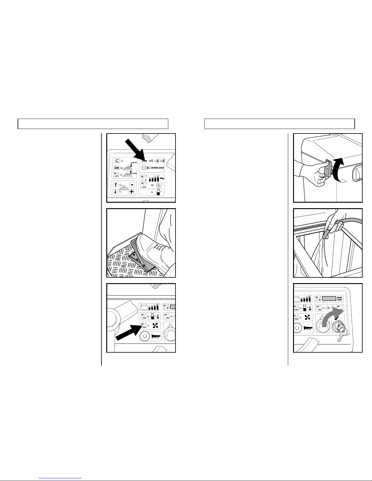
14 11
Press the speed button to select one of three
predetermined maximum speeds of 2, 4 or 6 km/
h (1.2, 2.5, or 5 mph) in the forward direction.
In reverse the speed is limited to 3 km/h (2 mph)
maximum.
The foot pedal at the left of the steering column is
the foot brake.
Press the suction motor ON/OFF push which also
automatically lowers the squeegee at the rear of
the machine. To raise the squeegee press the push
again, which also switches the suction motor off.
USING THE MACHINE
Release the tank lid locking clips at both sides of
the tank, then lift the lid towards the back of the
machine.
The tension of the locking clips is adjustable to
take up compression of the gasket.
Fill the clean liquid tank with water to within about
75mm. (3ins.) of the top. Add the detergent to the
water according to the instructions on its container
to obtain the correct dilution rate.
Always add the detergent to the water, NOT
water to detergent or you may find you have a
tank full of foam!
Close and lock down the tank lid.
Switch the machine on by turning the key switch
clockwise.
PREPARATION FOR USE
Page 14
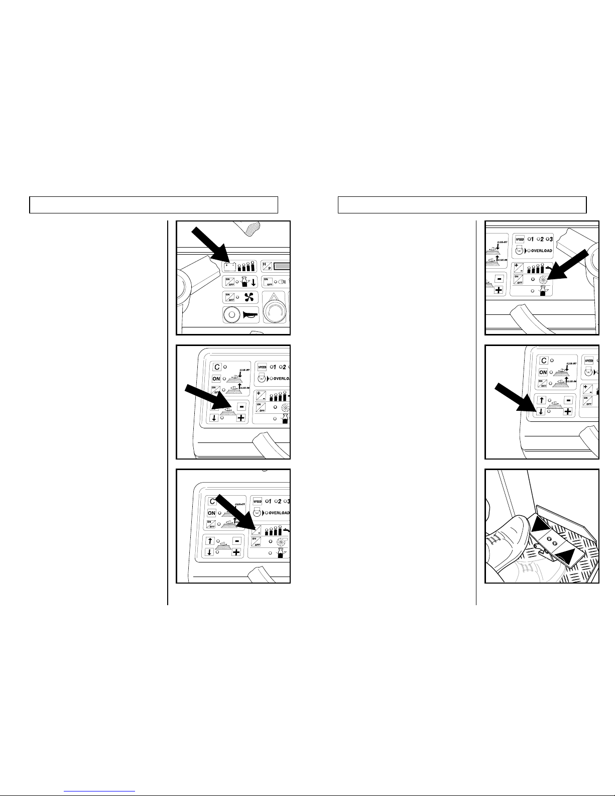
12 13
Whilst the machine is being used take note of the
battery condition indicator, if the red indicator
lights continuously then the machine will shortly
stop scrubbing because the battery has run down
during use to a predetermined level beyond which
battery damage will result. Scrubbing and drying
operations will stop, but traction and the recovery
tank discharge pump will still operate allowing
you to empty the tank and return to your charging
point.
Press the brush motor ON/OFF push button to
start the brushes.
Press “+” to increase or “-” to decrease the brush
pressure.
When the machine is positioned ready for
scrubbing, select the estimated amount of clean
liquid required by pressing the detergent flow
control ON/OFF push. An indicator will light
which can be increased in four steps for varying
the quantity of liquid delivered to the brushes.
NOTE that the liquid will be delivered to the
brushes ONLY when the brushes are rotating and
the machine moving forward. If either the brushes
are switched off or the machine stops moving then
the liquid flow will stop.
USING THE MACHINE
If more liquid flow is required then press the boost
pump ON/OFF push which will double the
amount of flow which is shown by the indicator.
Once the brush motors are running the scrubbing
head can be lowered to the floor with the same
pressure that was previously being used.
This pressure may be changed at any time as
required by pressing the “+” or “-” buttons.
Forward or reverse are obtained by pressing the
right or left sides of the accelerator pedal.
Whilst reversing a bleeper will sound as a
warning signal.
If reversing takes place whilst scrubbing the
squeegee will be automatically lifted from the
floor to avoid damage.
USING THE MACHINE
 Loading...