

Electrolux Air-O-Steam, Air-O-Steam - Touchline, Air-O-Convect - Touchline, Air-O-Convect Quick Installation Manual
Page 1

Air-O-Steam, Air-O-Steam - Touchline, Air-O-Convect, Air-O-Convect - Touchline
Quick Installation Guide
Rev: B - 12/11/2018
Page 2

Index
Page 1
Due to continuous product research and development,
the information contained herein is subject to change without notice.
www.stoddart.com.au
www.stoddart.co.nz
Installation
Filtration System 4
Positioning 5
Drainage Connection 6
Detergent Tray (6 Grid, 10 Grid) 7
Oven Cleaner Connection (20 Grid) 7
Water Connection 8
Electrical Oven - Power 9
Gas Oven - Power 9
Total Dissolved Solids (TDS) Test 3
Chloride Test 3
Information
Electrical and Gas Connection 2
Water Connection 2
Attention 2
Page 3
Information
Page 2
Due to continuous product research and development,
the information contained herein is subject to change without notice.
www.stoddart.com.au
www.stoddart.co.nz
Attention
Disclaimer:
The manufacturer and distributor cannot be held responsible or liable for any injuries or damages of any kind occurred
to persons, appliances or others, due to abuse and misuse of this appliance in regards to installation, un-installation,
operation, servicing or maintenance, or lack of conformity with the instructions indicated in this documentation.
All appliances made by the manufacturer are delivered assembled, where possible, and ready to install. Any installation,
un-installation, servicing, maintenance and access or removal of any parts, panels or safety barriers that is not
permitted, does not comply in accordance to this documentation, or not performed by a TRAINED AND AUTHORISED
SPECIALIST will result in the IMMEDIATE LOSS OF THE WARRANTY.
The manufacturer cannot be held responsible or liable for any unauthorized modifications or repairs. All modifications
or repairs must be approved by the manufacturer in writing before initiating. All modifications or repairs performed to
this appliance must be performed at all times by a TRAINED AND AUTHORISED SPECIALIST.
Read through the following instructions carefully before proceeding with the installation. Be sure to follow all relevant standard and local
codes. Please contact the Stoddart Service Department at 1300 307 289 if you are having problems with the installation of the unit.
Information
• This unit must be connected to an adequate supply of filtered potable water. (See page 3-4 for selection of an appropriate filter system)
• This unit must be connected to a waste water disposal system that:
(a) will effectively dispose of all waste water; and
(b) is constructed and located so that there is no likelihood of the waste water polluting the water supply or contaminating food.
• Regulations require that all units be installed to the appropriate Australian standards.
• Regulations require that authorised persons carry out all plumbing work.
Water Connection
IMPORTANT!
This unit must be installed in accordance with AS/NZS 3500.5
Information
• The electrical and/or gas supply must comply with the rating plate data.
• Ensure that the machine is connected to a suitably rated, dedicated and earthed power source with its own isolation switch.
Extension leads or power boards are not to be used.
• Regulations require that all units be installed to the appropriate Australian standards.
• Regulations require that authorised persons carry out all electrical and/or gas work.
• Users should also note that if the supply electricity cord is damaged in any way it should be replaced. Please contact Stoddart for parts
and we will advise how to do this in order to avoid any electrical hazard.
• The power cable should be dry and or isolated from moisture or water.
Electrical and Gas Connection
WARNING!
This unit must be installed in accordance with
AS/NZS 60335.1, AS/NZS5601
Page 4
Installation
Page 3
Due to continuous product research and development,
the information contained herein is subject to change without notice.
www.stoddart.com.au
www.stoddart.co.nz
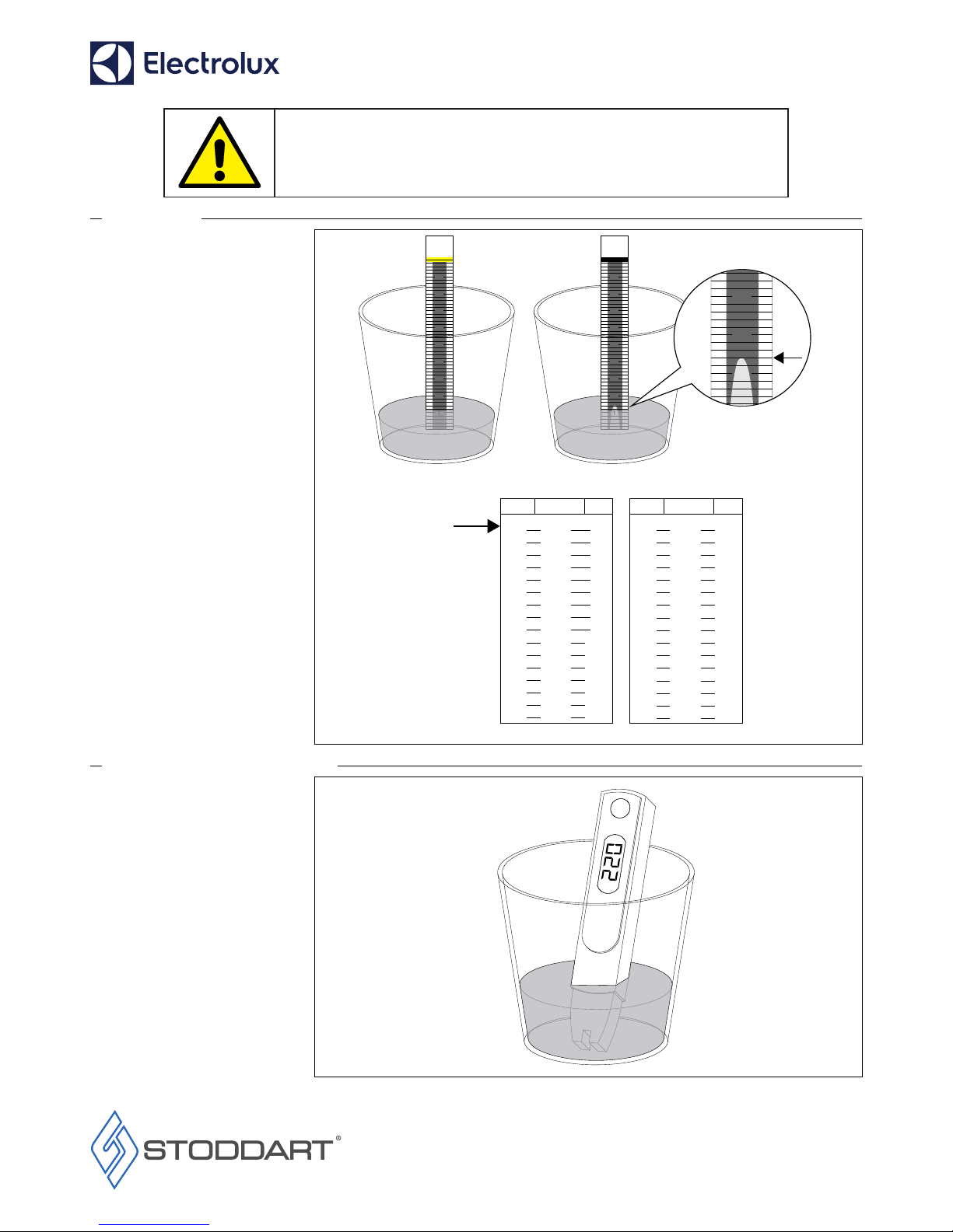
Chloride Test
1. Remove Titrator from bottle and
replace bottle cap immediately.
2. Insert lower end of the Titrator into
water to be tested (approx 20mm of
water). DO NOT allow water to touch
yellow completion band at top of
Titrator.
3. Allow water to completely saturate the
wick of Titrator. Reaction is complete
when yellow band turns dark.
4. Note where the white chloride peak
falls on the scale. This represents the
unit value.
5. Refer to the table to convert the
Titrator units into salt concentration.
* Readings higher than 1.4 (32PPM)
require a Reverse Osmosis Unit to be
installed.
Total Dissolved Solids (TDS) Test
1. Remove the cover from the TDS meter,
turn on by pressing the On/Off button.
The display should read 000.
2. Insert lower end of the TDS meter into
water to be tested (approx 20mm of
water). DO NOT completely submerge.
3. Wait 5-10 seconds.
4. The number displayed on meter is
the TDS (Total Dissolved Solids) of the
water expressed in PPM (parts per
million) e.g. TDS = 220PPM.
5. When finished, turn the TDS meter off.
1
2
3
4
5
6
7
8
9
1
2
3
4
5
6
7
8
9
1
2
3
1.4
1.6
1.8
2.0
2.2
2.4
2.6
2.8
3.0
3.2
3.4
3.6
3.8
4.0
4.2
4.4
0.005
0.006
0.007
0.009
0.010
0.011
0.013
0.014
0.016
0.017
0.019
0.021
0.023
0.025
0.027
0.030
32
39
45
53
60
68
77
86
95
106
116
128
140
152
166
180
4.6
4.8
5.0
5.2
5.4
5.6
5.8
0.032
0.035
0.038
0.041
0.044
0.048
0.051
196
212
229
248
267
288
311
6.0 0.055 335
6.2 0.060 361
6.4 0.064 389
6.6 0.069 419
6.8 0.074 452
7.0 0.080 487
7.2 0.087 525
7.4 0.093 567
7.6 0.101 613
Units %NaCI CI Units %NaCI CI
ppm(mg/L)
Limit*
ppm(mg/L)
IMPORTANT!
Selection of the correct water ltration system to suit local water
conditions is CRITICAL. Failure to install the correct system according
to the following guidelines will void warranty.
Page 5

Installation
Page 4
Due to continuous product research and development,
the information contained herein is subject to change without notice.
www.stoddart.com.au
www.stoddart.co.nz
Water
Supply Test
Call
Stoddart
1300 307 289
Chloride
(Cl)
TDS
Greater Than
32PPM (Parts Per Million)
BWT Unit
Reverse Osmosis Unit
Less Than
32PPM
Less Than
60PPM
Greater Than
60PPM
Filtration System
• After testing the quality of your water supply use the below chart to determine you water filter requirements.
Page 6

Installation
Page 5
Due to continuous product research and development,
the information contained herein is subject to change without notice.
www.stoddart.com.au
www.stoddart.co.nz
300mm
500mm
Minimum
clearance from
non-heat source
Minimum
clearance from
heat source
Positioning
• The oven must be installed under an
extraction canopy that meets
AS 1668.2.
• To allow access to service panel and
protection of the control components,
the left hand side of the Combi oven
must have the following minimum
clearances:
Heat Source:
- 500mm clearance from another heat
source, in order to protect the oven
control components and allow access
to the service panel.
Non-Heat Source:
300mm clearance from a non-heat
source to allow access to the service
panel.
• Failure to adhere to these clearances
will potentially void the oven warranty
or add service costs due to lack of
access.
• Using a spirit level, ensure that the
Combi oven is level. Adjust the foot
height to level Combi oven.
• If using a stand, level the stand by
adjusting the feet, then level the Combi
oven.
Page 7

Installation
Page 6
Due to continuous product research and development,
the information contained herein is subject to change without notice.
www.stoddart.com.au
www.stoddart.co.nz
Drainage Connection
• Drain kit is supplied with oven as
illustrated. Any modification or
extension to the kit must be able to
resist temperatures up to 100°C.
• Plumb supplied waste pipes to the
Tundish.
• Tundish needs to be a minimum of
300mm left or right from the oven
waste outlet.
• Tundish should never be located
directly below the waste outlet, or
close to or under the oven control
compartment. Steam from drainage
should not be allowed to rise
up underneath the oven control
compartment.
• Waste pipe must sit 25mm above the
Tundish.
• Secure waste pipe to the Combi oven.
Securing bracket is attached to top
of the Combi oven. Remove screw,
reposition bracket, then secure in
place with previously removed screw.
25mm
300mm
300mm
Oven Waste Outlet
25mm
300mm
300mm
Oven Waste Outlet
Page 8

Installation
Page 7
Due to continuous product research and development,
the information contained herein is subject to change without notice.
www.stoddart.com.au
www.stoddart.co.nz
Oven Cleaner Connection (20 Grid)
• Connect the oven cleaner and rinse aid
hoses to oven.
- Rinse aid (blue) on left side.
- Oven cleaner (red) on right side.
• Attach correct hoses directly to oven
cleaner and rinse aid bottles.
Detergent Tray (6 Grid, 10 Grid)
• Connect locking pin to underside of
oven.
• Insert bracket into holes located on
underside of oven.
• Slide detergent tray between bracket
and oven. Secure by rotating the
locking pin clockwise 90°.
• Detergent tray is split into two
compartments:
- Rinse aid (blue) on left side.
- Oven cleaner (red) on right side.
Optional Storage Rack
Oven Cleaner
(Red)
Rinse Aid
(Blue)
90°
Page 9

Installation
Page 8
Due to continuous product research and development,
the information contained herein is subject to change without notice.
www.stoddart.com.au
www.stoddart.co.nz
CWI-1
Filtered Water
CWI-2
Non Filtered Water
Water Supply
With
Isolation Valve
Water Flow
Direction
Filtration
System
150-350 kPa
(22-65 psi)
150-350 kPa
(22-65 psi)
No Filtration
System
Minimum Flow Rate
Refer to specific
installation guide
supplied with the
water filter
10LPM flow rate
6,10,10x2 tray oven
20LPM flow rate
20,40 tray oven
F
E
D
Supplied
Connectors
RO Filter
BWT Filter
B
C
A
Water Connection
• Water connections are labelled on the
service panel.
• Isolation valve must be installed at the
water supply outlet.
• CWI-1: The Combi oven requires
filtered water supplied to its steam
generation system.
Water pressure must be150-350 kPa
(22-65 psi) at oven connection.
• CWI-2:The Combi oven requires
unfiltered water supplied to its wash
system.
Water pressure must be150-350 kPa
(22-65 psi) at oven connection.
Minimum flow rate:
10LPM - 6,10,10x2 tray oven.
20LPM - 20,40 tray oven.
BWT Filter Supplied Connectors:
• A: Manifold fitting with 1 cap x1
• B: Non-Return Valve x1
• E: 3/4 BSB Hex Nipple x1
RO Filter Supplied Connectors:
• D: Manifold fitting with 2 caps x1
• E: Non-Return Valve x1
• F: 3/4 BSB Hex Nipple x1
Page 10

Installation
Page 9
Due to continuous product research and development,
the information contained herein is subject to change without notice.
www.stoddart.com.au
www.stoddart.co.nz
Electric Oven - Power
• Oven is to be wired to the electrical
supply by a licensed technician in
accordance with AS/NZS60335.1.
• Supply must have an isolation switch.
• Remove the two screws at the base
of the service panel, remove service
panel.
• Correctly wire the oven to terminal.
• Re-install service panel.
Electric Oven
Electric Oven
Gas Oven - Power
• Gas ovens only.
• Oven is to be connected to the gas
supply by a licensed technician in
accordance with AS/NZS5601.
• Supply must have an isolation valve.
• Connect gas line to gas connection on
underside of oven.
• Stoddart is to be contacted for the gas
setting adjustment. Ph:1300307289
• No external appliance gas regulator is
required.
• The ovens electrical connection is
supplied via a 10Amp plug and lead,
for connection to an appropriately
rated GPO.
Gas
Supply
Page 11

Notes
Page 10
Due to continuous product research and development,
the information contained herein is subject to change without notice.
www.stoddart.com.au
www.stoddart.co.nz
Page 12

Page 11
www.stoddart.com.au
International
Sales
Tel: +617 3440 7600
Email: sales@stoddart.com.au
Service / Spare Parts
Tel: +617 3440 7600
Email: service@stoddart.com.au
Email: spares@stoddart.com.au
www.stoddart.co.nz
New Zealand Business Number: 6837694
New Zealand
Sales
Tel: 0800 79 1954
Email: sales@stoddart.co.nz
Service / Spare Parts
Tel: 0800 935 714
Email: service@stoddart.co.nz
Email: spares@stoddart.co.nz
www.stoddart.com.au
Australian Business Number: 16009690251
Australia
Sales
Tel: 1300 79 1954
Email: sales@stoddart.com.au
Service / Spare Parts
Tel: 1300 307 289
Email: service@stoddart.com.au
Email: spares@stoddart.com.au
 Loading...