

Page 1
Affinity Front Load Washer
Service and Diagnostics
Page 2

Teardown and Component Operation
Page 3

Dispenser Drawer
Pull out the detergent drawer and push down on the “Push” tab.
Page 4
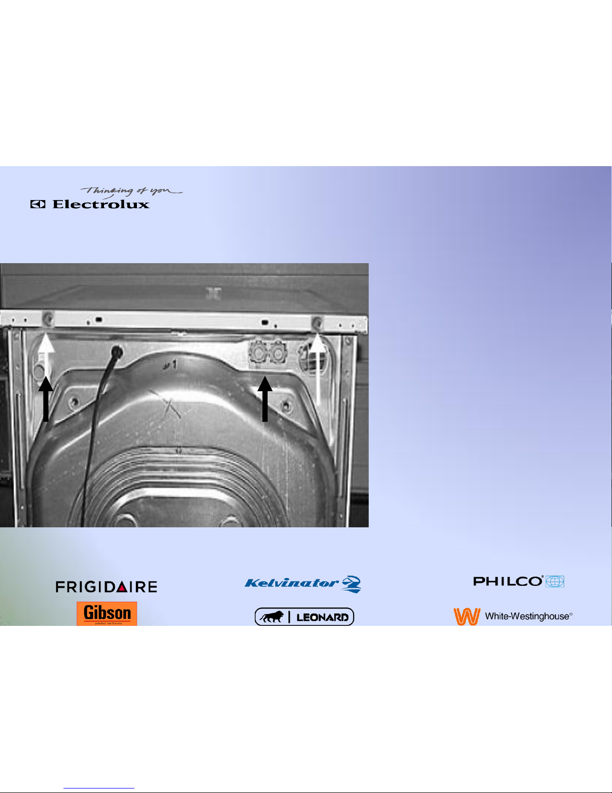
Main Top
•
Remove the two screws on
the rear of the main top.
•
Slide back
Page 5
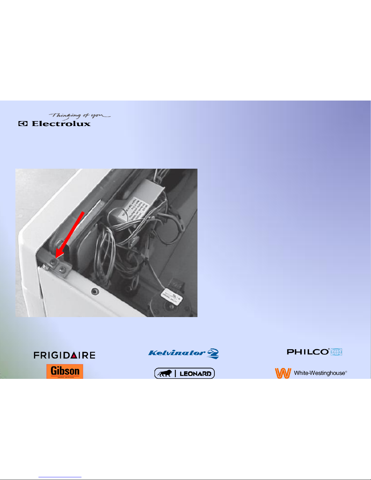
Console
Remove the two screws, one
on each end, holding the
console to the top of the side
panels
Page 6

Console
Remove the three
screws located
behind the dispenser
drawer
Page 7
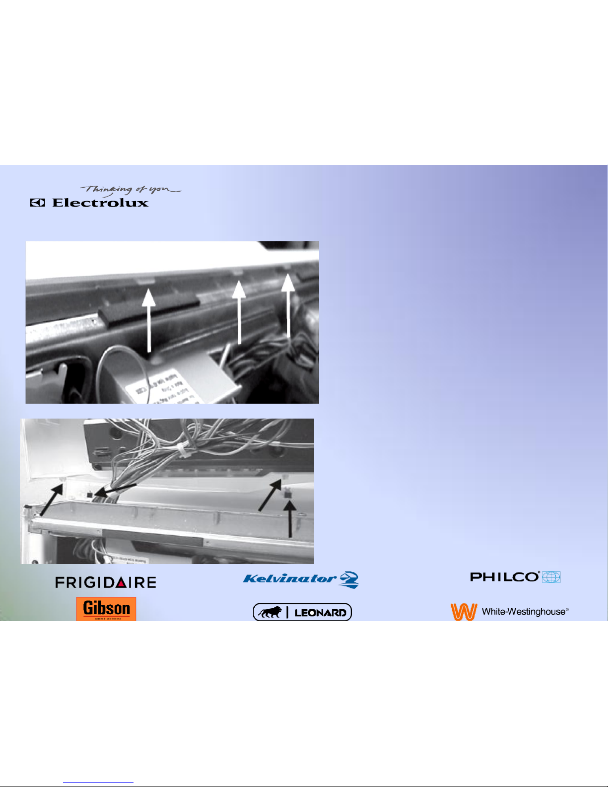
Console
Lift the three tabs on the top of
the console from the mounting
plate and roll the console
forward, while lifting up to
release the bottom tabs from
the front panel.
Top tabs
Bottom tabs
Page 8
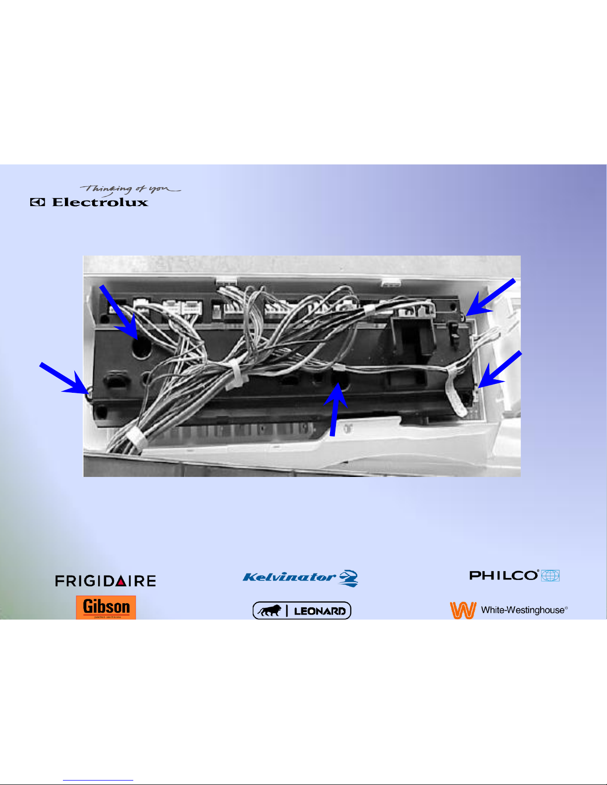
Electronic Control
Remove the five screws and disconnect wires
Page 9
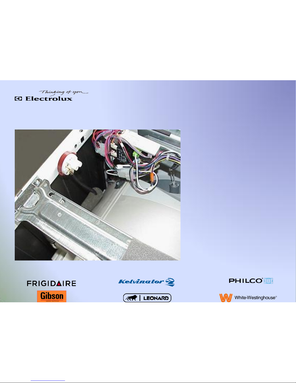
Pressure Switch
Disconnect pressure hose and
wires
Turn the pressure switch one
quarter turn and lift out
Page 10
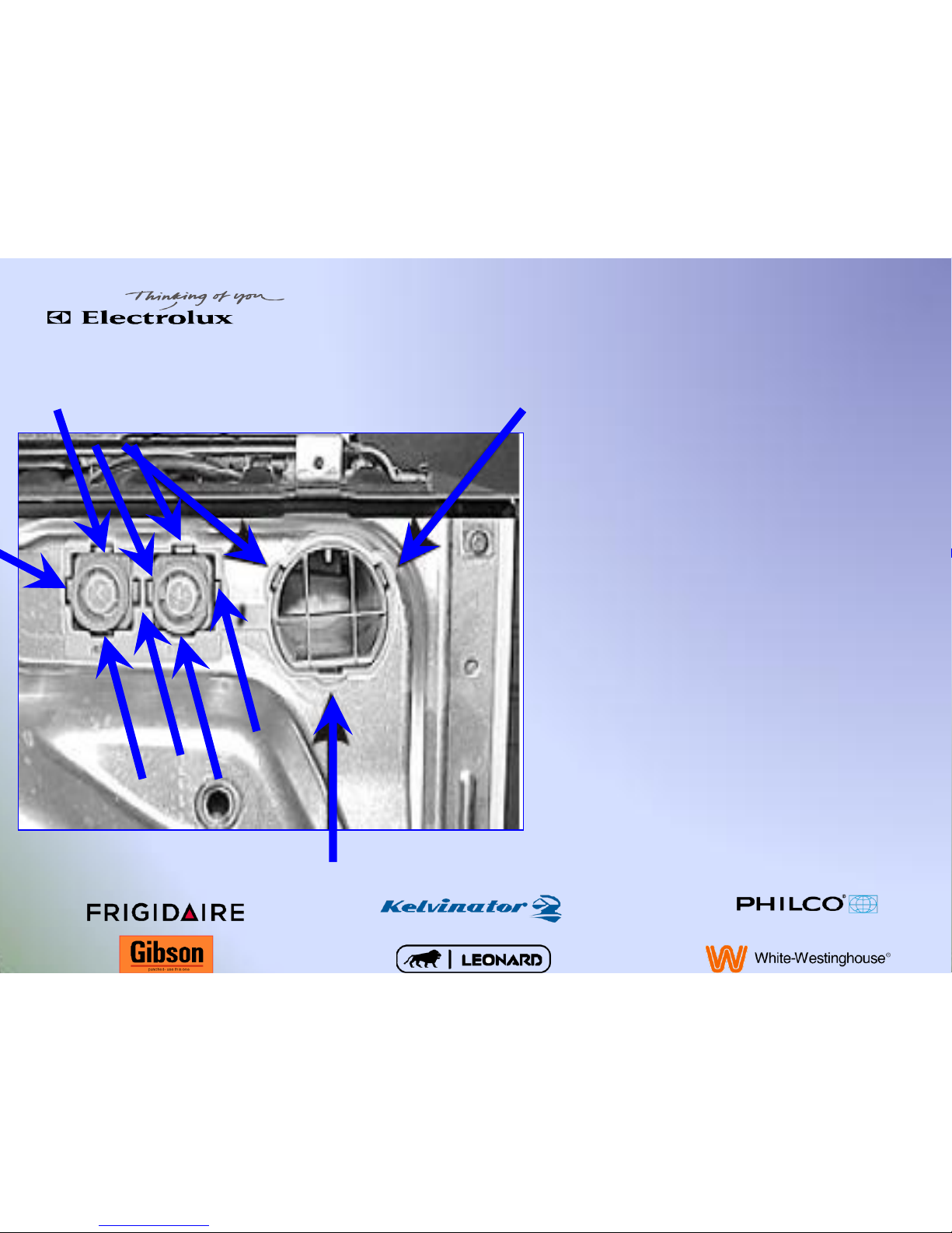
Vent Tube & Water Valve Grommet
To remove the vent tube,
water valve or dispenser first
the grommet located at the
upper right side at the back of
the washer needs to be
removed.
Release the 11 locking tabs
with a small screwdriver.
Page 11
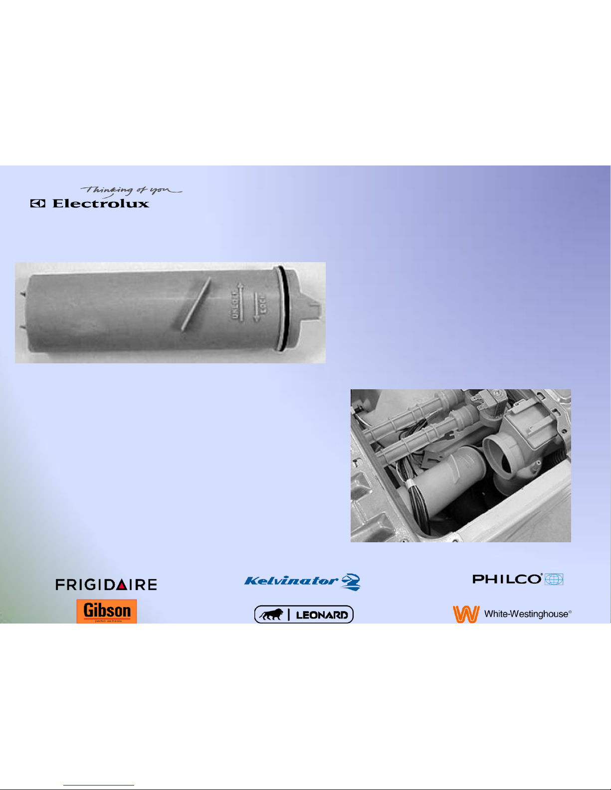
Vent Tube
Turn the vent tube counter
clockwise and pull back.
Push the tube forward and down
to release from rear hole.
Page 12
Water Valve Removal
Disconnect the electrical and
remove the two screws located
on the upper side and lower
right side of the valve.
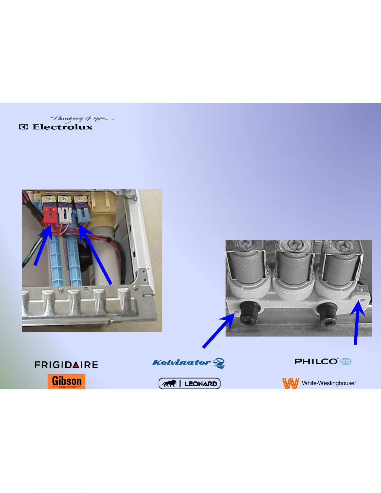
Page 13
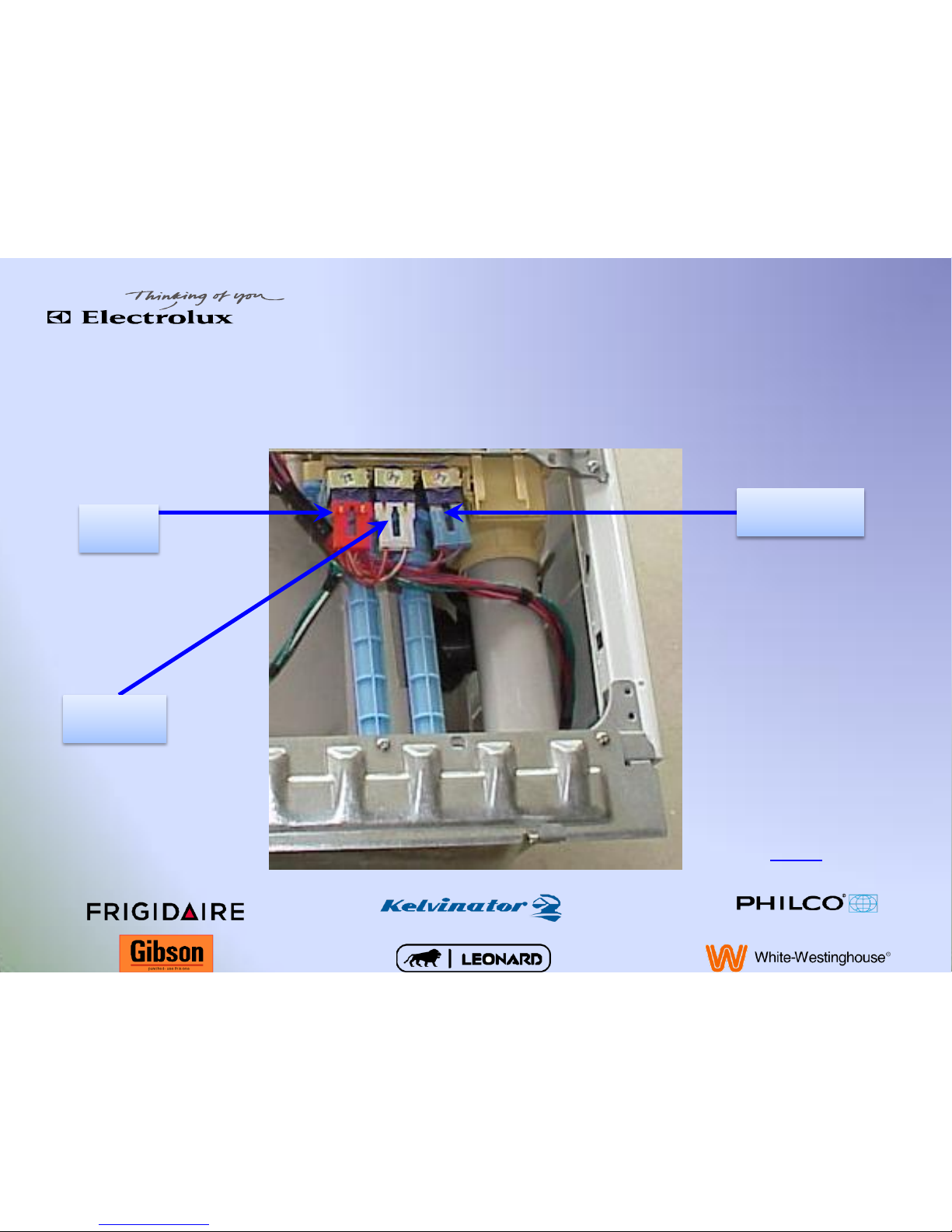
Water Valve
Bleach
Wash
Hot
Valve operation
Page 14
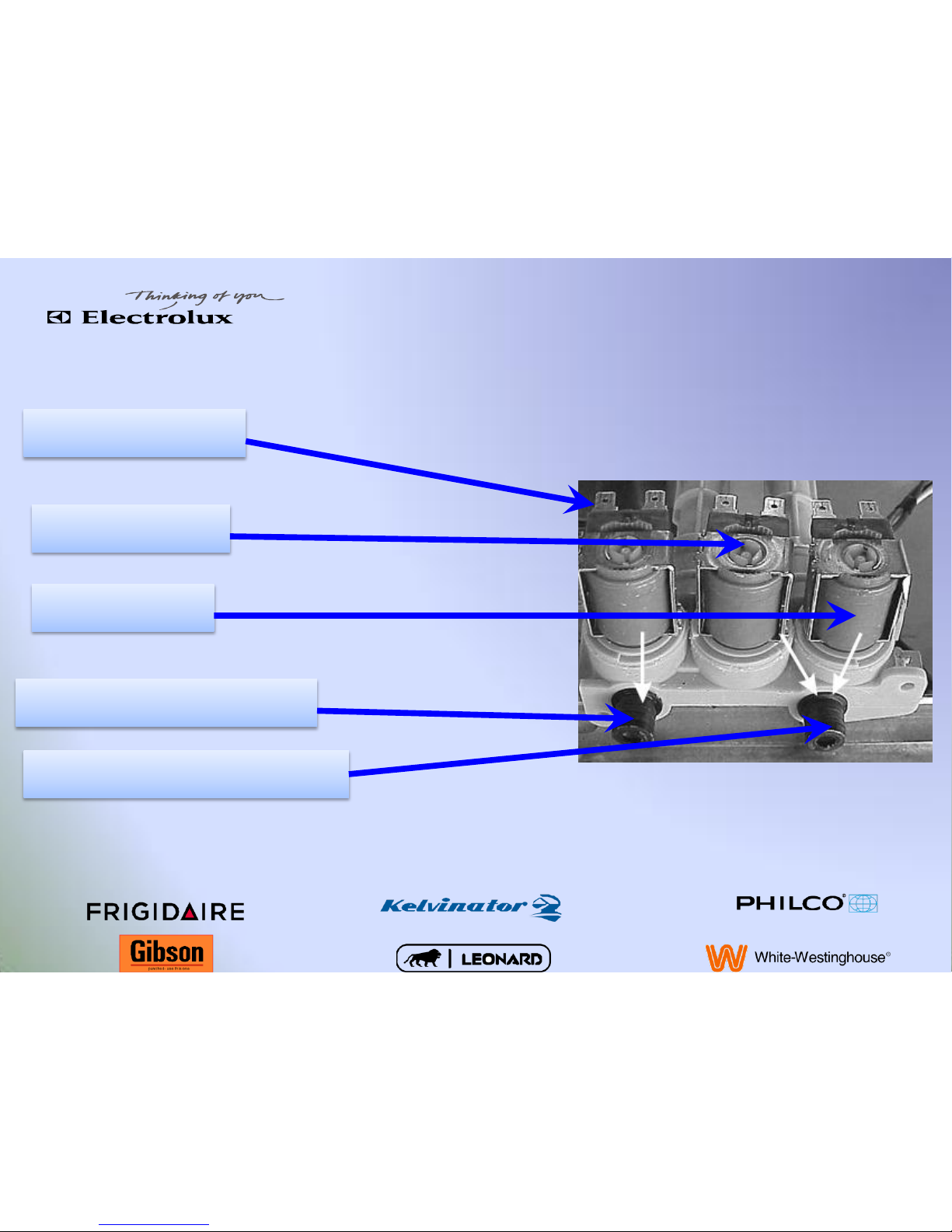
Water Valve Operation
Bleach Valve
Wash Valve
Hot Valve
Wash & Hot Port to Dispenser
Bleach Port to Dispenser
Page 15
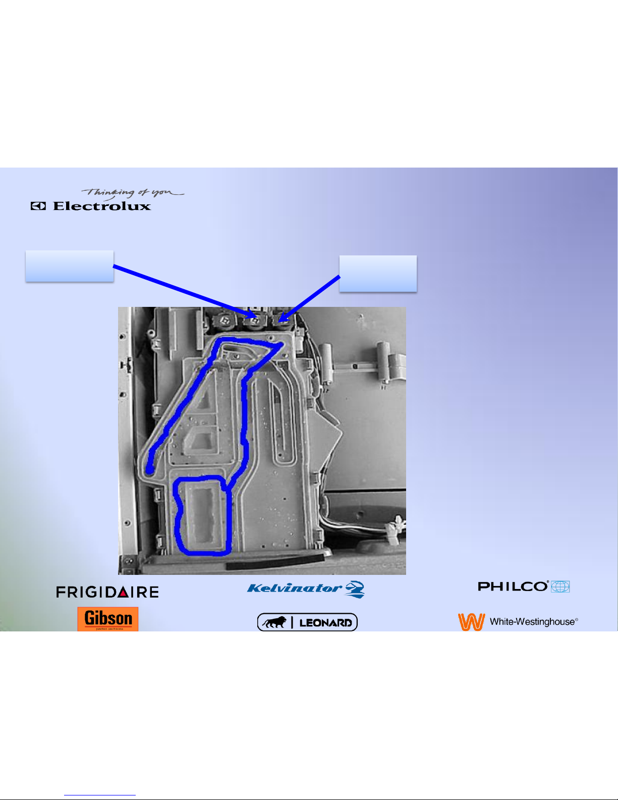
Dispenser
During fill the wash valve
(cold) and the hot valve
are engaged depending
on what temperature
you select fill the main
dispenser and the ART
(Advanced Rinse
Technology)
Main Fill
Wash Valve
Hot Valve
Page 16

Dispenser
During the bleach fill only the bleach
valve is energized filling the bleach
compartment.
Bleach Fill
Bleach Valve
Page 17

Dispenser
During the fabric softener fill the
Bleach and Hot valve are energized
when the warm rinse is selected. The
Bleach and the Wash valves are
energized. As the water runs out
both ports the water streams meet
and colloid making a steady stream
into the fabric softener section.
Fabric Softener Fill
Wash
Valve
Bleach
Valve
Hot Valve
Page 18

Dispenser Removal
Disconnect the outlet hose Disconnect the ART Hose
Page 19

Dispenser Removal
Remove two screws at the rear
of the dispenser
Remove two screws at the
front of the dispenser behind
the drawer
Page 20

Dispenser Removal
Release the (2) tabs, one on
each side, locking the housing
to the console mounting panel
Slide the housing back until
the tabs of the center cross
bar releases and the dispenser
drops down.
Page 21

Rear Panel
Remove the 6 screws removing the
bottom one last
Access
•
Belt
•Motor
•
Motor control board
Page 22

Loosen the 10 mm nut counter clockwise which
will release metal plate and decompress rubber
gasket
Heater & Thermistor
10 mm nut
Rubber Gasket Metal Plate
Page 23

When putting heater back in place make
sure it is placed into the metal clip then
tighten down the 10 mm nut.
Heater Replacement
10 mm nut
Metal Clip
Page 24

Belt & Pulley
Belt removal:
•
Just roll belt off pulley
*Note* Look at the position of the belt on the
motor shaft for proper placement
Pulley removal
•
Use a 6 mm allen turning the bolt counter
clockwise.
•
Work the pulley back and forth to remove off
spinner support shaft.
Page 25

Motor
Remove rear panel
Disconnect wire & ground plug to the
motor
Remove four 5/16 screws located at the
front and rear of the motor. Slide motor
towards the front of the washer
Page 26

Motor Control Board
To remove controller lift up
the top and disconnect
electrical connectors
Page 27

Motor Control Board
Remove the Phillips screw located towards
the rear of the unit that secures the
controller
Page 28

Motor Control Board
Lift the side of the housing up,
slide
the assembly to the rear to
disengage
the front tab and lift the
assembly
away from the washer base
*Note*
If the upper shock pin is
removed on the motor
controller side of the outer tube
it can make removal of the
controller easier
Page 29

Light Switch
Remove electrical connections and press
side tabs and push forward
Page 30

Door Bellows Spring
Remove the spring holding the door bellows
in place
Page 31

Door Switch
1st Remove two
screws
2nd Slide switch to the left
and remove wires
Page 32

Front Panel
Remove the eight screws that
hold the panel in place
Four screws on the bottom
Four screws on the top
Page 33

Front Panel
Lift up and out
to disengage
the four nylon
pins, two on
each side.
Page 34

Boot Removal
Disconnect the ART hose
Remove light (if equipped)
Place hand under bellows of
the boot and lift up
Page 35

Boot Replacement
Align the point at the top of the boot with an alignment tab on the
outer tub at the top of the lip.
Page 36

Boot Replacement
Align boot lip into the lip of the outer tub and work it on all the way
around
If needed use water or Windex for lubrication
Do not use liquid soap or fabric softener
Page 37

Boot Replacement
Fold boot into the tub
Take boot spring and place it in the
groove at the top of the boot
Page 38

Boot Replacement
At the 12:00 position hold spring in
place by wedging an object about ¾” in
diameter between boot and counter
weight or use a clamp
Page 39

Boot Replacement
Pull spring taught in the groove to the 3:00 position wedging spring in
place or using a clamp and pull spring taught to the 7:00 position wedging
the spring in place or using a clamp. Then placing the spring in the groove
all the way around.
Page 40

Counter Weight
Remove the five 7/16 bolts
holding the weight in place
.
Page 41

Pump
Disconnect hose clamps from
sump and drain hose
Remove two screws holding
the pump to the base
Page 42

Shocks
To remove shock remove the
pins.
Depress locking tab while pulling
pin to remove.
This procedure is much easier if
a deep 1/2",6 point socket (or
13 millimeter, 6 point) is used to
compress the locking tab of the
plastic pin.
Page 43

Outer Tub & Spin Basket
Loosen clamp on the
inlet hose
Loosen clamp on the air
break
Page 44

Outer Tub & Spin Basket
Remove shock pin from
outer tub and place out
of the way
Loosen sump clamp
Page 45

Outer Tub & Spin Basket
3rd Remove
the support
springs
2nd Remove
dispenser
1st Remove
water valve
and vent
tube
Page 46

Outer Tub & Spin Basket
Lift out outer tub and lay on
protected floor and remove 23, 3/8
bolts keeping front and rear tub
together
Page 47

Page 48

Page 49

Diagnostics
Page 50

Entering Diagnostics
1. Turn the Program Knob to Spin Only. This is the start
position for the diagnostic test.
2. Press Start/Pause to start the cycle.
3. Press Cancel to stop the cycle and turn off the LEDs.
4. Press any button on the console, other than the Cancel
Button, to turn on the LEDs.
5. Within 5 seconds, press and hold the Options and
Start/Pause buttons simultaneously until all the LEDs start
sequentially flashing, then release the buttons. The unit is
now in the diagnostic test mode.
Page 51

List of Tests
Listed below in order of appearance is each test that can be performed while in
the diagnostic test mode. The program knob is used to access each test.
1. User Interface Test: At this point, all of the LEDs are sequentially flashing, pressing a button
below a cluster of LEDs will light all of the LEDs in that cluster. This test is used to check the
functionality of the LEDs as well as the user interface.
2. Wash Compartment Test: Turn the program knob one position clockwise from the start
position. This will activate the hot water solenoid. At this point, hot water will flow into the
detergent compartment. This test will check the function of the hot water solenoid and the
functionality of the detergent compartment.
3. Bleach Compartment Test: Turn the program knob two positions clockwise from the start
position. This will activate the bleach water solenoid causing cold water to flow into the
bleach compartment. This test will check the function of the bleach water solenoid and
functionality of the bleach compartment.
Page 52

List of Tests
4. Softener Compartment Test: Turn the program knob three positions clockwise from the
start position. This will activate the bleach and wash water solenoids and cold water will
enter the softener compartment. This test will check the function of the wash solenoid as
well as checking the functionality of the softener compartment.
5. Door Lock Test: Turn the program knob four positions clockwise from the start position.
The door lock solenoid will open, allowing the technician to open the door. This test will
check the function of the door lock assembly, as well as the interior light.
6. Movement Test: Turn the program knob five positions clockwise from the start position.
This will fill the washer with water and start a tumbling action. Once the tumbling action
has started, the heater will turn on (if equipped). The purpose of this test is to check the
operation of the motor, motor control, water level switch, and heater (if equipped).
7. Drain and Spin Test: Turn the program knob six positions clockwise from the start position.
This test will activate the drain pump, as well as activate the door lock solenoid, allowing
the machine to start a high speed spin cycle. This test checks the drain pump, motor
control, motor, and door lock.
Page 53

List of Tests
8. Error Code Display: Turn the control knob seven positions clockwise from the start
position. This will display the last five error codes stored in the control beginning with
the most recent. This provides the technician with a history of codes that will help the
technician in their diagnosis of the failure. After the fault has been repaired, the
technician should erase the fault codes. To erase the fault codes, press the Start/Pause
and Option buttons simultaneously while in diagnostic test 8.
To exit the diagnostic test mode, there are two options that can be used to
return the unit to normal operation:
Unplug the unit from its power source, wait 5 to 8 seconds, then reapply
power to the unit or turn the program knob two or three positions clockwise
from the start position. Then press the Options and Start/Pause buttons
simultaneously for a few seconds until wash cycle LEDs appear.
Page 54

Error Codes
Error Code
Error Code Description
Test
E11
Water fill exceeded allowed time
limit
Refer to test (1).
E13
Water leakage
Refer to test (2).
E21
Water not pumping out quickly enough
Refer to test (3).
E31
Pressure switch failure
Refer to test (4).
E32
Pressure switch calibration problem
Refer to test (4).
E35
Pressure switch senses water overfill
Refer to test (5).
E38
Air trap clogged
Refer to test (5).
E41
Main control board senses the door switch is
open
Refer to test (6).
E43
Door PTC circuit failure
Refer to test (15).
Page 55

Error Codes
E44
Door closed sensing failure
Replace the main control board.
E45
Line door sensing failure
Replace the main control board.
E47
Door PTC sensing open
Refer to test (7).
E48
Door PTC sensing closed
Refer to test (7).
E49
Door sensing incongruence failure
Refer to test (7).
E4A
Door PTC sensing failure
Refer to test (6).
E52
Incorrect signal from tachometer
Refer to test (8).
E53
Low voltage to motor control board
Refer to test (17).
E54
Motor over speed failure
Refer to test (9).
E55
Motor under speed failure
Refer to test (9).
Page 56

Error Codes
E57
More than 20 amps sensed on inverter
Refer to test (9).
E58
More than 8.5 amps sensed on motor phase
Refer to test (9).
E59
No signal from tachometer for 3 seconds
Refer to test (10).
E5C
Main control received high voltage
Replace the motor control board.
E5D
Communication problem
Refer to test (11).
E5F
Main control board continuously resets
Refer to test (11).
E67
Heater relay sensing failure
Refer to test (15).
E68
Ground current leakage on heater or fuse is
open.
Refer to test (14).
E71
NTC (tub heater) failure
Check wiring. If wiring checks good, replace
main control board
E91
Communication error between main board
and user interface
Check wiring.
Page 57

Error Codes
E92
User interface and main board
communications error
Refer to test (11).
E93
Console or main board problem
Replace main control board.
E94
Main control problem
Replace main control board.
E97
Console or main board problem
Replace main control board.
E98
Communication protocol is incorrect
Replace main control board.
EA1
Power supply frequency is out of limits
Refer to Test (12).
EA2
Power supply voltage is too high
Refer to Test (12).
EA3
Power supply voltage is too low
Refer to Test (12).
EA5
Main voltage sensing failure
Refer to Test (12).
EAE
Line safety relay sensing failure
Refer to Test (12).
Page 58

Error Codes
EF1
Clogged drain pump
Unclog the drain pump.
EF2
Suds warning
Advise the customer on proper detergent
use.
EF6
Control reset
Unplug the unit for 1 minute and retry. If the
problem is not corrected, replace the main
control board.
Page 59

Customer Error Codes
“SAn”
Deep clean (Sanitary Cycle)
“cd”
Cool down (Sanitary Cycle)
“do” or “dr”
Door problem
“Err”
An error has been detected
“LOC”
Child lock has been activated
“PAU”
Cycle has been interrupted
Page 60

Tests
Test (1)
1. Is the incoming water flow normal?
2. Is the water supply turned on?
3. Is the water pressure sufficient?
4. Does water continue to fill the
washer?
5. Remove power from the unit. Did the
water fill stop?
6. Check the pressure sensor.
7. Replace the control board.
Yes. Go to step (4).
No. Go to step (2).
No. Turn on water supply.
Yes. Go to step (3)
No. Have the customer correct the pressure
problem.
Yes. Check for kinked or blocked water
supply hoses. Correct if kink or blockage is
found. If there is no kink or blockage,
replace water valve assembly.
Yes. Go to step (5).
No. Go to step (6).
Yes. Go to step (6).
No. Replace water valve assembly.
Pressure sensor checks good. Go to step (7).
Pressure sensor checks bad. Replace
pressure sensor.
Test (2)
1. Is the washer leaking water?
2. Is there an air leak in the air bell
system?
3. Check the pressure sensor.
4. Replace the main control board.
Yes. Correct water leak.
No. Go to step (2).
Yes. Correct air leak.
No. Go to step (3).
Defective. Replace pressure sensor.
Pressure sensor checks good. Go to step (4)
Page 61

Tests
Test (3)
1. Check the drain hose for restrictions.
2. Start the washer and check for 230
VAC at the drain pump.
Restriction. Correct problem.
No restriction. Go to step (2).
Zero volts. Check wiring.
Wiring checks good. Replace main control
board.
230 volts is verified at the pump. Check for
blockage in pump. If there is no blockage,
replace the pump.
Test (4)
1. Inspect the wiring between the
pressure sensor and the main control
board.
Defective wiring. Correct wiring.
Good wiring. Replace the pressure sensor. If
this does not correct the problem, replace
the main control board.
Test (5)
1. Is the water level above 120mm?
2. Does water enter the washer
continuously?
3. Remove power from the washer. Does
the water stop coming in?
4. Check the pressure switch hose.
Yes. Go to step (2).
No. Go to step (4).
Yes. Go to step (3).
No. Replace the main control board.
Yes. Check valve wiring for shorts. If wiring
checks good, replace main control board.
No. Replace water valve assembly.
Is there a restriction of air leak? If not,
replace pressure switch.
Page 62

Tests
Test (6)
1. Is the door closing?
2. Locate plug J-2 on the main board.
Measure voltage from J2-1 to ground.
Yes. Go to step (2).
If 0 volts is measured. Check the door strike.
If the door strike checks good, replace the
door switch assembly.
If 230 volts are measured, replace the main
control board.
Test (7)
1. Remove the door lock assembly and
measure the resistance of the wax
motor.
If the wax motor is shorted or open, replace
the door lock assembly.
If the wax motor measures 800 to 1500
ohms, replace the main control board.
Test (8)
1. Disconnect the plug from the drive
motor and measure the resistance
between pins 4 and 5 on the motor.
If the measurement is between 105 and 130
ohms, replace the motor control board.
If the measurement is outside of the range
of 105 -130 ohms, replace the motor.
Page 63

Tests
Test (9)
1. Remove the belt from the motor and
spin the motor pulley. Does the motor
spin freely?
2. Remove the belt from the unit and
spin the tub pulley. Does the tub spin
freely?
3. Disconnect the motor plug. Measure
resistance of motor windings by
measuring from pin 1 to pin 2, pin 1 to
pin 3, and pin 2 to pin 3. All readings
should measure between 4 to 6 ohms.
No. Replace the motor.
Yes. Go to step (3).
No. Check the tub bearings. If tub bearings
check good, check unit for obstruction
between tub and spin basket.
Yes. Go to step (3).
If readings are correct, replace the motor
control board.
If readings are incorrect, replace the motor.
Page 64

Tests
Test 10
1. Remove the belt from the motor and
spin the motor pulley. Does the motor
spin freely?
2. Spin the tub pulley. Does the tub spin
freely?
3. Disconnect the plug from the drive
motor and measure the resistance
between pins 4 and 5 on the motor.
4. Disconnect the motor plug. Measure
resistance of motor windings by
measuring from pin 1 to pin 2, pin 1 to
pin 3, and pin 2 to pin 3. All readings
should measure between 4 to 6 ohms.
No. Replace the motor.
Yes. Go to step (3).
No. No. Check the tub bearings. If tub
bearings check good, check unit for
obstruction between tub and spin basket.
Yes. Go to step (3).
Measurement should be between 105 and
130 ohms. If meter reads outside of those
limits, replace the motor.
If the reading is between 105 and 130 ohms,
go to step (4).
If the readings are correct, replace the
motor control board.
If the readings are incorrect, replace the
motor.
Page 65

Tests
Test 11
1. Check the wiring between the main
control board and the motor control
board.
Wiring is defective. Repair or replace wiring.
Wiring checks good. Replace the main
control first. If this does not repair the error,
replace the motor control board.
Test 12
1. Contact the power supply company to
check incoming power frequency.
If the frequency is correct, replace main
control board.
Test 13
1. Check the heating element resistance.
Element resistance should be
approximately 30 ohms.
If reading is correct, replace the main control
board.
Test 14
1. Check the resistance of the tub NTC. Is
the NTC resistance approximately 4.8K
ohms.
No. Replace the heating element.
Yes. Check the wiring.
Page 66

Tests
Test 15
1. Check the wiring between the main
control board and the user interface
board.
If the wiring is defective, correct the wiring.
If the wiring checks good, and none of the
LED’s light, replace the use interface board.
If this does not correct the error, replace the
main control board.
Note: If only one of the LED’s will not light,
replace the user interface board.
Test 16
1. Does the unit shut down shortly after
coming on?
2. Does the water valve come on and then
shut off after a short period of time?
Then does the pump come on and shut
off, and then power to the unit shuts
off?
3. If nothing happens when the start
button is pushed, replace the main
control board.
Yes. Check wiring to the door lock switch. If
the wiring checks good, replace the door lock
switch.
No. Go to step (2).
Yes. Replace the door lock switch.
No. Go to step (3).
Test 17
1. Check the wiring between the main
control board and the motor control
board.
If the wiring checks good, replace the motor
control board.
Page 67

Accessing Error Codes
• Wake the washer by pressing any button other
than Cancel.
• Wait 5 seconds.
• Press and hold the Start/Pause and Cancel
buttons simultaneously. The unit will beep
and the last 5 store error codes will be
displayed as long as the Start/Pause and
Cancel buttons are pressed together.
Page 68

Clear Error Codes
• Enter the diagnostic mode as described above.
• Turn the control knob seven positions
clockwise from the start position.
• Press and hold the Options and Start/Pause
buttons for 3 seconds. This will clear the error
codes.
• Exit the diagnostic mode as described above.
Page 69

Demo Mode
Demo Mode: The demo mode is used to exhibit the
functions of the machine in a showroom setting.
When the unit is operating in demo mode it
displays the following characteristics:
Cycle times are shorter than in the operating mode.
The water fill function of the unit is disabled.
The drain function of the unit is disabled.
The heater is disabled.
The spin cycle is disabled.
Page 70

Demo Mode
To enter the demo mode, execute the following procedure:
Press the Cancel button.
Wake up the user interface by pressing any button on the console
other than the Cancel button.
Move the program to position two (rinse cycle).
Press and hold the Start/Pause and Spin Speed buttons
simultaneously for five seconds. These buttons must be pressed
exactly at the same time to enter the demo mode.
After pressing the Start/Pause and Spin Speed buttons
simultaneously the unit will beep. After the unit beeps, press the
Start/Pause button. The unit is now in demo mode.
This procedure must be completed within 7 seconds from waking up
the user interface.
Page 71

Demo Mode
Now that the washer is in demo mode, any cycle
can be selected and started and the unit will turn
on the interior drum light, count down the cycle
time in the display, and perform a tumbling
action.
The demo mode will be saved even after the unit
is disconnected from power or if there is a power
interruption. To exit the demo mode, follow the
same procedure used to enter the demo mode.
 Loading...