

Electrolux 990EN Service Manual
ELECTROLUX ZANUSSI S.p.A.
Spares Operations Italy
Corso Lino Zanussi,30
I - 33080 PORCIA /PN (ITALY)
Fax +39 0434 394096
Edition: 10.2003
Publication
number
599 36 09-90
SERVICE MANUAL
DISHWASHERS
DISHWASHER
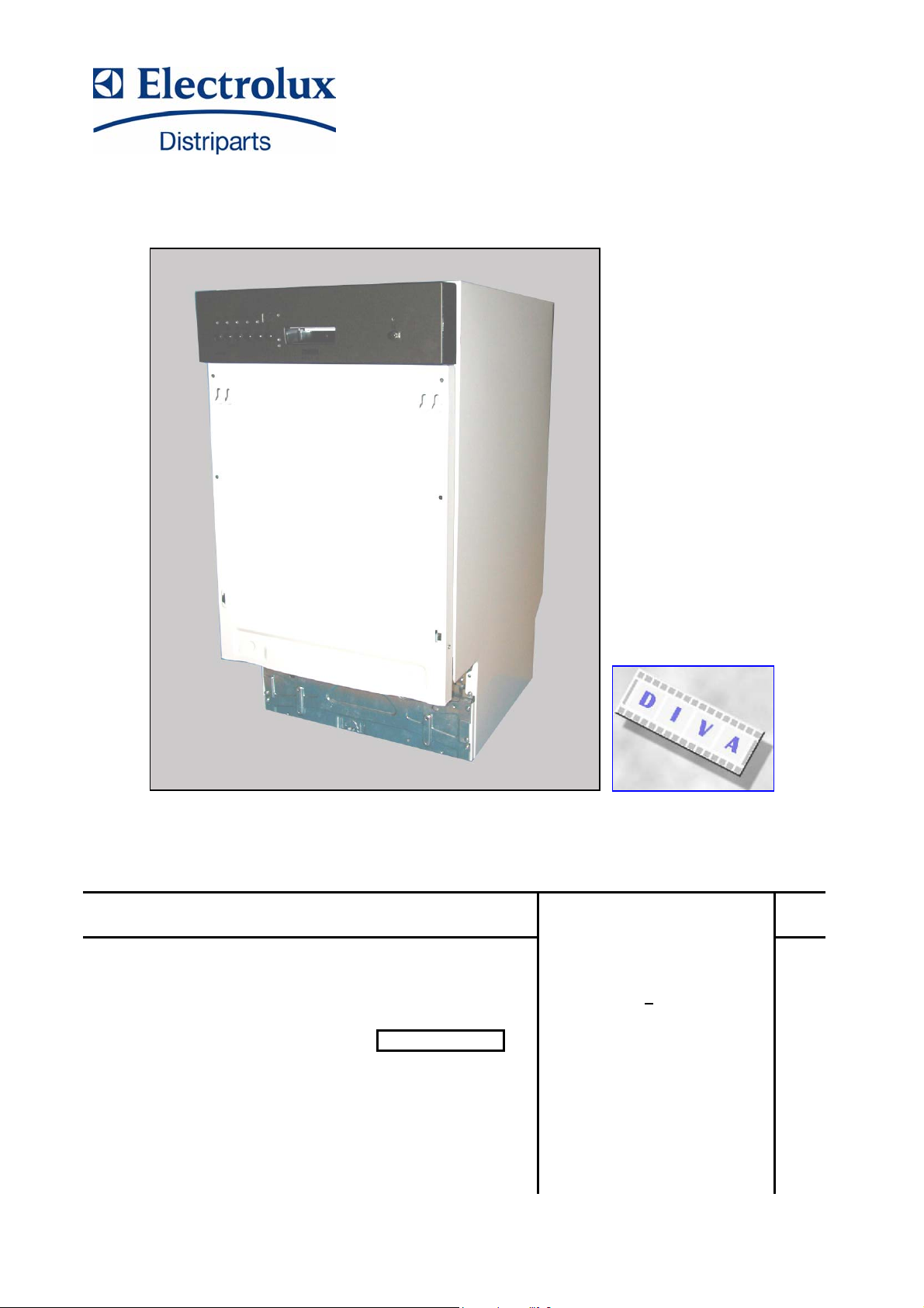
“DIVA” 45cm
Free-Standing (F. S.)
Partially integrated (B. I.)
Fully integrated (F. I.)
Basic characteristics
Production ZM
Solaro (MI) - ITALY
911 6xx xxx
SOI/TD - PR 1/34 599 36 09-90

SOI/TD - PR 2/34 599 36 09-90

TABLE OF CONTENTS
INTRODUCTION ................................................................................................................................................. 4
1
1.1 PURPOSE OF THIS SERVICE MANUAL....................................................................................................... 4
1.2 PRESENTATION........................................................................................................................................... 5
1.3 GENERAL CHARACTERISTICS....................................................................................................................6
1.4 FIELD OF APPLICATION .............................................................................................................................. 6
1.5 ELECTRONIC MODULE................................................................................................................................6
1.6 DEFINITION OF STYLINGS AND FUNCTIONS ............................................................................................. 7
1.7 STRUCTURAL CHARACTERISTICS ............................................................................................................. 9
2 STRUCTURAL CHARACTERISTICS ................................................................................................................. 10
2.1 BASE .......................................................................................................................................................... 10
2.2 DOOR......................................................................................................................................................... 10
2.3 TUB ............................................................................................................................................................ 12
2.4 HYDRAULIC SYSTEM................................................................................................................................. 13
3 HYDRAULIC AND FUNCTIONAL CHARACTERISTICS ..................................................................................... 14
3.1 WATER FILL TANK..................................................................................................................................... 15
3.2 WATER SOFTENING SYSTEM ................................................................................................................... 15
3.3 SUMP ASSEMBLY ...................................................................................................................................... 16
3.4 DRYING DUCT............................................................................................................................................ 16
4 ELECTRICAL COMPONENTS...........................................................................................................................17
4.1 TERMINAL BLOCK ..................................................................................................................................... 17
4.2 PUSHBUTTON............................................................................................................................................ 17
4.3 TIMER......................................................................................................................................................... 17
4.4 LATCH ASSEMBLY..................................................................................................................................... 17
4.5 WASHING PUMP........................................................................................................................................ 18
4.6 CAPACITOR ...............................................................................................................................................18
4.7 DRAIN PUMP.............................................................................................................................................. 18
4.8 FILL SOLENOID VALVE.............................................................................................................................. 18
4.9 TUBE-ENCASED HEATING ELEMENT .......................................................................................................19
4.10 TEMPERATURE THERMOSTAT ................................................................................................................ 19
4.11 TEMPERATURE SENSOR.......................................................................................................................... 19
4.12 TEMPERATURE SENSOR + TURBIDITY SENSOR..................................................................................... 19
4.13 INTEGRATED DISPENSER......................................................................................................................... 20
4.14 LEVEL & ANTI-OVERFLOW PRESSURE SWITCH...................................................................................... 20
4.15 ANTI-FLOODING DEVICE...........................................................................................................................20
5 WASHING SYSTEM..........................................................................................................................................21
5.1 DEFINITION OF THE WASHING CYCLE..................................................................................................... 21
6 HYDRAULIC CIRCUIT....................................................................................................................................... 22
6.1 PATH OF WATER INTAKE - "SHORT TANK" .............................................................................................. 22
6.2 PATH OF WATER INTAKE - "LONG TANK"................................................................................................. 23
6.3 WATER FILL SYSTEM - FUNCTIONAL DESCRIPTION ............................................................................... 24
6.4 ANTI-OVERFLOW SAFETY LEVEL............................................................................................................. 24
6.5 WATER SOFTENING SYSTEM ................................................................................................................... 25
6.6 DEFINITION OF THE REGENERATION SYSTEM ....................................................................................... 27
7 DEFINITION OF THE DRYING CIRCUIT ...........................................................................................................28
7.1 "NORMAL - DRY" DRYING.......................................................................................................................... 28
7.2 "ACTIVE - DRY" DRYING............................................................................................................................ 29
7.3 "TURBO - DRY" DRYING SYSTEM .............................................................................................................30
7.4 CHECKING THE EFFICIENCY OF THE COMPONENTS ............................................................................. 31
7.5 ELECTRICAL CIRCUIT DIAGRAM - DIVA_ ELM -........................................................................................ 32
7.6 BASIC ELECTRICAL DIAGRAM - DIVA_ ELM - ........................................................................................... 33
7.7 TIMER DIAGRAM - DIVA_........................................................................................................................... 34
SOI/TD - PR 3/34 599 36 09-90

1 INTRODUCTION
1.1 PURPOSE OF THIS SERVICE MANUAL
The purpose of this Service Manual is to provide Service Engineers, who already have the basic
knowledge necessary to repair household dishwashers, with information of a general nature regarding
the new 45 "DIVA" range of dishwashers.
The aspects described in this document relative to the structural and hydraulic characteristics and the
basic circuits are common to all the appliances in the range, both with electromechanical and electronic
control systems.
More detailed information regarding individual models may be found in the specific information
documents for each specific functionality.
This information covers:
- Technical characteristics
- Circuit diagrams
- Exploded diagrams and Lists of spare parts
may be found in the Service Notes and Service Manuals issued separately for each specific model.
SOI/TD - PR 4/34 599 36 09-90

1.2 PRESENTATION
NEW TECHNOLOGY: DISHWASHERS CREATED WITH COMPUTER-AIDED DESIGN SYSTEMS
AND BUILT USING MODERN INDUSTRIAL TECHNOLOGY.
RESULT:
Drawing on our vast experience and resources, combined with the latest technical and structural
techniques, we have produced this range of innovative appliances to meet the demands of a market
that is constantly evolving.
1.2.1 MAIN CHARACTERISTICS
1.2.1.1 STRUCTURAL CHARACTERISTICS:
- Modular and convertible, in three versions: Free-standing, Partially built-in, Fully built-in
- Monobloc load-bearing base in sound-absorbing plastic material.
- Two removable side panels.
- Styling variable to meet the various configurations requested.
- Simplification of free-standing and built-in installation.
- On built-in models, the rear foot can be adjusted from the front of the appliance.
1.2.1.2 HYDRAULIC CHARACTERISTICS:
- Newly-designed integrated hydraulic circuit.
- New integrated sump.
- New water softening system.
- Softening of regeneration water up to 90°F - 50°D.
- Optimization of the regeneration system with 5 to 10 levels of regeneration.
- Manual regulation of the regeneration level on electromechanical models, software regulation for
electronic models.
1.2.1.3 ELECTRICAL CHARACTERISTICS:
- New washing pump motor.
- New drain pump motor.
- New types of timer.
- New types of electronic boards (PCB).
1.2.1.4 CONTROL AND SAFETY SYSTEMS:
- Measurement of water temperature by means of thermostats or temperature sensors for electronic
models.
- Measurement of water fill level by means of a pressure switch.
- Anti-overflow safety system using a pressure switch.
- Anti-leakage safety system using an anti-flooding device.
- Protection against overheating using a safety thermostat (software for electronic models).
- Electrical door aperture safety system.
- Functional protection with constant monitoring (with software control for electronic models).
1.2.1.5 SOUND-PROOFING:
- Improved silence thanks to the use of new materials and new construction technologies.
1.2.1.6 SERVICE:
- Easier access to components thanks to careful positioning, from the two removable side panels and
from the frontal plinth.
Electronic models:
- Facilitation of repairs using diagnostics tests and trouble-shooting procedures.
- The washing parameters can be modified to improve washing performance.
SOI/TD - PR 5/34 599 36 09-90

1.3 GENERAL CHARACTERISTICS
Power supply ⇒ 230 V / 50 Hz (limits 187−254 V)
Total power absorption ⇒ 2300 W (with 2100 W heating element)
Water supply ⇒ Min. / Max. Pressures: 5 − 80 N/cm
2
Load capacity ⇒ 8/9 place settings
Noise level ⇒ db 50 / 56 (A) sound pressure (electromechanical)
⇒ db 46 / 50 (A) sound pressure (electronic)
Class ⇒ [AAA] - [AAB] (electronic models)
* Declared consumption [BIO AAB programmes]
- Water - Energy - Duration of cycle ⇒ 14Lt. - 1,10 KWh - 150 Min
* Example of programme declared to the various consumer institutes (electronic models).
1.4 FIELD OF APPLICATION
Washing system ⇒ CONTINUOUS (electromechanical)
⇒ CONTINUOUS /IMPULSE OPERATION (electronic)
Control system ⇒ TIMER (electromechanical)
⇒ CONTROL BOARD (electronic)
Water fill level ⇒ PRESSURE SWITCH CONTROL (electromechanical)
⇒ PRESSURE SWITCH+SOFTWARE CONTROL (electronic)
Water heating ⇒ HEATING ELEMENT IN PROTECTIVE TUBE
Temperature control ⇒ THERMOSTATS (electromechanical)
⇒ NTC TEMPERATURE SENSOR (electronic)
Drying system ⇒ NORMAL DRY (electromechanical)
⇒ ACTIVE DRY (electronic)
⇒ TURBO DRY (electronic)
Safety systems ⇒ HYDRAULIC/ELECTRICAL SYSTEMS (electromechanical)
⇒ TOTAL PROTECTION: HYDRAULIC/ELECTRICAL +
SOFTWARE (electronic)
Alarms ⇒ SOFTWARE SYSTEM WITH VISUAL DISPLAY (electronic)
1.5 ELECTRONIC MODULE
Power board ⇒ MAIN OPERATIONAL CONTROL (built-in microprocessor)
Comandi / Visualizzazione ⇒ USER-MACHINE INTERFACE
SOI/TD - PR 6/34 599 36 09-90
1.6 DEFINITION OF STYLINGS AND FUNCTIONS
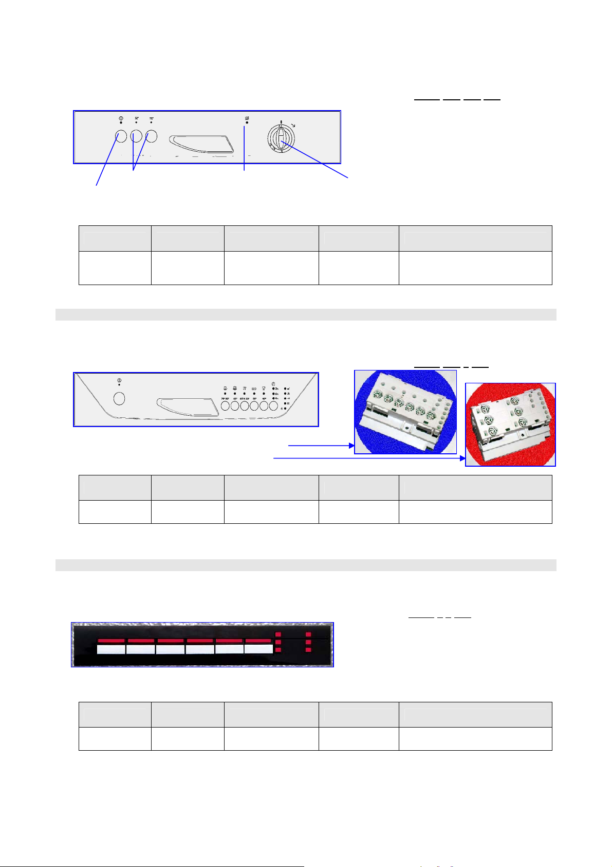
1.6.1 Control panel: - DIVA_ ELM [electromechanical] PNC 911 6
Ö Option keys Ö Salt level indicator Ö Programme selector knob
Ö ON/OFF key
1.6.1.1 DEFINITION OF FUNCTIONS
Structure Function Type of control Programmes Options
1>3 1>4 xxx
Free- Standing
/ Built- in
Electro-
mechanical
ON/OFF key
1
> 3 keys
+ knob
> 6
3
programmes
[Temp. selection 70ºC, 60ºC,
50ºC] - [Intensive] - [Bio/Eco] -
1.6.2 Control panel: - DIVA_ EDW1100 PNC 911 6
Control panel versions Ö HORIZONTAL
Ö VERTICAL
Structure
Free- Standing
/ Built- in
Electronic
Functions
EDW_1001
Type of control Programmes Options
ON/OFF key
3
> 6_keys / leds
3 > 6
programmes
[Delay /9h] - [ ½C] - [Tablet (3/1)]
1.6.3 Control panel: - DIVA_ EDW1003 PNC 911 6
Control panel versions Ö UPPER / HORIZONTAL
Structure
Fully built-in EDW_1003
Electronic
Functions
Type of control Programmes Options
ON/OFF key
3
> 6 keys / LEDs
3
> 6
programmes
[Delay /9h] - [ ½C] - [Tablet (3/1)]
[½C] -
1>2 5 xxx
3 5 xxx
SOI/TD - PR 7/34 599 36 09-90
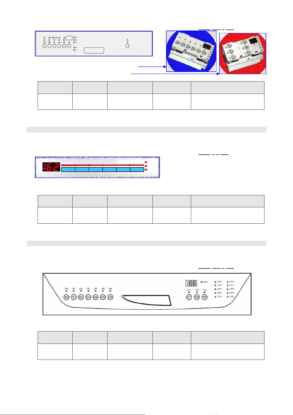
1.6.4 Control panel: - DIVA_ EDW1500 PNC 911 6 1>2 6 xxx
Control panel versions Ö HORIZONTAL
Ö VERTICAL
Structure
Free- Standing
/ Built- in
Electronic
Functions
EDW_1500
Type of control Programmes Options
ON/OFF key
3 >
6 keys / LEDs
+ display
> 6
3
programmes
[Delay /19h] - [ ½C] - [Tablet (3/1)]
1.6.5 Control panel: - DIVA_ EDW1503 PNC 911 6
3 6 xxx
Control panel versions Ö UPPER / HORIZONTAL
Structure
Fully built-in EDW_1503
Electronic
Functions
Type of control Programmes Options
ON/OFF key
3 >
6_ keys / LEDs
+ display
> 6_
3
programmes
[Delay /19h] - [ ½C] - [Tablet (3/1)]
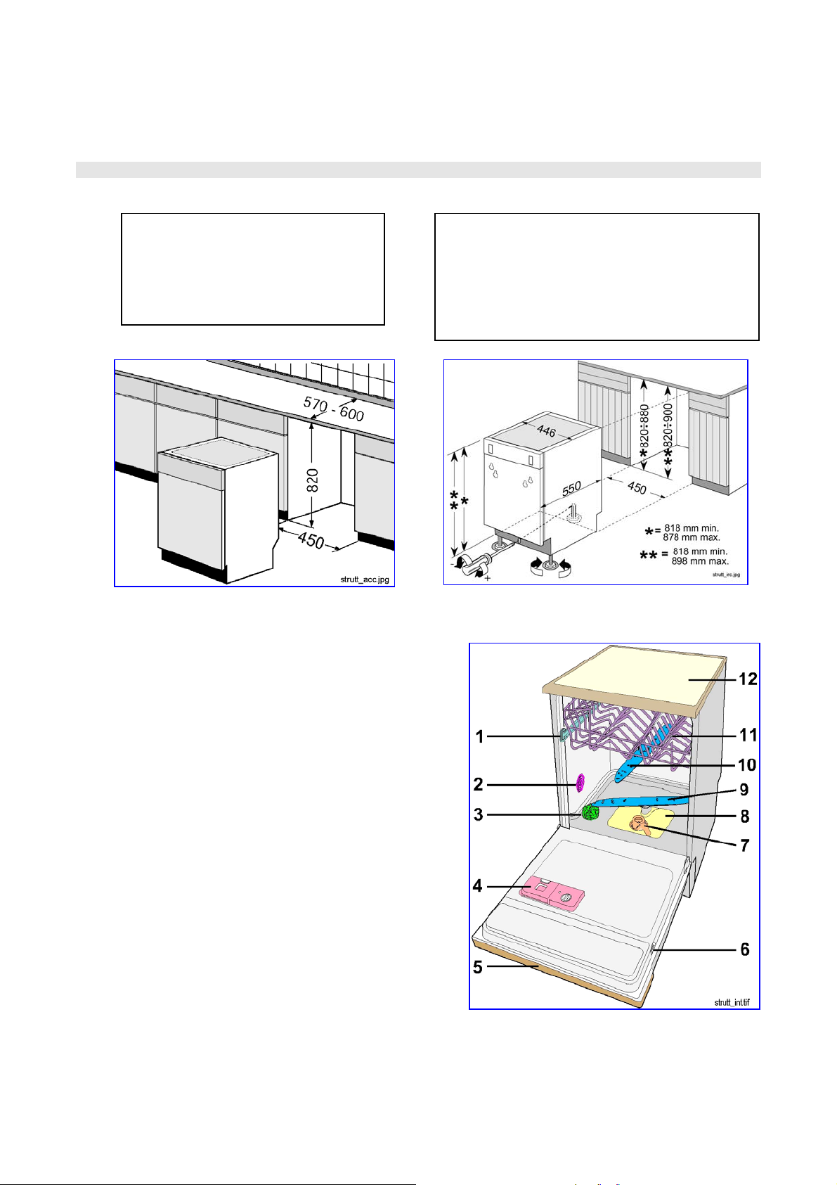
1.6.6 Control panel: - DIVA_ EDW2000 PNC 911 6
1>2 7 xxx
Control panel versions Ö FRONTAL / HORIZONTAL
Structure
Free- Standing
/ Built- in
Electronic
Functions
EDW_2000
Type of control Programmes Options
ON/OFF key
11 keys /
+ display
LEDs
6 [Delay /19h] - [ ½C] - [Tablet (3/1)]
SOI/TD - PR 8/34 599 36 09-90
1.7 STRUCTURAL CHARACTERISTICS
This convertible modular dishwasher is designed for maximum flexibility, and can be installed in the
FREE-STANDING or BUILT-IN versions.
FREE-STANDING BUILT-IN
Ø Ø
1.7.1 INTERNAL CHARACTERISTICS
1. Upper basket guide
2. Water softening level selector
3. Salt container cap
4. Detergent/rinse-aid dispenser
5. Control panel
6. Serial number plate
7. Central filter (drain)
8. Main filter (washing)
9. Lower spray arm
10. Upper spray arm
11. Upper basket
12. Work-top (free-standing versions only)
By removing the work top, the
dishwasher can be inserted beneath a
sink or a pre-existing work-top in
marble or wood, on condition that the
dimensions of the compartment are as
shown in the figure.
6
7
8
5
4
3
SOI/TD - PR 9/34 599 36 09-90
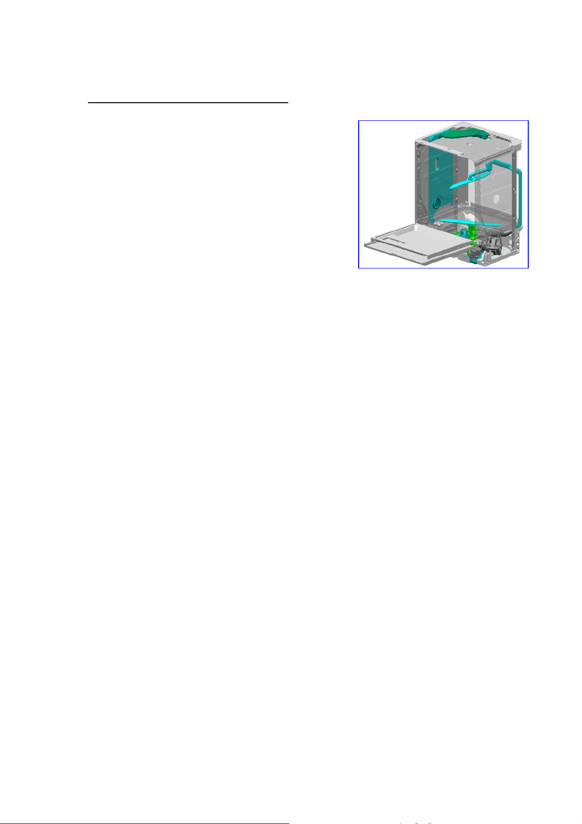
2 STRUCTURAL CHARACTERISTICS
The appliance consists of four main assemblies:
2.1 BASE
2.2 DOOR
2.2.1 CONTROL PANEL
2.2.2 INNER DOOR
2.2.3 DOOR
- BASE - DOOR - TUB - HYDRAULIC SYSTEM
These four assemblies are enclosed in a cabinet designed with the following removable parts:
- Front panel (secured by two screws)
- Two side panels (secured by six screws)
- A work-top (free-standing versions only) secured to the
structure by two screws at the rear.
The specially-shaped base is moulded in sound-absorbing plastic material.
- The base, which supports the body of the appliance, is fixed structurally to the tub.
The following components are located in the base
- The fill valve
- The integrated terminal block, power cable and anti-interference capacitor
- The washing pump capacitor
- The anti-flooding device
- The support system (rubber support blocks) for the washing pump
- The counterweight (free-standing versions only)
The door consists of the following sub-assemblies:
The control panel is in moulded plastic, and is secured to the inner door by six self-tapping screws.
The control panel may be customized for the various stylings, with different colours and silk-screened
markings, or by the application of a transparent or stainless steel panel mask.
The following components are screwed or pressure-fitted to the inside of the control panel:
- The timer or electronic board
- The door aperture handle
- The pushbutton array
- The pilot lamp diffusers.
The inner door is in non-magnetic 304 stainless steel, and is secured by two lateral hinges (using four
screws), which are secured to the two front uprights of the tub.
The following components are fitted to the interior of the inner door:
- The door latch with a built-in door aperture microswitch
- The integrated dispenser (detergent and rinse-aid)
- In the lower section, a seal with the bottom of the tub.
The door is in enamelled sheet steel, and is secured to the inner door by six screws around the
perimeter and two lateral screws.
On certain stylings (free-standing) a perimetral surround is fitted for application of a front décor panel.
The doors of built-in appliances have holes, slots and shaped sections for application of an outer door
in wood.
SOI/TD - PR 10/34 599 36 09-90
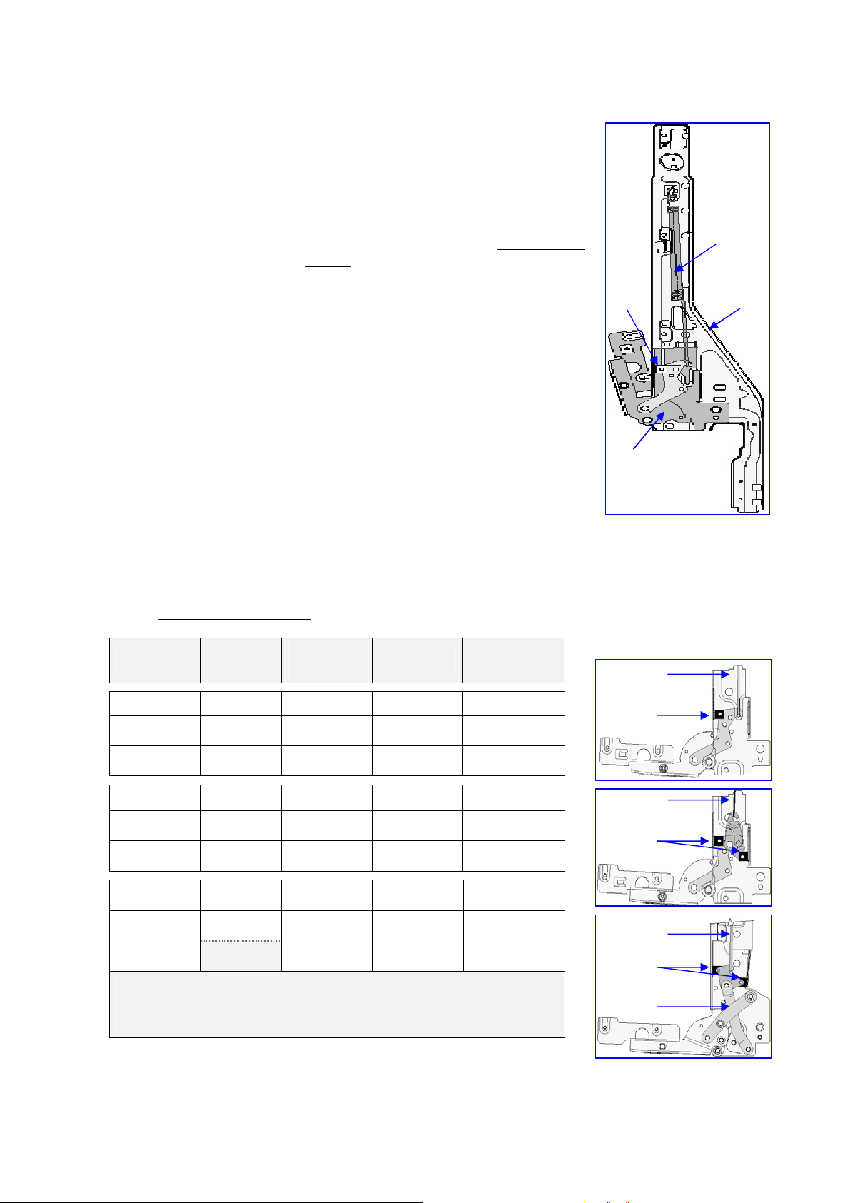
A
2.2.4 DOOR HINGE
In galvanized pressed steel, with a series of mechanisms (springs, levers, spindles) which form the
system of movement for aperture/closure of the door.
- Secured externally to the two lateral uprights (D) by pressure-fitted
couplings and screws with metric thread.
- Hinges with different functional characteristics and settings are used,
depending on the styling of the appliance.
2.2.4.1 CHARACTERISTICS & FUNCTIONS
Aperture and closure of the door is by means of a pair of self-adjusting
hinges (A) and a tensioning spring (B). The movement is self-balancing
and features an automatic "braking
" system.
The self-balancing system consists of a helical spring which is
calibrated to a fixed setting.
- The calibration depends on the overall weight of the door fitted to the
appliance.
- The helical spring is secured to the upper extremity of the upright
and to the hinge mechanism.
The automatic "braking
" system consists of a mechanical clutch.
- The clutch consists of a sliding element (C) fitted to the hinge
mechanism which, during aperture and closure of the door, slides
vertically along the surface of the hinge.
- Some hinges are fitted with a double clutch system (two sliding
elements) in order to provide a greater "braking" effect, so that doors
of greater weight are balanced in the same way.
2.2.4.2 OPERATION AND CALIBRATION
In order to cover the entire range according to the overall weight of the door (from 5.5 kg min. to 14.2
kg max.), a series of combinations has been created, and consists of three types of hinge and five
types of spring. According to the possible combinations of hinges and springs, the characteristics of
the hinge/spring assemblies
Dishwasher
structure
Type of
hinge (C)
are shown in the table below:
Type of
spring
(B)
Weight of
panel/door
Ä Ä Ä Ä Ä
FreeStanding
FreeStanding
Single
clutch
Single
clutch
Light
(blue mark)
Normal
(no mark)
-- 5,5 > 6,5 Kg
> 2 Kg 6 > 8,9 Kg
Ä Ä Ä Ä Ä
FreeStanding
Built- in
Double
clutch
Double
clutch
Light
(red mark)
Normal
(no mark)
> 5,5 Kg 6,4 > 12,3 Kg
2 > 7,5 Kg 7,9 > 14,2 Kg
Ä Ä Ä Ä Ä
Double
Built- in
clutch
(*) Variable
fulcrum
(*) The dual-action hinge (simultaneous aperture and lifting of the
door) facilitates built-in installation, since there is no interference with
the plinth. It is not necessary to cut the plinth to allow rotation of the
door panel.
Normal
(no mark)
2 > 7,5 Kg 7,9 > 14,2 Kg
Total weight of
door
Â
Â
Â
C
B
D
B
C
B
C
B
C
1
SOI/TD - PR 11/34 599 36 09-90
 Loading...