

Page 1

18
INDEX
I. COMBINING APPLIANCES / TABLES ................................................................................................................................... 2
II. DATAPLATE and TECHNICAL DATA..................................................................................................................................... 19
III. GENERAL INFORMATION..................................................................................................................................................... 22
IV. THE ENVIRONMENT ............................................................................................................................................................. 23
1. PACKING ............................................................................................................................................................................... 23
2. USE ............................................................................................................................................................................... 23
3. CLEANING .............................................................................................................................................................................. 23
4. DISPOSAL .............................................................................................................................................................................. 23
V. INSTALLATION ...................................................................................................................................................................... 23
1. REFERENCE STANDARDS ................................................................................................................................................... 23
2. UNPACKING ........................................................................................................................................................................... 23
3. POSITIONING ......................................................................................................................................................................... 23
4. FUME EXHAUST AND VENTILATION .................................................................................................................................... 24
5. CONNECTIONS ...................................................................................................................................................................... 24
6. SAFETY THERMOSTAT ......................................................................................................................................................... 26
7. BEFORE LEAVING ................................................................................................................................................................. 26
8. HANDRAIL .............................................................................................................................................................................. 27
VI. INSTRUCTIONS FOR THE USER ........................................................................................................................................... 28
1. COOKTOP USE ...................................................................................................................................................................... 28
2. OVEN USE .............................................................................................................................................................................. 29
VII. CLEANING.............................................................................................................................................................................. 30
1. EXTERNAL PARTS ................................................................................................................................................................. 30
2. OTHER SURFACES ................................................................................................................................................................ 30
3. PERIODS OF DISUSE ............................................................................................................................................................ 30
4. INTERNAL PARTS .................................................................................................................................................................. 30
VIII. MAINTENANCE ..................................................................................................................................................................... 31
1. MAINTENANCE ...................................................................................................................................................................... 31
Page 2
19
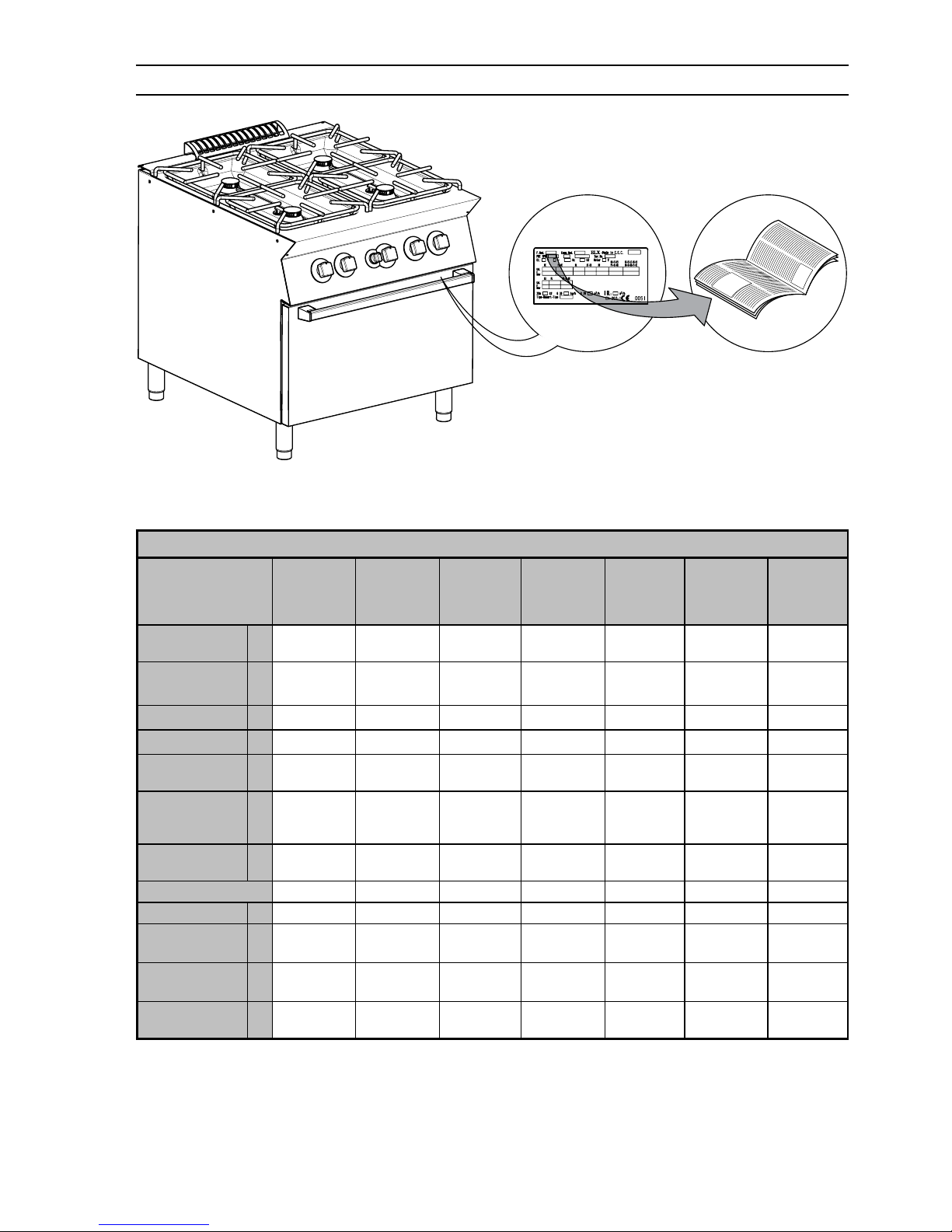
II. DATAPLATE and TECHNICAL DATA
IMPORTANT
This manual contains information relevant to various appliances. See the appliance dataplate located under the
control panel in order to identify the appliance (see fig. above).
TABLE A - Gas/electrical appliance technical data
MODELS
+7GCGD2C00
E7GCGD2C0A
Z7GCGD2C0A
400mm
+7GCGH4C00
E7GCGH4C0A
Z7GCGH4C0A
800mm
+7GCGL6C00
E7GCGL6C0A
Z7GCGL6C0A
1200mm
+7GCGH4CG0
E7GCGH4CGA
Z7GCGH4CGA
800mm
+7GCGL6C10
E7GCGL6C1A
Z7GCGL6C1A
1200mm
+7GCGH4CE0
E7GCGH4CEA
Z7GCGH4CEA
800mm
+7GCGL6C20
E7GCGL6C2A
Z7GCGL6C2A
1200mm
TECHNICAL DATA
Power supply
voltage
V
- - - - 400 400
Electrical power
absorbed
kW
- - - - 6 6
Phases N°
- - - - 3N 3N
Frequency Hz
- - - - 50/60 50/60
ISO 7/1
connection
Ø
1/2” 1/2” 1/2” 1/2” 1/2” 1/2” 1/2”
Cooktop burners
Ø60
(5.50-1.4 kW)
Nr.
2 4 6 4 6 4 6
Cooktop nominal
heat output
kW
11 22 33 22 33 22 33
Type of construction
A1 A1 A1 A1 A1 A1 A1
Oven type -
- - - Gas Gas Electric Electric
Oven max. heat
output
kW
- - - 6 6 - -
Oven min. heat
output
kW
- - - - - - -
Nominal heat
output
kW
11 22 33 28 39 22 33
Page 3
20
TABLE A - Electrical appliance technical data
MODELS
+7ECED2R00
400mm
+7ECEH4R00
+7ECEH4Q00
800mm
+7ECEL6R00
1200mm
+7ECEH4RE0
+7ECEH4QE0
800mm
TECHNICAL DATA
Power supply voltage V
380-400 380-400 380-400 380-400
Phases N°
3N 3N 3N 3N
Frequency Hz
50/60 50/60 50/60 50/60
Cooktop hot-plates
(2.6 kW)
Nr.
2 4 6 4
Cooktop hot-plate
max. power
kW
5,2 10,4 15,6 10,4
Oven max. power kW
- - 6
Nominal max. power kW
4,5 - 5,2 9 - 10,4 13,5-15,6 14,6 - 16,4
Power cable section
mm
2
4 4 6 4
TABLE A - Gas/electrical appliance technical data
MODELS
+7GCGD2C0A
400mm
+7GCGH4C0A
800mm
+7GCGH4CGA
+7GCGL6C1A
800mm
+7GCGH4CEA
+7GCGL6C2A
800mm
+7GCGL6C0A
1200mm
+7GCGH4CEN
800mm
+7GCGI6CL0
+7GCGI6CLA
900mm
TECHNICAL DATA
Power supply
voltage
V
- - - 400 230 -
Electrical power
absorbed
kW
- - - 6 6 -
Phases N°
- - - 3N 3 -
Frequency Hz
- - - 50/60 50/60 -
ISO 7/1
connection
Ø
1/2” 1/2” 1/2” 1/2” 1/2” 1/2” 1/2”
Cooktop
burners Ø60
(5.50-1.4 kW)
Nr.
2 4 4 4 6 4 6
Cooktop
nominal heat
output
kW
11 22 22 22 33 22 33
Type of construction
A1 A1 A1 A1 A1 A1 A1
Oven type -
- - Gas Electric - Electric Gas
Oven max. heat
output
kW
- - 6 - - - 9
Oven min. heat
output
kW
- - - - - - -
Nominal heat
output
kW
11 22 28 22 33 22 42
Page 4
21
TABLE A - Electrical appliance technical data
MODELS
+7ECED2R0N
400mm
+7ECEH4R0N
+7ECEH4Q0N
800mm
+7ECEH4REN
+7ECEH4QEN
800mm
+7ECMD2R05
400mm
+7ECMD2R06
400mm
TECHNICAL DATA
Power supply voltage V
230 230 230 400 440
Phases N°
3 3 3 3 3
Frequency Hz
50/60 50/60 50/60 50/60 50/60
Cooktop hot-plates
(2.6 kW)
Nr.
2 4 4 2 2
Cooktop hot-plate max. power kW
5,2 10,4 10,4 5,2 5,2
Oven max. power kW
- - 6 - -
Nominal max. power kW
4,5 - 5,2 9 - 10,4 14,6 - 16,4 4,5 - 5,2 4,5 - 5,2
Power cable section
mm
2
4 4 4 4 4
TABLE A - Electrical appliance technical data
MODELS
+7ECMH4RE5
+7ECMH4QE5
800mm
+7ECMH4RE6
+7ECMH4QE6
800mm
+7ECML6Q25
800mm
+7ECML6Q26
800mm
TECHNICAL DATA
Power supply voltage V
400 440 400 440
Phases N°
3 3 3 3
Frequency Hz
50/60 50/60 50/60 50/60
Cooktop hot-plates
(2.6 kW)
Nr.
4 4 4 4
Cooktop hot-plate max. power kW
10,4 10,4 10,4 10,4
Oven max. power kW
6 6 6 6
Nominal max. power kW
14,6 - 16,4 14,6 - 16,4 14,6 - 16,4 14,6 - 16,4
Power cable section
mm
2
4 4 4 4
Page 5
22
III. GENERAL INSTRUCTIONS
• Carefully read the instruction handbook before using the appliance.
• After installation keep the instruction handbook for future consultation.
• FIRE HAZARD - Keep the area around the appliance clear and free from combustible materials. Do not
keep flammable materials in the vicinity of the appliance.
• Install the appliance in a well-ventilated place to avoid the creation of dangerous mixtures of unburnt
gases in the room.
• Air recirculation must take in account the air necessary for combustion, 2 m³/h/kW gas power, and also
the “well-being” of those working in the kitchen.
Inadequate ventilation causes asphyxia. Do not obstruct the ventilation system of the place where the
appliance is installed. Do not obstruct the vents or ducts of this or other appliances.
• Place emergency telephone numbers in a visible position.
• Installation, maintenance and conversion to another type of gas must only be carried out by qualified personnel authorised by the
manufacturer. For assistance, contact an authorised technical centre. Demand original spare parts.
• This equipment is designed for cooking food. It is intended for industrial use. Any other use is to be considered improper.
• This appliance is not intended for use by people (including children) with limited physical, sensory or mental abilities or without
experience and knowledge of it, unless they are supervised or instructed in its use by a person responsible for their safety.
• The appliance must be used by trained personnel. Do not leave the appliance unattended when operating.
• Turn the appliance off in case of fault or poor operation.
• Do not use products (even if diluted) containing chlorine (sodium hypochlorite, hydrochloric or muriatic
acid, etc.) to clean the appliance or the floor under it. Do not use metal tools to clean steel parts (wire
brushes or Scotch Brite type scouring pads).
• Do not allow oil or grease to come into contact with plastic parts.
• Do not allow dirt, fat, food or other residuals to form deposits on the appliance.
• Do not clean the appliance with direct jets of water.
• The symbol L given on the product indicates that it should not be considered domestic waste, but must
be correctly disposed of in order to prevent any negative consequences for the environment and the health
of persons.
For further information regarding the recycling of this product, contact the product agent or local dealer, the
after-sales service or the local body responsible for waste disposal.
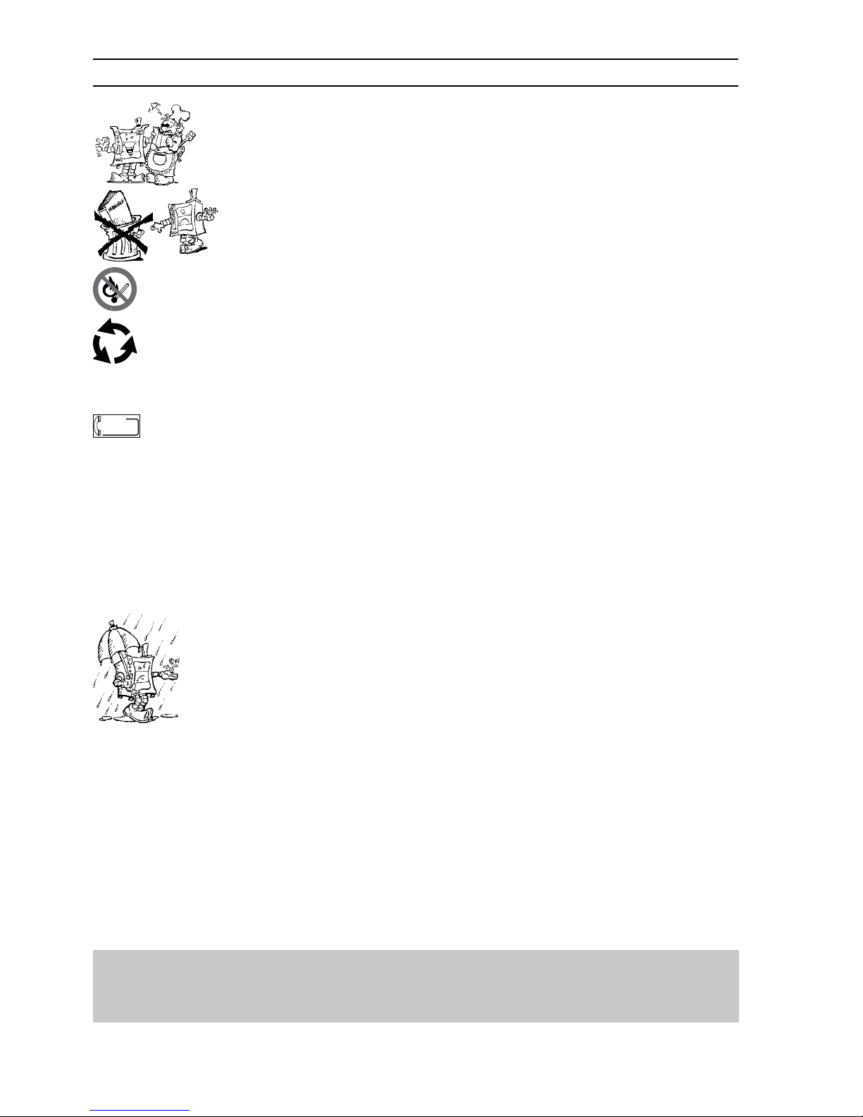
• Warnings:
• Do not store or use gasoline or other flammable vapours, liquids or items in the vicinity of this or any other appliance.
• Do not spray aerosols in the vicinity of this appliance while it is in operation.
• Never check for leaks with an open flame
• The appliance is not suitable for a marine environment.
.
Failure to observe the above can compromise the safety of the appliance. Failure
to observe the above invalidates the warranty.
sos
Page 6

23
IV. THE ENVIRONMENT
1. PACKING
Packing materials are environment friendly and can
be stored without risk, or burned in a special waste
incineration plant.
Recyclable plastic components are marked with:
Polyethylene: outer wrapping, instruction booklet
bag, gas nozzle bag.
Polypropylene: roof packing panels, straps.
Polystyrene foam: corner protectors.
2. USE
Our appliances offer high performance and efficiency. To
reduce consumption of electricity, water or gas, do not use
the appliance empty or in conditions that compromise optimal
efficiency (e.g. with doors or lids open, etc.); the appliance
is used in a well-ventilated place to avoid the creation of
dangerous mixtures of unburnt gases in the room. Whenever
possible, pre-heat only before use.
3. CLEANING
In order to reduce the emission of pollutants into the environment, clean the appliance (externally and when necessary
internally) with products that are more than 90% biodegradable (for further information, see chap. V “CLEANING”).
4. DISPOSAL
Do not disperse in the environment. Our appliances are manufactured using more than
90% (in weight) recyclable metals (stainless
steel, iron, aluminium, galvanised sheet,
copper, etc.).
Make the appliance unusable by removing
the power cable and any compartment or cavity closing mechanisms (when present) in order to avoid the risk of someone
becoming closed inside.
V. INSTALLATION
• Carefully read the installation and maintenance procedu-
res given in this instruction manual before installing the
appliance.
• Installation, maintenance and conversion to
another type of gas must only be carried out
by qualified personnel authorised by the manufacturer.
• Failure to observe the correct appliance installation, con-
version and modification procedures can cause damage
to the appliance, danger to persons and invalidates the
Manufacturer’s warranty.
PP
PS
1. REFERENCE STANDARDS
• Install the appliance in accordance with the safety regulations and local laws of the country where used.
• AUSTRALIA: this appliance shall be installed only by
authorised persons and in accordance with the manufacturer’s installation instructions, local gas fitting regulations,municipal building codes, electrical wiring regulations,
local water supply regulations, AS5601-gas installation,
health authorites and any other statutory regulations.
2. UNPACKING
IMPORTANT!
Immediately check for any damage caused during transport.
• The forwarder is responsible for the goods during transport
and delivery.
• Inspect the packing before and after unloading.
• Make a complaint to the forwarder in case of visible or
hidden damage, reporting any damage or shortages on
the dispatch note on delivery.
• The driver must sign the dispatch note: The forwarder
can reject the claim if the dispatch note is not signed (the
forwarder can provide the necessary form).
• Unpack, taking care not to damage the equipment. Wear protective gloves.
• Carefully remove the protective film from metal surfaces
and clean any traces of glue with a suitable solvent.
• For hidden damage or shortages becoming apparent only
after unpacking, request the forwarder for inspection of the
goods within and not later than 15 days of delivery.
• Keep all the documentation contained in the packing.
3. POSITIONING
• Handle the equipment with care in order to avoid damage
or danger to persons. Use a pallet for handling and positioning.
• The installation diagram given in this instruction manual
gives the appliance dimensions and the position of connections (gas, electricity, water). Check that they are available and ready for making all the necessary connections.
• The appliance can be installed separately or combined
with other appliances of the same range.
• The appliances are not designed for built-in installation.
Leave at least 10 cm between the appliance and side or
rear non-combustible walls.
Leave at least 25 cm between the appliance and side or
rear walls made from combustible materials.
• Suitably insulate surfaces that are at distances less than
those recommended.
• Maintain an adequate distance between the appliance
and any combustible walls. Do not store or use flammable
materials and liquids near the appliance.
• Leave an adequate space between the appliance and
any side walls in order to enable subsequent servicing or
maintenance operations.
• Check and if necessary level the appliance after positioning. Incorrect levelling of the appliance can affect
combustion and cause malfunctioning.
PE
Page 7

24
3.1. COMBINING APPLIANCES
• (Fig.1A) Remove the control panels of the appliances by
undoing the 4 fixing screws.
• (Fig.1B) Remove the fixing screw nearest the control panel,
from each side to be joined.
• (Fig.1D) Bring the appliances together and level them by
turning the feet until the tops match.
• (Fig.1C) Turn one of the two plates inside the appliances
180º.
• (Fig.1E) From inside the control panel of the same appliance, join them at the front side, screwing one TE M5x40
screw (supplied) on the opposite insert.
3.2. FLOOR FIXING
To avoid accidental tipping of built-in half-module appliances installed
separately, fix them to the floor carefully following the instructions
enclosed with the corresponding accessory (F206136).
3.3 INSTALLATION ON BRIDGE, CANTILEVER FRAME
OR CEMENT PLINTH
Carefully follow the instructions enclosed with the corresponding accessory.
Follow the instructions supplied with the optional product
chosen.
3.4. SEALING GAPS BETWEEN APPLIANCES
Follow the instructions supplied with the optional sealing
paste pack.
3.5. ADjUSTMENT G9
Once installed in order to optimize the door closure operate
using a screwdriver to adjust the spring lock’s height (press
the spring lock down fully and turn clockwise to lower, anticlockwise otherwise).
4. FUME EXHAUST
For Australia, ventilation must be in accordance with
australian building codes and kitchen exhaust hoods must
comply with AS/NZS1668.1 and AS 1668.2
4.1. TYPE “A1” APPLIANCES
Position type “A1” appliances under an extraction hood to
ensure removal of fumes and steam produced by cooking.
• SUB CLAUSE 4.1 is not relevant for australian standard.
5. CONNECTIONS
• Any installation work or maintenance to the supply system (gas, electricity, water) must only be
carried out by the utility company or an authorised
installation technician.
• See the appliance dataplate for the product code.
• See the installation diagram for the type and position of
appliance connections.
5.1. GAS APPLIANCES
IMPORTANT! Ensure that the available gas supply matches
the data label; to convert the gas type, follow the instructions
in par. 5.1.6. in this chapter.
5.1.1. BEFORE CONNECTING
• Make sure the appliance is arranged for the type of gas to
be used. Otherwise, carefully follow the instructions given
in the chapter: “Gas appliance conversion / adjustment”.
• Fit a rapid gas shut-off cock/valve ahead of each appliance.
Install the cock/valve in an easily accessed place.
• Clean the pipes to remove any dust, dirt or foreign matter
which could block the supply.
• The gas supply line must ensure the gas flow necessary
for full operation of all the appliances connected to the
system. A supply line with insufficient flow will affect correct operation of the appliances connected to it.
Page 8

25
5.1.2. CONNECTION
• See the installation diagram for the position of the gas
connection on the bottom of the appliance.
• Remove the protective plastic cover (if present) from the
appliance gas union before connecting.
• After installation, use soapy water to check connections
for leaks.
• The gas conection is male 1/2” BSP.
5.1.3. SUPPLY PRESSURE CHECK
Make sure the appliance is suitable for the type of gas available, according to that given on the dataplate (otherwise,
follow the instructions of par. “Conversion to another type
of gas”). The supply pressure must be measured with the
appliance operating, using a manometer (min. 0.1 mbar).
• Remove the control panel.
• Remove retaining screw “N” from the pressure point and
connect the manometer “O” (fig. 2A-2B).
• Compare the value read on the manometer with that given
in table B (see handbook Appendix)
• If the manometer gives a pressure outside the range of
values in table B, do not start the appliance, and consult
the gas company.
5.1.4 GAS PRESSURE REGULATOR
If the gas pressure is higher than that specified or is difficult
to regulate (not stable), install a gas pressure regulator (accessory code 927225) in an easily accessed position ahead
of the appliance.
The pressure regulator should preferably be fitted horizontally,
to ensure the right outlet pressure:
• “1” connection side gas from mains.
• “2” pressure regulator;
• “3” connection side gas towards the appliance;
The arrow on the regulator (
) shows the gas flow
direction.
3
1
2
AUSTRALIA: the gas pressure regulator supplied with the
appliance must be fitted to the appliance inlet. Adjust the test
point pressure with all hob burners operating at maximum
setting as follow:
- 1.0 KPa for Natural gas
- 2.65 KPa for Propane gas
NB! These models are designed and certified for use with
natural or propane gas.
5.1.5. CHECKING THE PRIMARY AIR SUPPLY
When the primary air supply is correctly adjusted, the flame
does not “float” with burner cold and there is no flareback
with burner hot.
•
Undo screw “A” and position aerator “E” at distance “H” given
on the Table B, retighten screw “A” and seal with paint (fig. 3A).
5.1.6. CONVERSION TO ANOTHER TYPE OF GAS
“Technical data/gas nozzles” Table B gives the type of nozzles
to be used when replacing those installed by the manufacturer
(the number is stamped on the nozzle body).
At the end of the procedure, carry out the following check-list:
Check Ok
• burner nozzle/s replacement
• correct adjustment of primary air supply to
burner/s
• pilot nozzle/s replacement
• minimum flame screw/s replacement
• correct adjustment pilot/s if necessary
• correct adjustment of supply pressure
(see technical data/gas nozzles table)
• apply sticker (supplied) with data of new gas type
used
5.1.6.1 REPLACING THE MAIN BURNER NOZZLE
(cooktop)
• Unscrew nozzle “C” and replace it with the corresponding
nozzle for the selected gas (Table. B, fig.3B) complying
with that given in the following table.
• The nozzle diameter is given in hundredths of mm on the
nozzle body.
• Fully retighten nozzle “C”.
5.1.6.2 REPLACING THE PILOT BURNER NOZZLE
(cooktop)
• Undo screw coupling “H” and replace nozzle “G” with one
suitable for the gas type (Table B, fig.3C).
• The nozzle identification number is given on the nozzle
body.
• Retighten screw coupling “H”.
5.1.6.3 REPLACING THE MINIMUM FLAME SCREW
(cooktop)
• Unscrew minimum flame screw “M” from the cock and
replace it with one suitable for the type of gas (screw down
fully) (Table B, fig.2B).
5.1.6.4 REPLACING THE MAIN BURNER NOZZLE (oven)
• Remove the oven floor.
• Unscrew nozzle “F” (Table B, fig. 3A).
• Remove the nozzle and aerator.
• Replace nozzle “F” with the corresponding nozzle for the
selected gas, according to that given in the table B.
• The nozzle diameter is given in hundredths of mm on the
nozzle body.
• Insert nozzle “F” in aerator “E”, then fit the two assembled
components in their position, screwing the nozzle down tightly.
Page 9

26
5.1.6.5 REPLACING THE PILOT BURNER NOZZLE
(oven)
• Undo screw coupling “H” and replace nozzle “G” with one
suitable for the gas type (Table B, fig.3D).
• The nozzle diameter is given in hundredths of mm on the
nozzle body.
• Retighten coupling “H”.
5.1.6.6 REPLACING THE ADjUSTMENT SPRING OF
THE PRESSURE REGULATOR
• Replace the spring of the pressure regulator with one
suitable for the gas pressure type given in table B (see
handbook Appendix) as follows:
- Remove the seal cap, seal cap gasket, adjusting screw
and the spring.
- Insert the new spring and replace the adjusting screw.
- Connect a pressure gauge to the appliance’s test point
pressure (fig. 2A/2B).
- Ignite the appliance’s burners so to have the maximum
gas consumption.
- Regulate the adjustment screw until the pressure gauge
shows the working pressure value (section 5.1.4 Gas
pressure regulator).
- Replace the seal cap and gasket and screw tightly closed.
- Remove the pressure gauge and close the test point
pressure.
- Prior to operation, test the gas pressure regulator for leaks.
5.2. ELECTRIC APPLIANCES
5.2.1. ELECTRICAL CONNECTION (Fig. 4A - Table A)
IMPORTANT! Before connecting, make sure the mains voltage
and frequency match that given on the dataplate.
• To access the terminal board, remove the appliance control panel by undoing the fixing screws (fig. 4A 1-2).
• Connect the power cable to the terminal board as shown
in the wiring diagram attached to the appliance.
• Secure the power cable with the cable gland.
IMPORTANT! The manufacturer declines any liability if the
safety regulations are not respected.
5.2.2. POWER CABLE
Unless otherwise specified, our appliances are not equipped
with a power cable. The installer must use a flexible cable
having characteristics at least equivalent to H05RN-F rubber-insulated type cables. Protect the cable section outside
the appliance with a metal or rigid plastic pipe.
5.2.3. CIRCUIT BREAKER
Install a circuit breaker ahead of the appliance. Contact opening distance and maximum leakage current must comply
with current regulations.
5.3. EQUIPOTENTIAL NODE AND EARTH
CONNECTION
Connect the appliance to an earth; it must be included in
an equipotential node by means of the screw located at the
front right under the frame. The screw is marked with the
symbol
.
6. SAFETY THERMOSTAT
Some of our appliance models use a safety thermostat that
cuts in automatically when temperatures exceed a set value,
shutting off the gas supply (gas appliances) or the electricity
(electric appliances).
6.1. RESET
• Wait until the appliance has cooled down: a suitable tem-
perature for resetting is approx. 90°C.
• Press the red button on the safety thermostat body.
IMPORTANT! If resetting requires the removal of a protective
part (e.g. control panel) this must be done by a specialised
technician. Tampering with the safety thermostat invalidates
the warranty.
7. BEFORE LEAVING
Check all connection for gas leaks with soap and water. Do
not use a naked flame for detecting leaks. Ignite all burners
both individually and combined to ensure correct operation of
gas valves, burners and ignition. Turn gas taps to low flame
for each burner, individually and separately, when satisfied
with the appliance, please, instruct the user on the correct
method of operation. In case the appliancefails to operate
correctly after all checks have been carried out, refer to the
authorised service provider.
Page 10

27
8. HANDRAIL
Marine appliances are equipped with a front handrail that can
be fitted by drilling the shelf according to the following diagram
23.5
60
52.5
=
B
A
A
=
52.5
A
32.6 (*)
27.2 (**)
58.3
35.6
23.5
60
A
32.6
8.1. INSTALLATION OF HANDRAIL
8.1.1 PREPARATION FOR INSTALLING ACCESSORY:
• Prepare the equipment by drilling the edge of the top (make
ø6 holes) at points “A”. For 1200mm and 1600mm appliances
also drill at point “B”;
8.1.2 ZANUSSI HANDRAIL
• Screw supports “D” on handrail “C” and insert them at the
holes prepared.
• Insert reinforcement plate “R” and fix the supports “S” with
the nuts and washer.
S
C
R
1a
8.1.3 ELECTROLUX HANDRAIL
• Fix supports “A” to the edge of the top at the holes prepared,
with screw “B”, plate “C” and respective nuts and washer, as
shown in the figure.
• Fit handrail “D” on support “A” and secure it with screw “E”,
as shown in the figure.
C
B
A
D
E
1c
Page 11

28
IV. INSTRUCTIONS FOR THE
USER
1. COOKTOP USE
1.1. GAS MODELS
Lighting cooktop burners
The gas cock control knob has 4 positions:
V Off position
C pilot ignition
A max. flame
B min. flame
H
Lighting
• Press and turn knob “H” to “pilot on”.
Press the knob down fully and hold a flame to the pilot in
order to light. Hold the knob down for about 20 seconds;
when released, the pilot flame must remain lit. If it does
not, repeat the operation.
• To light the main burner, turn the knob from “pilot on” to
“max. flame”.
• For the minimum flame, turn the knob from “max. flame”
to “min. flame”.
Turning off
• Turn the knob from “max. flame” or “min. flame” to “pilot
on”.
• To shut off the pilot, press the knob lightly and turn it to
“off”.
NB: Incorrect positioning of the flame spreader can create
problems in combustion.
• Before lighting the burners make sure the flame spreaders
are turned to the stop position.
1.2. ELECTRIC MODELS
• Equipped with rapid heating electric hot-plates each of 2.6
kW power.
• To ensure long life of the hot-plates, observe the following:
- use flat-bottomed pots;
- do not leave the hot-plates switched on without pots
or with empty pots.
- do not spill cold liquids on the hot-plate when hot.
H
Switching on
• Turn the appliance on at the main switch.
• Turn control knob “B” of the required hot-plate, to one of
the six available positions marked on the control panel,
bearing in mind that “1” corresponds to minimum power
and “6” corresponds to maximum power.
Lighting up of green indicator “A” signals that the corre-
sponding hot-plate is on.
• To adjust hot-plate heat, turn the knobs firstly to “6”; on
reaching maximum cooking or boiling temperature, turn
the knob to a lower setting.
Turning off
Turn the control knobs to “0”.
Page 12

29
2. OVEN USE
2.1. GAS MODELS
The thermostatic valve control knob has the following positions:
Off position
pilot ignition
pilot
burner
L
270
250
230
210
190
170
150
110
270
250
230
210
190
170
150
110
I
• Lightly press knob “I” and turn it a few degrees anticlockwise to release it.
• Press down fully and turn it to “pilot ignition”; a click will
indicate sparking.
• Keep knob “I” pressed and turn it to “pilot”, holding it in that
position for about 15-20 seconds to allow the gas to reach
the pilot burner (pilot ignition) and the thermocouple to heat.
• With the pilot lit, turn knob “l” from “pilot” to “burner” to light
the latter.
• At this point, knob “L” can be used to select the required
temperature.
WARNING: the knob must remain on “burner” position when
operating the oven. Do not operate the oven with this knob
“I” in any other position.
NB: The appliance’s oven should only be operated with Knob
“I” turned to “burner” position.
2.1.1 ITERLOCK
The oven gas valve has an interlock device which prevents
immediate re-lighting (for about 40 seconds) of the oven
in the event it is accidentally turned off. This ensures the
flow of gas which has possibly accumulated inside the
oven, and better safety.
Turning off
• Turn knob “I” clockwise to position “pilot”.
• Then press the knob down and turn it to position “Off“.
Note: if removing knob “L” for cleaning, always turn knob fully
clockwise to the lowest setting and replace the knob so that
the mark on the knob aligns with the lowest temperature
marking. Failure to replace the knob correctly will result in
inaccurate oven temperature.
2.2. ELECTRIC MODELS
The heating elements are controlled by a 4-position selector
knob “D”, whereas the oven temperature is controlled by a
thermostat “E”.
Use the selector knob to choose the most suitable type
of heating, using the appropriate heating elements:
O
1
Off position
“appliance On” position
upper and lower heating elements
upper heating element
lower heating element
D
E
G
0
1
2
3
4
5
6
0
1
2
3
4
5
6
0 0
140
170
190
210
230
250
280
320
0
1
2
3
4
5
6
0
1
2
3
4
5
6
A
0
0
200
220
240
260
300
280
100
120
140
160
180
NB:
The oven door must be closed for all types of cooking.
Switching on
Turn heating element control knob “D” to the required setting.
Lighting up of green indicator “A” signals that the power is on.
Turn thermostat knob “E” to the required cooking temperature
(between 100 and 300 °C). Lighting up of yellow indicator “G”
signals that the heating elements are on; it goes off when the
oven reaches the set temperature.
Switching off
Turn the control knobs to the off position “0”. Turn off the
electrical switch installed ahead of the appliance.
Page 13

30
V. CLEANING
CAUTION!
Before carrying out any cleaning operation, disconnect the
appliance from the power supply.
1. EXTERNAL PARTS
SATIN-FINISH STEEL SURFACES (daily)
• Clean all steel surfaces: dirt can be easily removed as
soon as it forms.
• Remove grime, fat and other cooking residuals from steel
surfaces when cool using soapy water, with or without detergent, and a cloth or sponge. Dry the surfaces thoroughly
after cleaning.
• In case of encrusted grime, fat or food residuals go over
with a cloth or sponge, wiping with the grain of the satin
finish, and rinsing often: rubbing in a circular motion combined with the particles of dirt on the cloth/sponge could
ruin the steel’s satin finish.
• Metal objects can ruin or damage the steel: ruined surfaces become dirty more easily and are more subject to
corrosion.
• Restore the satin finish if necessary.
SURFACES BLACKENED BY HEAT (when necessary)
Exposure to high temperatures can cause the formation of
dark marks. These do not constitute damage and can be
removed by following the instructions given in the previous
paragraph.
NB: Avoid dirtying the inside of the Venturi tubes.
The presence of dirt inside the appliance can obstruct the
nozzles, and thus affect the flame.
2. OTHER SURFACES
CAST IRON ELECTRIC HOT-PLATES
Clean the hot-plates with a damp cloth, then switch them on
for a few minutes to dry rapidly; lastly, lubricate them with
a light film of cooking oil. DO NOT pour cold liquids on the
hot-plates while they are hot.
IMPORTANT! With electric appliances, make sure no water
comes into contact with electrical components: water penetration can cause short circuiting and dissipation, tripping the
appliance’s protection devices.
3. PERIODS OF DISUSE
If the equipment is not going to be used for some time, take
the following precautions:
• Close cocks or main switches ahead of the appliances.
• Go over all stainless-steel surfaces vigorously with a cloth
moistened with paraffin oil in order to spread a protective
film.
• Periodically air the room.
• Have the appliance checked before using it again.
• To prevent too rapid evaporation of accumulated moisture
with consequent breakage of elements, switch electric
appliances on at minimum heat for at least 45 minutes
before reuse.
4. INTERNAL PARTS (every 6 months)
IMPORTANT! Operations to be carried out only by specialised technicians.
• Check the condition of internal parts.
• Remove any deposits of grime inside the appliance.
• Check and clean the discharge system.
NB ! In particular environmental conditions (e.g. intensive
use of the appliance, salty environment, etc.) the above cleaning should be more frequent.
Page 14

31
VI. MAINTENANCE
1. MAINTENENCE
All the components requiring maintenance are accessible
from the front of the appliance, after removing the control
panel and front panel. Disconnect the power supply before
opening the appliance
1.1 BRIEF TROUBLESHOOTING GUIDE
Even in normal appliance operating conditions, malfunctions
can occasionally occur.
- The pilot burner of open burners does not light
Possible causes:
• Insufficient pressure in gas pipes.
• Nozzle blocked.
• Faulty gas cock.
- The oven pilot burner does not light
Possible causes:
• Igniter not properly fixed or connected
• The piezoelectric ignition or igniter cable are damaged.
• Insufficient pressure in gas pipes
• Worn nozzle
• Faulty gas valve
- The pilot burner goes out when the “pilot ignition” knob is
released
Possible causes:
• The pilot burner is not heating the thermocouple sufficiently.
• Faulty thermocouple.
• The gas cock and/or gas valve knob is not being pressed
enough.
• Lack of gas pressure to the cock and/or valve.
• Faulty gas cock or gas valve.
- The pilot burner is still lit but the main burner does not light
Possible causes:
• Loss of pressure in gas supply pipe.
• Blocked nozzle or faulty gas cock or valve.
• Gas outlet holes on burner clogged.
- The oven temperature cannot be adjusted.
Possible causes:
• Faulty thermostat bulb.
• Faulty gas valve.
• Faulty electric thermostat.
• Electric safety thermostat tripped.
ABNORMAL OPERATION
Any of the following are considered to be abnormal operation
and may require servicing:
• incomplete ignition of the burner;
• yellow tipping of the burner flame;
• burner failing to remain alight;
• gas valves are difficult to turn;
• burner exitinguished by operation of oven door.
In case the appliance fails to operate correctly, contact the
authorised service provider in your area.
INSTRUCTIONS FOR REPLACING COMPONENTS (to be
carried out only by an authorised installer).
Remove the front panel to access:
GAS COCK
• Unscrew the pilot and thermocouple pipe, unscrew the
gas inlet and outlet connections.
• For installation carry out the same procedure in reverse order.
PILOT BURNER, THERMOCOUPLE, IGNITER ASSEMBLY
• To replace the igniter and thermocouple loosen the fixing
screws and remove the components.
• To replace the pilot burner undo the gas pipe, remove the
pilot burner assembly
• Replace the components, proceeding in reverse order to
refit the parts.
MAIN BURNER
• Unscrew the gas connection from the nozzle holder
• Undo the screws fixing the burner to the support
• Remove the pilot burner assembly by undoing the screws
• For installation carry out the same procedure in reverse order,
making sure that when positioning the burner the centering
pins, located at the back of the burner, enter their special seats
1.2 MAINTENENCE SCHEDULE
• It is reccommended the appliance is inspected and serviced by an authorized person at least every 12 months. For
this purpose it is reccommended to draw up a maintenece
contract.
AUSTRALIA
For service and spare parts, please contact:
Electrolux - Tom Stoddart Pty Ltd
Zanussi - JL Lennard Pty Ltd
 Loading...