


INSTALLATION, OPERATING AND MAINTENANCE INSTRUCTIONS
ISTRUZIONI DI INSTALLAZIONE, FUNZIONAMENTO E MANUTENZIONE
INSTRUCTIONS D'INSTALLATION, D'UTILISATION ET DE MAINTENANCE
INSTRUCCIONES DE INSTALACIÓN, USO Y MANTENIMIENTO
TAVOLI REFRIGERATI E FREEZER CON CONTROLLO ELETTRONICO
REFRIGERATED AND FREEZER COUNTERS WITH ELECTRONIC CONTROL
TABLES RÉFRIGÉRÉES ET FREEZERS À CONTRÔLE ÉLECTRONIQUE
MESAS REFRIGERADAS Y CONGELADOR CON CONTROL ELECTRÓNICO
USA Page 14 -28
IT Pagina 29 -43
FR Page 44 -58
ES Página 59 -73
PART NO. 595R 001 01
VERSION 2 2006.11
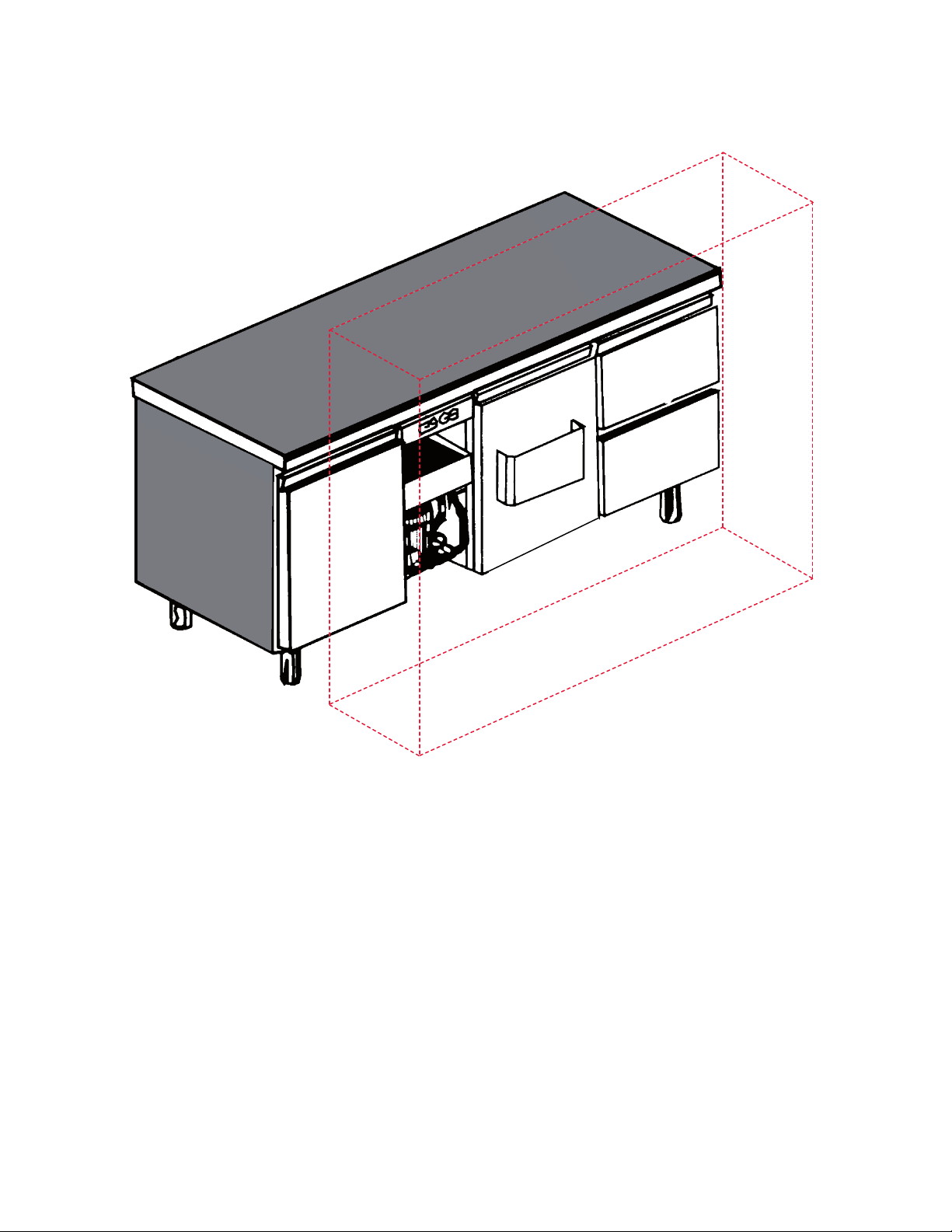
INSTALLATION DIAGRAM
SCHEMA D’INSTALLAZIONE
SCHÉMA D’INSTALLATION
DIAGRAMA DE INSTALACIÓN
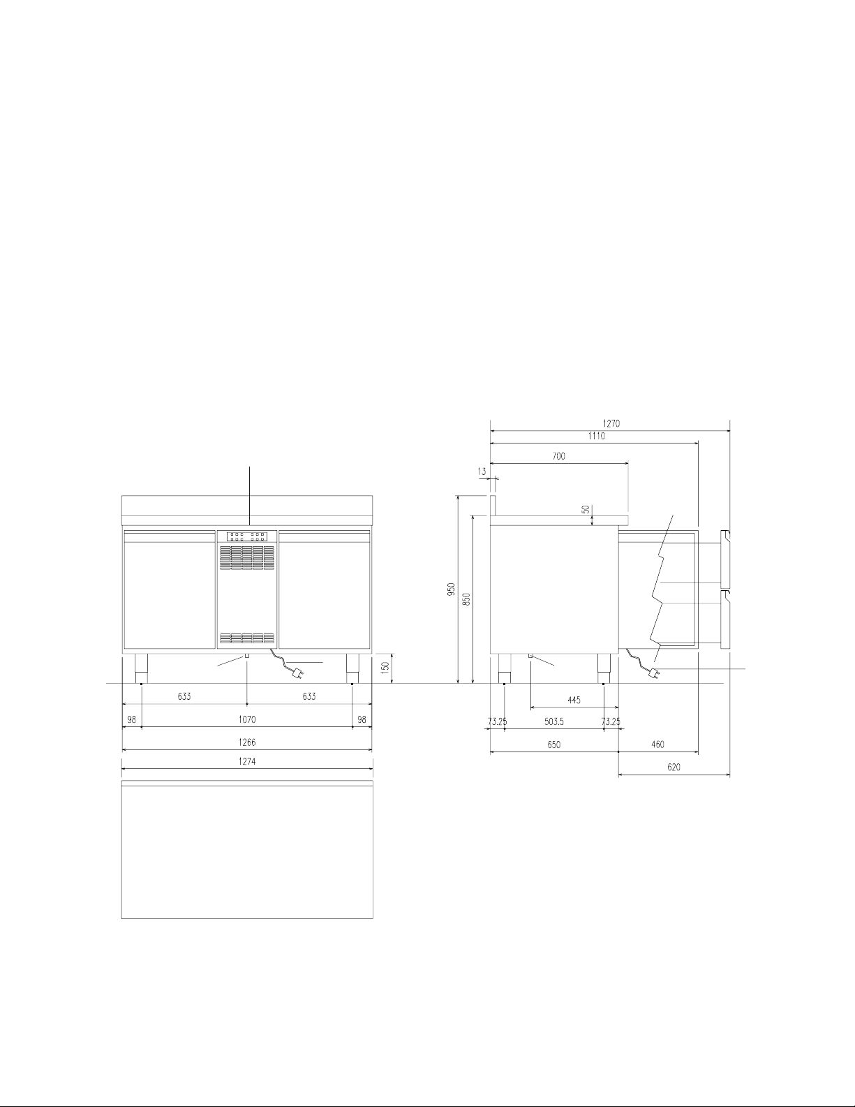
TAVOLO REFRIGERATO 2 VANI CON ALZATINA
2-COMPARTMENT REFRIGERATED COUNTER WITH
SHOULDER
TABLE RÉFRIGÉRÉE 2 COMPARTIMENTS AVEC BORD
REHAUSSÉ
MESA REFRIGERADA DE 2 COMPARTIMENTOS CON
COPETE
FRONT VIEW
VISTA FRONTALE
VUE DE FACE
VISTA FRONTAL
B
TAVOLO FREEZER 2 VANI CON ALZATINA
2-COMPARTMENT FREEZER COUNTER WITH
SHOULDER
TABLE RÉFRIGÉRÉE 2 COMPARTIMENTS AVEC BORD
REHAUSSÉ
MESA CONGELADOR DE 2 COMPARTIMENTOS CON
COPETE
SIDE VIEW
VISTA LATERALE
VUE LATÉRALE
VISTA LATERAL
A
C
A
I
TOP
PIANO
CI
VUE DE DESSUS
PLANO
2

USA
FR
A = MODULAR COMPARTMENT DESIGNED FOR SOLID
DOORS (WIRE SHELVES IN CELL) OR DRAWER UNIT
B = MODULAR COMPARTMENT DESIGNED FOR
REFRIG ERATING UNIT OR FREEZER
C = OUTLET FOR DRAINING OF LIQUIDS FROM CELL,
DIAMETER 0,69"/17,5 mm.
I = POWER SUPPLY CABLE, LENGTH 131,10"/3330 mm,
SCHUKO TYPE PLUG
IT
A = VANO MODULARE PREDISPOSTO PER PORTE
CIECHE (GRIGLIE PORTA VIVANDE IN CELLA) O
CASSETTIERA
A = COMPARTIMENT MODULAIRE PRÉDISPOSÉ POUR
PORTES NORMALES (CLAYETTES EN CELLULE) OU
BLOC TIROIRS
B = COMPARTIMENT MODULAIRE PRÉDISPOSÉ POUR
GROUPE FRIGORIFIQUE OU GROUPE
CONSERVATEUR
C = BONDE POUR L’ÉVACUATION DES LIQUIDES DE LA
CELLULE, DIAMÈTRE 0,69"/17,5 mm
I = CÂBLE D’ALIMENTATION LONGUEUR 131,10"/3330
mm, PRISE TYPE SCHUKO.
ES
A = COMPARTIMIENTO MODULAR PREPARADO PARA
PUERTAS CIEGAS (REJILLAS EN LA CÁMARA) O
CAJONERA
B = VANO MODULARE PREDISPOSTO PER GRUPPO
REFRIGERANTE O FREEZERS
C = PILETTA PER LO SCARICO LIQUIDI DELLA CELLA,
DIAMETRO 0,69"/mm 17,5.
I = CAVO D'ALIMENTAZIONE LUNGHEZZA 131,10"/3330
mm, PRESA TIPO SCUKO.
B = COMPARTIMIENTO MODULAR PREPARADO PARA
GRUPO REFRIGERANTE O CONGELADORES
C = DESAGÜE DE LÍQUIDOS DE LA CÁMARA, DIÁMETRO
0,69"/17,5 mm.
I = CABLE DE ALIMENTACIÓN 131,10"/3330 mm DE
LONGITUD, ENCHUFE TIPO SCHUKO.
3
INSTALLATION DIAGRAM
SCHEMA D’INSTALLAZIONE
SCHÉMA D’INSTALLATION
DIAGRAMA DE INSTALACIÓN
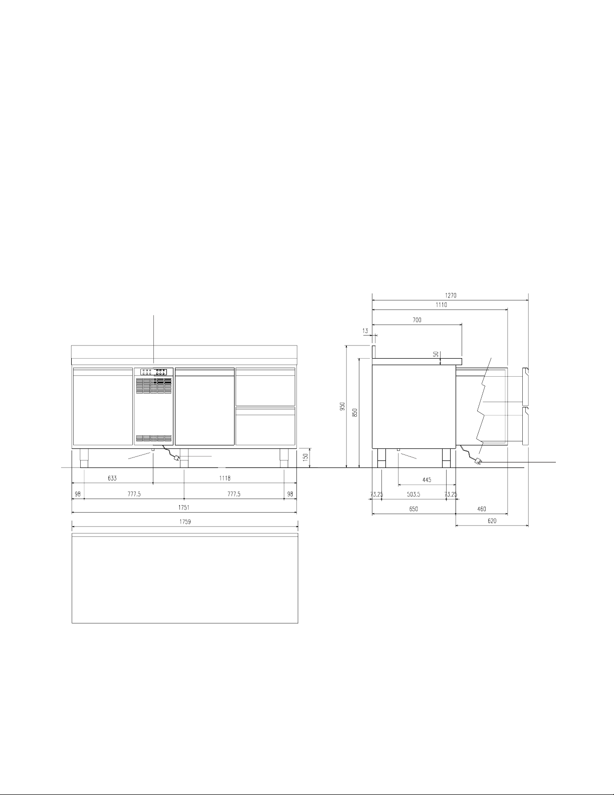
TAVOLO REFRIGERATO 3 VANI CON ALZATINA
3-COMPARTMENT REFRIGERATED COUNTER WITH
SHOULDER
TABLE RÉFRIGÉRÉE 3 COMPARTIMENTS AVEC BORD
REHAUSSÉ
MESA REFRIGERADA DE 3 COMPARTIMENTOS CON
COPETE
FRONT VIEW
VISTA FRONTALE
B
VUE DE FACE
VISTA FRONTAL
A
TAVOLO FREEZER 3 VANI CON ALZATINA3COMPARTMENT FREEZER COUNTER WITH
SHOULDER
TABLE RÉFRIGÉRÉE 3 COMPARTIMENTS AVEC BORD
REHAUSSÉ
MESA CONGELADOR DE 3 COMPARTIMENTOS CON
COPETE
SIDE VIEW
VISTA LATERALE
VUE LATÉRALE
VISTA LATERAL
AA
A
C
I
TOP
PIANO
C
VUE DE DESSUS
PLANO
I
4

USA
FR
A = MODULAR COMPARTMENT DESIGNED FOR SOLID
DOORS (WIRE SHELVES IN CELL) OR DRAWER UNIT
B = MODULAR COMPARTMENT DESIGNED FOR
REFRIG ERATING UNIT OR FREEZER
C = OUTLET FOR DRAINING OF LIQUIDS FROM CELL,
DIAMETER 0,69"/17,5 mm.
I = POWER SUPPLY CABLE, LENGTH 131,10"/3330 mm,
SCHUKO TYPE PLUG
IT
A = VANO MODULARE PREDISPOSTO PER PORTE
CIECHE (GRIGLIE PORTA VIVANDE IN CELLA) O
CASSETTIERA
A = COMPARTIMENT MODULAIRE PRÉDISPOSÉ POUR
PORTES NORMALES (CLAYETTES EN CELLULE) OU
BLOC TIROIRS
B = COMPARTIMENT MODULAIRE PRÉDISPOSÉ POUR
GROUPE FRIGORIFIQUE OU GROUPE
CONSERVATEUR
C = BONDE POUR L’ÉVACUATION DES LIQUIDES DE LA
CELLULE, DIAMÈTRE 0,69"/17,5 mm
I = CÂBLE D’ALIMENTATION LONGUEUR 131,10"/3330
mm, PRISE TYPE SCHUKO.
ES
A = COMPARTIMIENTO MODULAR PREPARADO PARA
PUERTAS CIEGAS (REJILLAS EN LA CÁMARA) O
CAJONERA
B = VANO MODULARE PREDISPOSTO PER GRUPPO
REFRIGERANTE O FREEZERS
C = PILETTA PER LO SCARICO LIQUIDI DELLA CELLA,
DIAMETRO 0,69"/mm 17,5.
I = CAVO D'ALIMENTAZIONE LUNGHEZZA 131,10"/3330
mm, PRESA TIPO SCUKO.
B = COMPARTIMIENTO MODULAR PREPARADO PARA
GRUPO REFRIGERANTE O CONGELADORES
C = DESAGÜE DE LÍQUIDOS DE LA CÁMARA, DIÁMETRO
0,69"/17,5 mm.
I = CABLE DE ALIMENTACIÓN 131,10"/3330 mm DE
LONGITUD, ENCHUFE TIPO SCHUKO.
5
INSTALLATION DIAGRAM
SCHEMA D’INSTALLAZIONE
SCHÉMA D’INSTALLATION
DIAGRAMA DE INSTALACIÓN
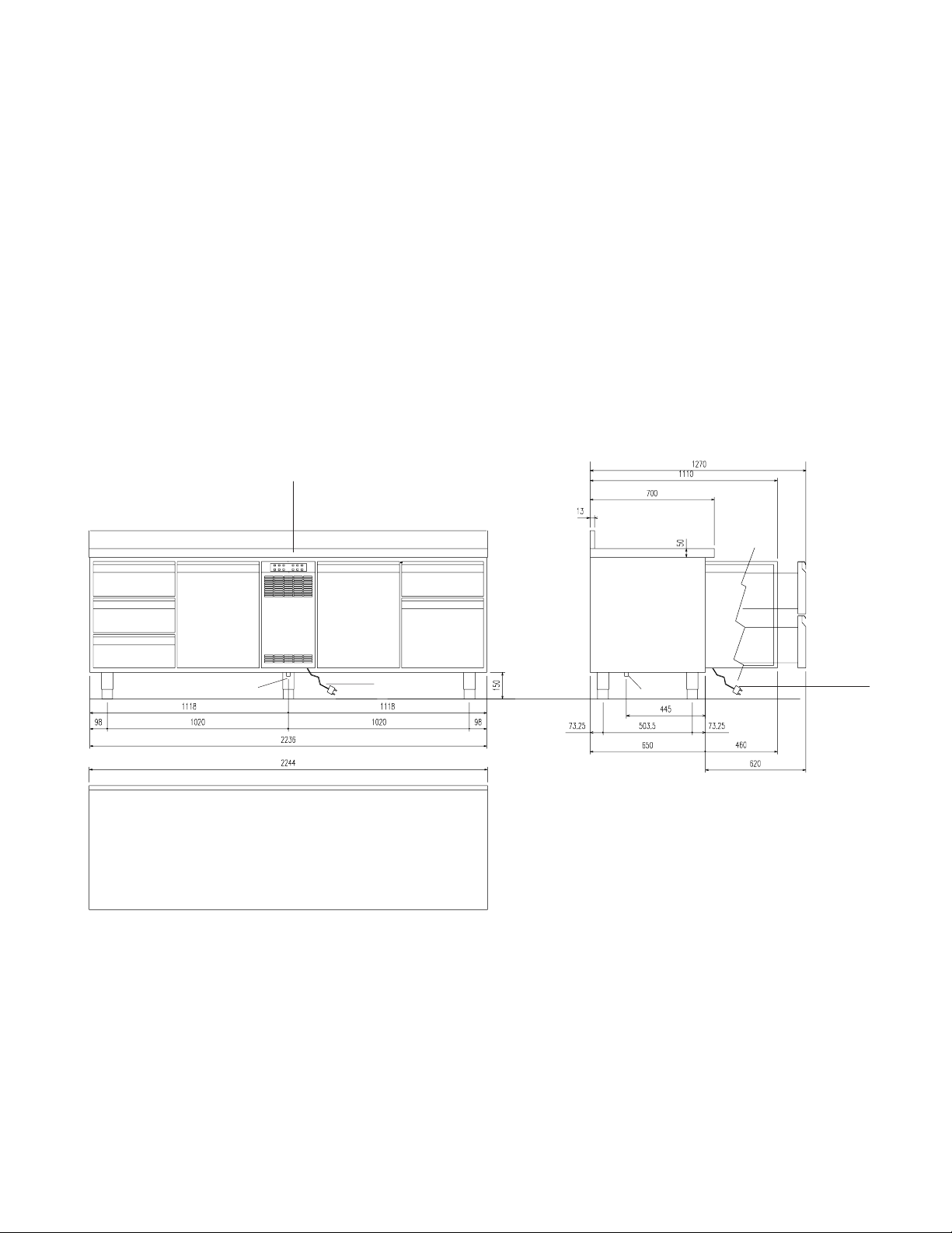
TAVOLO REFRIGERATO 4 VANI CON ALZATINA
4 COMPARTMENT REFRIGERATED COUNTER WITH
SHOULDER
FRONT VIEW
VISTA FRONTALE
A
A
VUE DE FACE
VISTA FRONTAL
B
A
A
A
TABLE RÉFRIGÉRÉE 4 COMPARTIMENTS AVEC BORD
REHAUSSÉ
MESA REFRIGERADA DE 4 COMPARTIMENTOS CON
COPETE
SIDE VIEW
VISTA LATERALE
VUE LATÉRALE
VISTA LATERAL
C
I
TOP
PIANO
C
VUE DE DESSUS
PLANO
I
6

USA
FR
A = MODULAR COMPARTMENT DESIGNED FOR SOLID
DOORS (WIRE SHELVES IN CELL) OR DRAWER UNIT
B = MODULAR COMPARTMENT DESIGNED FOR
REFRIG ERATING UNIT OR FREEZER
C = OUTLET FOR DRAINING OF LIQUIDS FROM CELL,
DIAMETER 0,69"/17,5 mm.
I = POWER SUPPLY CABLE, LENGTH 131,10"/3330 mm,
SCHUKO TYPE PLUG
IT
A = VANO MODULARE PREDISPOSTO PER PORTE
CIECHE (GRIGLIE PORTA VIVANDE IN CELLA) O
CASSETTIERA
A = COMPARTIMENT MODULAIRE PRÉDISPOSÉ POUR
PORTES NORMALES (CLAYETTES EN CELLULE) OU
BLOC TIROIRS
B = COMPARTIMENT MODULAIRE PRÉDISPOSÉ POUR
GROUPE FRIGORIFIQUE OU GROUPE
CONSERVATEUR
C = BONDE POUR L’ÉVACUATION DES LIQUIDES DE LA
CELLULE, DIAMÈTRE 0,69"/17,5 mm
I = CÂBLE D’ALIMENTATION LONGUEUR 131,10"/3330
mm, PRISE TYPE SCHUKO.
ES
A = COMPARTIMIENTO MODULAR PREPARADO PARA
PUERTAS CIEGAS (REJILLAS EN LA CÁMARA) O
CAJONERA
B = VANO MODULARE PREDISPOSTO PER GRUPPO
REFRIGERANTE O FREEZERS
C = PILETTA PER LO SCARICO LIQUIDI DELLA CELLA,
DIAMETRO 0,69"/mm 17,5.
I = CAVO D'ALIMENTAZIONE LUNGHEZZA 131,10"/3330
mm, PRESA TIPO SCUKO.
B = COMPARTIMIENTO MODULAR PREPARADO PARA
GRUPO REFRIGERANTE O CONGELADORES
C = DESAGÜE DE LÍQUIDOS DE LA CÁMARA, DIÁMETRO
0,69"/17,5 mm.
I = CABLE DE ALIMENTACIÓN 131,10"/3330 mm DE
LONGITUD, ENCHUFE TIPO SCHUKO.
7
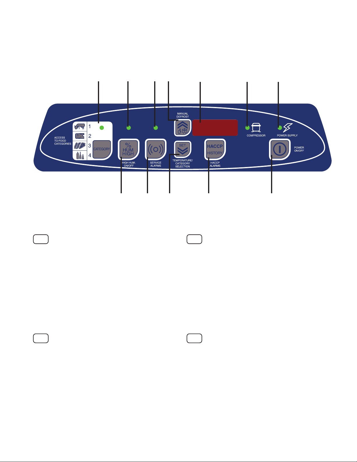
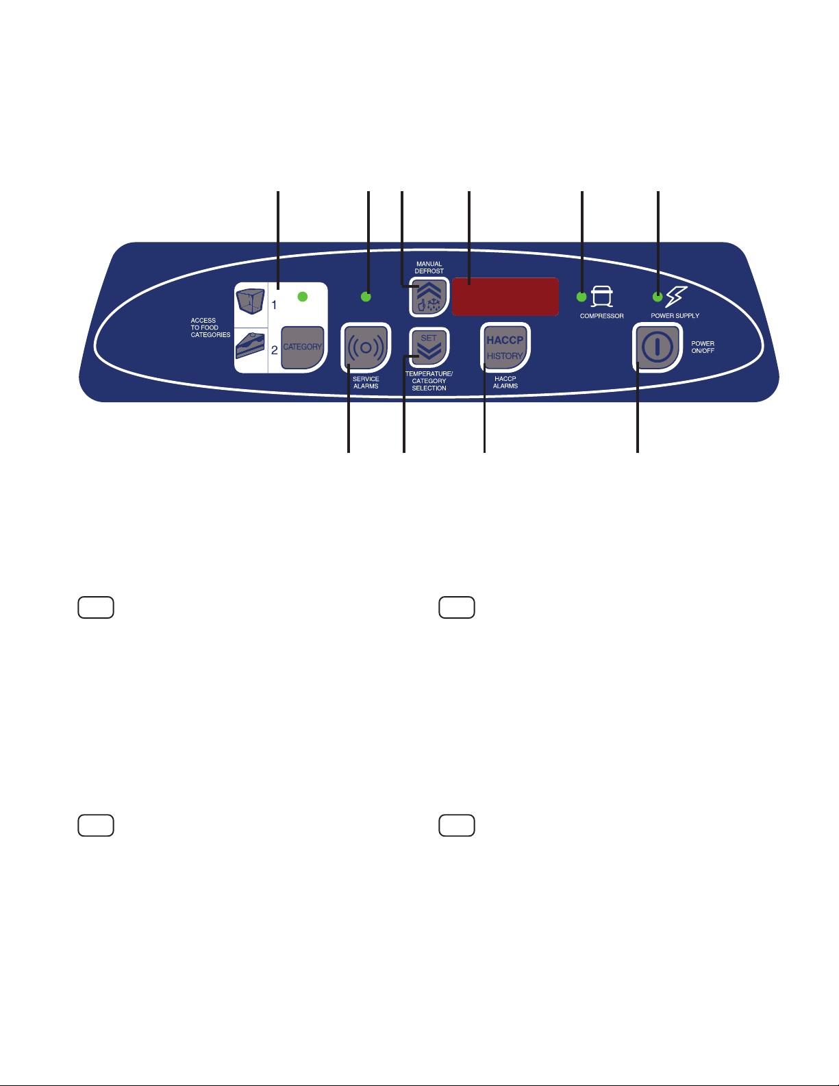
PANNEAU DE COMMANDE VERSION
"RÉFRIGÉRATEUR”
PANEL DE CONTROL VERSIÓN "FRIGORÍFICO”
Fig.1
USA
1
2a 3a 4 7 8 9
23
5
6
FR
10
1-Access to button for food categories
2 - High humidity ON/OFF button
2a - High humidity light
3 - Service alarms button
3a - Service alarms warning light
4 - Top button: manual defrost
5 - Bottom button: Temperature setting
/ Category selection
6 - HACCP alarms button
7 - Display
8 - Compressor status light
9 - Power status light
10 - ON/OFF button
IT
1 - Accesso al pulsante per le categorie degli alimenti
2 - Pulsante ON/OFF elevata umidità
2a - Spia elevata umidità
3 - Pulsante allarmi di servizio
3a - Spia allarmi di servizio
4 - Pulsante superiore: sbrinamento manuale
5 - Pulsante inferiore: Impostazione temperatura
/ Selezione categoria
6 - Pulsante allarmi HACCP
7 - Display
8 - Spia stato compressore
9 - Spia stato alimentazione
10 - Pulsante ON/OFF
1-Accès au bouton pour les catégories d'aliments
2 - Bouton ON/OFF humidité élevée
2a - Voyant humidité élevée
3 - Bouton alarmes de service
3a - Voyant alarmes de service
4 - Bouton supérieur : dégivrage manuel
5 - Bouton inférieur : Réglage température
/ Sélection catégorie
6 - Bouton alarmes HACCP
7 - Afficheur
8 - Voyant état compresseur
9 - Voyant état alimentation
10 - Bouton ON/OFF
ES
1 - Acceso a la tecla para las diferentes categorías de
alimentos
2 - Tecla ON/OFF de humedad elevada
2a - Indicador de humedad elevada
3 - Tecla de alarmas de servicio
3a - Indicador de alarmas de servicio
4 - Tecla superior: descongelación manual
5 - Tecla inferior: ajuste de temperatura/ selección de
categoría
6 - Tecla de alarmas HACCP
7 - Pantalla
8 - Indicador de estado del compresor
9 - Indicador de estado de la alimentación
10 - Tecla ON/OFF
8
“FREEZER” VERSION CONTROL PANEL
PANNELLO DI CONTROLLO VERSIONE
"CONGELATORE”
PANNEAU DE COMMANDE VERSION "CONGÉLATEUR”
PANEL DE CONTROL VERSIÓN "CONGELADOR”
Fig.2
1
3
2a
25
49
6
78
USA
1-Access to button for food categories
2 - Service alarms button
2a - Service alarms warning light
3 - Top button: manual defrost
4 - Bottom button: Temperature setting
/ Category selection
5 - HACCP alarms button
6 - Display
7 - Compressor status light
8 - Power status light
9 - ON/OFF button
IT
1 - Accesso al pulsante per le categorie degli alimenti
2 - Pulsante degli allarmi di servizio
2a - Spie allarmi di servizio
3 - Pulsante superiore: sbrinamento manuale
4 - Pulsante inferiore: Impostazione temperatura
/ Selezione categoria
5 - Pulsante allarmi HACCP
6 - Display
7 - Spia stato compressore
8 - Spia stato alimentazione
9 - Pulsante ON/OFF
FR
1-Accès au bouton pour les catégories d'aliments
2 - Bouton alarmes de service
2a - Voyants alarmes de service
3 - Bouton supérieur : dégivrage manuel
4 - Bouton inférieur : Réglage température
/ Sélection catégorie
5 - Bouton alarmes HACCP
6 - Afficheur
7 - Voyant état compresseur
8 - Voyant état alimentation
9 - Bouton ON/OFF
ES
1 - Acceso a la tecla para las diferentes categorías de
alimentos
2 - Tecla de las alarmas de servicio
2a - Indicadores de las alarmas de servicio
3 - Tecla superior: descongelación manual
4 - Tecla inferior: ajuste de temperatura/ selección de
categoría
5 - Tecla de alarmas HACCP
6 - Pantalla
7 - Indicador de estado del compresor
8 - Indicador de estado de la alimentación
9 - Tecla ON/OFF
9

CATEGORIES: TEMPERATURE AND HUMIDITY SETTING
CATEGORIE: TEMPERATURA E IMPOSTAZIONE
DELL'UMIDITA'
CATÉGORIES: TEMPÉRATURE ET
PROGRAMMATION DE L’HUMIDITÉ
CATEGORÍAS: TEMPERATURA Y CONFIGURACIÓN
DE LA HUMEDAD
REFRIGERATOR
VERSIONE A TEMPERATURA NEGATIVA
1 Pork & beef meat
2 Cheese, salted meat
3 Vegetables & fruit
4 Drinks
Fig.3
USA
1 - Poultry and game
2 - Red meats
3 - Cheeses and charcuterie
4 - Fruit and vegetables
5 - Drinks
IT
1 - Pollame e selvaggina
2 - Carni rosse
3 - Formaggi e salumi
4 - Verdura e frutta
5 - Bevande
VERSION À TEMPÉRATURE NÉGATIVE
VERSIÓN DE TEMPERATURA NEGATIVA
Temp. °C Humidity
0High
4Low
6High
8Low
FR
1 - Volailles et gibiers
2 - Viandes rouges
3 - Fromages et saucisses
4 - Légumes et fruits
5 - Boissons
ES
1 - Pollo y salvajina
2 - Carnes rojas
3 - Quesos y embutidos
4 - Verdura y fruta
5 - Bebidas
FREEZER
VERSIONE A BASSA TEMPERATURA
1
2
Fig.4
USA
1 - Frozen foods
2 - Frozen cakes/gateaux
IT
1 - Cibi congelati
2 - Torte gelato
VERSION À BASSE TEMPÉRATURE
VERSIÓN DE BAJA TEMPERATURA
Temp. °C Humidity
Frozen food
Ice cake
-18 =
-22 =
FR
1 - Aliments congelés
2 - Gâteaux glacés
ES
1 - Comidas congeladas
2 - Tortas/helado
10

INCORRECT DISTRIBUTION OF FOOD
CARICO NON CORRETTO DEGLI ALIMENTI
CHARGEMENT DES ALIMENTS INCORRECT
CARGA INCORRECTA DE LOS ALIMENTOS
CORRECT DISTRIBUTION OF FOOD
CARICO CORRETTO DEGLI ALIMENTI
CHARGEMENT DES ALIMENTS CORRECT
CARGA CORRECTA DE LOS ALIMENTOS
Fig.5
CLEANING OF THE CONDENSER
PULIZIA PERIODICA DEL CONDENSATORE
CLEANING THE CABINET HOUSING AND
ACCESSORIES
PULIZIA DEL MOBILE E DEGLI ACCESSORI
Fig.6
NETTOYAGE PÉRIODIQUE DU CONDENSEUR
LIMPIEZA PERIÓDICA DEL CONDENSADOR
Fig.7
NETTOYAGE DE L’APPAREIL ET DES ACCESSOIRES
LIMPIEZA DEL ARMARIO Y ACCESORIOS
Fig.8 Fig.9
11
FUNCTIONAL SPACES
74.01"
1880 mm
26.38"
670 mm
SPAZI FUNZIONALI
ESPACES FONCTIONNELS
ESPACIOS FUNCIONALES
74.01"
1880 mm
Fig.10
26.38"
670 mm
12

ESEMPIO STAMPA REPORT
EXAMPLE OF REPORT PRINTOUT
06:41 *** Defrost END
23:41 5
23:31 5
23:21 5
23:11 5
23:01 *** Defrost START
22:51 5
End: 11/03/2001 22:35
Start: 11/03/2001 22:32
**** POWER FAIL ****
22:31 5
22:28 5
time Tcell
11/03/2002 22:27
EXEMPLE D'IMPRESSION DE RAPPORT
EJEMPLO DE IMPRESIÓN DE INFORME
°C
Fig.11
22:26
22:21
22:16 5
22:11 5
22:06 5
22:01 5
21:56 5
21:51 5
21:46 5
21:41 5
21:36 5
21:31 *** Door opened OFF
21:26 5
21:21 *** Door opened ON
21:16 5
21:11 5
21:06 *** High T cell OFF
21:01 17
20:56 17 ALLARME DI HACCP
20:51 17
20:46 *** High T cell ON
20:41 5
20:36 5
20:31 5
°C
time Tcell
11/03/2002 20: 31 ON MACCHINA
Allarme di servizio di tipo "b"
13

USA
TABLE OF CONTENTS
PRECAUTIONS......................................................................... Page 16
A.1 GENERAL INFORMATION........................................................ Page 17
A.1.1 Foreword ..................................................................................................................... Page 17
A.1.2 Intended use and limitations ...................................................................................... Page 17
A.1.3 Testing ......................................................................................................................... Page 17
A.1.4 General safety rules .................................................................................................... Page 17
A.1.5 Customer’s responsibilities ....................................................................................... Page 17
A.1.6 Dataplate position ....................................................................................................... Page 17
A.1.7 Mechanical safety characteristics, hazards ................................................................ Page 17
A.1.8 Immediate inspection for damage due to transport ................................................... Page 17
A.2 TECHNICAL DATA .................................................................... Page 17
A.2.1 Materials and fluids used............................................................................................ Page 17
A.2.2 Dimensions, performance and consumption ............................................................ Page 17
B.1 INSTALLATION ......................................................................... Page 19
B.1.1 Unpacking ................................................................................................................... Page 19
B.1.1.1 Unpacking and handling ............................................................................................. Page 19
B.1.1.2 Disposal of packing materials .................................................................................... Page 19
B.1.2 Positioning .................................................................................................................. Page 19
B.1.3 Electrical connection ................................................................................................... Page 20
B.1.4 Water connection ........................................................................................................ Page 20
C.1 OPERATION and INSTRUCTIONS FOR THE USER .............. Page 21
C.1.1 Control panels ............................................................................................................. Page 21
C.1.1.1 “Refrigerator” version control panel ............................................................................ Page 21
C.1.1.2 “Freezer” version control panel ................................................................................... Page 21
C.1.2 First start-up and temperature adjustment ................................................................. Page 21
C.1.3 Preservation using the food selection button ............................................................. Page 22
C.1.4 High humidity ON/OFF button ..................................................................................... Page 23
14

C.1.5 Loading the product .................................................................................................... Page23
C.1.6 Defrosting .................................................................................................................... Page 23
C.1.7 ALARMS ....................................................................................................................... Page 23
C.1.7.1 General description ..................................................................................................... Page 23
C.1.7.2 HACCP ........................................................................................................................ Page 23
C.1.7.3 Service alarms ............................................................................................................ Page 24
C.1.7.4 List of service alarms .................................................................................................. Page 25
C.1.7.5 Alarm management .................................................................................................... Page 25
C.1.7.6 Resetting the HACCP alarm ....................................................................................... Page 25
C.1.7.7 Troubleshooting guide ................................................................................................ Page 25
C.2 HACCP CONNECTIONS (ACCESSORIES) ............................. Page 26
C.2.1 Basic system connection ............................................................................................ Page 26
C.2.2 Report printouts ........................................................................................................... Page 26
C.3 MODULARITY OF MAIN COMPONENTS ................................. Page 26
C.3.1 Cooling unit compartment modularity ........................................................................ Page 26
C.3.2 Refrigerated compartment modularity ........................................................................ Page 26
C.3.2.1 Reversing the door ...................................................................................................... Page 26
C.3.2.2 Replacing fully insulated door compartment with drawer unit ................................... Page 26
C.3.3 Shelf modularity ........................................................................................................... Page 27
D.1 ROUTINE MAINTENANCE ....................................................... Page 27
D.1.1 Cleaning the cabinet and accessories ....................................................................... Page 27
D.1.2 Cleaning the compartment ......................................................................................... Page 27
D.1.3 Precautions in case of prolonged disuse .................................................................. Page 27
D.2 MAINTENANCE TO BE PERFORMED ONLY BY
AUTHORIZED PERSONNEL .................................................... Page 27
D.2.1 Periodical cleaning of condenser ............................................................................... Page 27
D.2.2 Replacing the power cable ......................................................................................... Page 27
D.2.3 Quick troubleshooting guide ....................................................................................... Page 27
D.4 WASTE DISPOSAL AND DEMOLITION ................................... Page 28
D.4.1 Waste storage ............................................................................................................. Page 28
D.4.2 Procedure regarding appliance dismantling macro-operations ............................... Page 28
D.5 ENCLOSED DOCUMENTS ...................................................... Page 28
15

PRECAUTIONS
To reduce the risk of fire, electric shock or injury during use of the appliance, follow these basic precautions,
with particular attention to the following:
• Read all instructions before using the appliance.
• This Manual does not cover every possible condition and situation that may occur. Use common sense and caution
when installing, operating and servicing this appliance.
• FOR YOUR SAFETY DO NOT STORE OR USE GASOLINE OR OTHER FLAMMABLE VAPORS AND LIQUIDS IN
THE VICINITY OF THIS OR ANY OTHER APPLIANCE.
• The installation of this unit must comply with the local and national regulations on plumbing, hygiene, safety and good
trade practices.
• BEFORE CARRYING OUT ANY TECHNICAL INTERVENTION, DISCONNECT THE POWER SUPPLY AND PLACE
A RED SIGN ON THE SWITCH INDICATING WORK ON THE CIRCUIT.
• IMPORTANT: CONTACT THE AUTHORIZED TECHNICAL SERVICE COMPANY FOR CARRYING OUT MAINTENANCE
AND REPAIRS.
• IMPORTANT: The use of non-original parts relieves the manufacturer of all liability and invalidates any warranty.
• IMPORTANT: The Manufacturer reserves the right to change the characteristics of the equipment presented in this
handbook, at any time without notice.
• IMPORTANT: The appliance warranty is not valid if the appliance has not been installed, started and demonstrated under
the supervision of an installer authorized by the factory.
• IMPORTANT: The unit must be installed by personnel qualified to carry out electrical and plumbing work. Incorrect
installation can cause injury to personnel and/or damage to the equipment. The unit must be installed in compliance
with the applicable regulations.
KEEP THESE
INSTRUCTIONS
16

A.1 GENERAL INFORMATION
A.1.1 FOREWORD
This manual provides all the information necessary for correct
installation, use and maintenance of the equipment.
Therefore the manual and all the technical documentation
supplied must always be kept with with the appliance for
possible consultation by technicians or users. It is important to
inform the appliance user regarding the regulations on safety
during and after installation.
Read the instructions in the manual carefully before carrying
out any operation on the appliance as they provide important
information on safe installation and use. Incorrect installation,
adjustment, modification, assistance or maintenance can
cause damage, injury or risk of death. The manufacturer
declines any liability for operations carried out on the
equipment without following the instructions given in the
manual. The manufacturer also declines any liability in case
of problems caused by the use of non-original spare parts.
No part of this manual may be reproduced.
A.1.2 INTENDED USE AND LIMITATIONS
This appliance is designed for the refrigeration and preservation
of foods. Any other use is to be considered improper.
IMPORTANT: The appliances are not suitable for installation
outdoors and/or in places exposed to atmospheric agents (rain,
direct sunlight, etc.).
The manufacturer declines any liability for improper use of
the products.
A.1.3 TESTING
Our appliances are designed and optimized with laboratory
testing in order to offer high performance and efficiency. The
product has been fully tested and is ready for use.
Passing of the tests (visual inspection - electrical test - functional
test) is guaranteed and certified by means of the specified
enclosures (par. D.5).
A 1.8 IMMEDIATE INSPECTION FOR DAMAGE DUE TO
TRANSPORT
Check the packing for any damage before and during unloading.
The carrier is responsible for the safety of the container during
transport and delivery. If the equipment received has visible or
hidden damage, a claim can be made with the carrier. Visible
damage or losses must be reported on the consignment note
at the time of delivery. The consignment note must be signed by
the carrier’s representative (driver). If the consignment note is
not signed, the carrier can refuse the claim. The necessary
forms are available from the supplier. The request for inspection
must be made to the carrier within 15 days in case of hidden
damage or losses detectable only after unpacking the appliance.
The carrier will arrange an inspection. Keep all the contents and
packing material. Under no circumstances should a damaged
appliance be returned to the manufacturer without prior notice
and written authorization.
A.2 TECHNICAL DATA
A.2.1 MATERIALS AND FLUIDS USED
All areas that can come into contact with food are in steel or
coated with non-toxic plastic material. An HFC refrigerant fluid
complying with current regulations is used in the cooling units.
The type of refrigerant gas used is given on the dataplate.
A.2.2 DIMENSIONS, PERFORMANCE AND CONSUMPTION
2-COMPARTMENT REFRIGERATED COUNTER WITH
SHOULDER
External dimensions:
- Width 50.16" 1274 mm
- Depth with door closed 27.56" 700 mm
- Depth with door open 43.70" 1110 mm
- Depth with drawers open 49.99" 1270 mm
- Height 37.40" 950 mm
A.1.4 GENERAL SAFETY RULES
The appliance is manufactured in compliance with the following
directives:
- Hygiene: ANSI / NSF 7
- Safety: ANSI / UL 471 ED.8
- CAN / CSA C22.2 N.120 - M91
The equipment presented in this manual is “Energy Star”
certified
A.1.5 CUSTOMER’S RESPONSIBILITIES
The electric line powering the appliance MUST be equipped
with a mains circuit breaker or main switch (provided for by the
customer). The switch must have cutoff capability. Before making
the electrical connections to the appliance, make sure the
power supply complies with the voltage, amperage and phase
given on the dataplate. The Customer must also provide a
cable with earth connection of capacity complying with that given
on the dataplate.
A.1.6 DATAPLATE POSITION
- The dataplate is located on the left inside the unit
compartment.
- The plate giving the appliance PNC and Serial Number is
located under the trademark.
A.1.7 MECHANICAL SAFETY CHARACTERISTICS, HAZARDS
The appliance does not have sharp edges or protruding parts.
DANGER! DO NOT REMOVE. The guards installed on the unit
prevent access to components which require air circulation.
.
Compartment dimensions:
- Width 14.37" 365 mm
- Depth 19.68" 500 mm
- Height 21.26" 540 mm
Grill dimensions 20.87"x12.79" 530x325 mm
Power supply 115V single-phase 60Hz
Total power 330 W
Refrigerant type R134a
Qty refrigerant 0.573 lbs 260 g
Number and type of defrosts (*) every 7 hours
Energy consumption (24h) 4.9 kW
Refrigerating capacity (¹) 361 W
Refrigerating capacity (²) 776 W
Working temperature 28.4°F/50°F -2°C/+10°C
(*) Hot gas
(¹) Calculated with room temperature 109.4°F/+43°C, dew point
131°F/+55°C and evaporation temperature 14°F/-10°C.
(²) ASHRAE PERFORMANCE: room temperature 95°F/+35°C, dew
point 129.92°F/+54.4°C and evaporation temperature 44.96°F/
+7.2°C.
17

3-COMPARTMENT REFRIGERATED COUNTER WITH
SHOULDER
External dimensions:
- Width 69.25" 1759 mm
- Depth with door closed 27.56" 700 mm
- Depth with door open 43.70" 1110 mm
- Depth with drawers open 49.99" 1270 mm
- Height 37.40" 950 mm
Compartment dimensions:
- Width 14.37" 365 mm
- Depth 19.68" 500 mm
- Height 21.26" 540 mm
Grill dimensions 20.87"x12.79" 530x325 mm
Power supply 115V single-phase 60Hz
Total power 320 W
Refrigerant type R134a
Qty refrigerant 0.573 lbs 260 g
Number and type of defrosts (*) every 7 hours
Energy consumption (24h) 5.52 kW
Refrigerating capacity (¹) 361 W
Refrigerating capacity (²) 776 W
Working temperature 28.4°F/50°F -2°C/+10°C
(*) Hot gas
(¹) Calculated with room temperature 109.4°F/+43°C, dew point
131°F/+55°C and evaporation temperature 14°F/-10°C.
(²) ASHRAE PERFORMANCE: room temperature 95°F/+35°C, dew
point 129.92°F/+54.4°C and evaporation temperature 44.96°F/
+7.2°C.
4-COMPARTMENT REFRIGERATED COUNTER WITH
SHOULDER
External dimensions:
- Width 50.16" 2244 mm
- Depth with door closed 27.56" 700 mm
- Depth with door open 43.70" 1110 mm
- Depth with drawers open 49.99" 1270 mm
- Height 37.40" 950 mm
Compartment dimensions:
- Width 14.37" 365 mm
- Depth 19.68" 500 mm
- Height 21.26" 540 mm
Grill dimensions 20.87"x12.79" 530x325 mm
Power supply 115V single-phase 60Hz
Total power 340 W
Refrigerant type R134a
Qty refrigerant 0.73 lbs 330 g
Number and type of defrosts (*) every 7 hours
Energy consumption (24h) 6.19 kW
Refrigerating capacity (¹) 361 W
Refrigerating capacity (²) 776 W
Working temperature 28.4°F/50°F -2°C/+10°C
(*) Hot gas
(¹) Calculated with room temperature 109.4°F/+43°C, dew point
131°F/+55°C and evaporation temperature 14°F/-10°C.
(²) ASHRAE PERFORMANCE: room temperature 95°F/+35°C, dew
point 129.92°F/+54,4°C and evaporation temperature 44.96°F
+7.2°C.
2-COMPARTMENT FREEZER COUNTER WITH SHOULDER
External dimensions:
- Width 50.16" 1274 mm
- Depth with door closed 27.56" 700 mm
- Depth with door open 43.70" 1110 mm
- Depth with drawers open 49.99" 1270 mm
- Height 37.40" 950 mm
Compartment dimensions:
- Width 14.37" 365 mm
- Depth 19.68" 500 mm
- Height 21.26" 540 mm
Grill dimensions 20.87"x12.79" 530x325 mm
Power supply 115V single-phase 60Hz
Total power 830 W
Refrigerant type R404A
Qty refrigerant 0.595 lbs 270 g
Number and type of defrosts (*) every 6 hours
Energy consumption (24h) 10.87 kW
Refrigerating capacity (¹) 1978 W
Refrigerating capacity (²) 1068 W
Working temperature -11.2°F/5°F -24°C/-15°C
(*) Hot gas
(¹) Calculated with room temperature 109.4°F/+43°C, dew point
131°F/+55°C and evaporation temperature 14°F/-10°C.
(²) ASHRAE PERFORMANCE: room temperature 89.96°F/+32,2°C,
dew point 129.92°F/+54.4°C and evaporation temperature -9.94°F/
-23.3°C.
3-COMPARTMENT FREEZER COUNTER WITH SHOULDER
External dimensions:
- Width 69.25" 1759 mm
- Depth with door closed 27.56" 700 mm
- Depth with door open 43.70" 1110 mm
- Depth with drawers open 49.99" 1270 mm
- Height 37.40" 950 mm
Compartment dimensions:
- Width 14.37" 365 mm
- Depth 19.68" 500 mm
- Height 21.26" 540 mm
Grill dimensions 20.87"x12.79" 530x325 mm
Power supply 115V single-phase 60Hz
Total power 870 W
Refrigerant type R404A
Qty refrigerant 0.595 lbs 270 g
Number and type of defrosts (*) every 6 hours
Energy consumption (24h) 14.72 kW
Refrigerating capacity (¹) 1978 W
Refrigerating capacity (²) 1068 W
Working temperature -11.2°F/5°F -24°C/-15°C
(*) Hot gas
(¹) Calculated with room temperature 109.4°F/+43°C, dew point
131°F/+55°C and evaporation temperature 14°F/-10°C.
(²) ASHRAE PERFORMANCE: room temperature 89.96°F/+32.2°C,
dew point 129.92°F/+54.4°C and evaporation temperature -9.94°F/
-23.3°C.
18

74.01"
1880 mm
26.38"
670 mm
B.1 INSTALLATION
WEAR PROTECTIVE GLOVES WHEN
UNPACKING AND INSTALLING THE
APPLIANCE.
Read these instructions carefully before
carrying out installation. Installation and startup must be carried out by a qualified installer. If the installation
instructions for this product are not carried out by a qualified
service personnel (expert and competent in the installation of
commercial equipment) the manufacturer’s Warranty terms and
conditions shall be deemed void and no warranty shall be
applied.
IN CASE OF DOUBT, CONTACT YOUR LOCAL SERVICE
CENTER.
IMPORTANT:
The operations described below must be carried out in
compliance with current safety regulations, regarding the
equipment used and the operating procedures.
IMPORTANT: Before moving the appliance make sure that
the load-bearing capacity of the lifting equipment to be used
is suitable for its weight.
B.1.1 UNPACKING
B.1.1.1 Unpacking and handling
Cut the straps and remove the protective film, taking care not to
scratch the sheet metal if scissors or blades are used. Remove
the top part (cardboard), polystyrene corners and the vertical
protection. For appliances with stainless-steel cabinets, carefully
remove the protective film without tearing it, to avoid leaving glue
stuck to the surface.
Remove any traces of glue with a non-corrosive solvent, rinsing
and drying carefully. It is advisable to go over all the stainlesssteel surfaces with a cloth moistened with paraffin oil, in order to
create a protective film. Use a palletizer or fork-lift truck to lift the
equipment. Inserting the forks under the pallet, lift the appliance
and carry it to the place of installation, making sure the load is
balanced.
press board: corner protection elements
B.1.2 POSITIONING
Install the equipment, taking all the safety
precautions required for this type of operation and
respecting the relevant fire-prevention instructions.
Install the appliance in a ventilated place, away from
heat sources such as radiators or air-conditioning
systems, to allow correct cooling of the cooling unit
assembly.
Never cover the condenser, even temporarily, as this
can compromise proper operation of the condenser
and therefore the equipment.
Make sure the position of the appliance allows easy door
opening.
Pay particular attention to leveling of the floor on which the
appliance stands, in order to ensure optimum operation.
If the appliance is installed in rooms where there are corrosive
substances (chlorine, etc.), it is advisable to go over all the
stainless steel surfaces with a cloth moistened with paraffin oil
in order to create a protective film.
The room temperature must not exceed 109.4°F/+43 °C in order
to maintain the recommended internal temperatures.
Adjust the height and leveling with the adjustment feet, also
checking correct door and drawer closing.
Note: The plug must be accessible even after positioning the
appliance in the place of installation.
IMPORTANT:
Level the appliance, otherwise its operation could be
compromised.
Adjust the height and leveling using the adjustment feet, also
checking door closing
For correct appliance operation it is advisable to respect the
distances given in the following picture
CAUTION:
Do not push or pull the appliance to move it, as it may tip over.
B.1.1.2 Disposal of packing materials
Packing materials must be disposed of in compliance with the
current regulations in the country where the appliance is used.
Recyclable plastic parts are marked as follows:
polythene:outer wrapping, instruction handbook bag
PE
polypropylene: straps
PP
polystyrene foam: corner pads
PS
19
26.38"
670 mm
74.01"
1880 mm

If the equipment is installed in places where there are corrosive
substances (chlorine, etc.), it is advisable to go over all the
stainless-steel surfaces with a cloth moistened with paraffin
oil in order to create a protective film.
The maximum room temperature at which the appliance can
operate is +109.4°F/+43°C.
B.1.3 ELECTRICAL CONNECTION
When making the electrical connection, respect that given on
the dataplate.
The appliance uses a single-phase 115V/60Hz power supply.
IMPORTANT:
Connection to the power supply must be carried out in compliance
with current regulations and the standards required by the
National Electric Code (NEC), known as NFPA 70.
Make sure connection to the power supply is carried out in
compliance with the current regulations.
Before connecting make sure:
- The cable is correctly grounded and that the power supply
complies with the frequency given on the dataplate. In case of
doubts regarding the efficiency of the earth connection have
the system checked by qualified personnel.
- The appliance must be connected to the power supply in a
permanent way.
- To protect the appliance from possible overloads or short-
circuits, the electric line powering the appliance MUST be
equipped with a mains circuit breaker or main switch (provided
for by the customer). The switch must have cutoff capability.
Before making any electrical connections to the appliance,
check that the power supply complies with the voltage,
amperage and phase given on the dataplate. The Customer
must also provide a cable with ground connection of capacity
suitable for that given on the dataplate.
- After making the connection and with the appliance operating,
check that the rated voltage level does not fluctuate by ± 10%.
B.1.4 WATER CONNECTION
The appliance is equipped with a drain hole for draining any
liquids collected in the compartment.
Connect the hole “C”, located on the bottom of the appliance and
closed with a plug, to a special drain.
The diameter of the drain hole is “0.69” / 17.5 mm”; therefore
it is advisable to connect it to a hose of diameter “0.69” / 17.5
mm”.
Note: Discharge must be into an open drain through a trap, to
prevent any backflow from the sewage network reaching the
pipes inside the appliance.
Connection must be made with a cable suitable for the amperage
and voltage.
The manufacturer declines any liability for damage or injury
due to non-compliance with the above rules or the current
safety regulations in the country where the equipment is
used.
20

C.1 OPERATION and INSTRUCTIONS FOR
THE USER
C.1.1 CONTROL PANELS (see fig. 1/2/3/4)
C.1.1.1 “Refrigerator” version control panel
C.1.2 FIRST START-UP AND TEMPERATURE ADJUSTMENT
The appliance has a main ON/OFF switch.
Switch the appliance on by pressing the ON/OFF button:
1
2a 3a
2
1 - Access to button for food categories
2 - High humidity ON/OFF button
2a - High humidity light
3 - Service alarms button
3a - Service alarms warning light
4 - Top button: manual defrost
5 - Bottom button: Temperature setting
/ Category selection
6 - HACCP alarms button
7 - Display
8 - Compressor status light
9 - Power status light
10 - ON/OFF button
C.1.1.2 “Freezer” version control panel
1
4
2a 3
7
6
8 9
7
To set the compartment temperature, proceed as
follows:
- hold the bottom SET button down for 5 seconds
10653
The SET TEMPERATURE value will be displayed
The unit of measure light starts flashing.
8
- To change the set temperature, press the bottom SET button
or the top MANUAL DEFROST button within 15 seconds
SET
2
1 - Access to button for food categories
2 - Service alarms button
2a - Service alarms warning light
3 - Top button: manual defrost
4 - Bottom button: Temperature setting
/ Category selection
5 - HACCP alarms button
6 - Display
7 - Compressor status light
8 - Power status light
9 - ON/OFF button
SET
954
or
21

- To store the new set value, wait until it stops flashing and exit
2
1
CATEGORY
the program
- To store the new set value, wait until it stops flashing and
exit the program
SET
If no selection is made within 15 seconds, the last value
displayed will be automatically confirmed and the display of
compartment temperature will be updated.
Example of setting:
- Switch on the appliance
- Confirm the set temperature
SET
Temperature adjustment range for appliances:
2-3-4 compartment refrigerated counters
Position “MIN” = 28.4°F / -2°C
Position “MAX” = +50°F / +10°C
2-3 compartment freezer counters
Position “MIN” = -11.2°F / -24°C
Position “MAX” = 5°F / -15°C
C.1.3 PRESERVATION USING THE FOOD SELECTION BUTTON
By using the “CATEGORY” button to select the food to be
preserved, the appliance creates the right balance between
temperature and humidity in the compartment for best
preservation of a specific product.
There are 4 preset categories for the refrigerator models:
CATEGORY no. 1 red meat
CATEGORY no. 2 cheese and meat
CATEGORY no. 3 fruit & vegetables
CATEGORY no. 4 beverages
SET
- Press the bottom SET button or the top MANUAL DEFROST
button
SET
or
1
2
3
CATEGORY
4
There are 2 preset categories for the freezer models:
CATEGORY no. 1 frozen foods
CATEGORY no. 2 ice-cream cakes
Hold the button down and the selected category will be displayed;
1
2
3
CATEGORY
4
2
if “NONE” is displayed the function is deactivated.
22

To select a category, press the top MANUAL DEFROST button
HACCP
5
5
6
7
eCritical temperature
or bottom SET button
or
- Manual defrost
The defrost cycle is activated manually by holding down the top
MANUAL DEFROST button for 5 seconds
SET
after pressing the button, if no selection is made within 5 seconds
the last category displayed is automatically confirmed and stored.
C.1.4 HIGH HUMIDITY ON/OFF BUTTON
%
HUM
HIGH
(for refrigerator models only)
This button allows the appliance to be switched on with a high
humidity level. When this function is selected the corresponding
light comes on.
With the button pressed (High RH %):
- average humidity with room temperature 109.4°F/+43°C,
compartment temperature 35.6°F/+2°C:
R.H. = ~ 80%
Without pressing the button (Low RH %):
- average humidity with room temperature 109.4°F/+43°C,
compartment temperature 35.6°F/+2°C:
During this function the “dEFr” light is on.
C.1.7 ALARMS
C.1.7.1 General description
The electronic panel provides for two types of alarm systems:
- HACCP
- SERVICE ALARMS
The HACCP system stores and manages the COMPARTMENT
MAX. HIGH TEMPERATURE ALARMS.
The SERVICE ALARMS system stores and manages all the
alarms available in the electronic panel (except the “compartment
high temperature” alarm).
C.1.7.2 HACCP
HACCP
· ALARM CONDITIONS
- The display shows an alarm with the message “TEMP”
- Press the button
R.H. = ~ 66%
C.1.5LOADING THE PRODUCT
Distribute the products evenly inside the compartment (away
from the door and back) to allow good air circulation.
Cover or wrap food before placing it in the refrigerator and do
not put very hot foods or steaming liquids inside. Do not leave
the door open any longer than necessary when introducing or
removing food.
It is advisable to keep the keys in a place only accessible to
authorized personnel. To prevent unauthorized persons from
using the appliance it is advisable to keep it closed.
C.1.6 DEFROSTING
- Automatic defrost
The appliance is equipped with an automatic defrost device.
This function is signalled by the “dEFr” light.
Defrost water is run into a bowl, where it evaporates automatically.
for information on max. temperature, time and date (day, month,
year) on which the alarm occurred.
Two situations are provided for:
a) the alarm is current
b) the alarm has already occurred
a) the alarm is current
7˚/25˚
Temperature ˚F/˚C
8˚/20˚
9˚/15˚
0˚/10˚
41˚/5˚
17:05
Critical temperatur
CHECKING
display: message
i.e. “TEMP 78.8F / 26C”
23

buzzer: buzzer activated
5
5
6
7
Critical temperature
0
e
HACCP
HACCP
WHAT IS RECORDED?
HACCP
Press
the buzzer goes off; press again for 5
seconds until the alarm (AL1) is displayed.
HACCP
Press again
the temperature, start date and
time are given in a message: “TEMP 78.8F/26C Start 17.05
10-10-99 End——”.
b) The alarm has already occurred
7˚/25˚
Temperature ˚F/˚C
8˚/20˚
9˚/15˚
0˚/10˚
41˚/5˚
16:00
17:00
Critical temperature
18:00
19:00
20:00 21:00
tim
22:0
CHECKING
display: the message “TEMP” is displayed
Press the button
symbol again. Press the button
to display the alarm (AL1)
HACCP
to display the
next alarm for max. compartment temperature. If no button is
pressed within 10 seconds the HACCP section is quitted.
· CHECKING OLD ALARMS
Hold down the button
:: the display shows AL1
(last alarm); to select the other alarms (AL2, AL3,...) press
.
· FOR HOW LONG ARE THE ALARMS STORED?
Permanently, at least while there is space in the memory (max.
number of alarms recorded: 99).
C.1.7.3 SERVICE ALARMS
buzzer: buzzer activated
WHAT IS RECORDED?
HACCP
Press
the buzzer goes off; press again for 5
seconds until the alarm (AL1) is displayed.
HACCP
Press again
the temperature, start date and time
are given in a message: “TEMP 78.8F/26C Start 17.05 10-10-
99 End——”.
To access the recorded HACCP alarms press the
HACCP
button
for 4 seconds; the display will now show
HISt and then AL_1 (alarm symbol); this shows the last alarm
for the max. compartment temperature stored in the PCB. Press
HACCP
the button
to display the value of the last alarm
To access the SERVICE ALARMS press the
button for 4 seconds; the display shows the first
SERVICE ALARM stored in the electronic panel, e.g. “b1” (door
open). Press the button
to display the next
SERVICE ALARM stored in the electronic panel. If other SERVICE
ALARMS are not stored in the electronic panel, the display shows
“——”. If no button is pressed within 5 seconds, the SERVICE
ALARMS section is quitted.
· FOR HOW LONG ARE THE ALARMS STORED?
Until the entire list of stored alarms is displayed. After which
they will remain stored until another alarm occurs: resetting is
automatic.
· ALARM SIGNALING
- alarm button LED flashing
- buzzer activated (acoustic alarm)
· CHECKING ALARMS
for max. compartment temperature. The display now shows:
- TEMP 78.8F/26C (type and value of the alarm for max.
compartment temperature)
- Start date and time (alarm activation date and time)
- End date and time (alarm end date and time)
Hold down the button
the display shows the last
alarm that occurred (a message) and the buzzer is deactivated.
To reset the alarm, press
displayed.
24
until “——” is

C.1.7.4 LIST OF SERVICE ALARMS
3
5E6
8E9E10
HACCP
· Type “b” service alarms
b1
Door open
Microswitch broken
C.1.7.6 RESETTING THE HACCP ALARM
The system can record up to a max. of 99 compartment high
temperature alarms.
When the memory is full and a “b2” alarm occurs or at the end
of year, the memory must be reset as follows:
b2
Reset the HACCP memory
b3
b4
· Type “E” service alarms
E1
E2
Sensor broken or disconnected
E
E4
Sensor broken or disconnected
E
Sensor broken or disconnected
E7
E
Sensor broken or disconnected
Low compartment temperature
Plug not correctly inserted
Sensor short circuit
Sensor short circuit
Sensor short circuit
Sensor short circuit
Low evaporator temperature
Condenser dirty
Condenser fan broken
No power supply
· Press the button
until the message “HiSt”
appears;
· Hold down the buttons
RES
SET
at the same time until “RES” is displayed.
C.1.7.7 TROUBLESHOOTING GUIDE
(problems that can be fixed immediately)
PROBLEM
The door is open
b1
b2
b3
b4
or
the microswitch
is brok en
The
HACCP
memory is
full
The
condenser
is high
No
current
HACCP
Check the door.
technical service center
the HACCP memory
Check the condens er,
if clean or uncovered,
technical service center
Check the feed,
if everything is OK,
technical service center
ACTIONMESSAGE
If clos ed
con tact th e
Reset
con tact th e temperature
con tact th e
C.1.7.5 ALARM MANAGEMENT
· Whenever a high temperature alarm occurs, the display shows
the message “TEMP” and the buzzer is activated.
· To reset the buzzer, hold down the button
HACCP
for 1 second.
· Whenever a type “b” service alarm occurs the display shows
the alarm message code and the buzzer is activated.
· Whenever a type “E” service alarm occurs the display shows
the alarm message code and the buzzer is activated.
CONTACT THE TECHNICAL SERVICE.
· To reset the buzzer, hold down the button
HACCP
for 1 second.
Refer to the handbook included with the kit for instructions on
installing the accessories.
25

C.2 HACCP CONNECTIONS (ACCESSORIES)
C.2.1 Basic system connection (accessory code F880048)
The printer can provide a printout of data obtained by the sensor
connected to the electronic board. For this,
connect the serial cable (screened) to the printer and the
appliance itself.
Set the printout interval (see parameter TPRN); and define the
type of report by means of the parameter “PRND”.
C.2.2 REPORT PRINTOUTS (fig.11 example of report
printout)
Reports are printed automatically when the appliance is switched
on.
The printout gives the data obtained by the electronic board
and indicates:
- the start date and time, repeated every 20 lines of temperature;
- the compartment temperature at preset intervals (user
parameter TPRN);
- a description of the type of alarm generated and the alarm
start and end time;
- defrost start and end time.
C.3 MODULARITY OF MAIN
COMPONENTS
The Heavy Duty range refrigerated counters have been designed
with a modular structure. In this way the main components of
the appliance can be easily replaced.
C.3.1 COOLING UNIT COMPARTMENT MODULARITY
The cooling unit assembly is located in the middle of the
appliance in order to guarantee optimum ventilation inside the
refrigerated compartment. To access the cooling unit assembly,
for routine or extraordinary maintenance operations, proceed
as follows:
- remove the chromed cap in the middle of the panel;
- remove the panel middle fixing screw;
- remove the 3 control panel fixing screws, one central and two
lateral (right and left);
- remove the control panel then disconnect the wires from the
connectors;
- loosen the 4 fixing screws located on the right and left side of
the counters, then remove the complete cooling unit assembly;
- in this way the unit is completely removed from the refrigerated
counter and routine maintenance operations can be carried
out quickly and easily.
C.3.2.1 Reversing the door
Remove the bottom hinge fixing screws and then the door.
Remove the plate on the bottom part of the door and refit it on
the opposite side. Shift the top hinge to the other side, place
the door on the hinge then fix the bottom hinge in the special
seats arranged on the other side.
C.3.2.2 Replacing fully insulated door compartment with
drawer unit
To replace the fully insulated door compartment (inside food
racks) with the compartment with drawer unit, carefully carry
out the following:
- remove the door (see point C.3.2.1);
- remove the food racks from the metal support structure;
- remove the metal support structure, lifting it a little in order to
take it out of the seat located on the bottom of the counter;
- insert the new drawer unit support structure, then secure it to
the appliance compartment and fix with 4 screws.
- there are 3 types of drawer units: 1/3 drawers; 1/2 drawers;
bottle holder.
The drawer units are available for “refrigerator” counter
models but not for “freezer” models.
For installation of the drawer kit, refer to the instructions
given inside the kit.
IMPORTANT:
The drawers must only be used with GN 1/1 pans of height
2.56"/65 mm, already included in the kit.
Note: As the fully insulated door compartments are modular and
easily removed, it is possible to optimize all compartment
cleaning operations. In fact the rack support structure can be
quickly removed, giving complete access to the compartment
for cleaning.
C.3.2 REFRIGERATED COMPARTMENT MODULARITY
The refrigerated compartments can be easily customized,
therefore the structure with doors (inside food rack) can be
quickly replaced by that with drawers. The operations necessary
for customizing are given below.
26

C.3.3 SHELF MODULARITY
To replace the shelf, remove the fixing screws located under the
shelf, shift the shelf towards the front of the counter to release
it from the rear seats, then lift it out.
D.2 MAINTENANCE TO BE PERFORMED
BY AUTHORIZED PERSONNEL ONLY
Extraordinary maintenance operations must be carried out
by AUTHORIZED SERVICE PERSONNEL.
USE SUITABLE SAFETY EQUIPMENT
(GLOVES AND MASK) WHEN CARRYING
OUT ANY MAINTENANCE OPERATION.
WARNING:
Do not touch the equipment with wet hands or feet. Before
performing any cleaning or maintenance, disconnect the
equipment from the power supply and unplug the appliance.
DO NOT remove the safety guards. Wear protective gloves
when cleaning the condenser. Do not use scissors,
screwdrivers and sharp objects on the cooling circuit.
D.1 ROUTINE MAINTENANCE
Routine maintenance tasks can be performed by nonspecialized personnel. When performing maintenance, follow
the instructions and pay maximum attention. The manufacturer
declines any liability for damage due to incorrect use of the
appliance.
WARNING:
Do not touch the equipment with wet hands or feet. Before
performing any cleaning or maintenance, disconnect the
equipment from the power supply and unplug the appliance.
Removing the safety guards is DANGEROUS, INADVISABLE
AND UNNECESSARY for routine maintenance. Wear protective
gloves. Do not use scissors, screwdrivers and sharp objects
on the cooling circuit.
D.1.1 CLEANING THE CABINET AND ACCESSORIES
Before using the unit, clean all the inside
parts and accessories with
lukewarm water and neutral
soap or products that are over
90% biodegradable (in order
to reduce the emission of
pollutants into the
environment), then rinse and
dry carefully. Do not use solvent-based detergents
(e.g. trichloro-ethylene) or abrasive powders for
cleaning. Protect the metal parts with paraffin oil.
D.1.2 CLEANING THE COMPARTMENT
To clean the compartment, remove the plug from the drain hole
and let the water run into the drainage system. It is advisable to
clean the compartment every week, or more frequently according
to appliance use.
D.1.2 PRECAUTIONS IN CASE OF PROLONGED DISUSE
During long periods of disuse, take the following precautions:
• switch the appliance off with the ON/OFF button;
• disconnect the circuit breaker ahead of theappliance;
• remove all food from the compartment and clean the inside
and accessories;
• leave the door ajar so that air can circulate inside,
preventing the formation of unpleasant odours and mould;
• go over all the stainless-steel surfaces vigorously with a cloth
moistened with paraffin oil in order to form a protective film;
• make sure the rooms are regularly aired.
D.2.1 PERIODIC CLEANING OF CONDENSER
The condenser must be cleaned periodically, according to use,
to ensure efficient operation and performance. Removing the
safety guards is DANGEROUS AND INADVISABLE. It is
advisable to carefully clean the cooling unit condenser
openings at least once a month in dusty environments or once
every three months in closed and clean places. The condenser
can be cleaned with a brush, provided the bristles are not made
of steel or other material that can compromise good operation,
or a vacuum cleaner to remove the dust. Take maximum care
not to bend the condenser fins, as this would cause a reduction
in the heat exchange. Do not use sharp objects, which could
damage the condenser.
NB: The condenser is installed at the top of the
appliance. Do not wash the appliance with jets of
water.
D.2.2 REPLACING THE POWER CABLE
To replace the power cable proceed as follows:
• Disconnect the power supply;
• Remove the electrical system guard;
• Replace the power cable;
• Refit the guard;
• Reconnect the power supply.
D.2.3 QUICK TROUBLESHOOTING GUIDE
In some cases faults can be remedied easily and quickly, by
following a short troubleshooting guide:
A. The appliance does not switch on:
- make sure the plug is properly inserted in the power socket.
- make sure the socket is powered.
B. The inside temperature is too high:
- check the thermostat setting;
- make sure there is no heat source near the appliance;
- make sure the door closes properly.
C. The appliance is excessively noisy:
- make sure the appliance is level. An unbalanced position
can set off vibrations.
- make sure the appliance is not touching other equipment
or parts which could reverberate;
D. The printer does not print:
- make sure the power cable is properly connected;
- make sure the printer is switched on (ON switch);
- make sure parameter “E485” has the value “Prn”,
otherwise change it (to change the parameter see par.
C.1.1.1 modifying user parameters)
- make sure there is paper in the printer;
27

If the fault persists after carrying out the above checks,
contact Technical Service, remembering to specify the
following:
• nature of the fault;
• appliance PNC (production code);
• Ser. No. (appliance serial number).
Note: The code and serial number are essential for
identifying the type of appliance and date of manufacture.
Example: PNC 726682 - Ser.No. 62100040
726682: 2-compartment refrigerated counter with
shoulder
62100040: produced in 2006, week 21, 40th piece.
D.4 WASTE DISPOSAL AND DEMOLITION
D.4.1 WASTE STORAGE
At the end of the product’s life-cycle make sure it is not dispersed
in the environment. The doors must be removed before scrapping
the appliance.
Special waste can be stored temporarily awaiting disposal by
means of treatment and/or permanent storage. In any case the
current environmental protection laws in the country of use must
be observed.
D.4.2 PROCEDURE REGARDING APPLIANCE
DISMANTLING MACRO-OPERATIONS
Different regulations are in force in the various countries;
therefore comply with the provisions of the laws and applicable
regulations in the countries where demolition takes place.
In general, the refrigerator must be taken to specialized
collection/demolition centers, after dismantling the components
and grouping them according to their chemical characteristics
(plastic parts are marked with the letter identifying the material).
Remember that the compressor contains lubricant oil and
refrigerant fluid which can be recycled and that the refrigerator
components are classed as special waste not assimilable with
urban waste.
Make the appliance unusable by removing the power cable and
any compartment closing device, to prevent the risk of someone
becoming trapped inside.
DISMANTLING OPERATIONS MUST BE CARRIED OUT BY
QUALIFIED PERSONNEL.
D.5 ENCLOSED DOCUMENTS
• Test and inspection documents
• Wiring diagram
• Installation diagram
28
 Loading...