

Page 1
3531 WK-m
INSTRUCTION BOOK
From the Electrolux Group. The world´s No.1 choice.
The Electrolux Group is the world´s largest producer of powered appliances for kitchen, cleaning and outdoor
use. More than 55 million Electrolux Group products (such as refrigerators, cookers, washing machines,
vacuum cleaners, chain saws and lawn mowers) are sold each year to a value of approx. USD 14 billion in more
than 150 countries around the world.
20
374 4275 03 / 0205
1
Page 2
The symbol
product may not be treated as household waste. Instead it shall be handed
over to the applicable collection point for the recycling of electrical and
electronic equipment. By ensuring this product is disposed of correctly, you
will help prevent potential negative consequences for the environment and
human health, which could otherwise be caused by inappropriate waste
handling of this product. For more detailed information about recycling of
this product, please contact your local city office, your household waste
disposal service or the shop where you purchased the product.
on the product or on its packaging indicates that this
2
19
Page 3
Table of contents
Contents Page no
For the user
Your new appliance ...................................................................................... 2
Safety information ........................................................................................ 4
Description of the product ......................................................................... 5
Placement of grid ................................................................................. 5
Operating instructions ................................................................................ 6
Burner cover/inner- and outer burner ring............................................ 7
Ignition electrode (A) ........................................................................... 7
Thermo Sensor (B) ............................................................................... 7
Ignitions .................................................................................................... 9
Cleaning and maintenance of ................................................................... 10
Panel .................................................................................................. 10
Stainless steel surfaces ....................................................................... 11
The wok .............................................................................................. 11
Service .................................................................................................. 16
Service and spareparts ......................................................................... 1
18
For the installer
Mounting .................................................................................................. 12
Technical data ............................................................................................. 15
How to read the operating instructions:
1... 2...Step by step
Safety information
3
Hint and tips
Environmental information
Page 4

Safety information
These warnings are provided in the
interests of your safety. Ensure you
fully understand them before installing
or using the appliance. Your safety is of
paramount importance. If you are
unsure about the meaning of these
warnings contact the Customer Care
Department for assistance.
Installing
This wok must be installed according
to the instructions supplied. Any
installation work must be undertaken
by a qualified competent person.
Do not alter the specifications or
attempt to modify the appliance in any
way.
During Use
The wok is intended for domestic
cooking only. It is not designed for
commercial/industrial purposes.
Ensure that the control knob is in the
OFF position when not in use.
Do not use the wok if it is damaged in
any way, contact your local AEG
Service Centre.
Child Safety
Young children must not be allowed to
tamper with the wok or play with the
control.
The wok gets hot when it is in use.
Children should be kept away until the
wok has cooled.
Maintenance and Cleaning
Only clean this wok in accordance
with the instructions given in this
book.
Service
Repairs carried out by inexperienced
persons may cause injury or serious
malfunction of the appliance. Repairs
must only be carried out by a
qualified/competent person. Contact
your local AEG Service Centre.
Disposal
Make the wok unusable by cutting off
the cable.
Dispose of any packaging material and
old appliances at an authorised
disposal site.
Never use plastic or aluminium dishes
on the wok.
Never leave the wok unattended while
deep fat frying, or heating fats and oils.
4
17
Page 5
Service
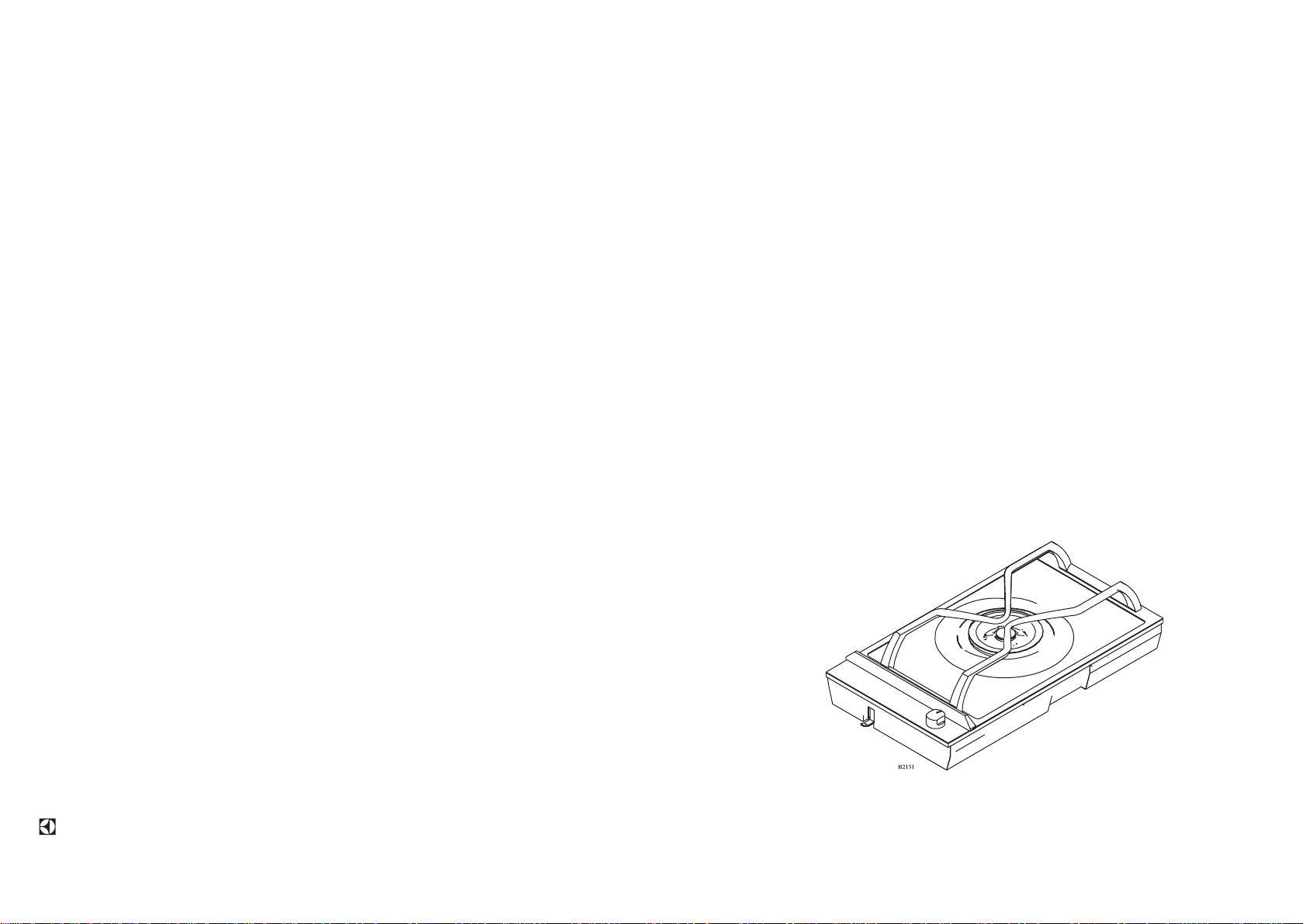
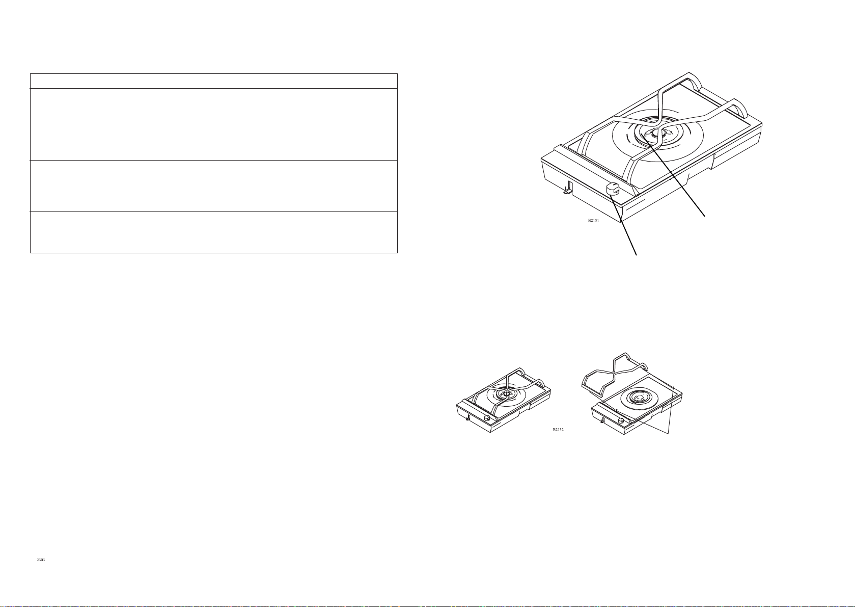
Description of the product
Sympton:
There is no spark when lighting the
gas?
When the operating knob is released
the gas ring goes out again?
The gas ring burns very unevenly??
Solution
Check appliance is connected to the
electricity supply. Check the fuse and
replace if necessery.
The operating knob has not been
depressed long enough, or has not
been depressed sufficiently.
Ensure the cover has been replaced
correctly, e.g. after cleaning.
Burner
Knob
Placement of grid
16
Guide knop for grid
5
Page 6

Operatings instructions
Technical data
The operating knob has a ring showing
the scale of markings.
Off.
Max. flame
and ignition position
Min. flame
Type of gas
Natural, G-20 - 20mbar
Category and pressures
II
Max. nominal load Q, HS:
Wok burner = 3,9 kW x 1
Total= 3,9 kW
FSD
The unit features fully-secured gas taps
(thermo-fuse).
HS = Gross calorific value
Q = Nominal load
Voltage= 220-240 V AC
Ignition transformer= 50 HZ - 0,6 VA
CE 048 BO- 0039
20 - 28/37 mbar
2H3+
240 V
1N + PE
N L1
The Dropinett must be connected via
an external switch with a contact
gap of min. 3 mm (the main switch
may be used)
Cable type: 0,75 mm² HO5VV-F
Radio-noise reduction
This unit observes the current EEC-directive
on radio noise reduction.
This gas appliance is -approved and marked in accordance with the gas appliance
Directive (90/396/CEE), the low voltage
directive (73/23/CEE) and the EMC directive
(89/336/CEE incl. the agreed directive
changes.
6
15
Page 7
Gas installation
In accordance with local
requirements for domestic gas
cooking appliances.
Gas installation must only be
carried out by an authorised person.
For gas types see technical data.
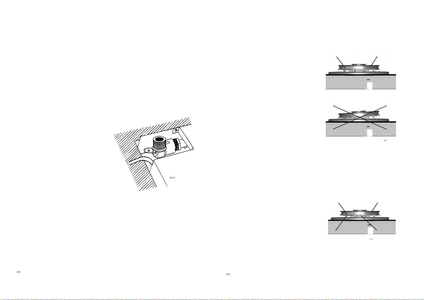
Gas connection
The gas intake is situated at the
lower rear of the appliance. The
intake has a ½" conical pipe thread
(see fig 1) If the appliance is to be
connected to a gas cylinder,
conversion with the optional
modification kit will be necessary.
Pressure test
The unit should be pressure-tested
at Max. 150 mbar.
Burner cover/burner ring
Together with the burner ring the burner
cover forms a space where the final
mixture of gas and air takes place in
Burner ring Burner cover
Correct
order to make the gas burn correctly.
Please note: It is consequently very
important that the burner cover/ring is
placed correctly on the burner. The
burner ring has been provided with
Wron g
holes for the ignition electrode, and the
thermo sensor.
If the burner cover/ring are wrongly
placed the burner will operate
incorrectly, and the burners may be
damaged within at short space of time.
Ignition electrode (A)
The burner has been provided with an
ignition electrode. As long as the
operating knob is depressed, the
automatic ignition will ensure that a
spark is emitted between the ignition
electrode and the burner cover.
Burner Main nozzle
Burner ring Burner cap
14
Thermo Sensor (B)
The hob unit features fully-secured gas
taps (thermo-fuse)
In case the flame goes out, the thermo
sensor automatically prevents gas
admission after a few seconds (max. 90
seconds).
Note: Gas admission is always allowed
while the operation button is pressed See start-up procedure
Ignition electrode (A) T hermo Sensor (B)
7
Page 8

The wok-unit has a special pan support
which enables use of a wok pot with
curved bottom.
When using cooking utensils with a
flat bottom the diameter of the utensils
must not be less than 26 cm.
It is not necessary to attach the
reinforcement beam to the work top
surface, as it is held in place by a
specially designed moulding, which is
incorporated in the hob units flanges.
The units externally measured
length
145 mm:
Cooker hood
290 mm:
Two-zone ceramic-top electric hob
Two-burner gas hob
Grill
Fryer
Wok
580 mm:
Four-zone ceramic-top electric hob
Four-burner gas hob
725 mm:
Four-zone ceramic-top electric hob
Installation of a single unit
When mounting a single unit, be it a
half-or full size unit, in a
worktopsurface which is thicker than
30 mm, it is necessary to make a
special notch in both sides of the cutout hole, as shown in the adjacent
drawing.
The purpose of these notches is to
create space for the electrical cables.
8
13
Page 9

Mounting
Ignitions
Caution: In order to avoid a hazard this
appliance must be installed according to
these instructions for installation
The hob unit can be mounted in any
type of kitchen with a table surface
whose thickness is between 28 mm and
40 mm.
Headroom
The distance to any shelves or tops of a
cabinet under the hob is to be at least 55
mm.
Fixing
Screw the fixing brackets out to such an
extent that they can be turned in under
the table top. Tighten the brackets on to
the table top with an ordinary
screwdriver.
Cut-out measurements
One rectangular hole is sawn out for the
hob combination chosen.
The depth of the cut-out for any unit is:
490 mm
Length of hole = sum of all units`
externally measured length, less 20 mm.
Minimum distance
to wall:
150 mm
Reinforcement
beams
MIN 55
Minimum distance to
wall (non flammable
material): 50 mm
1. Depress and turn the control knob
for the burner, the left to Max. flame
2. The ignition electrode will emit
sparks, and when the mixture of gas
and air is correct, the burner will be
ignited. Is not possible to connect
the unit to mains, a match may be
used to ignite the burner
3. After starting the burner, press the
control knob for approx. 10
seconds to activate the automatic
thermo couple.
4. Important Ignition position is at
Max flame
Mounting of Reinforcement
Beams
A reinforcement Beam, with supporting
flanges at each end, is included with
each two-burner unit. For unit
combinations, a reinforcement beam
must be used between each unit.
12
9
Page 10
Cleaning and maintenance of
For reasons of hygiene and
safety, the cooking burner
must be kept clean.
Grease stains and spilled
food generate smoke when
heated, and can even cause
fire.
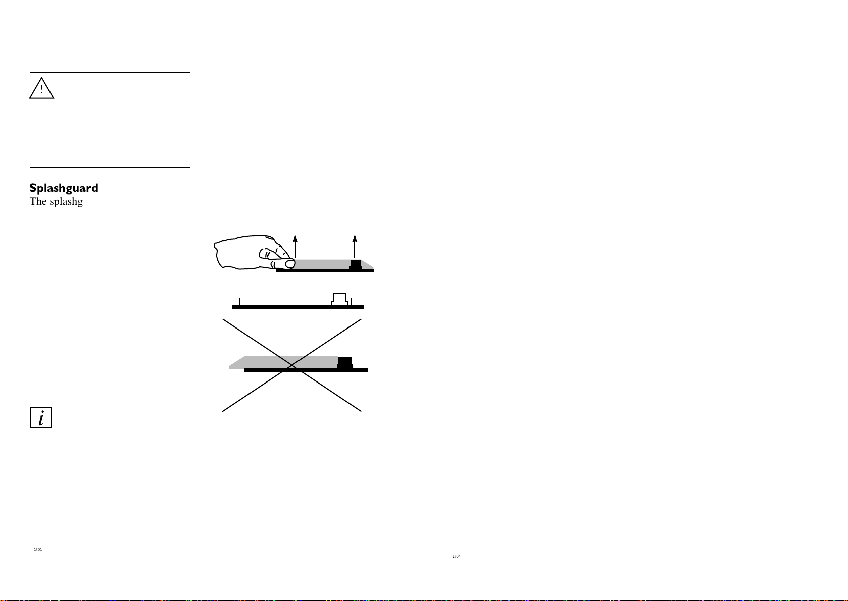
The splashguard can be removed to
make it easier to clean the surface.
What to do:
1. Hold the splashguard as shown
in the diagram.
2. Lift the splashguard straight up
3. Clean the top surface as
described in “cleaning the steel
surface”.
Be aware of the two retaining
pegs, which are sharp.
4. Replace the splashguard in
position ENSURE that it is
fitted the correct way round.
Stainless steel surfaces
Perform daily cleaning with a slightly
damp cloth. For more severe soiling,
use a liquid cream. Always clean the
steel in the direction of the steel finish.
To ensure that the steel retains its
shine, it is recommended that you use a
polishing agent for stainless steel on a
regular basis. Always polish in the
direction of the steel finish (crosswise).
Never use steel wool, metal sponges or
other abrasive cleaning agents.
Cleaning of gas burner
Clean the control panel and knobs plus
the pan grid, as well as burner caps and
rings, with ordinary cleansing agents.
Never use scouring powder, Brillo
pads, metal pads or other scouring
agents on enamelled or painted
surfaces!
Never use hard or sharp
implements to lift off the
splashguard.
Do not wash the splashguard
in a dishwasher.
The hob must not be used
with the splashguard off.
10
Care must be taken to avoid
boil-over
If water accidentally gets into the edge
of the burner head (boil-over) the water
must be removed with a lint-free cloth
before the burner is turned on again.
Likewise, caps and grids must be
thoroughly wiped off before the gas
ring is used again so that the boil-over
does not permanently scar the enamel
or paint.
11
 Loading...