

Electrolux E36GF76GPS, 318201761, E36GF75GPS, E30GF74GPS User Manual
E30GF74GPS E36GF75GPS E36GF76GPS
318201761
2
Finding Information
READ AND SAVE THESE INSTRUCTIONS
NONO
TETE
NO
TE
NONO
TETE
Installer: Leave instructions with owner. Owner: Read your range Use & Care guide. It
contains important safety information for operating this appliance. It also has many
suggestions for getting the best results from your appliance.
Read all instructions before installing the range.
For your safety, please read and observe all safety instructions. This
guide will help you anticipate all installations connections.
QUESTIONS
For toll-free telephone support in the U.S. and Canada:
1-877- 4ELECTROLUX (1-877-435-3287)
For online support and Internet product information:
www.electroluxusa.com
©2007 Electrolux Home Products, Inc.
Post Office Box 212378, Augusta, Georgia 30917, US
All rights reserved. Printed in the USA

Finding Information
TABLE OF CONTENTS
Please Read And Save This Guide .................... 2
Questions .......................................................... 2
Table Of Contents ............................................. 3
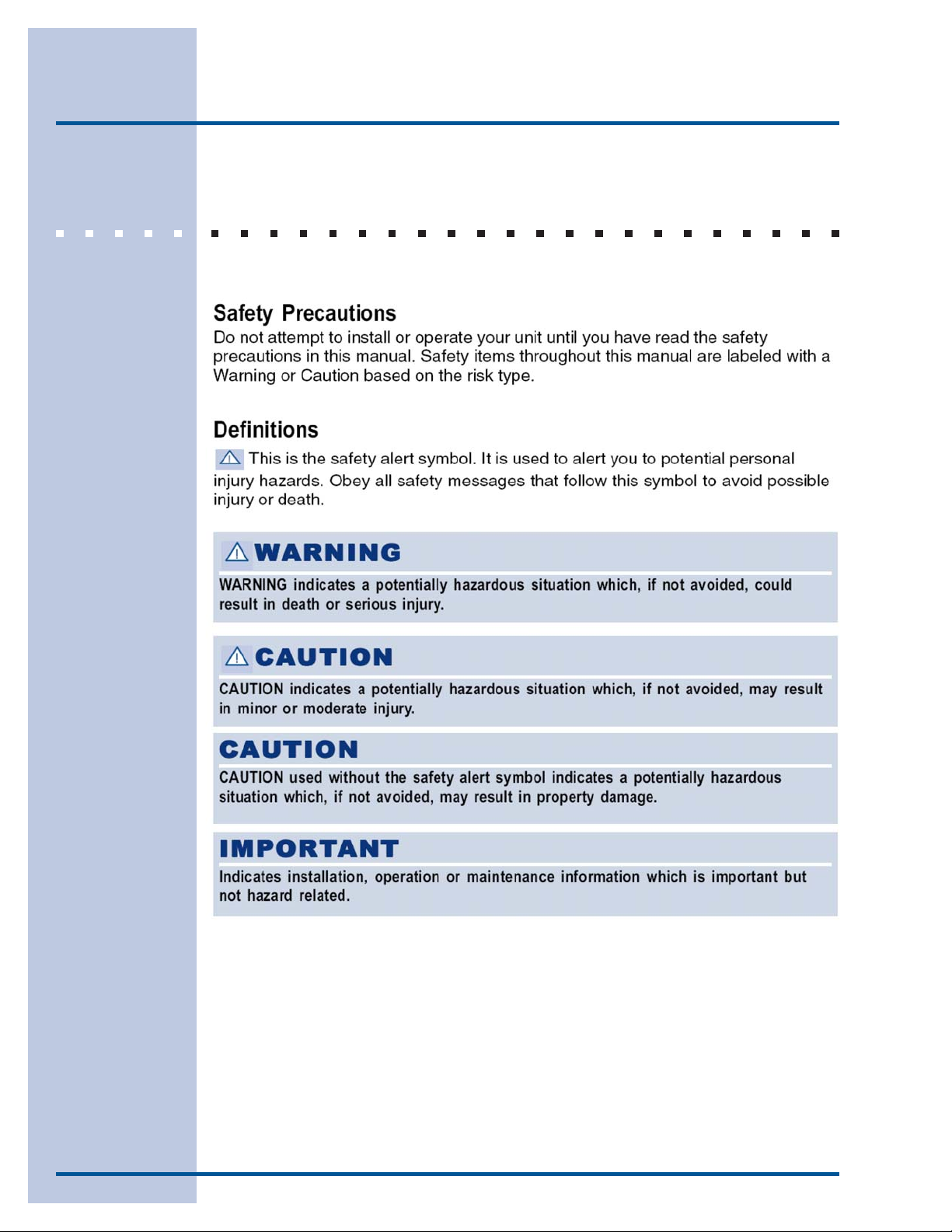
Safety ..................................................................... 4
Important Safety Instructions ............................... 4
Definitions ........................................................... 4
Safety Precautions ........................................... 5
Preparing for Installation ................................... 7
3
Verifying Package Contents ................................ 7
Gas/Electric Requirement Table............................... 7
Electrical Power Supply Requirements .................. 8
Gas/Electric Connection Rough-In ..................... 9
Cabinet/Countertop Preparation .......................... 10
General Dimensions ........................................ 11
Wood/Composite Overlay Installation...................... 13
Installing Anti-Tip Bracket ...................................... 14
Installing the 36” Range Optional Backguard......... 15
Removing Oven Door.......................................... 16
Re-Installing Oven Door.................................. 16
Grounding..................................................... 17
Connect Range To Gas Supply.........................17
Installing Range...............................................18
Verifying the Operation ...................................... 19
To Insure Proper and Safe Operation..................... 20
Converting from Natural Gas T o LP Gas................. 21
4
Safety
IMPORTANT SAFETY INSTRUCTIONS

SAFETY PRECAUTIONS
Safety
5
6
Safety
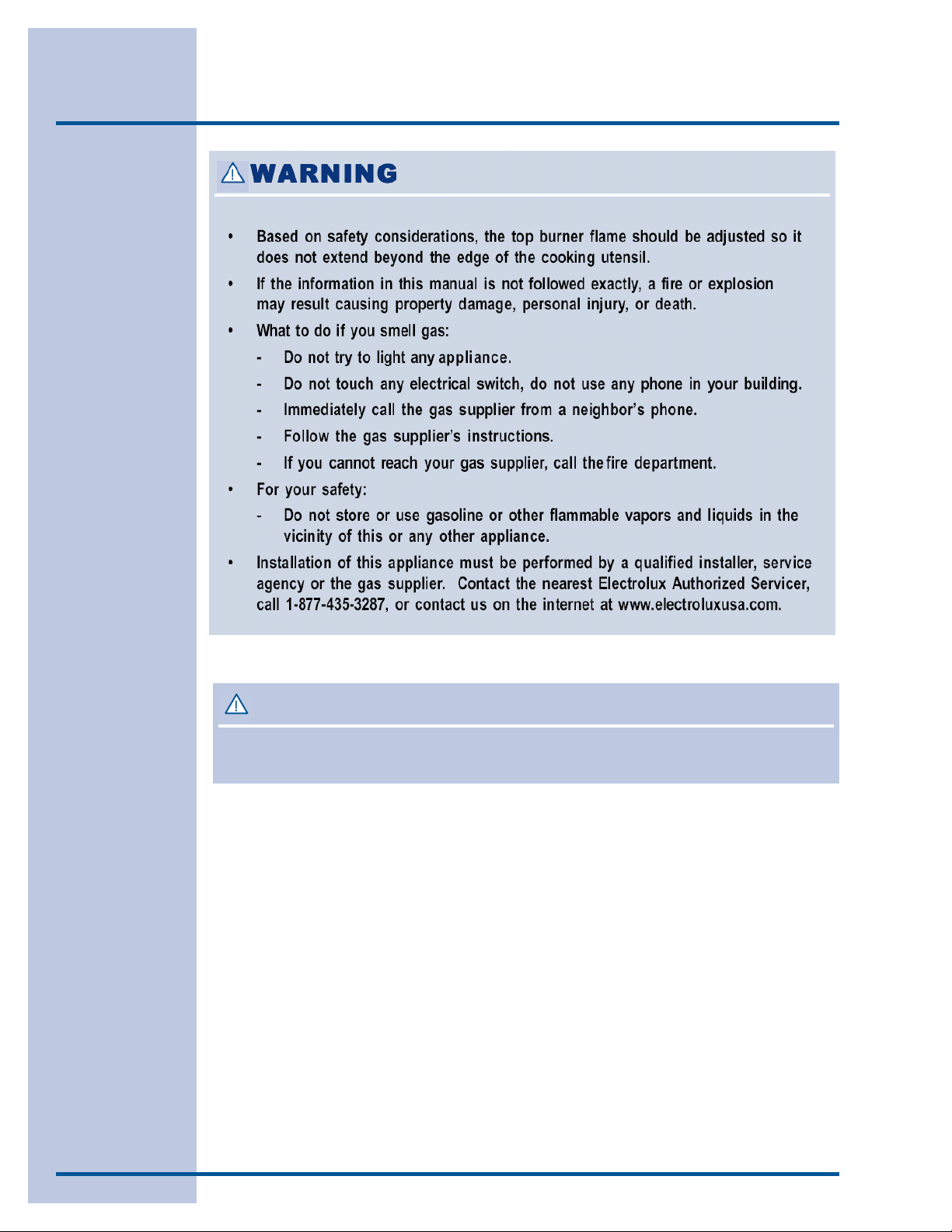
WARNINGWARNING
WARNING
WARNINGWARNING
Never use this appliance as a space heater to heat or warm a room. Doing so may result in carbon
monoxide poisoning and overheating of the oven.
Preparing for Installation
VERIFY PACKAGE CONTENTS
• Literature Pack • Griddle (some models)
• Anti-Tip Bracket • Simmer Plate
• Burner Grate Pack • Broiler Pan/Insert
• Burner Rings • Stainless Steel Cleaner
• LP Conversion Kit • Wok Ring
• Burner Caps • Oven Racks
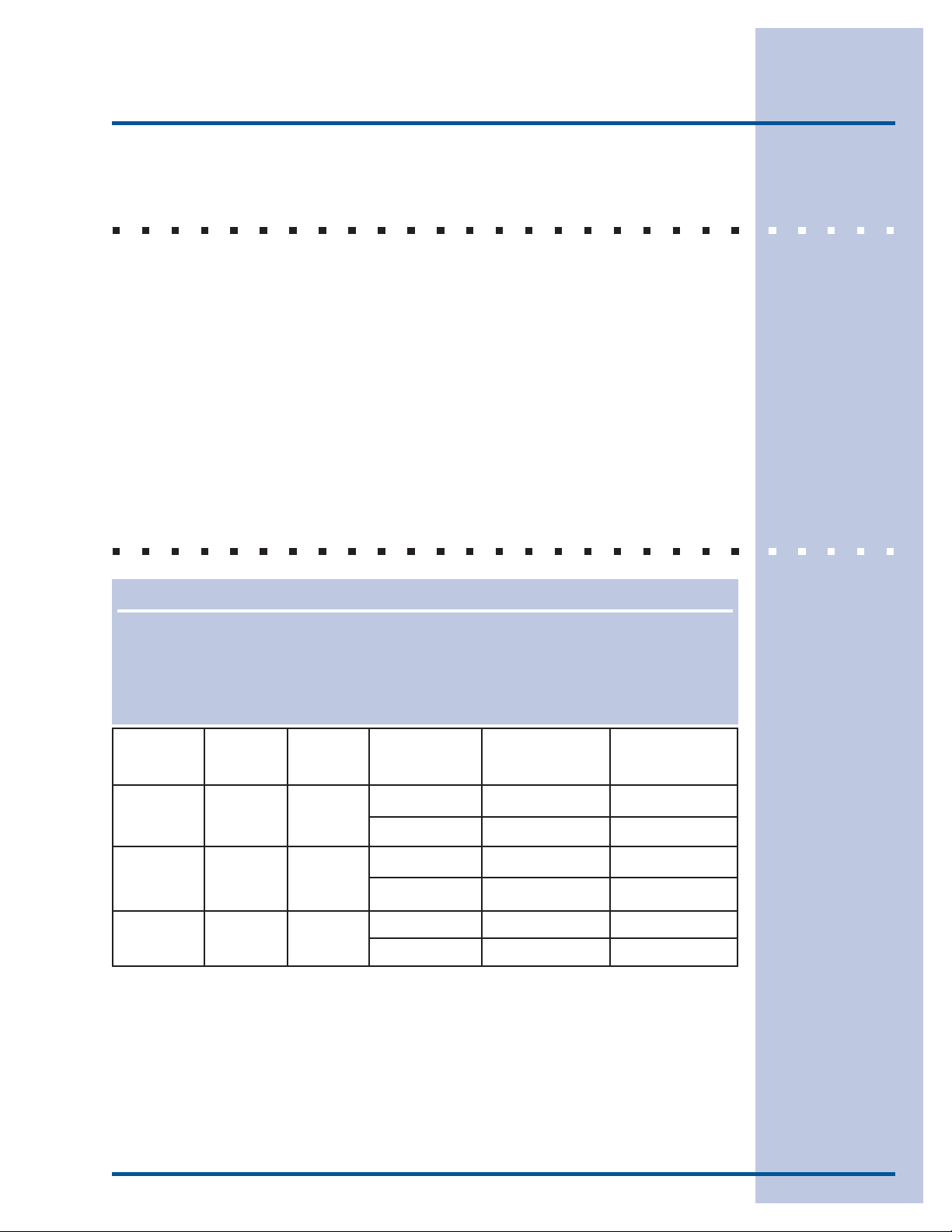
GAS AND ELECTRIC REQUIREMENT TABLE
7
NONO
TETE
NO
TE
NONO
TETE
This range is shipped from the factory pre-set for use with natural gas. For LP conversion see the
accompanying LP Conversion Kit. The electrical information in the table is also located on the
serial number label on the range.
Model No.
Electrical
Circuit
Total
Connected
Gas Type
Manifold Pressure Minimum Gas
Supply
Water Column Inches Water Column Inches
E30GF74GPS
E36GF75GPS
E36GF76GPS
120 V,
60Hz,
120 V,
60Hz,
120 V,
60Hz,
5A
8A
5A
Natural
Liquid Propane
Natural
Liquid Propane
Natural
Liquid Propane
5"
10"
5"
10"
5"
10"
6"
11"
6"
11"
6"
11"
8
Preparing for Installation
ELECTRICAL POWER SUPPLY REQUIREMENTS
It is the owner’s responsibility to ensure that the electrical connection
of this appliance is performed by a qualified electrician. The electrical
installation, including minimum supply wire size and grounding, must be
in accordance with the National Electric Code ANSI/NFPA 70-1993*
(or latest revision) and local codes and ordinances. In Canada,
electrical grounding must be in accordance with the current CSA C22.1
Canadian Electrical Code Part 1 and/or local codes.
*A copy of the standard must be obtained from:
National Fire Protection Association
1 Batterymarch Park
Quincy, Massachusetts 02269-9101
The correct voltage, frequency, and amperage must be supplied to the
appliance from a separate, grounded, circuit that is protected by a
properly sized circuit breaker or time delay fuse.
WARNINGWARNING
WARNING
WARNINGWARNING
If the gas or electric service provided does not meet the product specifications, do not
proceed with the installation. Call the selling dealer, the gas supplier, or a licensed
electrician.
NONO
TESTES
NO
TES
NONO
TESTES
The power supply must be properly grounded. Improper grounding will result in
continuous sparking of the electrodes, even after flame ignition.
If there is any doubt as to whether the power supply is properly polarized or grounded,
have it checked by a qualified electrician.
Use 120V, 60Hz, and properly grounded branch circuit protected by a 15-amp or 20-amp
circuit breaker or time delay fuse.
Preparing for Installation
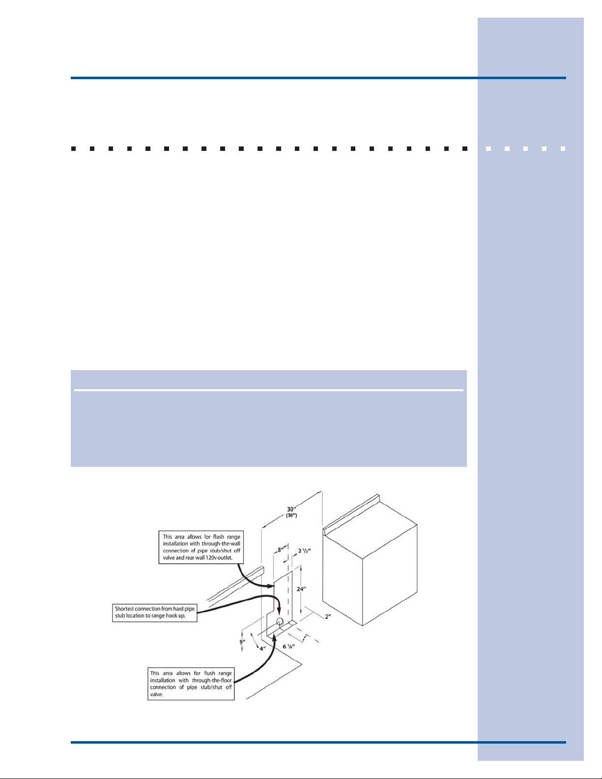
GAS AND ELECTRICAL ROUGH-IN
Locations
A manual shut valve must be installed in the gas piping, external to the
appliance, for the purpose of turning on or shutting off gas to the
appliance. Place the location of the range and the gas supply to allow
access to the valve when the unit is installed. Access to the remote
circuit breaker panel/fuse box, with the range in place, must also be
allowed for in the installation. Any openings in the wall behind the
appliance and in the floor under the appliance must be sealed. Both the
gas supply piping and shut-off valve, and the electrical junction box/
receptacle must be located so they do not interfere with the range when
it is installed. In addition, the junction box must be located so the range
can be removed for service when the conduit supplied with the unit is
attached to the junction box. Do not lengthen the conduit or wiring
provided with the range.
9
NONO
TESTES
NO
TES
NONO
TESTES
The areas shown in the illustrations, denote the location of the gas stub and the
electrical junction box/receptacle. These are suggested locations. For replacement
purposes, the location of the existing utilities may be utilized provided that they do not
interfere with the sides or rear of the range. If installing the gas valve behind the range,
verify that local building codes will permit this.
Figure 1
Center Line
 Loading...