

Page 1

(/(&752/8;+20(352'8&761257+$0(5,&$
SERVICE MANUAL
24" BUIL T -IN DISHWASHERS
2001 MECHANICAL MODELS
PRECISION WASH SYSTEM
5995355186
:KLWH : HVWLQJKRXVH
June 2001
Page 2

TABLE OF CONTENTS
SAFE SERVICING PRACTICES ................................................................................ 3
WHAT'S NEW ............................................................................................................. 4
MODEL TECHNICAL SPECIFICATIONS
Frigidaire .................................................................................................................................................. 5 - 8
Universal - Multiflex ................................................................................................................................... 9
Amana ..................................................................................................................................................... 10 - 11
Crown ...................................................................................................................................................... 11
Gibson ..................................................................................................................................................... 12
CONSTRUCTION AND OPERATION
Water Distribution System ...................................................................................................................... 13
Water Distribution Components ............................................................................................................... 13
Wash Pump ...................................................................................................................................... 13
Upper Spray Arm .............................................................................................................................. 14
Lower Spray Arm .............................................................................................................................. 14
Lower Spray Arm with Collapsible Tower ..........................................................................................14
Filter ................................................................................................................................................. 14
Polyprolene Filter .............................................................................................................................. 14
Stainless Steel Filter ........................................................................................................................ 14
Drain Pump ...................................................................................................................................... 15
Drying System ........................................................................................................................................ 15
Static Dry System ............................................................................................................................15
Active Vent System ......................................................................................................................... 15
Power Vent System..........................................................................................................................15
Drying System Components ................................................................................................................... 16
Lower Vent Housing .......................................................................................................................... 16
Vent Valve........................................................................................................................................ 16
Vent Actuator ................................................................................................................................... 16
Blower .............................................................................................................................................. 16
Upper Vent Housing .......................................................................................................................... 16
Dispensing System ................................................................................................................................. 17
Detergent & Rinse Aid Dispenser...................................................................................................... 17
Dispenser Operation ......................................................................................................................... 17
Door Latch Assembly.............................................................................................................................. 17
Selector Switch and Thermostats ........................................................................................................... 18
Heated Dry ....................................................................................................................................... 18
Hi-Temp Wash .................................................................................................................................. 18
Hi-Temp Rinse .................................................................................................................................. 18
High Limit Thermostat ...................................................................................................................... 18
Dishwasher Leveling ............................................................................................................................... 19
DISASSEMBLY
Safety Precautions ................................................................................................................................. 20
Control Panel .......................................................................................................................................... 20
Timer ...................................................................................................................................................... 20
Disassembly Tip ...............................................................................................................................20
Selector Switch ....................................................................................................................................... 20
Door Panels (All Models)......................................................................................................................... 20
Page 1
Page 3

TABLE OF CONTENTS
Door Vent Assembly ............................................................................................................................... 20
Vent Valve .............................................................................................................................................. 21
Vent Actuactor ........................................................................................................................................ 21
Vent Blower .................................................................................................................... ........................21
Door Latch Assembly.............................................................................................................................. 21
Detergent / Rinse Aid Dispenser ............................................................................................................. 21
Inner Door Panel ..................................................................................................................................... 21
Door Seal ................................................................................................................................................ 21
Upper Rack ............................................................................................................................................. 22
Upper Water Tube ............................................................................................................... ....................22
Upper Spray Arm .................................................................................................................................... 22
Water Distributor ..................................................................................................................................... 22
Kick Plate ............................................................................................................................................... 22
Heating Element ................................................................................................................ ..................... 22
Float Switch and Bracket ........................................................................................................................ 23
Water Valve ............................................................................................................................................ 23
Drain Pump ............................................................................................................................................. 23
Lower Spray Arm .................................................................................................................................... 23
Glass Trap .............................................................................................................................................. 23
Lower Spray Arm Support ....................................................................................................................... 23
Filter ....................................................................................................................................................... 24
Pump and Motor Assembly ..................................................................................................................... 24
Motor Mounting Bracket .......................................................................................................................... 24
Motor and Impeller .................................................................................................................................. 24
Thermostats............................................................................................................................................25
High Limit Thermostat ............................................................................................................................. 25
Indicator Lamps ...................................................................................................................................... 25
TROUBLESHOOTING
Troubleshooting Tips ........................................................................................................................ 26 - 27
APPENDIX A - Diagrams - Exploded Views .............................................................A - 1
APPENDIX B - Service Data Sheets (Wiring Diagrams & Timer Charts)................B - 1
Page 2
Page 4

SAFE SERVICING PRACTICES - ALL APPLIANCES
To avoid personal injury and/or property damage, it is important that Safe
Servicing Practices be observed. The following are some limited examples of
safe practices:
1. DO NOT attempt a product repair if you have any doubts as to your ability to
complete it in a safe and satisfactory manner.
2. Before servicing or moving an appliance:
Remove the power cord from the electrical outlet, trip the circuit breaker to
the OFF position, or remove the fuse.
Turn off the gas supply.
Turn off the water supply.
3. Never interfere with the proper operation of any safety device.
4. USE ONLY REPLACEMENT PARTS CATALOGED FOR THIS APPLIANCE.
SUBSTITUTIONS MAY DEFEAT COMPLIANCE WITH SAFETY
STANDARDS SET FOR HOME APPLIANCES.
5. GROUNDING: The standard color coding for safety ground wires is GREEN,
or GREEN with YELLOW STRIPES. Ground leads are not to be used as current
carrying conductors. It is EXTREMELY important that the service technician
reestablish all safety grounds prior to completion of service. Failure to do so
will create a hazard.
6. Prior to returning the product to service, ensure that:
All electrical connections are correct and secure
All electrical leads are properly dressed and secured away from sharp
edges, high-temperature components, and moving parts
All non-insulated electrical terminals, connectors, heaters, etc. are
adequately spaced away from all metal parts and panels
All safety grounds (both internal and external) are correctly and securely
connected
All panels are properly and securely reassembled
ATTENTION!!!
This service manual is intended for use by persons having electrical and mechnical
training and a level of knowledge of these subjects generally considered acceptable in the
appliance repair trade. Electrolux Home Products cannot be responsible, nor assume any
liability, for injury or damage of any kind arising from the use of this manual.
© 2001 White Consolidated Industries
Page 3
Page 5

WHAT'S NEW
Ö COLLAPSIBLE TOWER - Single wash arm on low end models with collaspsible tower that is molded into the
spray arm. This tower retracts completely into the lower arm giving added area in the lower rack.
Ö VENT COVER- The vent cover has the gasket molded into the cover to prevent water leaks.
Ö PUMP AND MOTOR ASSEMBLY - The wash pump and motor are in one piece and is not repairable. The new
design motor does not have nor need a seal to prevent water leaks. In the end of this motor is a small circuit
board that is designed to make sure that the motor will always start in the proper direction. This new motor is
mounted with a new mounting bracket that only requires two screws.
Ö SANITIZE RINSE - On the higher end models, a sanitize rinse setting has been added and the rinse temperature
will reach 150°F.
Page 4
Page 6
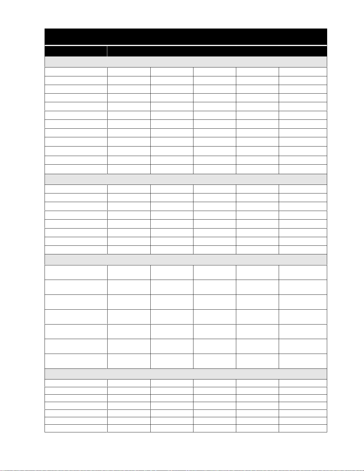
FRIGIDAIRE
MODEL FDB125RH*2 FDB345LF*2 FDB421RF*6 FDB421RF*7 FDB435RFR*6
ELECTRICAL
Service Data Sheet 154395901 154400501 154370901 154405901 154385401
Voltage 120 VAC 120 VAC 120 VAC 120 VAC 120 VAC
Cycles 60 Hertz 60 Hertz 60 Hertz 60 Hertz 60 Hertz
Circuit Rating (Amps) 15 / 20 15 / 20 15 / 20 15 / 20 15 / 20
Motor (HP) 1/12
th
Motor (Amps) 1.1 1.1 1.1 1.1 1.1
Heater (Watts) 900 900 900 900 900
Total Amps 10 10 10 10 10
Temp Assure
Temp Boost
117°F
127°F (53
Sanitize N/A N/A N/A N/A
Hi-Limit Thermostat
200°F (93
COMPONENT RESISTANCE (ohms)
Timer Motor 2357 2357 7700 7700 2357
Heating Element 13.5 9.28 9.28 9.28 9.28
Pump Motor
Vent Actuator N/A 1893 1893 1893 1893
Dispenser 1928 1928 1928 1928 1928
Drain Motor 28 28 28 28 28
Water Valve Solenoid 699 699 699 699 699
Blower N/A N/A N/A N/A N/A
1/12
th
± 5°F
th
1/12
1/12
N/A N/A
th
°C) 122°F (50°C) 122°F (50°C) 127°F (53°C)
°C) 200°F (93°C) 200°F (93°C) 200°F (93°C)
1/12
117°F
th
± 5°F
WATER SUPPLY
Minimum Incoming
Water Temperature
Pressure
(min/max - psi)
Connection
(NPT)
Normal Cycle Water
Consumption (gal.)
Water valve Flow Rate
(GPM)
Water Recirculation
Rate (GPM)
Water Fill Time
(Seconds)
120°F
(49°C)
20 / 120 20 / 120 20 / 120 20 / 120 20 / 120
3/8" 3/8" 3/8" 3/8" 3/8"
7.2 6 6 6 6
12 12 12 12 12
DIAGRAMS (Located in Appendix A or B)
Service Data Sheet
Control Panel
Door
Tub
Motor & Pump
Frame
Racks
B - 9 B - 16 B - 1 B - 21 B - 7
A - 9 A - 10 * * *
A - 17 A - 18 * * *
A - 20 A - 20 * * *
A - 23 A - 24 * * *
A - 29 A - 29 * * *
A - 35 A - 32 * * *
120°F
(49°C)
120°F
(49°C)
120°F
(49°C)
.83 .83 .83 .83
87 87 87 87
120°F
(49°C)
* Information not available - Parts Catalogs not created as of this Publication date
Page 5
Page 7
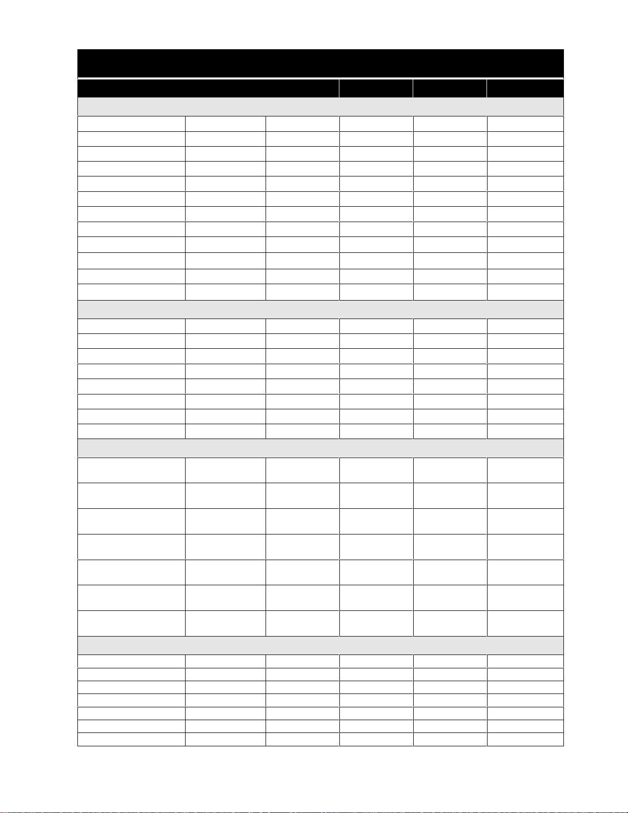
FRIGIDAIRE
MODEL FDB435RFS*4 FDB634CF*4 FDB635RF*6 FDP635RF*5 FDB641RA*0
ELECTRICAL
Service Data Sheet 154385401 154396801 154396801 154396801 154403801
Voltage 120 VAC 120 VAC 120 VAC 120 VAC 120 VAC
Cycles 60 Hertz 60 Hertz 60 Hertz 60 Hertz 60 Hertz
Circuit Rating (Amps) 15 / 20 15 / 20 15 / 20 15 / 20 15 / 20
Motor (HP) 1/12
th
Motor (Amps) 1.1 1.1 1.1 1.1 1.1
Heater (Watts) 900 900 900 900 900
Total Amps 10 10 10 10 10
Temp Assure
Temp Boost
117°F
± 5°F
127°F (53
117°F
°C) 122°F (50°C) 122°F (50°C) 122°F (50°C) 122°F (50°C)
Sanitize N/A N/A N/A N/A N/A
Hi-Limit Thermostat
200°F (93
°C) 200°F (93°C) 200°F (93°C) 200°F (93°C) 200°F (93°C)
COMPONENT RESISTANCE (ohms)
Timer Motor 2357 2357 2357 2357 7700
Heating Element 9.28 9.28 9.28 9.28 9.28
Pump Motor
Vent Actuator 1893 1893 1893 1893 N/A
Dispenser 1928 1928 1928 1928 1928
Drain Motor 28 28 28 28 28
Water Valve Solenoid 699 699 699 699 699
Blower N/A N/A N/A N/A N/A
1/12
th
± 5°F
1/12
117°F
th
± 5°F
1/12
117°F
th
± 5°F
1/12
N/A
th
WATER SUPPLY
Minimum Incoming
Water Temperature
Pressure
(min/max - psi)
Connection
(NPT)
Normal Cycle Water
Consumption (gal.)
Water valve Flow Rate
(GPM)
Water Recirculation
Rate (GPM)
Water Fill Time
(Seconds)
120°F
(49°C)
20 / 120 20 / 120 20 / 120 20 / 120 20 / 120
3/8" 3/8" 3/8" 3/8" 3/8"
66666
.83 .83 .83 .83 .83
12 12 12 12 12
87 87 87 87 87
DIAGRAMS (Located in Appendix A or B)
Service Data Sheet
Control Panel
Door
Tub
Motor & Pump
Frame
Racks
B - 7 B - 15 B - 15 B - 15 B - 20
* A - 11 A - 11 B - 11 *
* A - 18 A - 18 A - 18 *
* A - 20 A - 20 A - 19 *
* A - 24 A - 24 A - 24 *
* A - 29 A - 29 A - 25 *
* A - 32 A - 32 A - 32 *
120°F
(49°C)
120°F
(49°C)
120°F
(49°C)
120°F
(49°C)
* Information not available - Parts Catalogs not created as of this Publication date
Page 6
Page 8
FRIGIDAIRE
MODEL FDB641RJ*1 FDP641RA*0 FDB657RJ*1 FDB658RA*0
ELECTRICAL
Service Data Sheet 154403801 154403801 154396201 154396201
Voltage 120 VAC 120 VAC 120 VAC 120 VAC
Cycles 60 Hertz 60 Hertz 60 Hertz 60 Hertz
Circuit Rating (Amps) 15 / 20 15 / 20 15 / 20 15 / 20
Motor (HP) 1/12
Motor (Amps) 1.1 1.1 1.1 1.1
Heater (Watts) 900 900 900 900
Total Amps 10 10 10 10
Temp Assure N/A N/A N/A N/A
Temp Boost
Sanitize
Hi-Limit Thermostat
122°F (50°C) 122°F (50°C) 122°F (50°C) 122°F (50°C)
200°F (93
th
N/A N/A
°C) 200°F (93°C) 200°F (93°C) 200°F (93°C)
COMPONENT RESISTANCE (ohms)
Timer Motor 7700 7700 2357 2357
Heating Element 9.28 9.28 9.28 9.28
Pump Motor
Vent Actuator N/A N/A 1893 1893
Dispenser 1928 1928 1928 1928
Drain Motor 28 28 28 28
Water Valve Solenoid 699 699 699 699
Blower N/A N/A N/A N/A
1/12
th
137°F (58
th
1/12
°C) 137°F (58°C)
1/12
th
WATER SUPPLY
Minimum Incoming
Water Temperature
Pressure
(min/max - psi)
Connection
(NPT)
Normal Cycle Water
Consumption (gal.)
Water valve Flow Rate
(GPM)
Water Recirculation
Rate (GPM)
Water Fill Time
(Seconds)
DIAGRAMS
Service Data Sheet
(Located in Appendix A or B)
Control Panel
Door
Motor & Pump
Frame
Racks
Tub
120°F
(49°C)
20 / 120 20 / 120 20 / 120 20 / 120
3/8" 3/8" 3/8" 3/8"
6666
.83 .83 .83 .83
12 12 12 12
87 87 87 87
B - 20 B - 20 B - 11 B - 11
****
****
****
****
****
****
120°F
(49°C)
120°F
(49°C)
120°F
(49°C)
* Information not available - Parts Catalogs not created as of this Publication date
Page 7
Page 9

FRIGIDAIRE
(Gallery Models)
MODEL GLDB653A*0 GLDB653J*2 GLDB656J*1 GPDB698J*1 GLDB756A*0
ELECTRICAL
Service Data Sheet 154402401 154396801 154396201 154396201 154402501
Voltage 120 VAC 120 VAC 120 VAC 120 VAC 120 VAC
Cycles 60 Hertz 60 Hertz 60 Hertz 60 Hertz 60 Hertz
Circuit Rating (Amps) 15 / 20 15 / 20 15 / 20 15 / 20 15 / 20
Motor (HP) 1/12
Motor (Amps) 1.1 1.1 1.1 1.1 1.1
Heater (Watts) 900 900 900 900 900
Total Amps 10 10 10 10 10
Temp Assure 117°F ± 5°F 117°F ± 5°F N/A N/A 117°F ± 5°F
Temp Boost
Sanitize
Hi-Limit Thermostat
122°F (50
200°F (93
th
°C) 122°F (50°C) 122°F (50°C) 122°F (50°C)
N/A N/A
°C) 200°F (93°C) 200°F (93°C) 200°F (93°C) 200°F (93°C)
1/12
th
137°F (58
1/12
th
1/12
th
°C) 137°F (58°C) 137°F (58°C)
1/12
N/A
th
COMPONENT RESISTANCE (ohms)
Timer Motor 2357 2357 2357 2357 2357
Heating Element 9.28 9.28 9.28 9.28 9.28
Pump Motor N/A
Vent Actuator N/A 1893 1893 1893 1893
Dispenser 1928 1928 1928 1928 1928
Drain Motor 28 28 28 28 28
Water Valve Solenoid 699 699 699 699 699
Blower N/A N/A N/A N/A 214
WATER SUPPLY
Minimum Incoming
Water Temperature
Pressure
(min/max - psi)
Connection
(NPT)
Normal Cycle Water
Consumption (gal.)
Water valve Flow Rate
(GPM)
Water Recirculation
Rate (GPM)
Water Fill Time
(Seconds)
120°F
(49°C)
20 / 120 20 / 120 20 / 120 20 / 120 20 / 120
3/8" 3/8" 3/8" 3/8" 3/8"
6666 6
.83 .83 .83 .83 .83
12 12 12 12 12
87 87 87 87 87
DIAGRAMS (Located in Appendix A or B)
Service Data Sheet
Control Panel
Door
Tub
Motor & Pump
Frame
Racks
B - 17 B - 15 B - 11 B - 11 B - 18
* A - 11 A - 3 A - 6 *
* A - 18 A - 18 A - 17 *
* A - 21 A - 21 A - 21 *
* A - 25 A - 25 A - 25 *
* A - 30 A - 30 A - 31 *
* A - 33 A - 34 A - 35 *
120°F
(49°C)
120°F
(49°C)
120°F
(49°C)
120°F
(49°C)
* Information not available - Parts Catalogs not created as of this Publication date
Page 8
Page 10

UNIVERSAL - MULTIFLEX
MODEL MDB12 2RF*2 MDB124BA*0 MDB124BJ*1 MDB124BH*1 MDB125RH *2
ELECTRICAL
Service Data Sheet 154396001 154407901 154396001 154396001 154395901
Voltage 120 VAC 120 VAC 120 VAC 120 VAC 120 VAC
Cycles 60 Hertz 60 Hertz 60 Hertz 60 Hertz 60 Hertz
Circuit Rating (Amps) 15 / 20 15 / 20 15 / 20 15 / 20 15 / 20
Motor (HP) 1/12
th
Motor (Amps) 1.1 1.1 1.1 1.1 1.1
Heater (Watts) 900 900 900 900 900
Total Amps 10 10 10 10 10
Temp Assure N/A N/A N/A N/A N/A
Temp Boost
127°F (53
°C) 127°F (53°C) 127°F (53°C) 127°F (53°C)
Sanitize N/A N/A N/A N/A N/A
Hi-Limit Thermostat
200°F (93
°C) 200°F (93°C) 200°F (93°C) 200°F (93°C) 200°F (93°C)
COMPONENT RESISTANCE (ohms)
Timer Motor 7700 7700 7700 7700 2357
Heating Element 9.28 9.28 9.28 9.28 9.28
Pump Motor N/A N/A N/A N/A N/A
Vent Actuator 1893 1893 1893 1893 N/A
Dispenser 1928 1928 1928 1928 1928
Drain Motor 28 28 28 28 28
Water Valve Solenoid 699 699 699 699 699
Blower N/A N/A N/A N/A N/A
1/12
th
1/12
th
1/12
th
1/12
th
N/A
WATER SUPPLY
Minimum Incoming
Water Temperature
Pressure
(min/max - psi)
Connection
(NPT)
Normal Cycle Water
Consumption (gal.)
Water valve Flow Rate
(GPM)
Water Recirculation
Rate (GPM)
Water Fill Time
(Seconds)
120°F
(49°C)
20 / 120 20 / 120 20 / 120 20 / 120 20 / 120
3/8" 3/8" 3/8" 3/8" 3/8"
66667.2
.83 .83 .83 .83 .83
12 12 12 12 12
87 87 87 87 87
DIAGRAMS (Located in Appendix A or B)
Service Data Sheet
Control Panel
Door
Tub
Motor & Pump
Frame
Racks
B - 10 B - 22 B - 10 B - 10 B - 9
A - 15 * A - 15 A - 15 A - 9
A - 19 * A - 18 A - 18 A - 18
A - 21 * A - 21 A - 21 A - 21
A - 25 * A - 25 A - 25 A - 24
A - 28 * A - 28 A - 28 A - 30
A - 32 * A - 32 A - 32 A - 37
120°F
(49°C)
120°F
(49°C)
120°F
(49°C)
120°F
(49°C)
* Information not available - Parts Catalogs not created as of this Publication date
Page 9
Page 11

AMANA
MODEL ADW350RA*0 ADW350RA*1 ADW550RA*0 ADW5 50RA*1 ADW650RA *0
ELECTRICAL
Service Data Sheet 154382801 154396301 154382901 154396401 154383001
Voltage 120 VAC 120 VAC 120 VAC 120 VAC 120 VAC
Cycles 60 Hertz 60 Hertz 60 Hertz 60 Hertz 60 Hertz
Circuit Rating (Amps) 15 / 20 15 / 20 15 / 20 15 / 20 15 / 20
Motor (HP) 1/12
Motor (Amps) 3.4 1.1 3.4 1.1 3.4
Heater (Watts) 900 900 900 900 900
Total Amps 11 10 11 10 11
Temp Assure N/A N/A N/A N/A N/A
Temp Boost
Sanitize
Hi-Limit Thermostat
127°F (53
200°F (93
th
°C)
N/A N/A
127°F (53
°C) 200°F (93°C) 200°F (93°C) 200°F (93°C) 200°F (93°C)
COMPONENT RESISTANCE (ohms)
Timer Motor 7700 7700 2357 2357 2357
Heating Element 9.28 9.28 9.28 9.28 9.28
Pump Motor 4.3 N/A 4.3 N/A 4.3
Vent Actuator 1893 1893 1893 1893 1893
Dispenser 1928 1928 1928 1928 1928
Drain Motor 28 28 28 28 28
Water Valve Solenoid 699 699 699 699 699
Blower N/A N/A N/A N/A N/A
WATER SUPPLY
Minimum Incoming
Water Temperature
Pressure
(min/max - psi)
Connection
(NPT)
Normal Cycle Water
Consumption (gal.)
Water valve Flow Rate
(GPM)
Water Recirculation
Rate (GPM)
Water Fill Time
(Seconds)
DIAGRAMS
Service Data Sheet
(Located in Appendix A or B)
Control Panel
Door
Tub
Motor & Pump
Frame
Racks
120°F
(49°C)
20 / 120 20 / 120 20 / 120 20 / 120 20 / 120
3/8" 3/8" 3/8" 3/8" 3/8"
66666
.83 .83 .83 .83 .83
12 12 12 12 12
87 87 87 87 87
B - 4 B - 13 B - 5 B - 14 B - 6
A - 5 A - 12 A - 7 A - 13 A - 7
A - 16 A - 18 A - 16 A - 18 A - 16
A - 21 A - 21 A - 21 A - 21 A - 21
A - 22 A - 25 A - 22 A - 25 A - 22
A - 29 A - 28 A - 29 A - 31 A - 29
A - 32 A - 32 A - 33 A - 33 A - 34
1/12
120°F
(49°C)
th
°C)
1/12
117°F ± 5
127°F (53
120°F
(49°C)
th
°F
117°F ± 5
1/12
th
°F
122°F ± 5
1/12
th
°C) 127°F (53°C) 137°F (58°C)
120°F
(49°C)
120°F
(49°C)
°F
* Information not available - Parts Catalogs not created as of this Publication date
Page 10
Page 12
AMANA CROWN
MODEL ADW650RA*1 ADW650RA*2 F71C12PH*1 F71C24RJ*1
ELECTRICAL
Service Data Sheet 154382801 154396301 154395901 154403001
Voltage 120 VAC 120 VAC 120 VAC 120 VAC
Cycles 60 Hertz 60 Hertz 60 Hertz 60 Hertz
Circuit Rating (Amps) 15 / 20 15 / 20 15 / 20 15 / 20
Motor (HP) 1/12
Motor (Amps) 3.4 1.1 1.1 31.1
Heater (Watts) 900 900 900 900
Total Amps 11 10 10 10
Temp Assure N/A N/A N/A N/A
Temp Boost
Sanitize
Hi-Limit Thermostat
122°F
137°F (58
200°F (93
th
± 5°F 122°F ± 5°F
°C) 137°F (58°C)
°C) 200°F (93°C) 200°F (93°C) 200°F (93°C)
COMPONENT RESISTANCE (ohms)
Timer Motor 2357 2357 2357 7700
Heating Element 9.28 9.28 13.5 13.5
Pump Motor 4.3 N/A N/A N/A
Vent Actuator 1893 1893 N/A
Dispenser 1928 1928 1928 1928
Drain Motor 28 28 28 28
Water Valve Solenoid 699 699 699 699
Blower N/A N/A N/A N/A
1/12
th
th
1/12
N/A
N/A N/A
1/12
122°F (50
th
°C)
WATER SUPPLY
Minimum Incoming
Water Temperature
Pressure
(min/max - psi)
Connection
(NPT)
Normal Cycle Water
Consumption (gal.)
Water valve Flow Rate
(GPM)
Water Recirculation
Rate (GPM)
Water Fill Time
(Seconds)
120°F
(49°C)
20 / 120 20 / 120 20 / 120 20 / 120
3/8" 3/8" 3/8" 3/8"
66 7.2 6
.83 .83 .83 .83
12 12 12 12
87 87
DIAGRAMS (Located in Appendix A or B)
Service Data Sheet
Control Panel
Door
Tub
Motor & Pump
Frame
Racks
B - 4 B - 12 B - 9 B - 19
A - 7 A - 13 * *
A - 13 A - 18 * *
A - 21 A - 21 * *
A - 25 A - 22 * *
A - 29 A - 31 * *
A - 34 A - 34
120°F
(49°C)
120°F
(49°C)
87 87
**
120°F
(49°C)
* Information not available - Parts Catalogs not created as of this Publication date
Page 11
Page 13

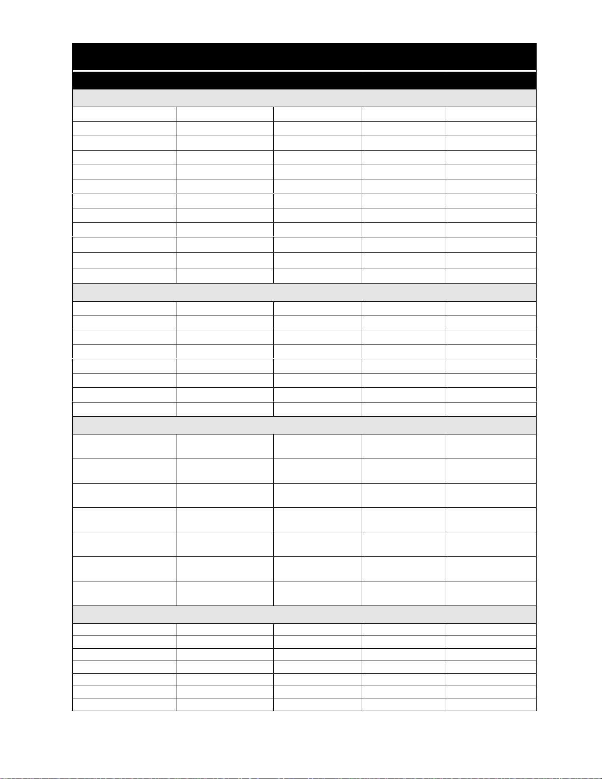
GIBSON
MODEL G DP635RH*2 GDB742RJ*0 GDB742RJ*1 GDB755RJ*0 GDB755RJ*1
ELECTRICAL
Service Data Sheet 154396801 154374101 154403001 154374001 154383001
Voltage 120 VAC 120 VAC 120 VAC 120 VAC 120 VAC
Cycles 60 Hertz 60 Hertz 60 Hertz 60 Hertz 60 Hertz
Circuit Rating (Amps) 15 / 20 15 / 20 15 / 20 15 / 20 15 / 20
Motor (HP) 1/12
Motor (Amps) 1.1 1.1 1.1 3.4 1.1
Heater (Watts) 900 900 900 900 900
Total Amps 10 10 10 11 10
Temp Assure
Temp Boost
Sanitize
Hi-Limit Thermostat
117°F
122°F (50
200°F (93
th
± 5°F
°C)
N/A N/A N/A
122°F (50
°C) 200°F (93°C) 200°F (93°C) 200°F (93°C) 200°F (93°C)
COMPONENT RESISTANCE (oh ms)
Timer Motor 2357 7700 7700 2357 2357
Heating Element 9.28 9.28 9.28 9.28 9.28
Pump Motor N/A N/A N/A 4.3 N/A
Vent Actuator 1893 1893 1893 1893 1893
Dispenser 1928 1928 1928 1928 1928
Drain Motor 28 28 28 28 28
Water Valve Solenoid 699 699 699 699 699
Blower N/A N/A N/A 214 N/A
WATER SUPPLY
Minimum Incoming
Water Temperature
Pressure
(min/max - psi)
Connection
(NPT)
Normal Cycle Water
Consumption (gal.)
Water valve Flow Rate
(GPM)
Water Recirculation
Rate (GPM)
Water Fill Time
(Seconds)
DIAGRAMS
Service Data Sheet
(Located in Appendix A or B)
Control Panel
Door
Tub
Motor & Pump
Frame
Racks
120°F
(49°C)
20 / 120 20 / 120 20 / 120 20 / 120 20 / 120
3/8" 3/8" 3/8" 3/8" 3/8"
66666
.83 .83 .83 .83 .83
12 12 12 12 12
87 87 87 87 87
B - 15 B - 3 B - 19 B - 2 B - 6
A - 11 A - 8 * A - 4 A - 13
A - 19 A - 18 * A - 18 A - 18
A - 20 A - 21 * A - 21 A - 21
A - 25 A - 23 * A - 23 A - 25
A - 26 A - 27 * A - 27 A - 28
A - 33 A - 32 * A - 33 A - 33
th
1/12
N/A N/A N/A N/A
°C)
120°F
(49°C)
122°F (50
1/12
120°F
(49°C)
th
°C)
1/12
122°F (50
137°F (58
120°F
(49°C)
th
°C)
122°F (50
°C) 137°F (58°C)
120°F
(49°C)
1/12
th
°C)
* Information not available - Parts Catalogs not created as of this Publication date
Page 12
Page 14
CONSTRUCTION & OPERATION
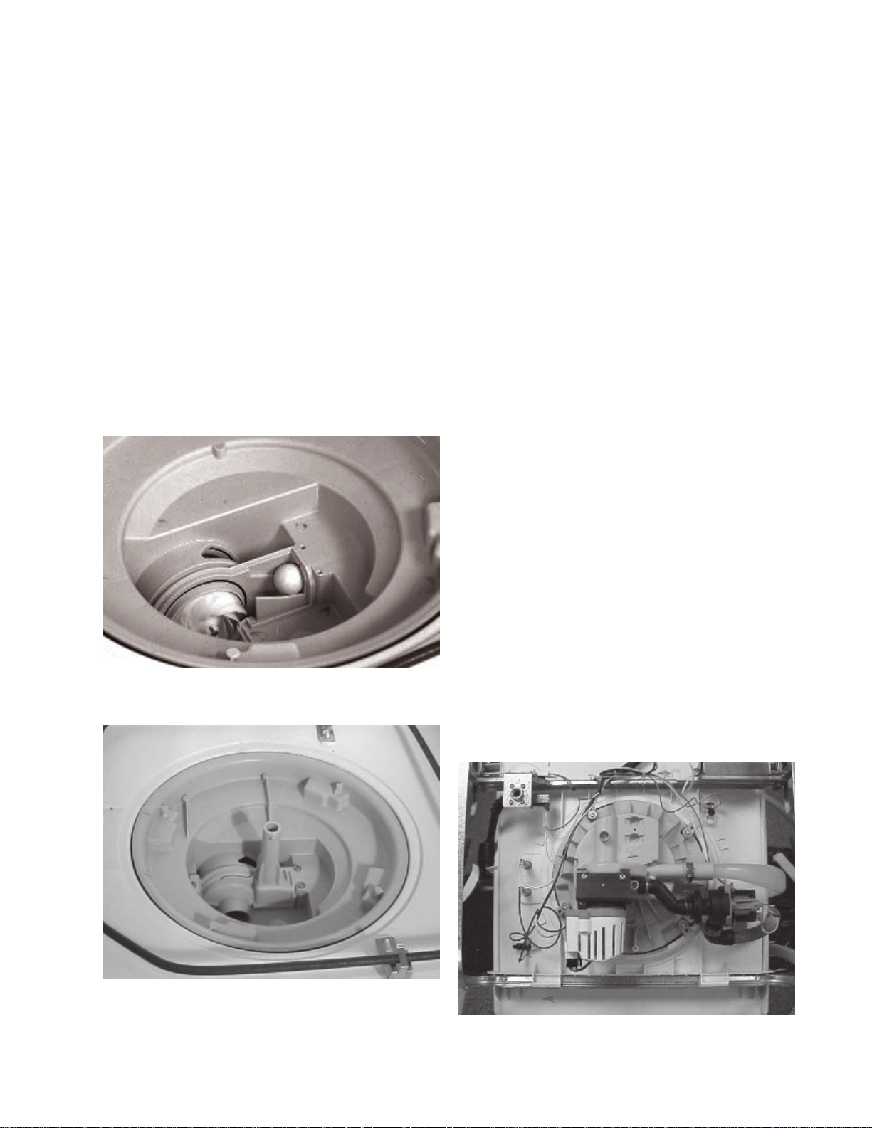
WATER DISTRIBUTION SYSTEM
The water distribution system consists of an upper and
lower spray arm, upper (spray) arm delivery tube, filter,
soil director, pump, sump, and check ball. The system
is designed to operate only one spray arm at a time.
During the first wash and first and second rinses, only
the lower spray arm operates. In the second wash, third
and fourth rinses the spray arms alternate about every
90 seconds.
This alternating of the spray arms is achieved with a
check ball located on a ramp between two outlets of the
pump. There is an outlet to the bottom spray arm and an
outlet to the upper arm delivery tube. In the normal
position the ball is at the bottom of the ramp, in front of
the opening to the upper arm delivery tube.
the ball and enter the tube, and fills the tube at a rate of
approximately four inches a second. At the same time,
the outlet to the lower spray arm is open, so the lower
spray arm operates. When the pump stops, the pressure
is removed from the ball and the water flows down the
tube, forcing the ball up the ramp and against the outlet
to the lower spray arm. If the pump remains off for more
than 3 seconds, all the water in the tube escapes and
the ball returns to the bottom of the ramp. But, if the
pump is started in less than .6 seconds, the water from
the upper arm delivery tube is still forcing the ball up the
ramp against the outlet to the lower spray arm. The
force of the water from the pump continues to hold the
ball against the outlet to the lower spray arm which
leaves the outlet to the upper arm delivery tube open.
When the ball is in this position only the upper spray arm
operates. This momentary stopping of the pump is
controlled by a contact in the timer.
Another unique feature of the water distribution system
is the two cavities of the sump. One cavity provides
filtered water to the pump for recirculation through the
spray arms. The other, called a quiet water cavity,
allows soil to collect in the area of the macerator blade,
where it is held until the drain pump removes it.
When the pump starts, the force of the water pushes the
ball to block the opening to the upper arm delivery tube.
WATER DISTRIBUTION COMPONENTS
Wash Pump
The recirculation (wash) pump has three (3) functional
parts, a 1/12th HP drive motor, impeller, and macerator
blade. The pump circulates water at the rate of 12
gallons per minute. This pump is used only during the
wash cycle, a separate pump is used during the drain
cycle. The wash pump is to be replaced as a complete
assembly.
Not all of the water is blocked however. The opening is
constructed to allow a small amount of water to bypass
Page 13
Page 15
Upper Spray Arm
The upper spray arm hangs from a bracket that is
snapped to the upper rack. The water is supplied to the
arm with a nozzle and funnel arrangement. The nozzle
is located at the top of the tub and the funnel is located
directly below it and directs water into the arm. All the
spray jets but three face up.
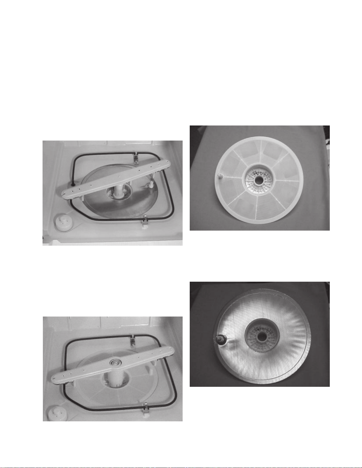
Lower Spray Arm
The lower spray arm rotates on the lower spray arm
support. It has two functions, washing the dishes and
cleaning the filter. The jets located on the top of the arm
clean the dishes and propel the arm. The three (3) jets
located on the bottom of the arm are aimed to flush the
soil on the filter toward the glass trap and soil director.
Filter
Two types of filter materials are used, molded
polypropylene and stainless steel, depending on the
model.
Polyproplene filter
This is a molded filter consisting of two parts; the filter,
which covers the entire sump, plus an inner basket,
which directs food soil to the drain portion of the pump.
The inner basket can be constructed of fine polyester
mesh or polypropylene around the sides of the basket.
The bottoms of both baskets are open to allow the soil
to enter the drain portion of the pump.
Lower Spray Arm With Collapsible Tower
The spray arm rotates 100% of the time with the tower
assembly fully extended during the wash and rinse
cycles. The arm has two functions; washing the dishes
and cleaning the filter. The jets, located on the top of the
arm, clean the dishes and propel the arm. The two jets
located on the bottom of the arm are aimed to flush the
soil on the filter toward the soil director.
Stainless Steel Filter
The stainless steel filter covers the entire sump area
with an inner basket of fine mesh polyester. The bottom
of this basket is open to allow food soil to enter the drain
portion of the pump.
Page 14
Page 16
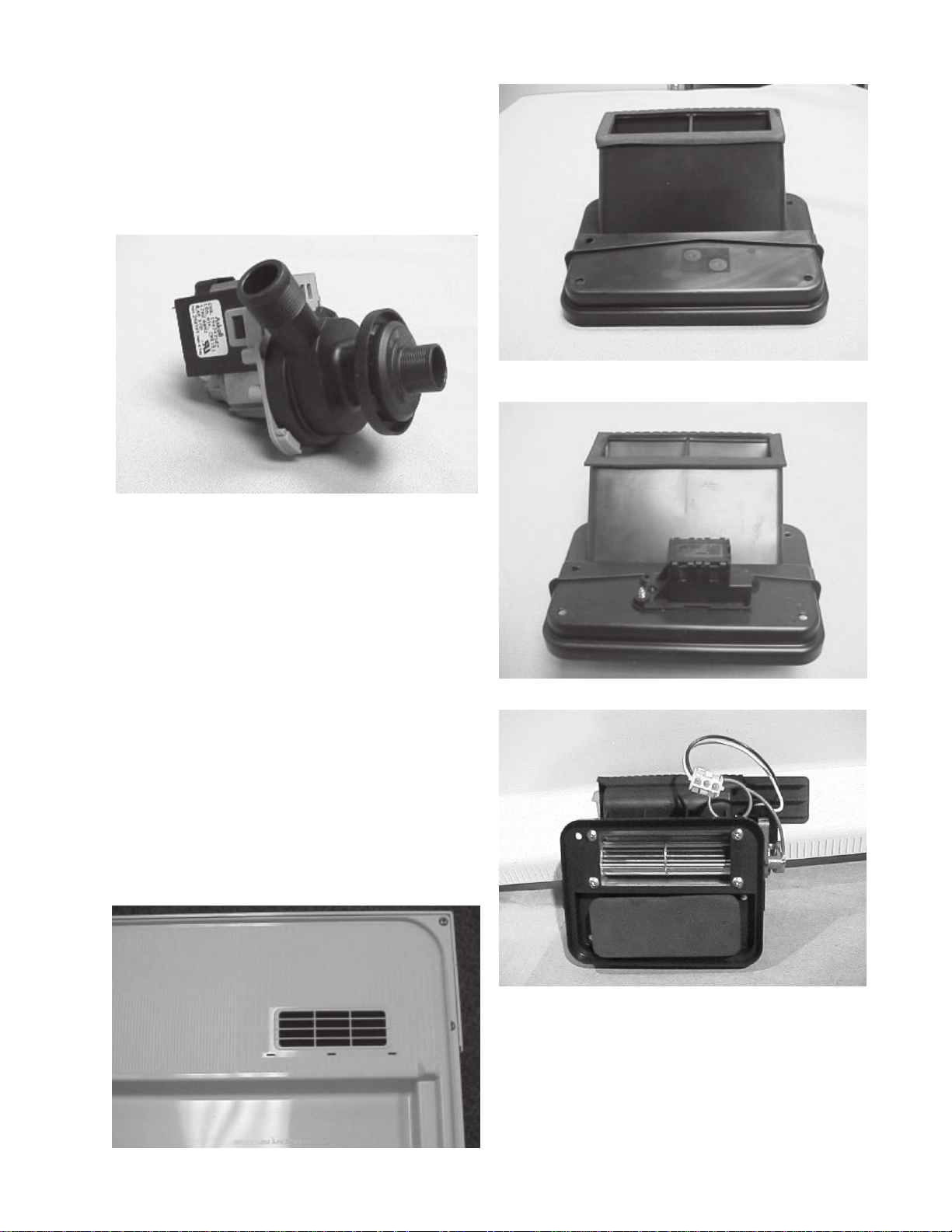
Drain Pump
The only function of the drain pump is to remove water
from the dishwasher. It is driven by a 1/25th HP drive motor.
It consists of 3 function parts; a pump cover, impeller and
armature, and stator. The pump only comes as an
assembly. The pump cover can be removed for easy
cleaning of the pump.
Drying System
Static Vent
The drying system on the dishwasher can employ one
of three types of systems:
1. Static Dry System - The vent is located on the
upper left-hand side of the door and is open at all
times. This allows the warm, moist air to escape out
the vent grill. Air is drawn into the dishwasher tub
through the opening across the bottom of the door.
2. Active Vent System - The vent is closed up until the
start of the dry cycle, at which time the vent is
opened and the warm, moist air is allowed to escape.
Also, the air is brought into the tub through the
bottom of the door.
3. Power Vent System - This system is the same as
the Active Vent System but with the addition of a
blower motor. At the beginning of the dry cycle, the
vent opens and a small motor with a centrifugal
blower starts, accelerating the movement of air
from the dishwasher.
Active Vent
Power Vent
The door vent actuator opens the vent only during the
dry cycle. It is closed during all other cycles to minimize
heat loss and to prevent noise from being transmitted
into the kitchen.
Page 15
Page 17
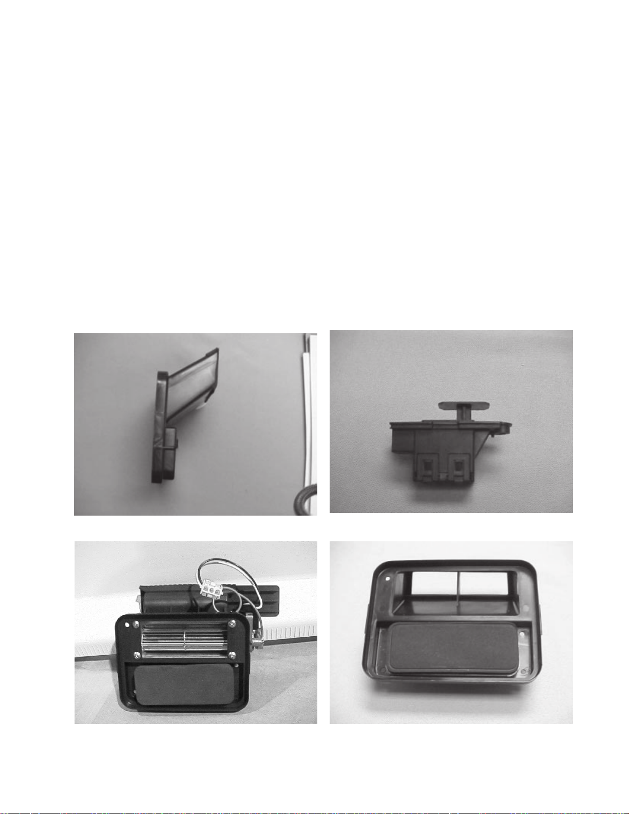
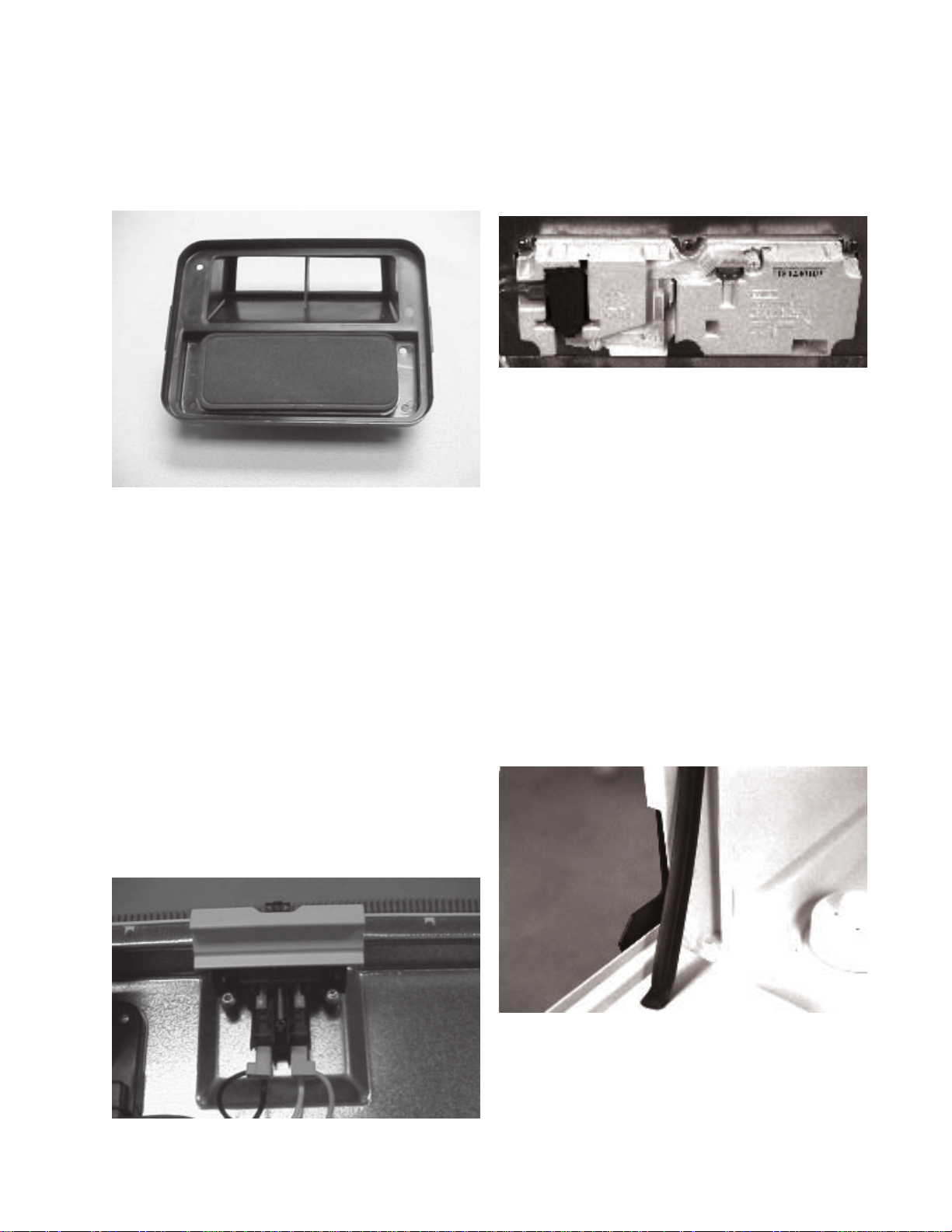
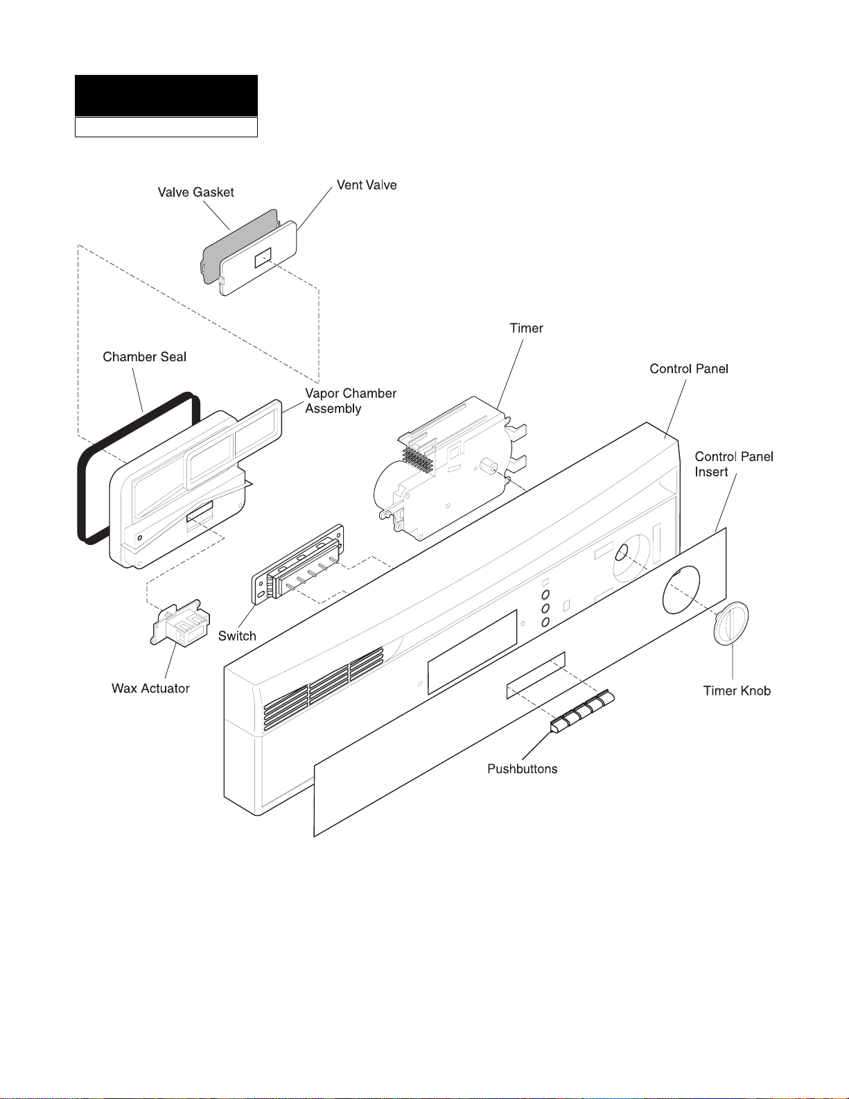
DRYING SYSTEM COMPONENTS
Lower Vent Housing
The lower vent housing is located between the inner
door assembly and control housing and is mounted to
the inner door panel. It surrounds an opening in the
inner door panel. The opening is covered with a moveable
vent valve.
Vent Valve
The vent valve is a rectangular rubber covered pad
slightly larger than the opening. The vent valve is
attached to the vent actuator which is electrically
operated.
Vent Actuator
The actuator is made up of a rod, slide, wax motor , and
spring. The valve is attached to one end of the rod and
the slide is inserted in the other. The spring pushes in
on the slide forcing the rod to push the valve against the
opening in the door panel.
When the timer enters the dry cycle, 120 VAC is applied
to the wax motor. The wax motor is made up of a heating
disk, wax chamber and piston. When voltage is applied
to the heating disk, the wax in the chamber heats
causing the wax to expand, driving the piston out. The
piston forces the slide out causing the vent valve to
open.
The vent actuator is replaced as a complete assembly.
No individual replacement parts are available.
Blower
Models that feature Fan Assisted Dry use a small motor
and centrifugal blower assembly which is mounted to
the top section of the lower vent housing.
Upper Vent Housing
The upper vent Housing is screwed to the blower and
directs air from the blower to the outlet in the console.
Models that do not have a blower use a different upper
vent housing which connects directly to the lower vent
housing.
Upper
Vent
Lower Vent Housing
Lower Vent
Vent Actuator
Blower
Vent Valve
Page 16
Page 18
DISPENSING SYSTEM
Detergent & Rinse Aid Dispenser
The detergent & rinse aid dispenser consists of two
dispensers combined in one housing that are controlled
with one wax motor actuator. The first time the actuator
is energized in a cycle, it dispenses detergent. The
second time the actuator is energized, it dispenses
rinse aid. The amount of rinse aid dispensed can be
adjusted from one to four (1 - 4) by using a pointer under
the fill cap. The dispenser is replaced as a complete
assembly. No individual replacement parts are available.
Dispenser Operation
The dispenser has two detergent cups:
1. A cup with a spring loaded cover with a
manual or automatic release latch.
2. A cup formed in the inner door panel without
a cover.
Prior to starting the dishwasher, detergent is added to
the dispenser cup and the cover is latched close. The
open cup is also filled but empties into the tub as soon
as the door is lifted to the upright position.
The detergent in the covered cup is held until the start
of the second wash. The timer then supplies 120 VAC
to the dispenser actuator for one minute. It takes 30
seconds for the actuator to move the pivot arm far
enough to release the cover. When power is applied to
the actuator, the actuator plunger pushes the end of the
pivot arm down. The pivot arm rotates on the shaft of the
detergent dispenser door latch. As the shaft rotates, it
turns the door latch , releasing the spring loaded cover.
The pivot arm is spring loaded so that when power is
removed, it returns to the normal (horizontal) position.
The other end of the pivot arm has a pin that moves in
a slot(s) of the rinse injector pump arm. The rinse
injector pump arm is slotted in such a way that when the
actuator pushes the lever down the first time to release
the detergent cup cover, the pin moves up but does not
raise the rinse injector pump arm. When the timer
removes power from the actuator, the spring forces the
rinse injector pump arm end of the pivot armdown. The
compond slot in the rinse injector pump arm directs the
pivot arm pin down the front of the rinse injector pump
arm and under a shorter slot in the center of the arm.
When the timer reaches the middle of the final rinse
cycle, it again applies 120 VAC to the dispenser actuator
which forces the pivot arm up at the rinse injector end.
As the pin engages the shorter slot, it raises the rinse
injector pump arm which operatesthe pump. When the
power is removed, the pivot arm spring forces the pin to
the bottom of the slot. A leaf spring pushes the rinse
injector pump arm to the left so that the pin returns to the
original starting position.
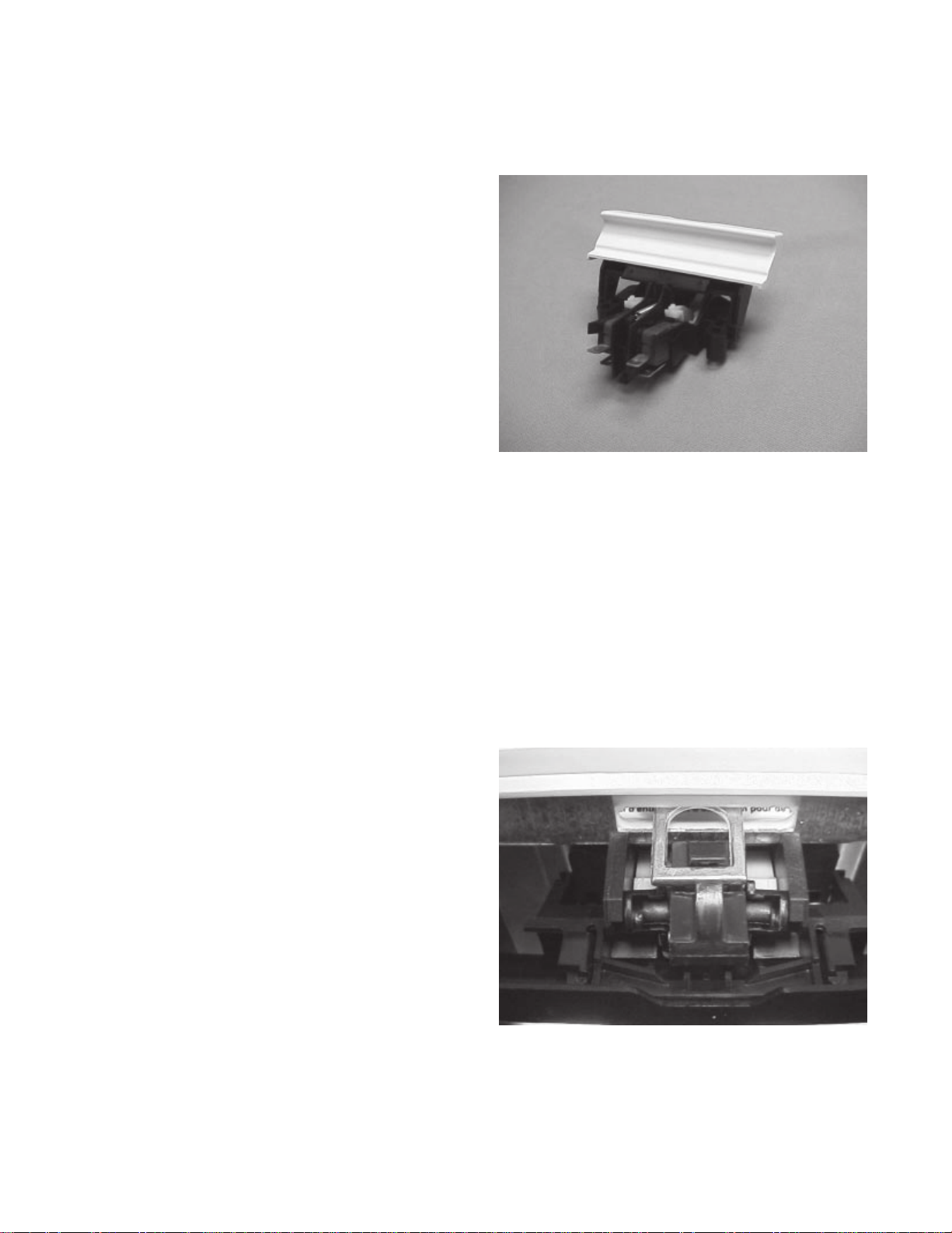
DOOR LATCH ASSEMBLY
The door latch assembly has two functions; one is to
lock the door in a closed position and the other is to
operate the door switches.
The door latch assembly consists of the door handle,
door handle bracket, door catch, door switch bracket,
and door switches. The assembly is secured to the
inner door panel with two locater pins and two screws.
The panel is hidden by and accessed through the
control panel.
When the door is closed, the door strike (mounted on
the tub) forces the spring loaded catch to rotate back
until the bottom of the catch clears the door handle
bracket. At that time, the spring forces the door handle
bracket to rotate. The bar at the top of the door handle
rotates back under the door catch locking the door. The
plunger on the bottom of the bracket rotates forward,
closing the door switches.
The door is released by lifting up on the door handle.
When the handle is lifted up, the door handle bracket
rotates in at the top, allowing the door catch to rotate
open, and out at the bottom to open the door switches.
When the catch is rotated to the open position, it holds
the door handle bracket away from the door switches.
Page 17
Page 19
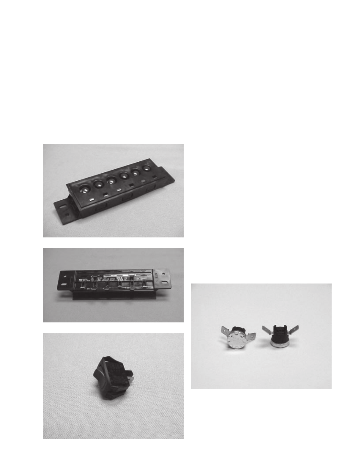
Selector Switch and Thermostats
(Mechanical Timer Models)
Depending on the model, the selector switch could be
a rocker selector switch with two selections or a push
button selector switch with from two to eight buttons and
consisting of from one to four switches.
Heated Dry
If the dishwasher has an option for "Heated Dry", this
switch will be in series with the element. When the timer
advances to the dry portion of the cycle, contacts will
close to apply power to the heating element. When
"ON" is selected, the contacts in the switch will be
closed, applying power to the element. If "OFF" is
selected, the contacts in the switch will be open.
Hi-Temp Wash
The selector switch has a selection for Hi-Temp Wash;
the switch is in parallel with a thermostat mounted on
the bottom of the tub and with a contact in the timer. The
selector switch, temp assure thermostat, and the temp
boost thermostat are all in series with the timer motor.
Both thermostats are normally open thermostats. When
the timer reaches the end of the second wash cycle, the
contact in the timer supplying power to run thetimer
motor will open. At which time, if the selector switch for
the Hi-Temp Wash has been selected, power to run the
timer motor must come through the thermostats. The
temperature of the water in the tub must rise to 137° ±
5° F for the thermostat to close and the timer motor to
advance. If the water temperature is below 137° ± 5° F,
the timer will pause until the heating element raises the
temperature of the water in the tub and allow the
thermostat to close.
Hi-Temp Rinse
If the selector switch was a selection for a Hi-Temp
rinse, the switch is in parallel with a thermostat mounted
in the tub, and the contact in the timer, the same as the
Hi-Temp wash. The operation for the Hi-Temp rinse will
be the same as for the Hi-Temp wash with the exception,
on some models, the temperature of the water in the tub
will be 150° ± 5° F for the thermostat to close to give a
sanitizing rinse.
High Limit Thermostat
The High Limit Thermostat is mounted on the bottom of
the tub in the left rear. This thermostat is a normally
closed thermostat. It is used as a safety in the event of
a component failure in the dishwasher. The thermostat
will open at 200°F and will reset at 100°F.
Page 18
Page 20
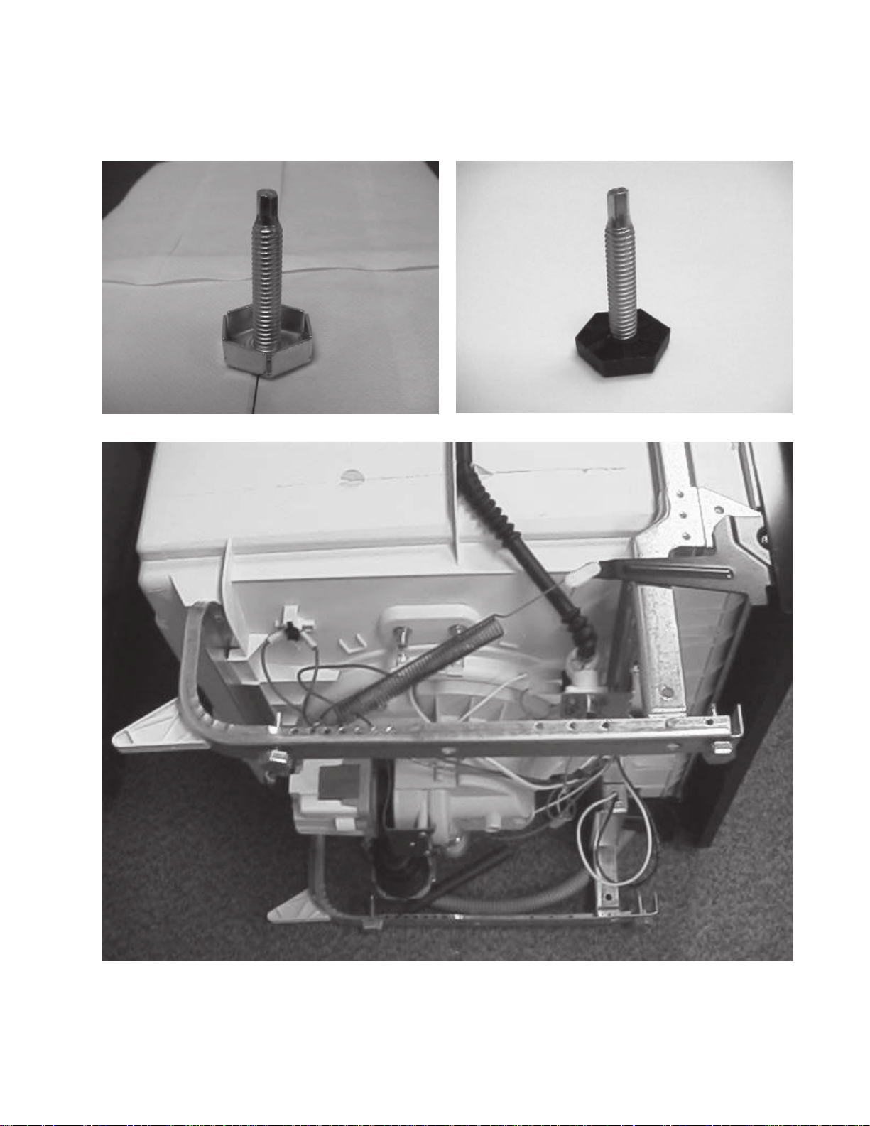
DISHWASHER LEVELING
The dishwasher used four hex shaped leveling legs. They allow the dishwasher to be leveled to any type of
flooring. The tops of the legs are tapered to 3/16" hex so a wrench or socket may be used to adjust the legs from
the top of the leveler.
Page 19
Page 21
DISASSEMBLY
SAFETY PRECAUTIONS
Always turn off the electric power supply before
servicing any electrical component, making ohmmeter
checks, or making any parts replacement. Refer to safe
servicing procedures at the front of this service manual
before servicing the dishwasher.
All voltage checks should be made with a voltmeter
having a full scale range of 130 volts or higher.
After service is completed, be sure all safety grounding
circuits are complete, all electrical connections are
secure, and all access panels are in place.
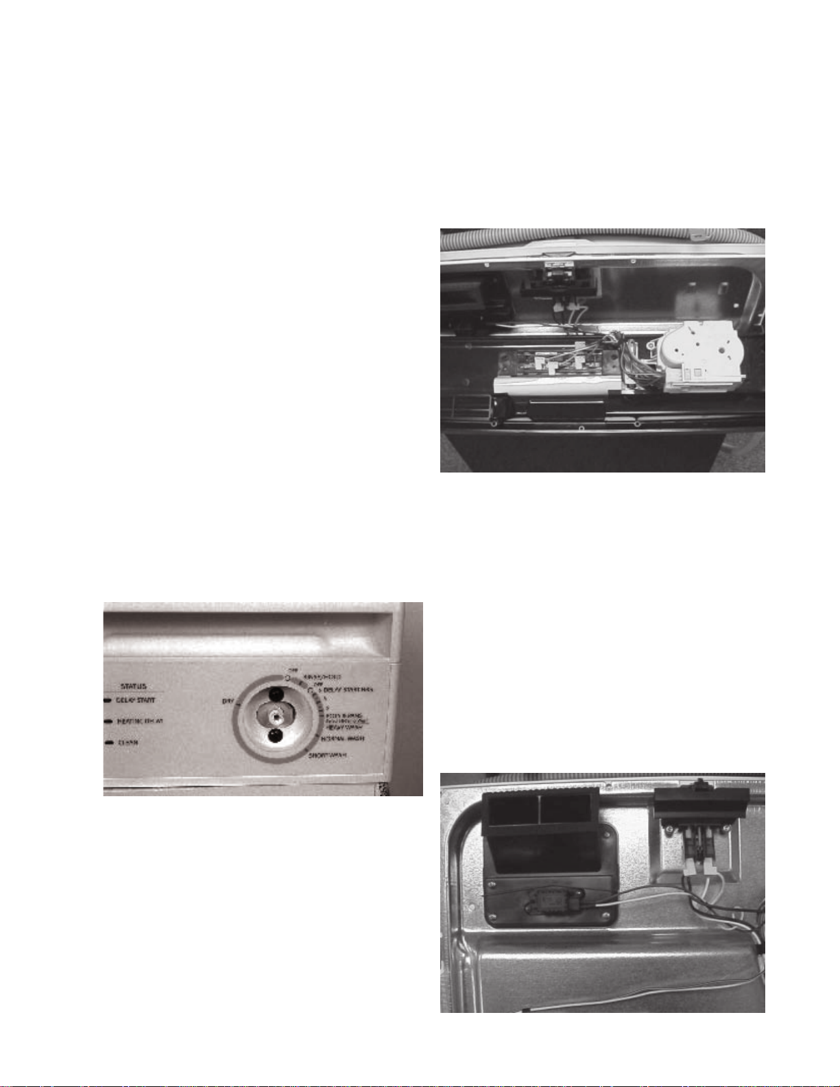
CONTROL PANEL - Mechanical Timer Models
1. Disconnect the dishwasher from electrical supply.
2. Remove six (6) Phillips screws from top of inner
door panel.
TIMER
1. Disconnect dishwasher from electrical supply.
2. Pull timer knob off of timer shaft.
3. Remove control panel.
4. Remove two Phillips screws securing timer to control
panel.
SELECTOR SWITCH
1. Disconnect the dishwasher from electrical supply.
2. Remove control panel.
3. Remove two Phillips screws, one on each end and
lift off switch.
DOOR PANELS - All Models
1. Disconnect dishwasher from electrical supply.
2. The outer door panel is held to the inner door panel
with two locking tabs and two screws. Loosen two
lower screws securing control panel.
3. Remove two screws securing door panel to door
(located at the lower section of the inner door
panel).
4. Slide door panel down and outward to remove.
.
4. Unplug wiring harness plug connector to test or
replace timer.
5. When replacing timer, be sure to transfer protective
plastic covering to new timer.
DISASSEMBLY TIP
When removing the timer knob, slide a lightweight
handerchief between the timer knob and the control
housing. Then work the handkerchief all the way around
the backside of the knob. Then pull on the handkerchief,
pulling the knob off from the rear.
DOOR VENT ASSEMBLY
1. Disconnect dishwasher from electrical supply.
2. Remove outer door panel.
3. Remove control panel.
4. Disconnect wiring to blower motor and vent actuator.
5. Remove four Phillips screws securing vent to inner
door panel.
Page 20
Page 22
VENT VALVE
1. Disconnect the dishwasher from electrical supply.
2. Remove outer door panel.
3. Remove control panel.
4. Slide the vent valve upward to remove from the
actuator arm.
VENT ACTUATOR
1. Remove the door vent assembly..
2. Remove vent valve.
3. Remove two Phillips screws. Slide actuator from
vent housing.
VENT BLOWER
1. Remove the door vent assembly.
2. Remove the two (2) screws securing the top vent
piece.
3. Remove the four (4) screws securing the lower
vent to the blower motor.
DOOR LATCH ASSEMBLY
1. Disconnect dishwasher from electrical supply.
2. Remove outer door panel.
3. The door latch is held to the inner door panel
with two screws and two locator pins. Remove
screws and pull to remove.
DETERGENT / RINSE AID DISPENSER
1. Disconnect dishwasher from electrical supply.
2. Remove outer door panel.
3. Disconnect wiring.
4. Remove six Phillips screws and carefully push
dispenser into tub.
INNER DOOR PANEL
1. To replace inner door panel, remove control
panel, door vent, dispenser and latch.
2. Remove two bolts (T-25 TORX®) from each
hinge and lift off.
3. Remove two bolts and nuts holding "C" arms to
inner door panel.
DOOR SEAL
1. To remove seal, lift one end and pull entire seal
out.
2. To replace or reinstall seal, center white mark on
back of seal into center top of seal recess and
press seal into place.
3. Go to bottom and form seal into seal recess
making the "L" in the tub. Repeat for remaining
side.
4. Push seal into recess in 5 places up one side to
center top. Repeat for remaining side.
5. Close door and let door set seal into recess.
Page 21
Page 23
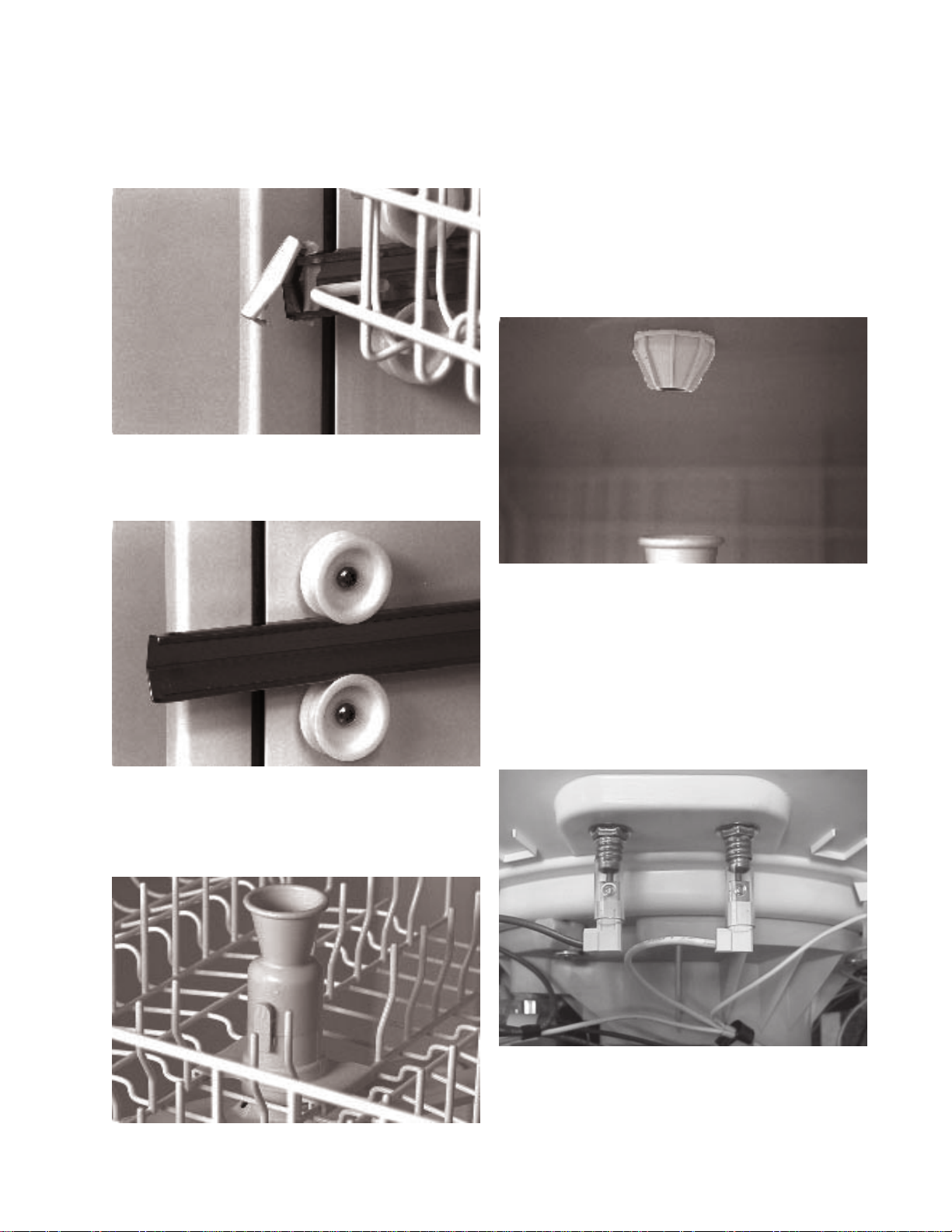
UPPER RACK
1. To remove rack, unsnap and remove retainers at
end of metal track. Once retainers are removed,
pull rack straight out.
2. Each rack roller is secured with a T-25 TORX®
bolt.
UPPER SPRAY ARM
1. To remove upper spray arm, unscrew plastic nut
securing it to support.
WATER DISTRIBUTOR
1. The water distributor (nozzle) is screwed to the
top of the upper arm delivery tube. A rubber seal
is used on the top side of the tub to eliminate
leaks.
2. Water distribtor (nozzle) is a right-hand thread
that screws counterclockwise.
UPPER WATER TUBE
1. To remove upper water tube, press in on top of
two clips and lift up.
KICK PLATE
1. To remove kick plate and insulation (some models)
remove two Phillips screws and pull out on bottom
of kick plate.
HEATING ELEMENT
1. Disconnect dishwasher from electrical supply.
2. To remove element, disconnect wiring and remove
two element mounting nuts.
3. Lift terminal ends of element into tub and rotate
element sideways, out of retainers.
Page 22
Page 24
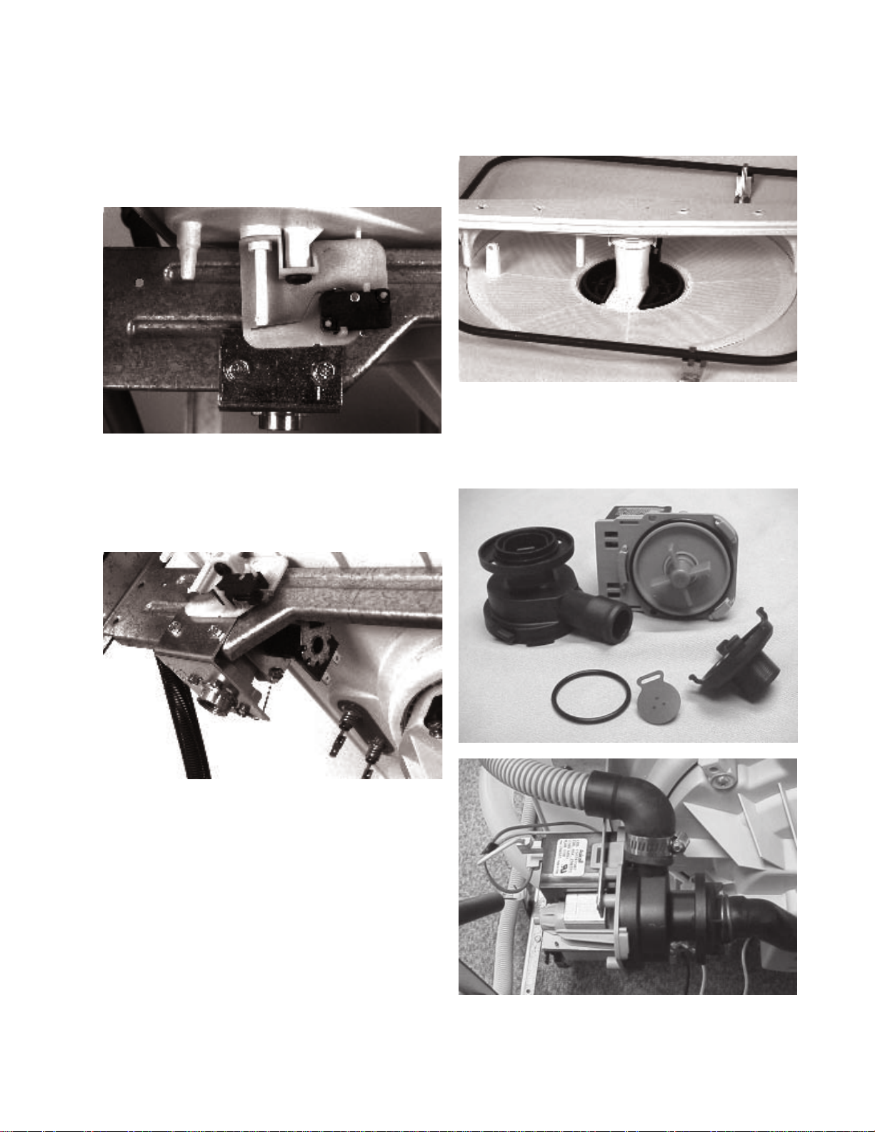
FLOAT SWITCH AND BRACKET
1. Disconnect dishwasher from electrical supply.
2. To remove float switch bracket, remove outer door
panel, kick plate, and wires to float switch. A single
Phillips screw secures the bracket to the tub.
3. Remove float switch by spreading mounting clips.
WATER VALVE
1. Disconnect dishwasher from electrical supply.
2. Remove outer door panel, kick plate, and wires.
3. Water valve is secured with two 5/16" hex screws.
GLASS TRAP
1. To remove glass trap, lift handle up and raise
trap up and out of sump.
LOWER SPRAY ARM SUPPORT
1. To remove lower spray arm support, remove
spray arm and glass trap, then turn support 90°
clockwise and lift up.
DRAIN PUMP
1. Disconnect dishwasher from electrical supply.
2. Remove outer door panel and kick plate.
3. Remove hoses and wiring to drain pump.
4. Remove two screws securing drain pump to
mounting bracket.
5. Front housing can be removed by lifting lock tab
and turning housing counterclockwise about 45°
and lifting off.
LOWER SPRAY ARM
1. To remove lower spray arm, pull out on retaining
clips and lift up.
Page 23
Page 25
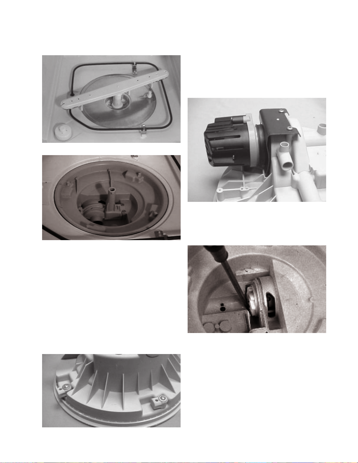
FILTER
1. To remove filter, remove glass trap, spray arm and
spray arm support. Lift filter up to remove.
PUMP COVER
1. To remove pump cover, remove glass trap, spray
arm, spray arm support and filter.
2. Remove three T-20 TORX
® bolts and lift cover off.
3. Remove two T-20 TORX® screws on bottom of
bracket.
4. Place flat blade screwdriver between bracket and
sump, then lift bracket out of sump.
MOTOR AND IMPELLER
1. Disconnect dishwasher from electrical supply.
2. To remove motor, remove pump housing, motor
mounting bracket, and pump cover.
PUMP AND MOTOR ASSEMBLY
1. To remove pump and motor assembly, disconnect
dishwasher from electrical supply. Remove glass
trap, spray arm, spray arm support and filter.
2. Remove outer door panel and kick plate.
3. Disconnect delivery tube and sump drain hose.
4. Pump and motor assembly is secured in place
using four retainers that rotate easily. Turn retainers
90° and lift assembly from inside of tub.
5. Remove electric wires from motor.
MOTOR MOUNTING BRACKET
1. Disconnect dishwasher from electrical supply.
2. To remove motor and motor mounting bracket, first
remove pump and motor assembly.
3. Place large screwdriver between housing and
impeller and force impeller and motor out of housing.
DO NOT ROCK MOTOR TO RELEASE.Lubricate
with Vaseline® when reinstalling.
Page 24
Page 26

THERMOSTATS
1. Disconnect dishwasher from electrical supply.
2. To remove either thermostat, remove outer door
panel and kick plate.
3. Thermostats are located behind electrical junction
box. To remove thermostat, loosen single Phillips
screw, turn retainer, and drop thermostat from tub.
4. Remove wire from thermostat.
NOTE: When reinstalling thermostats, apply
thermal mastic to the face of the thertmostat.
INDICATOR LAMPS - Mechanical Timer Models
1. Disconnect dishwasher from electrical supply.
2. To remove an indicator lamp, drop control panel
and rotate indicator. Lift out of mounting bracket.
NOTE: Indicators are part of the wiring harness
and are not available separately.
HIGH LIMIT THERMOSTAT (ON TUB BOTTOM)
1. Disconnect dishwasher from electrical supply.
2. Disconnect wires from thermostat and remove single
Phillips screw.
3. Determine failure causing high limit thermostat to
open before replacing.
Page 25
Page 27

TROUBLESHOOTING TIPS
SYMPTOM
Dishwasher will not operate
when turned on.
Motor hums but will not start or
run.
Motor trips out on internal
thermal overload protector.
CHECK THE FOLLOWING
1. Fuse (blown or tripped).
2. 120 VAC supply wiring
connection faulty.
3. Motor (inoperative, check
resistances).
4. Door Switch (open contacts).
5. Door latch not making contact
with door switch.
1. Motor (bad bearings or locked
rotor).
2. Motor stuck due to prolonged
non-use.
3. Motor fan blocked.
1. Improper voltage.
2. Seal faces binding.
3. Motor windings shorted.
4. Glass or foreign items in pump.
REMEDY
1. Replace fuse or reset breaker.
2. Repair or replace wire
fasteners at dishwasher
junction box.
3. Replace motor / impeller
assembly.
4. Replace door switch.
5. Replace latch assembly.
1. Replace motor.
2. Rotate motor fan or impeller.
3. Check/clear fan area.
1. Check voltage.
2. Rotate motor fan or impeller, or
replace.
3. Replace motor/pump
assembly.
4. Clean and clear blockage.
Dishwasher runs but will not
heat.
Detergent cover will not latch or
open.
Dishwasher will not pump out.
1. Hi-limit thermostat open.
2. Heater element (open).
3. Wiring or terminal defective.
1. Excess detergent on lid catch.
2. Latch mechanism defective.
3. Wiring or terminal defective.
4. Broken spring(s).
5. Defective actuator.
1. Drain restricted.
2. Defective drain pump.
3. Air lock in drain hose.
4. Blocked impeller.
5. Open windings.
6. Wiring or terminal defective.
Page 26
1. Replace thermostat.
2. Replace heater element.
3. Repair or replace.
1. Clean catch area.
2. Replace dispenser.
3. Repair or replace.
4. Replace dispenser.
5. Replace actuator.
1. Clear restrictions.
2. Replace pump.
3. Drain hose must slope upward
to side of tub. Hose must be
attached on side of tub.
4. Check for blockage and clear.
5. Replace windings.
6. Repair or replace.
Page 28

SYMPTOM REMEDY
CHECK THE FOLLOWING
Dishwasher will not fill with
water.
Dishwasher water siphons out.
Detergent left in dispenser.
1. Water supply turned off.
2. Defective water inlet valve.
3. Check fill valve screen for
obstructions.
4. Defective float switch.
5. Wiring or terminal defective.
6. Float stuck in "UP" position.
1. Drain hose not connected to
side of tub.
2. Drain hose (high) loop too low.
3. Drain line connected to a floor
drain not vented.
1. Detergent allowed to stand too
long in dispenser.
2. Dispenser wet when detergent
was added.
3. Detergent cover held closed or
blocked by large dishes.
4. Improper incoming water
temperature to properly
dissolve detergent.
5. See "Detergent Cover Will Not
Open."
1. Turn water supply on.
2. Replace water inlet fill valve.
3. Disassemble and clean screen.
4. Repair or replace.
5. Repair or replace.
6. Clean float.
1. Reattach drain hose.
2. Repair to proper height.
3. Install air gap at counter top.
1. Instruct customer/user.
2. Instruct customer/user.
3. Instruct customer/user on
proper loading of dishes.
4. Incoming water temperature
of 120°F is required to properly
dissolve dishwashing
detergent.
Page 27
Page 29

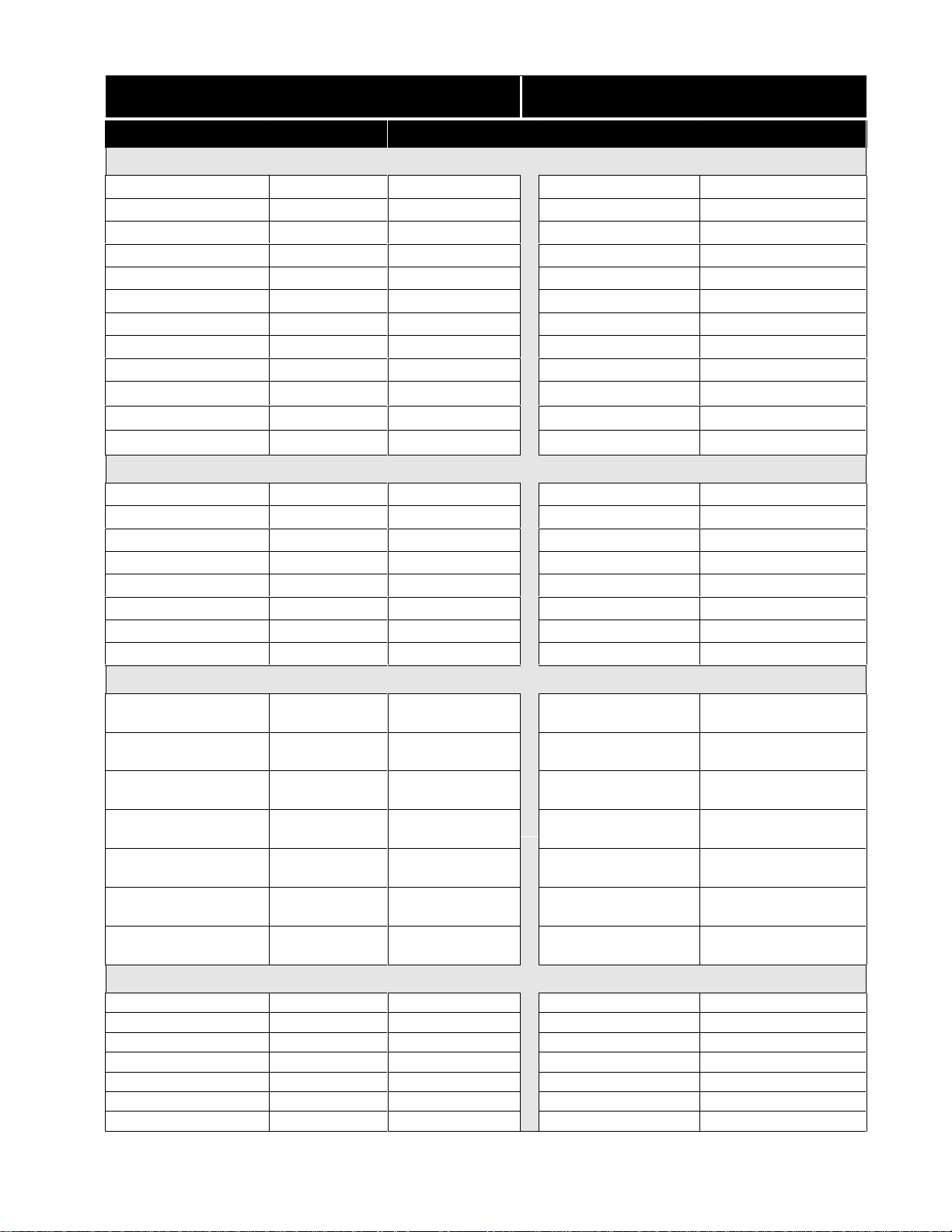
APPENDIX A
Exploded Views Location Chart
Model
Number
FDB125RH*2 A - 9 A - 17 A - 20 A - 23 A - 29 A - 35
FDB345LF*2 A - 10 A - 18 A - 20 A - 24 A - 29 A - 32
FDB421RF*6 ******
FDB421RF*7 ******
FDB435RFR*6 ******
FDB435RFS*4 ******
FDB634CF*4 A - 11 A - 18 A - 20 A - 24 A - 29 A - 32
FDB635RF*6 A - 11 A - 18 A - 20 A - 24 A - 29 A - 32
FDB641RA*0 ******
FDB641RJ*1 ******
FDB657RJ*1 ******
FDB658RA*0 ******
FDP635RF*5 A - 11 A - 18 A - 19 A - 24 A - 25 A - 32
FDP641RA*0 ******
GLDB653A*0 ******
Control
Panel
Door Tub
Motor &
Pump
Frame Racks
GLDB653J*2 A - 11 A - 17 A - 20 A - 24 A - 29 A - 32
GLDB656J*1 A - 3 A - 17 A - 20 A - 24 A - 29 A - 33
GLDB756A*0 ******
GPDB698J*1 A - 6 A - 16 A - 20 A - 24 A - 30 A - 34
MDB122RF*2 A - 14 A - 18 A - 20 A - 24 A - 27 A - 31
MDB124BA*0 ******
MDB124BJ*1 A - 14 A - 17 A - 20 A - 24 A - 27 A - 31
MDB124BH*1 A - 14 A - 17 A - 20 A - 24 A - 27 A - 31
MDB125RH*2 A - 9 A - 17 A - 20 A - 23 A - 29 A - 35
F71C12PH*1 ******
F7C24RJ*1 ******
ADW350RA*0 A - 5 A - 15 A - 20 A - 21 A - 28 A - 31
ADW350RA*1 A - 12 A - 17 A - 20 A - 24 A - 27 A - 31
* Information not available - Parts Catalogs not created as of this Publication date
A - 1
Page 30
APPENDIX A (continued)
Exploded Views Location Chart
Model
Number
ADW550RA*0 A - 7 A - 15 A - 20 A - 21 A - 28 A - 32
ADW550RA*1 A - 13 A - 17 A - 20 A - 24 A - 30 A -32
ADW650RA*0 A - 7 A - 15 A - 20 A - 21 A - 28 A - 33
ADW650RA*1 A - 7 A - 17 A - 20 A - 24 A - 28 A - 33
ADW650RA*2 A - 13 A - 17 A - 20 A - 21 A - 30 A - 33
GDP635RH*2 A - 11 A - 18 A - 19 A - 24 A - 25 A - 32
GDB742RJ*0 A - 8 A - 19 A - 20 A - 22 A - 26 A - 31
GDB742RJ*1 ******
GDB755RJ*0 A - 4 A - 17 A - 20 A - 22 A - 26 A - 32
GDB755RJ*1 A - 13 A - 17 A - 20 A - 24 A - 27 A - 32
Control
Panel
Door Tub
Motor &
Pump
Frame Racks
* Information not available - Parts Catalogs not created as of this Publication date
A - 2
Page 31

CONTROL PANEL
For Model #
GLDB656J*1
A - 3
Page 32

CONTROL PANEL
For Model #
GDB755RJ*0
A - 4
Page 33

CONTROL PANEL
For Model #
ADW350RA*0
A - 5
Page 34

CONTROL PANEL
For Model #
GPDB698RJ*1
A - 6
Page 35

CONTROL PANEL
For Model #'s
ADW550RA*0
ADW650RA*0
ADW650RA*1
A - 7
Page 36

CONTROL PANEL
For Model #
GDB742RJ*0
A - 8
Page 37

CONTROL PANEL
For Model #'s
FDB125RH*2
MDB125RH*2
A - 9
Page 38
CONTROL PANEL
For Model #
FDB345LF*2
A - 10
Page 39

CONTROL PANEL
For Model #'s
FDB634CF*4
FDB635RF*6
FDP635RF*5
GDP635RH*2
GLDB653J*2
A - 11
Page 40

CONTROL PANEL
For Model #
ADW350RA*1
A - 12
Page 41

CONTROL PANEL
For Model #'s
ADW550RA*1
ADW650RA*2
GDB755RJ*1
A - 13
Page 42

CONTROL PANEL
For Model #'s
MDB122RF*2
MDB124BJ*1
MDB124BH*1
A - 14
Page 43

DOOR
For Model #'s
ADW350RA*0
ADW550RA*0
ADW650RA*0
A - 15
Page 44

DOOR
For Model #
GPDB698J*1
A - 16
Page 45

ADW350RA*1
ADW650RA*2
ADW550RA*1
ADW650RA*1
FDB125RH*2
DOOR
For Model #'s
GLDB653J*2
GLDB656J*1
GDB742RJ*0
GDB755RJ*0
GDB755RJ*1
MDB124BJ*1
MDB124BH*1
MDB125RH*1
A - 17
Page 46

FDB345CF*2
FDB634CF*4
DOOR
For Model #'s
FDB635RF*6
FDP635RF*5
GDP635RH*2
MDB122RF*2
A - 18
Page 47

TUB
For Model #'s
FDP635RF*5
GDP635RH*2
A - 19
Page 48

ADW350RA*0
ADW350RA*1
ADW550RA*0
ADW550RA*1
ADW650RA*0
ADW650RA*1
ADW650RA*2
FDB125RH*2
TUB
For Model #'s
FDB345LF*2
FDB634CF*4
FDB635RF*6
GDB742RJ*0
GDB755RJ*0
GDB755RJ*1
GLDB653J*2
GLDB656J*1
GPDB698J*1
MDB122RF*2
MDB124BJ*1
MDB124BJ*1
MDB124BH*1
MDB125RH*2
A - 20
Page 49

MOTOR & PUMP
For Model #'s
ADW350RA*0
ADW550RA*0
ADW650RA*0
ADW650RA*2
A - 21
Page 50

MOTOR & PUMP
For Model #'s
GDB742RJ*0
GDB755RJ*0
A - 22
Page 51

MOTOR & PUMP
For Model #'s
FDB125RH*2
MDB125RH*2
A - 23
Page 52

ADW350RA*1
ADW550RA*1
ADW650RA*2
FDB345LF*2
FDB634CF*4
MOTOR & PUMP
For Model #'s
FDB635RF*6
FDP635RF*5
GDB755RJ*1
GDP635RH*2
GLDB653J*2
GLDB656J*1
GPDB698J*1
MDB122RF*2
MDB124BJ*1
MDB124BH*1
A - 24
Page 53

FRAME
For Model #'s
FDP635RF*5
GDP635RH*2
A - 25
Page 54

FRAME
For Model #'s
GDB742RJ*0
GDB755RJ*0
A - 26
Page 55

FRAME
For Model #'s
ADW350RA*1
GDB755RJ*1
MDB122RF*2
MDB124BJ*1
MDB124BH*1
A - 27
Page 56

FRAME
For Model #'s
ADW350RA*0
ADW550RA*0
ADW650RA*0
ADW659RA*1
A - 28
Page 57

FRAME
For Model #'s
FDB125RH*2
FDB345LF*2
FDB634CF*4
FDB635RF*6
GLDB653J*2
GLDB656J*1
MDB125RH*2
A - 29
Page 58

FRAME
For Model #'s
ADW550RA*1
ADW650RA*2
GPDB698J*1
A - 30
Page 59

RACKS
For Model #'s
ADW350RA*0
ADW350RA*1
GDB742RJ*0
MDB122RF*2
MDB124BJ*1
MDB124BH*1
A - 31
Page 60

RACKS
For Model #'s
ADW550RA*0
ADW550RA*1
FDB345LF*2
FDB634CF*4
FDB635RF*6
FDP635RF*5
GDP635RH*2
GDP755RJ*0
GDP755RJ*1
GLDB653J*2
A - 32
Page 61

RACKS
For Model #'s
ADW650RA*0
ADW650RA*1
ADW650RA*2
GLDB656J*1
A - 33
Page 62

RACKS
For Model #
GPDB698J*1
Page 63

RACKS
For Model #'s
FDB125RH*2
MDB125RH*2
Page 64

APPENDIX B
SERVICE DATA SHEETS
SERVICE DATA SHEET # PAGE
154370901 B - 1
154374001 B - 2
154374101 B - 3
154382801 B - 4
154382901 B - 5
154383001 B - 6
154385401 B - 7
154390501 B - 8
154395901 B - 9
154396001 B- 10
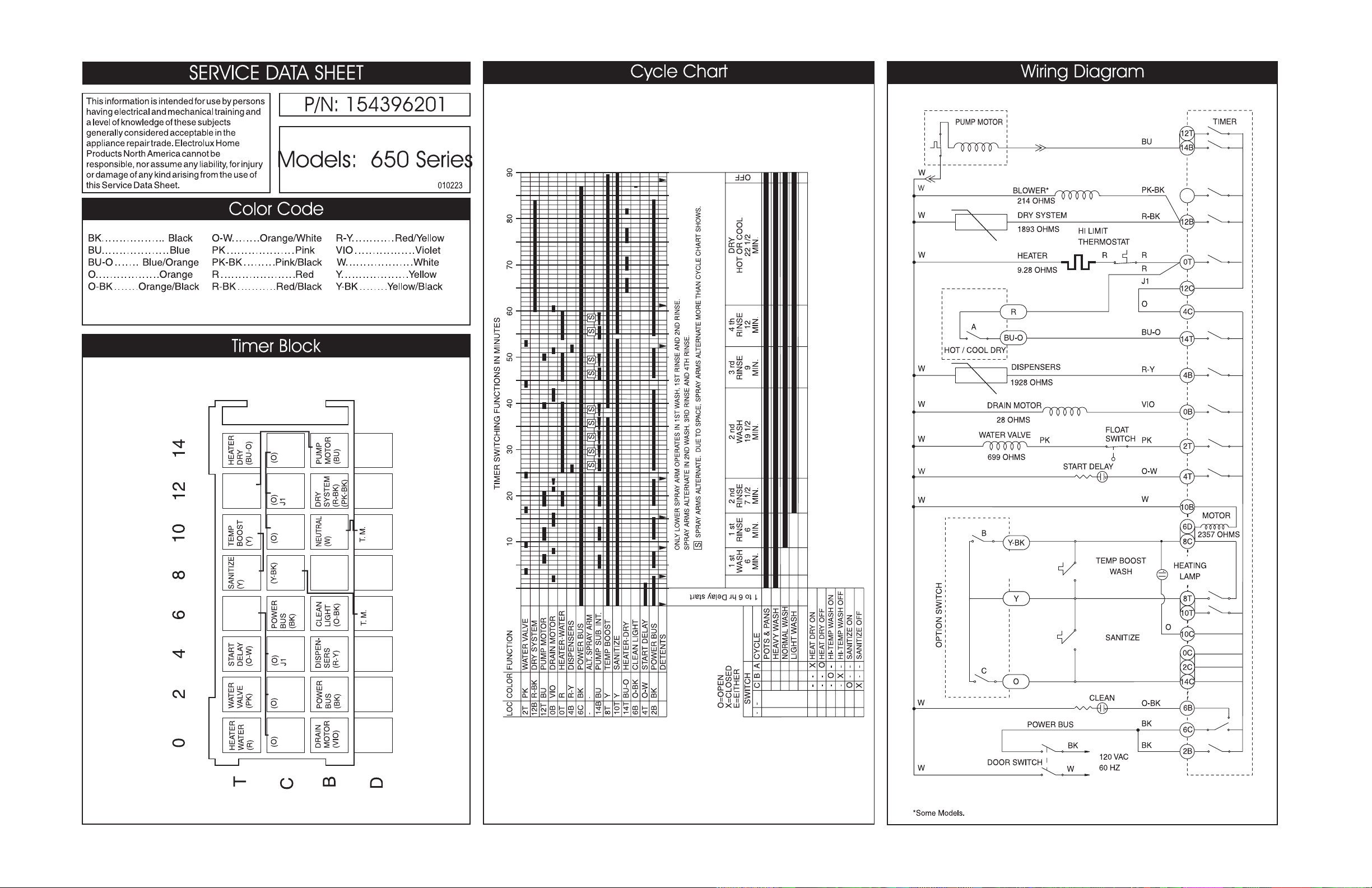
154396201 B - 11
154396301 B - 12
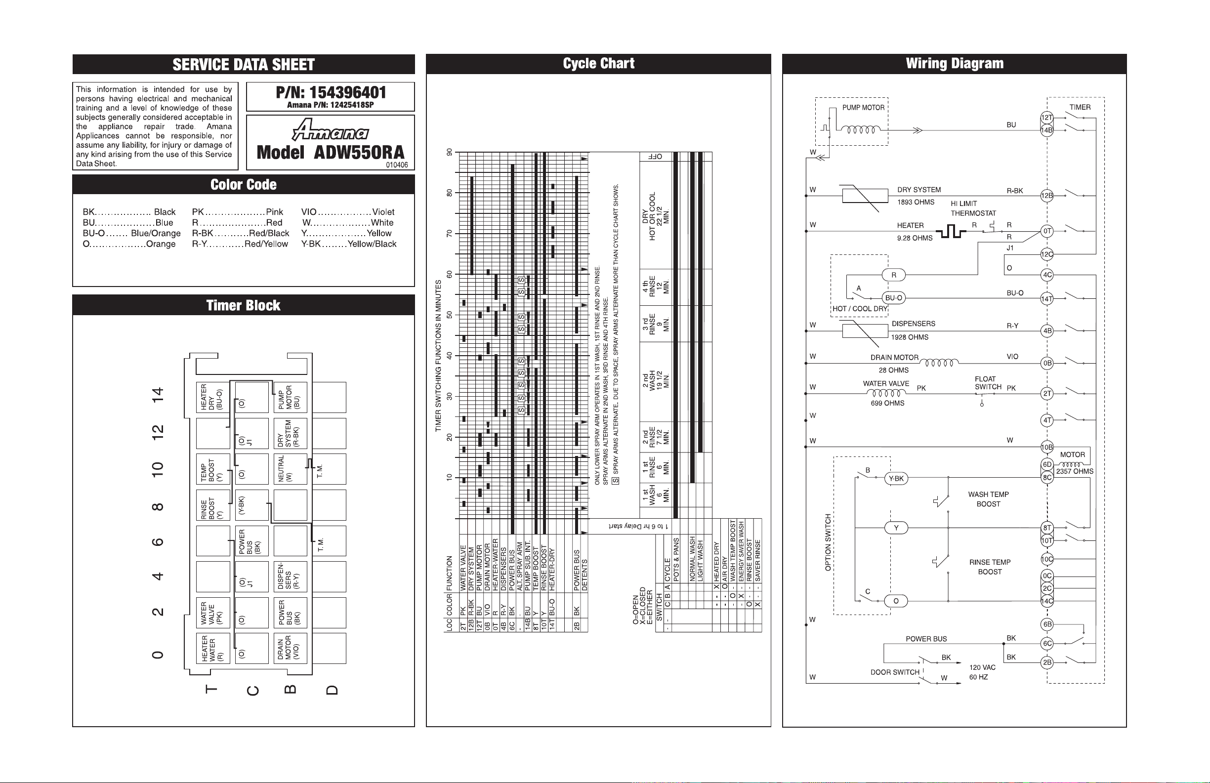
154396401 B - 13
154396501 B - 14
154396801 B - 15
154400501 B - 16
154402401 B - 17
154402501 B - 18
154403001 B - 19
154403801 B - 20
154405901 B - 21
154407901 B - 22
Page 65

B-1
Page 66

B-2
Page 67

B-3
Page 68

B-4
Page 69

B-5
Page 70

B-6
Page 71

B-7
Page 72

B-8
Page 73

B-9
Page 74

B-10
Page 75
B-11
Page 76

B-12
Page 77
B-13
Page 78

B-14
Page 79

B-15
Page 80

B-16
Page 81

B-17
Page 82

B-18
Page 83

B-19
Page 84

B-20
Page 85

B-21
Page 86

B-22
 Loading...