

Page 1
© ELECTROLUX ITALIA S.p.A.
Spares Operations Italy
Corso Lino Zanussi, 30
I - 33080 PORCIA /PN (ITALY)
Fax +39 0434 394096
Publication no.
599 72 40-80
Edition: 12-2009
EN
SERVICE MANUAL
WASHING
WM-WD
Front loader
Platform
EWM1000
EWM1000plus
EWM2000evo
EWM3000new
ENV06
11xx21xx
25xx/35xx
Page 2

QUICK GUIDE AND APPLIANCES LIST 2/176 599 72 40-80
Page 3

Content
EWM1000 ............................................................................................................................................5
1
1.1 Access to the diagnostic cycle ....................................................................................................5
1.2 Rapid reading of alarms..............................................................................................................5
1.3 Cancelling the last alarm.............................................................................................................5
1.4 Phases of the diagnostics test.....................................................................................................6
1.5 Reading the alarms.....................................................................................................................7
1.5.1 Display ing th e alarm..............................................................................................................7
1.5.2 Examples of alarm display.....................................................................................................7
1.5.3 Status of alarms during the diagnostics cycle ......................................................................... 7
1.6 Table of alarms codes EWM1000 ...............................................................................................8
1.6.1 Notes concerning cer tain alarm codes...................................................................................9
1.7 Elementary diagram..................................................................................................................10
1.7.1 With instantaneous door l oc k ing device...............................................................................10
1.8 With PTC door locking dev ic e ...................................................................................................11
1.8.1 Key to circuit diagram..........................................................................................................12
1.9 Connectors on circ uit board EWM1000.....................................................................................13
1.10 Burning on the ci rcuit boar d EWM 1000 ..................................................................................... 14
1.10.1 EWM1000...........................................................................................................................14
1.10.2 Components side (common)................................................................................................ 14
1.10.3 Pushbutton – led side (horizontal buttons)...........................................................................15
1.10.4 Pushbutton – led side (vertical buttons) ............................................................................... 15
2 EWM1000plus 2000ev o 3000new.....................................................................................................16
2.1 Control panel ............................................................................................................................ 16
2.2 Sigma/Alpha/Ellipse//Multipanel Built-In/Sigm a- ZK/Jewel with or without selector......................17
2.2.1 Access to diagnostic s system.............................................................................................. 17
2.2.2 Rapid reading of alarm codes.............................................................................................. 17
2.2.3 Cancelling the last alarm.....................................................................................................17
2.3 AEG NexXxt Version wit h sel ec tor and incorporated ON/OFF swit c h......................................... 18
2.3.1 Access to diagnostic s system.............................................................................................. 18
2.3.2 Rapid reading of alarm codes.............................................................................................. 18
2.3.3 Cancelling the last alarm.....................................................................................................18
2.4 AEG New Version with right selector and incorporat ed ON/OFF switc h ..................................... 19
2.4.1 Access to diagnostic s system.............................................................................................. 19
2.4.2 Rapid reading of alarm codes.............................................................................................. 19
2.4.3 Cancelling the last alarm.....................................................................................................19
2.5 DELTA Version without selector and button ON/OFF switch......................................................20
2.5.1 Access to diagnostic s system.............................................................................................. 20
2.5.2 Rapid reading of alarm codes.............................................................................................. 20
2.5.3 Cancelling the last alarm.....................................................................................................20
2.6 CLUB DISPLAY Version with selector and incorpor ated ON/OFF switch...................................21
2.6.1 Access to diagnostic s system.............................................................................................. 21
2.6.2 Rapid reading of alarm codes.............................................................................................. 21
2.6.3 Cancelling the last alarm.....................................................................................................21
2.7 LCD Version without sel ec tor and button ON/OFF switch..........................................................22
2.7.1 Access to diagnostic s system.............................................................................................. 22
2.7.2 Rapid reading of alarm codes.............................................................................................. 22
2.7.3 Cancelling the last alarm.....................................................................................................22
2.8 LCD Version with selector and button ON/OFF switch...............................................................23
2.8.1 Access to diagnostic s system.............................................................................................. 23
2.8.2 Rapid reading of alarm codes.............................................................................................. 23
2.8.3 Cancelling the last alarm.....................................................................................................23
2.9 Phases of the diagnostics test...................................................................................................24
2.10 Reading the alarm c odes ..........................................................................................................26
2.10.1 Display ing th e alarm............................................................................................................26
2.10.2 Examples of alarm displays ................................................................................................. 26
2.11 Table of alarms codes EWM 1000plus EWM2000EVO EWM3000NEW.................................27
2.12 Basic circuit diagr am EWM 1000P LUS....................................................................................... 31
2.12.1 Diagram (wit hout aqua control)............................................................................................31
2.12.2 Key to circuit diagram..........................................................................................................32
2.12.3 Diagram (wit h aqua c ontrol).................................................................................................33
2.12.4 Key to circuit diagram..........................................................................................................34
2.13 Basic circuit diagr am with sensor EWM2000EVO......................................................................35
QUICK GUIDE AND APPLIANCES LIST 3/176 599 72 40-80
Page 4

2.13.1 Key for circ u i t d iag r am.........................................................................................................36
2.14 Basic circuit diagr am with sensor EWM3000NEW..................................................................... 37
2.14.1 Key for circ u i t d iag r am.........................................................................................................38
2.15 Connectors on circ uit board EWM1000plus...............................................................................39
2.16 Burning on the ci rcuit boar d EWM 1000plus ............................................................................... 40
3 ENV 06...............................................................................................................................................41
3.1 Access to the diagnostic cycle ..................................................................................................41
3.1.1 All version...........................................................................................................................41
3.1.2 INPUT vers ion.....................................................................................................................41
3.1.3 Rapid reading of alarm codes.............................................................................................. 41
3.2 Cancelling the last alarm...........................................................................................................42
3.3 Phases of the diagnostic cycle..................................................................................................43
3.4 Alarm displaying.......................................................................................................................44
3.4.1 AEG Vers io n :...................................................................................................................... 44
3.4.2 Other vers io n s:....................................................................................................................44
3.4.3 Examples of alarm display...................................................................................................44
3.4.4 Operation of alarms during diagnostics................................................................................ 44
3.5 Table of alarms codes ENV06...................................................................................................44
3.5.1 Notes concerning cer tain alarm codes.................................................................................44
3.6 Basic circuit diagr am EWM 1100................................................................................................ 44
3.6.1 Key to circuit diagram EWM 1100......................................................................................... 44
3.7 Connectors on circ uit board EWM1100.....................................................................................44
3.8 Burning on the ci rcuit boar d EWM 1100 ..................................................................................... 44
3.9 Basic circuit diagr am WM EWM2100 ........................................................................................ 44
3.9.1 Key to circuit diagram WM EWM 2100.................................................................................. 44
3.10 Basic circuit diagr am WM with aqua c ontrol EWM2100 .............................................................44
3.10.1 Key to circuit diagram WM with Aqua Control EWM2100 ..................................................... 44
3.11 Basic circuit diagr am WD EWM2100......................................................................................... 44
3.11.1 Key to circuit diagram WD EWM2100.................................................................................. 44
3.12 Basic circuit diagr am WD wit h aqua c ontr ol EWM2100..............................................................44
3.12.1 Key to circuit diagram WD with aqua control EWM2100.......................................................44
3.13 Connectors on circ uit board WM/WD EWM2100 ....................................................................... 44
3.14 Burning on the ci rcuit boar d EWM 2100 WM /W D .......................................................................44
3.15 Basic circuit diagr am EWM 25xx without aqua control................................................................44
3.15.1 Key to circuit diagram EWM 25xx with Aqua Control.............................................................44
3.16 Basic circuit diagr am EWM 25xx without aqua control................................................................44
3.16.1 Key to circuit diagram EWM 25xx without Aqua Control........................................................44
3.17 Basic circuit diagr am EWM 25xx WD without aqua control .........................................................44
3.17.1 Key to circuit diagram EWM 25xx WD with Aqua Control......................................................44
3.18 Basic circuit diagr am EWM 25xx WD without aqua control .........................................................44
3.18.1 Key to circuit diagram EWM 25xx WD without aqua control ..................................................44
3.19 Basic circuit diagr am EWM 35xx with aqua control.....................................................................44
3.19.1 Key to circuit diagram EWM 35xx with Aqua Control.............................................................44
3.20 Basic circuit diagr am EWM 35xx without aqua control................................................................44
3.20.1 Key to circuit diagram EWM 35xx without Aqua Control........................................................44
3.21 Connectors on circ uit board WM/WD EWM25xx/35xx ...............................................................44
3.22 Burning on the circuit boards EWM25xx/35xx WM/WD.............................................................. 44
3.23 Burning on the ci rcuit boar d WD................................................................................................ 44
4 Appliances list....................................................................................................................................44
QUICK GUIDE AND APPLIANCES LIST 4/176 599 72 40-80
Page 5
EWM1000
1 EWM1000
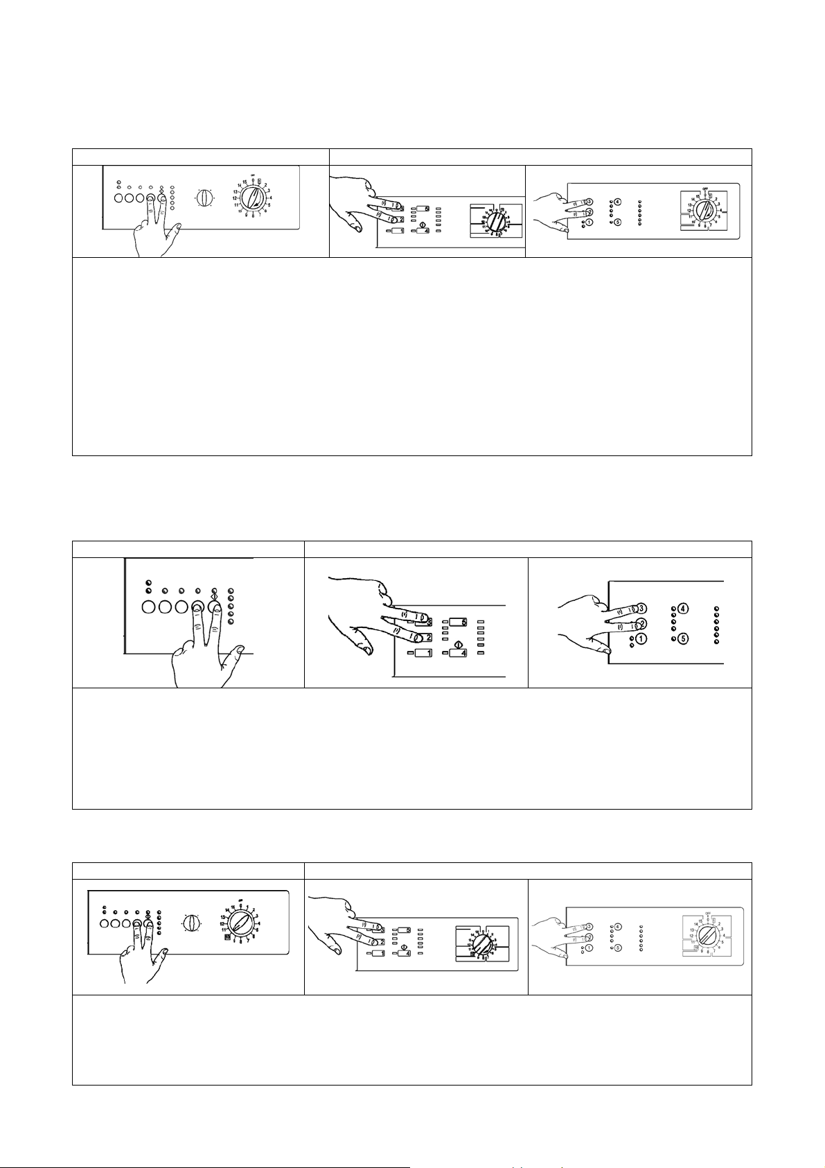
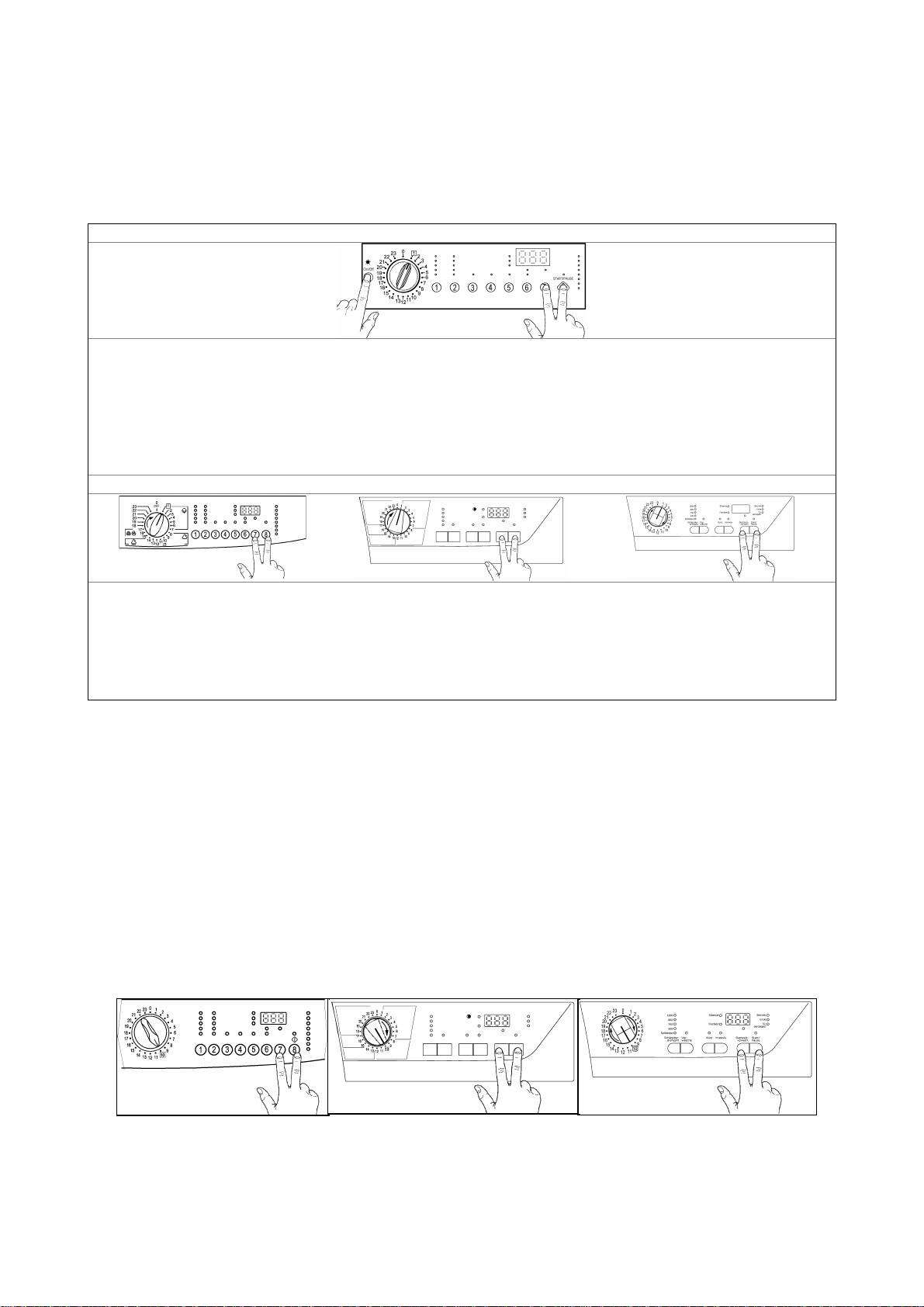
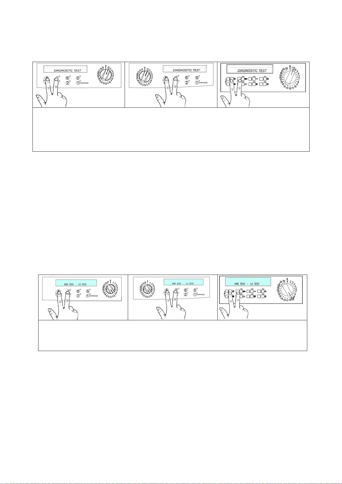
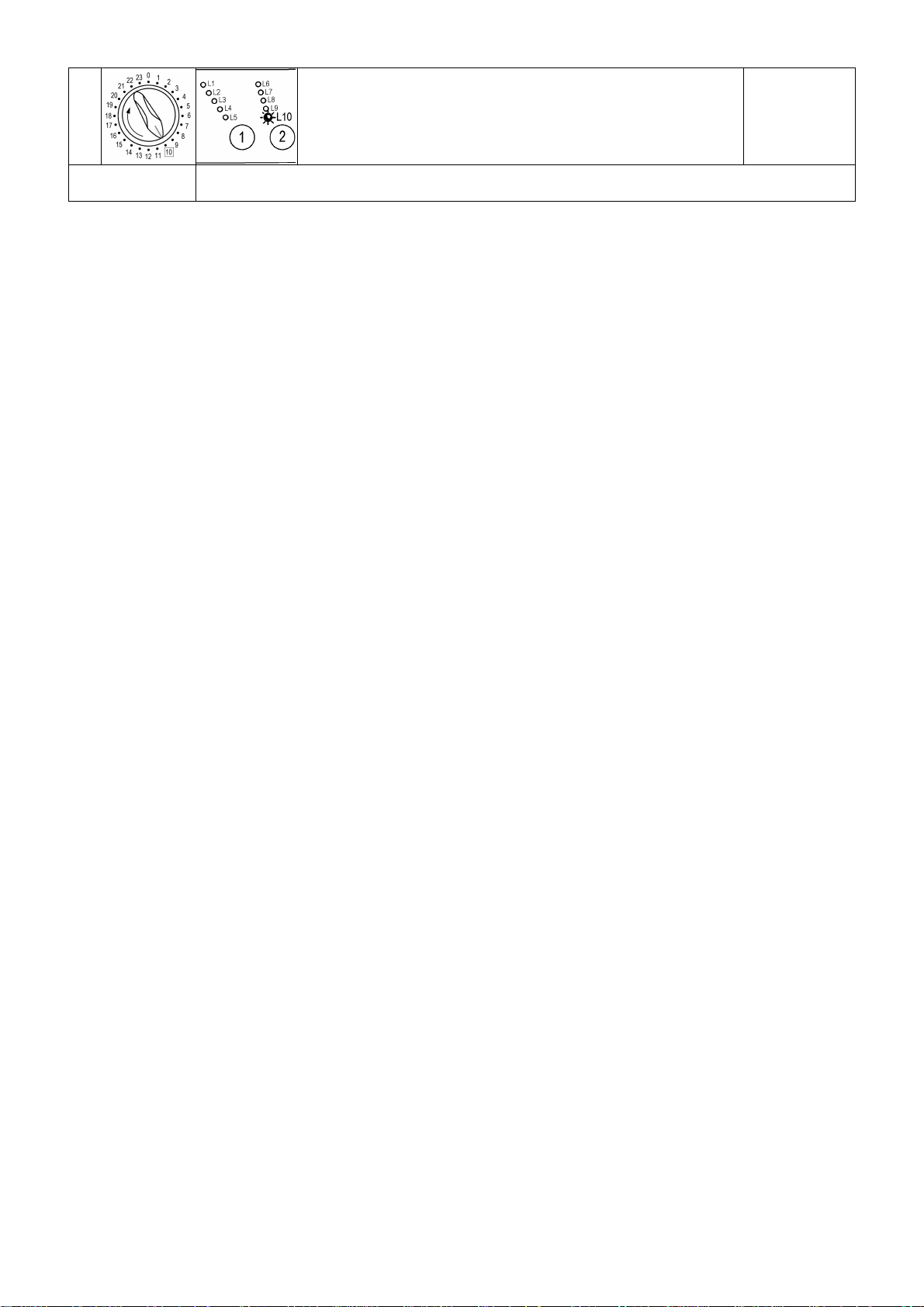
1.1 Access to the diagnostic cycle
versi on wit h horizont a l pus hbutto ns versi on wit h ve r t ic a l pus hbutto ns
1. Switch off the appliance.
2. Press and hold down the START/PAUSE button and any one of the OPTION buttons simultaneously.
horizontal version, while for vertical version pushbuttons are 2 and 3.
3. Holding down both buttons, switch the appliance on by turning the programme selector one posi tion
clockwise.
4. Continue to hold down the START/PAUSE button and the OPTION button horizontal ver si on, while for
vertic al v ersion pushbutt ons are 2 and 3, until the LEDs begin to flash (at least 2 seconds).
5. To exit the diagnostics system switch the applianc e off , on and t hen off again.
IMPORTANT: The position of the START/PAUSE button varies according to the model, and is
therefore not always the same.
1.2 Rapid reading of alarms
The last alarm can be di spl ay ed ev en if t he pr ogramme selector is not in the tenth posi tion (diagnostics) or if
the applianc e i s in normal oper ating mode (e.g. while the washing programme is in operation):
version wit h hori z ontal pushbuttons version wit h v ertic al pushbuttons
1. Press START/PAUSE and any one of the option buttons simultaneously for horizontal ver si on, while
for vertical version pushbuttons are 2 and 3, for at least two seconds: the LEDs first switch off, and then
display the flashing sequence corresponding to the alarm condition.
2. The alarm sequence continues as long as the two buttons are held down.
3. While the alarms are displayed, the current cycle being performed continues or, if the appliance is in the
programme sel ection phase, the options previ ousl y selected remain in memory.
1.3 Cancelling the last alarm
version wit h hori z ontal pushbuttons version wit h v ertic al pushbuttons
1. Access alarm reading mode (t enth sel ect or position)
2. Press and hold down START/PAUSE and any one of the option keys simultaneously for horizontal
version, while for vertical version pushbuttons are 2 and 3.
3. Hold the START/PAUSE and OPTION button down until the LEDs begin to flash (about 5 seconds)
Page 6
EWM1000
1.4 Phases of the diagnostics test
After accessing the diagnostics cycle, and irrespective of the type of control boar d fitted to the appliance
(i.e. vertical or horizontal buttons) and t he c onfiguration of the selector, turn the programme selec tor
clockwise to perform the diagnostics cycle for the various components and to read t he alarms.
All the alarm s are enabled during the diagnostics cycle.
Position of
selector
1
2
3
4
6
7
8
9
(*) In most cases, this time is sufficient to check the heating function. However, the time can be increased by repeating the heating
phase with out draini n g the water: p ass for a moment to a different ph as e of the diagnos t ic s c ycl e and then bac k t o th e h eati ng
check phase (if the temperature is higher than 80°C, heating does not take place).
Components activated Conditions of operation Function tested
- All the LEDs light in sequence
- When a button is pressed, the
corresponding LED l ights (and
the buzzer may sound)
- Door safety interlock
- Washing solenoid valve
- Door safety interlock
- Pre-wash solenoid valve
- Door safety interlock
- Washing and pr e- wash solenoid
valves
- Door safety interlock
- Wash solenoi d (if the water in
the tub is below 1st level)
- Heating element
- Door safety interlock
- Wash solenoi d (if the water in
the tub is below 1st level)
- Motor (55 rpm clockwise, 55
rpm anti-clock wise, impulse at
250 rpm)
- Door safety interlock
- Drain pump
- Motor up to 650 rpm then at
maximum spin speed
Only for top-loaders with drum
positioning system:
- Door safety interlock
- Motor (25 rpm)
- Drain pump
Always enabled
Door locked
Water level lower than antioverflow lev el
Maximum time 5 minutes
Door locked
Water level lower than antioverflow lev el
Maximum time 5 minutes
Door locked
Water level lower than antioverflow lev el
Maximum time 5 minutes
Door locked
Water leve l > 1st le ve l
Maximum time 10 minutes or
up to 90°C (*)
Door locked
Water leve l > 1st le ve l
Door locked
Water level lower then antiboiling level for spinning
Door locked
Water level lower then antiboiling level
Maximum time 2 minutes
Operation of the
user interfac e
Water ducted
through washing
compartment
Water ducted
through pre-wash
(bleach)
compartment
Water ducted
through conditioner
compartment
Heating
Check for leaks
from the tub
Drain and spin,
check for
congruence in
closure of pressure
switch levels
Test for positioning
of drum
QUICK GUIDE AND APPLIANCES LIST 6/176 599 72 40-80
Page 7
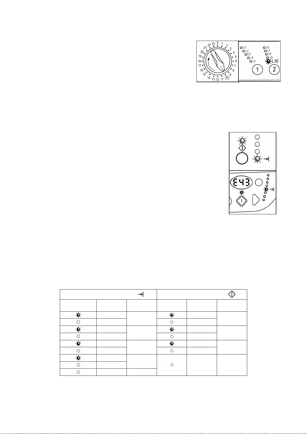
EWM1000
1.5 Reading the alarms
Proceed as follows to read the last alarm condition stored in the EEPROM on the
control boar d:
• Access diagnosti c s mode.
• Irrespective of the type of control board and confi gur ation, turn the programme
selector clockwise to the tenth position.
1.5.1 Di splaying the alarm
The alarm is displayed by a r epeated flashing sequence of the two LEDs (0.4
seconds ON, 0.4 seconds OFF, with a pause of 2.5 seconds between each
sequence). The buz z er (if featured) sounds a series of “beeps” in synchronization
with the flashing of the LEDs.
• END OF CYCLE indicator → indicates the first digit of the alarm code (family)
• START/PAUSE → indicates the second digit of the alarm code (number
within the family).
These two LEDs are present on all models (though confi gured in different
positions) and flash simultaneously.
Notes:
• The first letter of the alarm code “E” (Error) is not displayed si nc e it is the same for all alarm codes.
• The alarm code famili es are expressed in hexadecimal form. In other words:
→ A is repr es ented by 10 flashes
→ B is represented by 11 flashes
→ ...
→ F is represented by 15 flashes
• Configurati on er r or s are displayed by the flashing of all the LEDs (user i nterface not configured).
1.5.2 Examples of alarm display
Exam ple: Alarm E43 (problems with the door safety interlock tri ac ) will be displayed as follows:
• four flashes of t he E ND OF CYCLE LED indicat e the first digit E43;
• three flashes of t he STA RT/ P A USE LED i ndic ate the second digit E43;
END OF CYCLE LED
ON/OFF
Time
(seconds)
0.4
0.4
0.4
0.4
0.4
0.4
0.4
0.4
2.5 Pause
Value ON/OFF
1
2
3
4
START/PAUSE LED
Time
(seconds)
0.4
0.4
0.4
0.4
0.4
0.4
3,3 Pause
Value
1
2
3
1.5.3 Status of alarms during the diagnostics cycle
All the alarm s are enabled during the components diagnosti c s t est.
QUICK GUIDE AND APPLIANCES LIST 7/176 599 72 40-80
Page 8
EWM1000
1.6 Table of alarms codes EWM1000
Alarm Description Possible faul t Action/Machi ne status Reset
E00
Tap closed or water pressure insufficient; Drain hose
E11 Difficulty in filling during wash phase
E13 Water leakage
E21 Difficulties in dra ining
Drain pump triac faulty Drain pump faulty; Wiring faulty; Circuit board faulty. Safety drain - Cycle stopped, door open Selector on “0”
E23
Problems with «sensing» of drain pump triac Circuit board faulty. Safety drain – Cycle stopped, door released Selector on “0”
E24
Incongruence between contact closure of anti-
E33
boiling and 1st level of pressure switch
E35 Water ov e rflow
«sensing» circuit of anti-boiling pressure switch
E36
faulty
«sensing» circuit of 1st level faulty Circuit board faulty. Cycle blocked, door closed Selector on “0”
E37
HV «sensing» circuit of anti-flooding pressure
E39
switch faulty
Door open
E41
Problems with aperture of door
E42
Power triac on door interlock faulty
E43
Door interlock «sensing» faulty Circuit board faulty. Saf ety drain, door released Selector on “0”
E44
«sensing» on door interlock triac faulty Circuit board faulty. Saf ety drain, door released Selector on “0”
E45
Motor power triac short-circuited
E51
E52 No signal from motor tachimetric generator
«sensing» circuit on motor triac faulty Circuit board faulty. Cycle blocked Selector on “0”
E53
incorrectly positioned; Water fill solenoid faulty; Leaks from
pressure switch hydraulic circuit; Pressure switch faulty;
Wiring faulty; Circuit board faulty.
Drain hose incorrectly positioned; Water pressure
insufficient; Water fill solenoid faulty; Leaks or blockage in
pressure switch hydraulic circuit; Pressure switch faulty;
Circuit board faulty.
Drain hose kinked/blocked/incorrectly positioned; Drain filter
clogged or dirty; Drain pump faulty; Pressure switch faulty;
Wiring faulty; Circuit board faulty; Current leakage from
heating element to ground.
Pressure switch faulty; Current leakage from heating
element to ground; Heating element; Wiring faulty; Circuit
board faulty.
Water fill solenoid faulty; Leaks from pressure switch
hydraulic circuit; Pressure switch faulty; Wiring faulty; Circuit
board faulty.
Circuit board faulty. Cycle blocked, door closed Selector on “0”
Circuit board faulty. Cycle blocked, door closed Selector on “0”
Door safety interlock faulty; Wiring faulty;
Circuit board faulty.
Door safety interlock faulty; Wiring faulty;
Circuit board faulty
Door safety interlock faulty; Wiring faulty;
Circuit board faulty.
Circuit board faulty;
Current leakage from motor or wiring.
Motor faulty; Wiring faulty;
Circuit board faulty.
No alarm
Cycle paused, door closed Start
Cycle paused, door closed Start
Cycle paused Start
Safety drain - Cycle stopped, door open Selector on “0”
Cyc le block ed, do or closed. Safety dr ain.
Drain pump (sequence 5 min. ON - 5 min.
OFF)
Cycle paused Start
Cycle paused
Safety drain, door released Selector on “0”
Cyc le block ed, do or closed ( after 5 attempts in
diagnostics or immediate during selection)
Cyc le block ed, do or closed ( after 5 attempts in
diagnostics or immediate during selection)
Selector on “0”
Start or Selector
on “0”
Selector on “0”
Selector on “0”
QUICK GUIDE AND APPLIANCES LIST 8/176 599 72 40-80
Page 9
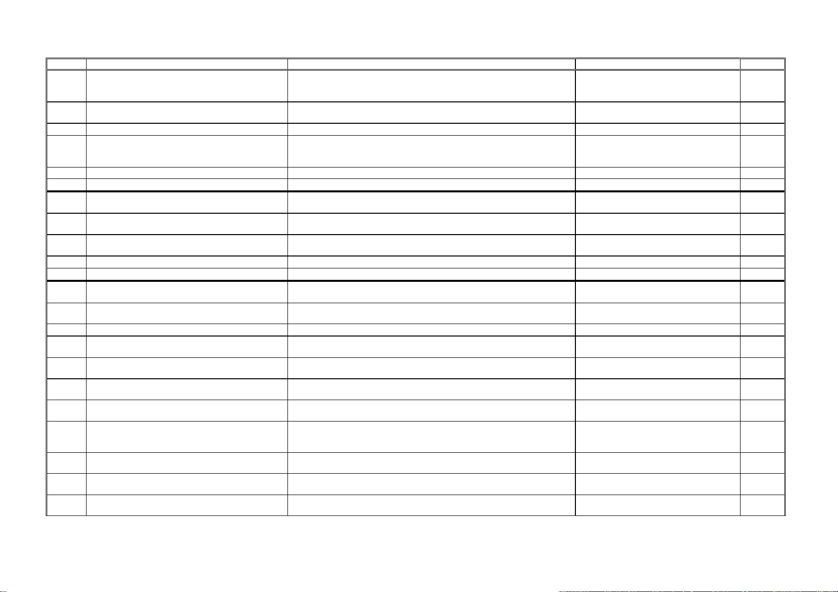
EWM1000
Alarm Description Possible faul t Action/Machi ne status Reset
Motor relay cont acts sticking
E54
Insufficient heating during washing
E61
Overheating during washing
E62
Power re lay for heating element faulty
E66
NTC washing sensor faulty
E71
Error in res et p o sit ion of selector Circuit board faulty. Cycle cancelled Selector on “0”
E82
Error in reading selector position Configuration data incorrect; Circuit board faulty.
E83
Incorrect machine configuration Configuration data incorrect; Circuit board faulty. Appliance blocked Selector on “0”
E93
Incorrect washing cycle configuration Configuration data incorrect; Circuit board faulty. Appliance blocked Selector on “0”
E94
Communications error between microprocesso r
E95
and EEPROM
Incongruence between hardware version and
E96
configuration.
Incongruence between programme selector and
E97
cycle configuration
Power supply frequency of appliance incorrect
EB1
Voltage too high
EB2
Voltage too low
EB3
Circuit board faulty;
Current leakage from motor or wiring.
NTC sensor faulty; Heating element faulty; Wiring faulty;
Circuit board faulty.
NTC sensor faulty; Heating element faulty; Wiring faulty;
Circuit board faulty.
Circuit boa rd faulty; Current leakage f r om hea t ing elem ent
or wiring to ground.
NTC sensor faulty; Wiring faulty;
Circuit board faulty.
Circuit board faulty. Appliance blocked Selector on “0”
Configuration data incorrect; Circuit board faulty. Appliance blocked Selector on “0”
Configuration data incorrect; Circuit board faulty. Appliance blocked Selector on “0”
Mains power supply problems (incorrect / interference);
Circuit board faulty.
Mains power supply problems (incorrect / interference);
Circuit board faulty.
Mains power supply problems (incorrect / interference);
Circuit board faulty.
Cyc le block ed, do or closed ( after 5 attempts in
diagnostics or immediate during selection)
Heating phase skipped --Safety drain (with co ol ing w ater f i ll) - Sto p with
door open
Safety drain (with co ol ing w ater f i ll) - Sto p with
door open
Heating phase skipped ---
During the cycle continues normally, switches
off completely during selection
Cycle blocked until normal power supply
conditions are restored
Cycle blocked until normal power supply
conditions are restored
Cycle blocked until normal power supply
conditions are restored
Selector on “0”
Selector on “0”
Selector on “0”
---
Selector on “0”
Selector on “0”
Selector on “0”
1.6.1 No t es concerning certain alarm codes
Configuration alarms E93-E96: If these alarm s are generated (when the appliance is switched on), operation of t he appliance is blocked and all the
LEDs light. The di agnostics procedure cannot be acc essed; t he only option is to switch the appliance OFF (by turning the selector to position “0”).
Configuration alarm E94: For this alarm code, only the family for alarm “9” is di spl ay ed; the diagnostics procedure cannot be ac c essed, and the “rapid
alarm display” function cannot be used.
Alarms EB1-EB2-EB3: In the event of problems with the mains power supply, the appliance remains in alarm mode until the mains fr equenc y or
voltage are r estor ed to the correct value or the appliance i s switched of f (by turning the programme selector to “0”). The family of alarm “B” i s di spl ay ed;
the diagnosti c s procedur e c annot be accessed, and the “rapid alarm display” function cannot be used. The complete alarm code can be read only when
the abnormal situation has ceased.
Alarms E51- E52: During the diagnostics test, all the alarms are displayed. Norm ally , when the programme selector is turned f rom one test phase to
another, the appliance exits the alarm condition and performs the phase selected. This does not take place in the case of alarm s E51 (power triac on
motor short-circuited) and E52 (no signal f r om t he tachymetric generator on the motor): in these cases, the only option to exit the alarm condition is to
switch the appliance OFF by turning the selector t o position “0” (reset).
QUICK GUIDE AND APPLIANCES LIST 9/176 599 72 40-80
Page 10
EWM1000
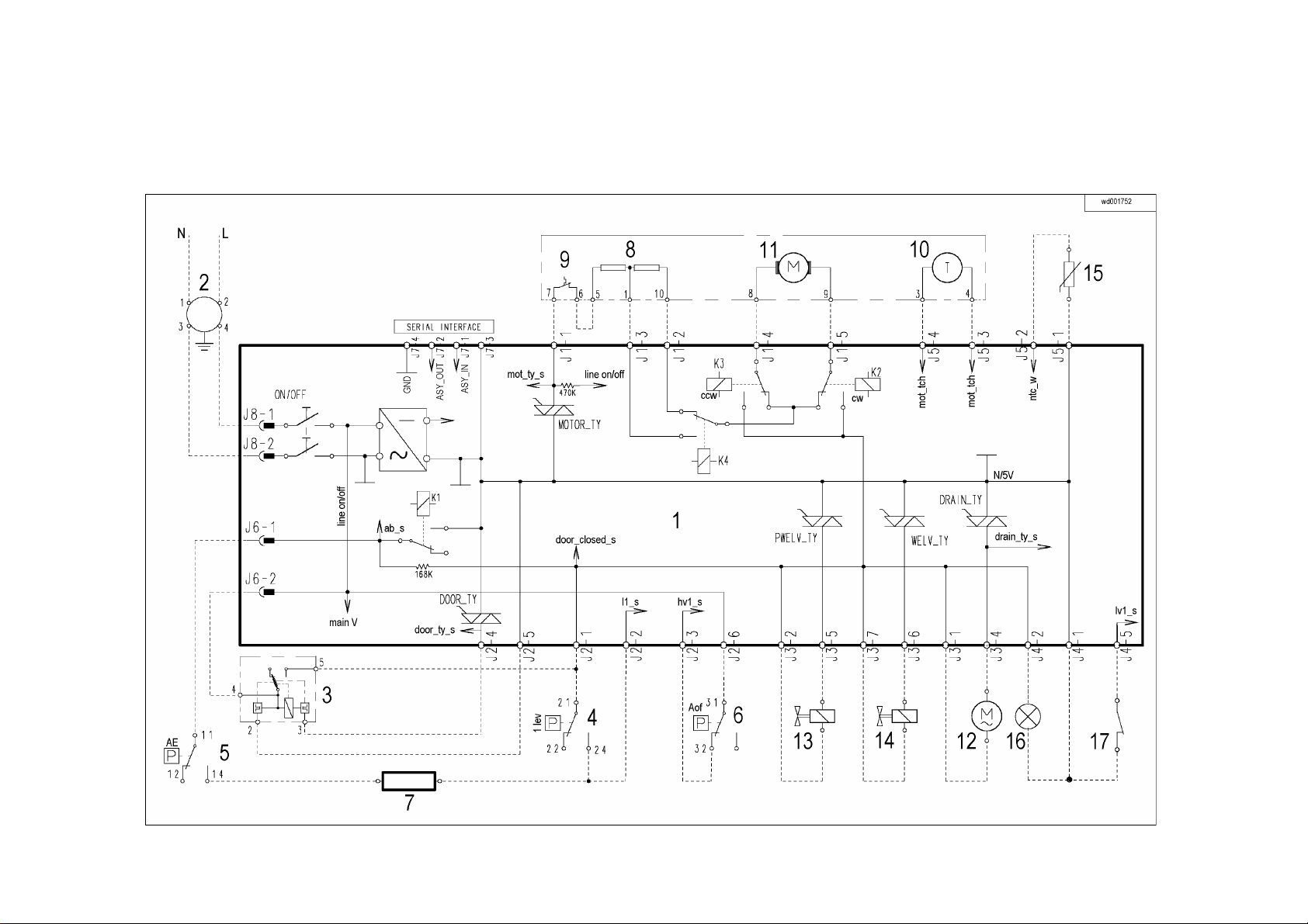
1.7 Elementary diagram
1.7.1 With instantaneous door locking device
QUICK GUIDE AND APPLIANCES LIST 10/176 599 72 40-80
Page 11
EWM1000
1.8 With PTC door locking device
QUICK GUIDE AND APPLIANCES LIST 11/176 599 72 40-80
Page 12

EWM1000
1.8.1 Key t o circuit diagram
Electrical compo nents – appliance Components of elect ron ic circuit board
1. Circuit board
2. Suppressor
3. Main switch (on progr amme selector)
4. Door safety interlock
5. 1st level pressure swit c h
6. Anti-boiling pressure switch
7. Anti-ov erflow pressure switch (certain models only)
8. Heating element
9. Stator (motor)
10. Overl oad circuit- breaker (m otor)
11. Tachymetric generator (motor)
12. Rotor (motor)
13. Drain pump
14. Pre-wash solenoid valve
15. Washing solenoid valve
16. “ Door c losed” lamp (certain m odels onl y )
17. Dr um posi tioning system (DSP) (top- loaders – certain models only )
DOOR_TY Triac for door saf ety interlock
DRAIN_TY Triac for drai n pum p
K1 Heating elem ent r elay
K2 Motor relay: clockwise rotation
K3 Motor relay: anti-clockwise rotation
K4 Motor relay: half-range power (certain models only)
MOTOR_TY Motor triac
ON/OFF Main switch (programme selector)
PWELW_TY Tri ac for pre-wash solenoid valve
Serial interface Asynchronous serial interface
WELV_TY Triac for washing solenoid v alv e
QUICK GUIDE AND APPLIANCES LIST 12/176 599 72 40-80
Page 13
EWM1000
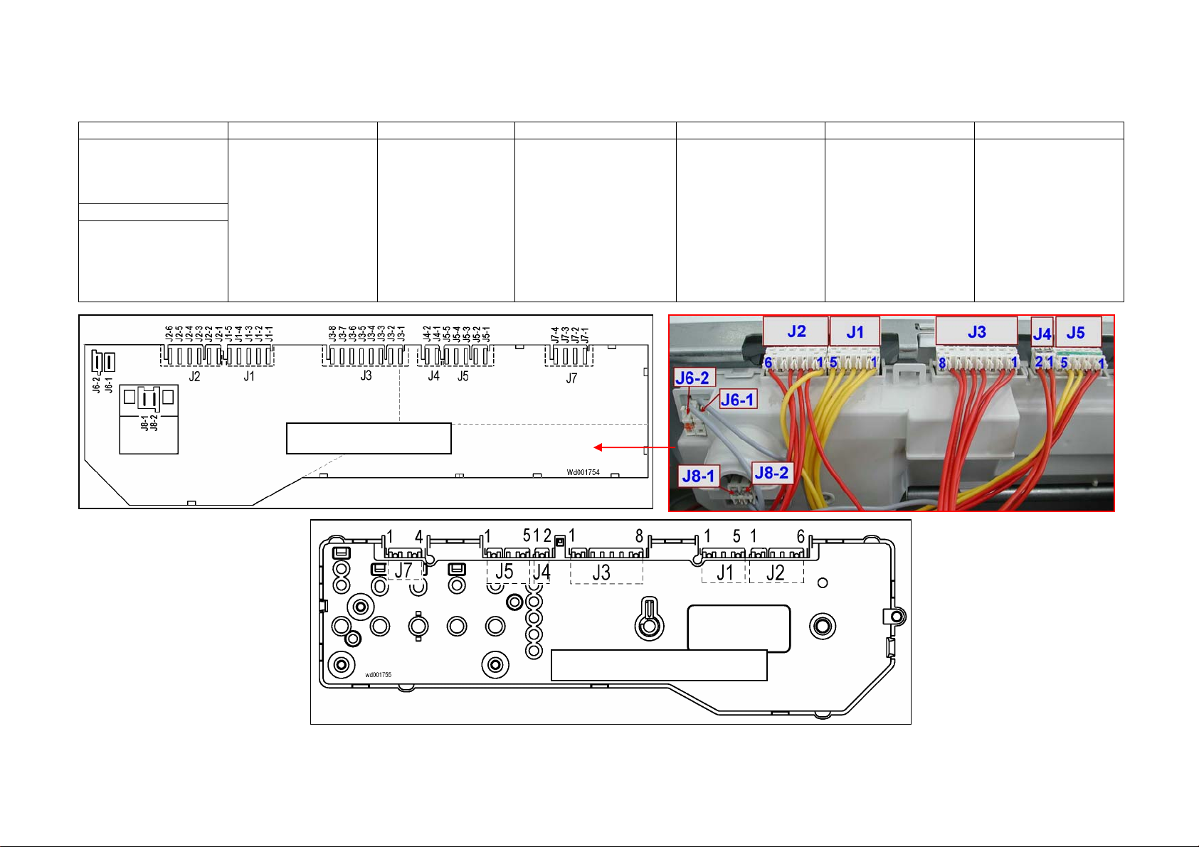
1.9 Connectors on circuit board EWM1000
J6 J2 J1 J3 J4 J5 J7
J6-1: Heati ng element
(relay)
J6-2: Door safety
int erl o ck (line)
J8
J8-1 line
J8-2 line (neutral)
J2-1 Door safety interlock
(line-sensing)
J2-2 1st level(sensing)
J2-3 (Anti-overflow
pressure switch)
J2-4 Door safety interlock
(triac)
J2-5 (Door safety
interlock)
J2-6 (Anti-overflow
pressure switch)
Rear view
J1-1 Motor (triac)
J1-2 Motor (stator – full
range)
J1-3 Motor (stator - 1/2
range)
J1-4 Motor (rotor)
J1-5 Motor (rotor)
J3-1 Drain pump (line)
J3-2 Solenoids (line)
J3-3 (line)
J3-4 Drain pump (triac)
J3-5 Pre-wash solenoid
(triac)
J3-6 Washing solenoid
(triac)
J3-7 Solenoids (line)
J3-8 (Not used)
Front view
J4-1 “Door closed” pilot
lamp
J4-2 “Door closed” pilot
lamp
J5-1 NTC temperature
sensor
J5-2 NTC temperature
sensor
J5-3 Motor (tachymetric
generator)
J5-4 Motor (tachymetric
generator)
J5-5 (DSP drum
positioning syste m)
Serial interface:
J7-1 ASY_IN
J7-2 ASY_OUT
J7-3 5V
J7-4 GND
QUICK GUIDE AND APPLIANCES LIST 13/176 599 72 40-80
Page 14
EWM1000
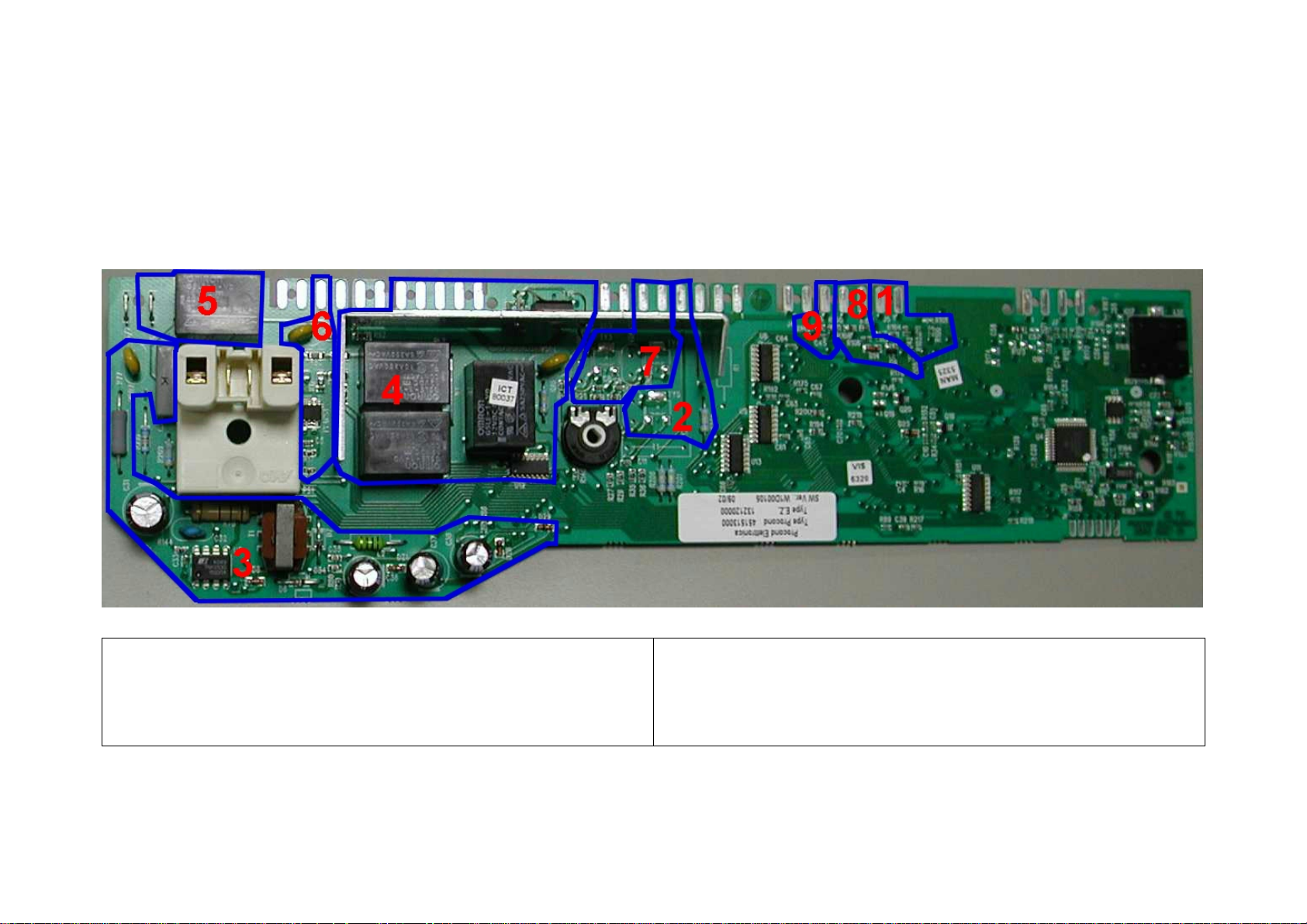
1.10 Burning on the circuit board EWM1000
1.10.1 EWM1000
In case of burning on the main ci r c uit board, check that the problem is not caused by another electrical component (short-circuits, poor insulation, water leakage).
Refer to the figures bel ow in or der to identify the component that mi ght have caused the burning according t o the posi tion of the burned area.
The circuit boar d s hown below is the version with the greatest number of components: other boards may not feature all t hes e c om ponents (relay K4 and buzzer).
1.10.2 Components side (common)
1. NTC washing temperature sensor
2. Drain pump
3. Power supply
4. Motor
5. Heating element
6. Door safety interlock
7. Water fill solenoids
8. Tachymetri c generat or (motor)
9. Drum positi oning system (top-loaders)
QUICK GUIDE AND APPLIANCES LIST 14/176 599 72 40-80
Page 15
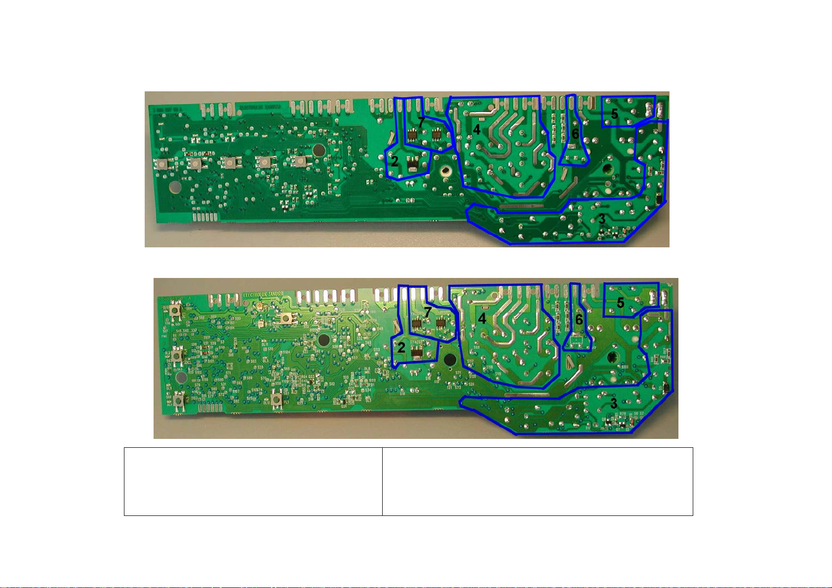
EWM1000
1.10.3 Pushbutton – led side (horizontal buttons)
1.10.4 Pushbutton – led side (vertical bu tton s)
1. ---
2. Drain pump
3. Power supply
4. Motor
5. Heating element
6. Door safety interlock
7. Water fill solenoids
8. Tachymetri c generat or (motor)
9. Drum positi oning system (top-loaders)
QUICK GUIDE AND APPLIANCES LIST 15/176 599 72 40-80
Page 16
EWM1000plus EWM2000evo EWM3000new
2 EWM1000plus 2000evo 3000new
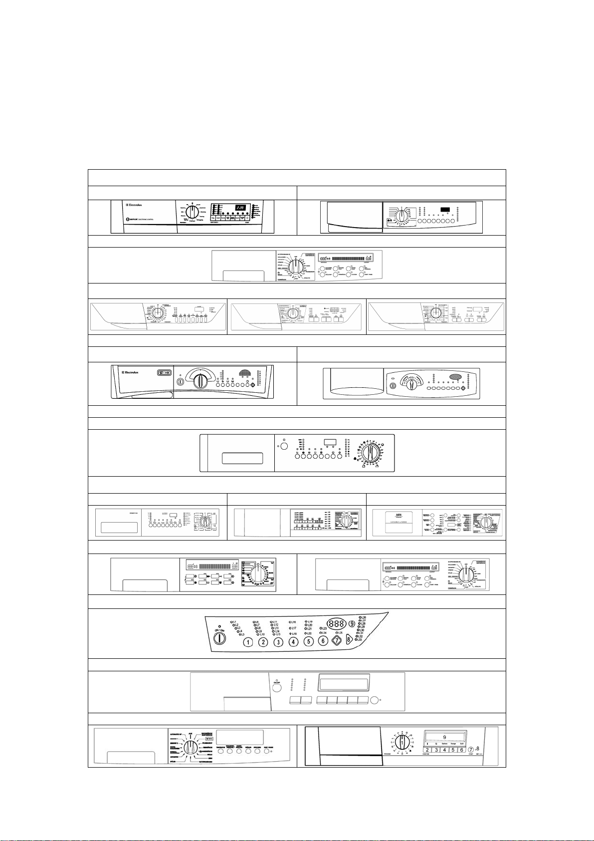
2.1 Control panel
The configurat ion of the control panel depends on the fol lowing:
ª Type of control/ display board (with or without display)
ª Design of the cont r ol panel and posi tion of the programme selector ( ri ght or left of the buttons)
ª Number and confi gur ation of the buttons (max. 8)
ª ON/OFF switch: inc or por ated in the programme select or or wit h separated button
Version with lef t select or and incorporated ON/OFF button
Alpha-Rim Sigma
Club Display
Delta
Version with left selector and button ON/OFF switch
Alpha Ellipse
Version with righ t select or and button ON/OFF switch
Version with righ t select or and incorporated ON/OFF switch
Sigma/ZK AEG NexXxt AEG NE W
Delta Version without selector and button ON/OFF switch
Multipanel Built-in
Club Display
LCD Version without selector and button ON/OFF switch
LCD Version with left selector and incorporated ON/OFF button
QUICK GUIDE AND APPLIANCES LIST 16/176 599 72 40-80
Page 17
EWM1000plus EWM2000evo EWM3000new
2.2 Sigma/Alpha/Ellipse//Multipanel Built-In/Sigma-ZK/Jewel with or without
selector
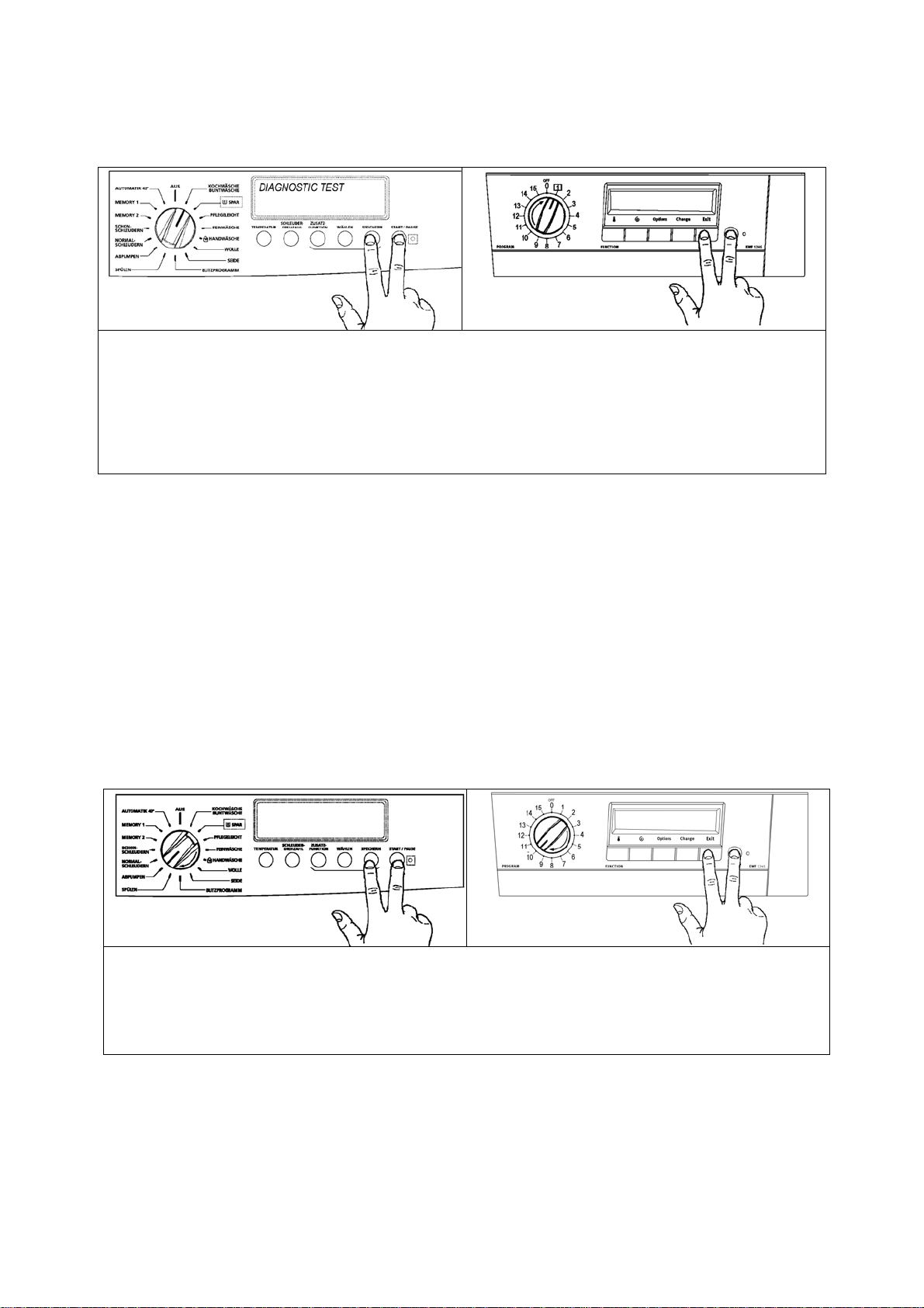
2.2.1 Access to diagnosti cs system
Attention: the pr ogr am m e select or is not always in the position indicated in the picture; it can be on the right
or on the left of the display boar d!
Version with selector and button ON/OFF switch
1. Cancel the set progr amme and switch the appliance off.
2. Rotate the progr amme selector of one pos itions clockwise.
3. Press the start/pause (8) button and any of t he option button simultaneously and then, keeping them
pressed, swi t ch the appliance on through the ON/OFF button (on/off).
4. Hold the start/pause and option buttons down till the LEDs start f lashing (about 5 seconds).
5. To exit the diagnostics system switch the applianc e off, on and then off again.
Version with select or and incorporated ON/OFF switch
1. Cancel the set progr amme switching the appliance off .
2. Press the start/pause (8) button and any of the option buttons simult aneousl y and then, keeping them
pressed, swi t ch the appliance on rotating the pr ogr amme selector of one position clockwise.
3. Hold the start/pause and option buttons down till the LEDs start f lashing (about 5 seconds).
4. To exit the diagnostics system switch the applianc e off, on and then off again.
2.2.2 Rap id reading of alarm codes
The last alarm code can be displayed even if the programm e selector is not in the tenth position
(diagnostic s) or if the appliance is in normal operating mode (e.g. during the ex ec ution of the washing
programme):
ª Press and hold down START/PAUSE and the option button nearest to the START/PAUSE button for at
least two seconds: the LEDs initially switch off, and then display the flashing sequence cor responding to
the alarm; if the displ ay is featured, it will display the alarm c ode
ª The alarm sequence is displ ay ed for the time in which the buttons are hold down
ª During the time t he alarm is displayed, the applianc e conti nues to perform the cycle or, if it is in the
selection phase, it keeps in memory the options previously chosen.
2.2.3 Can celling the last alarm
It is good practice to cancel the last alarm, after readi ng the alarm code to check whether the alarm r e- occurs
during the diagnostics control after the r epar ation of the appliance.
1. Select diagnostics mode and turn the programme sel ector to the tenth position (reading of alarm)
2. Press and hold down START/PAUSE and any of the option buttons at the same time for five
seconds.
QUICK GUIDE AND APPLIANCES LIST 17/176 599 72 40-80
Page 18
EWM1000plus EWM2000evo EWM3000new
2.3 AEG NexXxt Version with selector and incorporated ON/OFF switch
2.3.1 Access to diagnosti cs system
1. Cancel the set progr amme and switch the appliance off.
2. Press buttons 1 and 5 (or butt on 2 and 6) simult aneous ly and then, holding them down, swit c h
the applianc e on by rotating the programme selector of one position cl oc k wis e.
3. To exit the diagnostics system switch the applianc e off, on and then off again.
2.3.2 Rap id reading of alarm codes
The last alarm code can be displayed even if the programm e selector is not in the tenth position
(diagnostic s) or if the appliance is in normal operating mode (e.g. during the ex ec ution of the washing
programme):
ª Press buttons 1 and 5 simultaneously f or at least 2 seconds: the LED switch off and then di spl ay the
sequence of flashes indicating the alarm.
ª The alarm sequence is displ ay ed for the time in which the buttons are hold down
ª During the time t he alarm is displayed, the applianc e conti nues to perform the cycle or, if it is in the
selection phase, it keeps in memory the options previously chosen.
2.3.3 Can celling the last alarm
It is good practice to cancel the last alarm, after readi ng the alarm code to check whether the alarm r eoccurs during the diagnostics control aft er the reparation of the appliance
1. Select diagnostics mode and turn the programme sel ector to the tenth position (reading of
alarm)
2. Press buttons 1 and 5 simultaneously.
3. Hold buttons 1 and 5 down (about 2 seconds).
QUICK GUIDE AND APPLIANCES LIST 18/176 599 72 40-80
Page 19
EWM1000plus EWM2000evo EWM3000new
2.4 AEG New Version with right selector and incorporated ON/OFF switch
2.4.1 Access to diagnosti cs system
1. Cancel the set progr amme and switch the appliance off.
2. Press buttons 1 and 2 simultaneously and then, holding them down, swit c h the appliance on
by rotating t he pr ogr amme selector of one position clockwise.
3. To exit the diagnostics system switch the applianc e off, on and then off again.
2.4.2 Rap id reading of alarm codes
The last alarm code can be displayed even if the programm e selector is not in the tenth position
(diagnostic s) or if the appliance is in normal operating mode (e.g. during the ex ec ution of the washing
programme):
ª Press buttons 1 and 2 sim ultaneously for at least 2 seconds: the LED s witch off and then display the
sequence of flashes indicating the alarm.
ª The alarm sequence is displ ay ed for the time in which the buttons are hold down
ª During the time t he alarm is displayed, the applianc e conti nues to perform the cycle or, if it is in the
selection phase, it keeps in memory the options previously chosen.
2.4.3 Can celling the last alarm
It is good practice to cancel the last alarm, after readi ng the alarm code to check whether the alarm r eoccurs during the diagnostics control aft er the r epar ation of the applianc e
1. Select diagnostics mode and turn the programme sel ector to the tenth position (reading of
alarm)
2. Press buttons 1 and 2 simultaneously.
3. Hold buttons 1 and 2 down (about 2 seconds).
QUICK GUIDE AND APPLIANCES LIST 19/176 599 72 40-80
Page 20
EWM1000plus EWM2000evo EWM3000new
2.5 DELTA Version without selector and button ON/OFF switch
2.5.1 Access to diagnosti cs system
1. Reset the set programme with the SKIP/RESET button and then switch the appliance off.
2. Press the START/PAUSE and SKIP/RESET buttons simultaneously and then, hol ding the
buttons down, switc h the appliance on using the ON/OFF button.
3. Hold the buttons down until the buzzer sounds and the LEDs start flashing (about 4 seconds).
4. To exit the diagnostics system switch the applianc e off , on and t hen off again.
2.5.2 Rap id reading of alarm codes
The last alarm code can be displayed even if the programm e selector is not in the tenth position
(diagnostic s) or if the appliance is in normal operating mode (e.g. during the ex ec ution of the washing
programme):
ª Press START/PAUSE and SKIP/RESET buttons simultaneously f or at least 2 seconds: the LE Ds s witch
off and then display the sequence of flashes indicati ng the alarm.
ª The alarm sequence is displ ay ed for the time in which the buttons are hold down
ª During the time t he alarm is displayed, the appli ance continues to perf orm the cycle or, if it is i n the
selection phase, it keeps the options previously c hosen in memory.
2.5.3 Can celling the last alarm
It is good practice to cancel the last alarm, after readi ng the alarm code to check whether the alarm r eoccurs during the diagnostics control aft er the reparation of the appliance
1. Select diagnostics mode and Press the Fabric s (1) or Temperature (2) button until LED L10
lights (readi ng of alarm).
2. Press and hold down START/PAUSE and START/RESET.
QUICK GUIDE AND APPLIANCES LIST 20/176 599 72 40-80
Page 21
EWM1000plus EWM2000evo EWM3000new
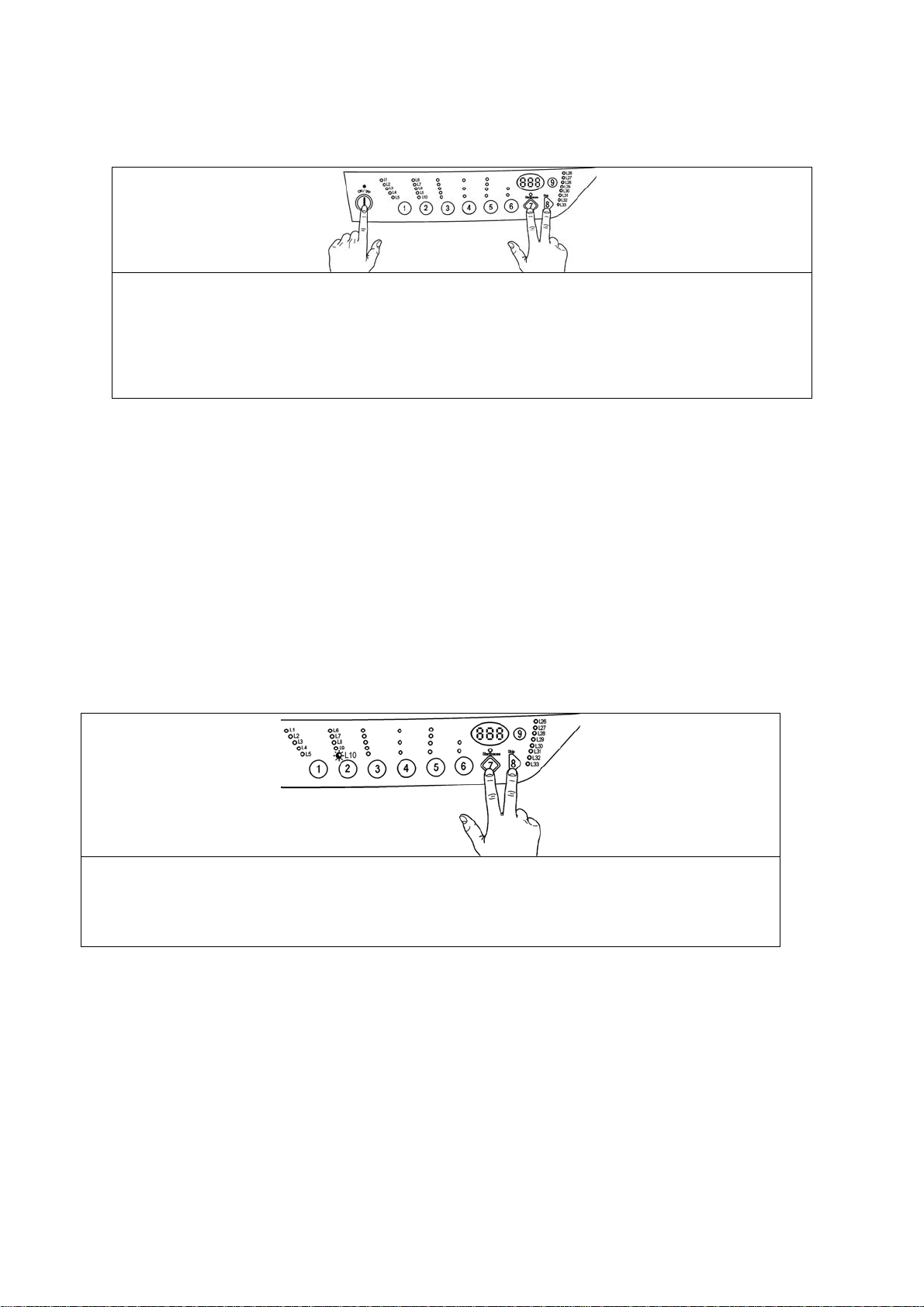
2.6 CLUB DISPLAY Version with selector and incorporated ON/OFF switch
2.6.1 Access to diagnosti cs system
1. Cancel the set progr amme and switch the appliance off.
2. Press buttons 8 and 7 simult aneousl y , then, holding them down, switc h the appliance on rotating t he
programme sel ector of one position c loc kwise.
3. Hold the buttons down up to DI AGNOSTIC MODE appears (about 5 seconds).
4. To exit the diagnostics system switch the applianc e off, on and then off again.
2.6.2 Rap id reading of alarm codes
The last alarm code can be displayed even if the programm e selector is not in the tenth position
(diagnostic s) or if the appliance is in normal operating mode (e.g. during the ex ec ution of the washing
programme):
ª Five minutes aft er the switching on, press and hold down the 8 and 7 butt ons simultaneously for 2
seconds, the LCD displ ay shows the l ast alarm codes (of the main board and displ ay boar d) . The
displayi ng of t he alarms depends on the time in which the buttons are hol d down.
ª During the time t he alarm is displayed, the applianc e conti nues to perform the cycle or, if it is in the
selection phase, it keeps in memory the options previously chosen.
2.6.3 Can celling the last alarm
It is good practice to cancel the last alarm, after readi ng the alarm code to check whether the alarm r eoccurs during the diagnostics control aft er the reparation of the appliance
1. Select diagnostics mode and turn the programme sel ector to the tenth position (reading of alarm)
2. Press simultaneously buttons 8 and 7.
3. Hold them down until the alarms are cancelled.
QUICK GUIDE AND APPLIANCES LIST 21/176 599 72 40-80
Page 22
EWM1000plus EWM2000evo EWM3000new
2.7 LCD Version without selector and button ON/OFF switch
2.7.1 Access to diagnosti cs system
1. Reset the set programme and switch the appliance off.
2. Press the 10 and 11 buttons, simultaneously, then, holding them down, switch the appliance on with
ON/OFF button.
3. Hold the buttons down till DIAGNOSTIC MODE appears (about 5 seconds).
4. To exit the diagnostic system switch the appli ance off, on and then off again.
2.7.2 Rap id reading of alarm codes
The last alarm code can be displayed even if the programm e selector is not in the tenth position
(diagnostic s) or if the appliance is in normal operating mode (e.g. during the ex ec ution of the washing
programme):
ª Five minutes aft er the switching on, press and hold down the 10 and 11 buttons simultaneously for 2
seconds, the LCD displ ay shows the l ast alarm codes (of the main board and displ ay boar d) . The
displayi ng of t he alarms depends on the time in which the buttons are hol d down.
ª During the time t he alarm is displayed, the applianc e conti nues to perform the cycle or, if it is in the
selection phase, it keeps in memory the options previously chosen.
2.7.3 Can celling the last alarm
It is good practice to cancel the last alarm, after readi ng the alarm code to check whether the alarm r eoccurs during the diagnostics control aft er the r epar ation of the applianc e
1. Select diagnostic mode and with button 4 go to tenth position (alarm reading)
2. Press simultaneously buttons 10 and 11.
3. Hold them down until the alarms are cancelled.
QUICK GUIDE AND APPLIANCES LIST 22/176 599 72 40-80
Page 23
EWM1000plus EWM2000evo EWM3000new
2.8 LCD Version with selector and button ON/OFF switch
2.8.1 Access to diagnosti cs system
1. Cancel the set progr amme and switch the appliance off.
2. Press the start/pause and exit buttons simultaneousl y , t hen, holding them down, switch t he
appliance on rotating the programme selector of one position clockwise.
3. Hold the START/PAUSE and EXIT buttons down up to DIAGNOSTIC MODE appears (about 5
seconds).
4. To exit the diagnostic system switch the appli ance off, on and then off again.
2.8.2 Rap id reading of alarm codes
The last alarm code can be displayed even if the programm e selector is not in the tenth position
(diagnostic s) or if the appliance is in normal operating mode (e.g. during the ex ec ution of the washing
programme):
ª Five minutes aft er the switching on, press and hold down the START/PAUSE and EXIT buttons for 2
seconds, the LCD displ ay ing shows the last alarm codes (of the main boar d and display board). The
displayi ng of t he alarms depends on the time in which the buttons are hol d down.
ª During the time t he alarm is displayed, the applianc e conti nues to perform the cycle or, if it is in the
selection phase, it keeps in memory the options previously chosen.
2.8.3 Can celling the last alarm
It is good practice to cancel the last alarm, after readi ng the alarm code to check whether the alarm r eoccurs during the diagnostics control aft er the reparation of the appliance
1. Select diagnostics mode and turn the programme sel ector to the tenth position (reading of alarm)
2. Press simultaneously START/PAUSE button and button EXIT (nearest option to START/PAUSE
button).
3. Hold down the START/PAUSE and EXIT button until the alarms are c anc elled.
QUICK GUIDE AND APPLIANCES LIST 23/176 599 72 40-80
Page 24
EWM1000plus EWM2000evo EWM3000new
2.9 Phases of the diagnostics test
Independently of the type of selector, after activating the diagnostics system, the operation diagnostics of
the different components and the reading of the alarm s can be performed, by rotating the sel ec tor
clockwise.
In models with digit the code of the selector position is display ed for a second.
In the diagnostics cycle all alarms are activated. If duri ng the cycle operati on an alarm occurs, the appliance
blocks and the LEDs (and the display) flash indic ating the relative code.
Diagnostics phases
Selector
1
2
3
4
5
6
7
8
9
Only
pushbutton
Components actioned Operating conditions Function checked
All the LEDs light in
sequence. When a
button is pressed, the
corresponding LED
lights (and the buzz er , if
featured, sounds)
Door interloc k Washing
solenoid
Door interloc k Pre-wash
solenoid
Door interloc k
Pre-wash and wash
solenoids
Door interloc k .
Bleach/stains solenoid.
Door interloc k
Washing solenoid if the
level of water in the tub is
below 1st level Heating
element.
Door interloc k . (Washing
solenoid if the l ev el of
water in the tub is bel ow
1st level). Motor (55 rpm
clockwise, 55 rpm
counter-clockwise, 250
rpm impulse)
Always activated
Door locked
Water level below
anti-flooding level
Maximum time 5
minutes
Door locked
Water level below
anti-flooding level
Maximum time 5
minutes
Door locked
Water level below
anti-flooding level
Maximum time 5
minutes
Door locked
Water level below
anti-flooding level
Maximum time 5
minutes
Door locked.
Water at 1st level.
Maximum time 10
min. or up to 90ºC. (*)
Door locked
Water level at 1st
level.
Operation of
the user
interface
Water ducted
through
washing
compartment
Water ducted
through prewash
compartment
(bleach)
Water ducted
through
conditioner
compartment
Water ducted
through
bleach/stains
compartment
Heating
Check for leaks
from the tub
Drain and
Door interloc k
Drain pump Motor up to
650 rpm then at
maximum spin speed
Drying heater
Fan
Condensation solenoid
Drain pump
Motor
Door locked
Water leve l lowe r
than anti-boi ling
level for spinning
Door closed Drying
spin; control
of congruence
in closure of
level pressure
switches
Displayed
parameters (1 )
Button
codification
(**)Selection
position code
(**)Selection
position code
(**)Selection
position code
(**)Selection
position code
(**)Selection
position code
(**)Selection
position code
(**)Selection
position code
(**) selector
position code
QUICK GUIDE AND APPLIANCES LIST 24/176 599 72 40-80
Page 25
EWM1000plus EWM2000evo EWM3000new
10
11, 12 ...24
(*)In most cases, this time is sufficient to c heck the heating. However, the time c an be inc r eased by
repeating the phase wit hout draining the water: for a moment t o a diff er ent phase of the diagnostics cycle
and then back to the heating c ontrol phase (if the temperature i s higher than 80°C, heating does not take
place).
(**) See tables of following pages.
(1) Model s with Display.
All LEDs light i n sequence. Pres si ng a button the corresponding LED lights (and the Buzzer
sounds, if featur ed)
Reading/cancelling last alarm Alarm code
QUICK GUIDE AND APPLIANCES LIST 25/176 599 72 40-80
Page 26
EWM1000plus EWM2000evo EWM3000new
2.10 Reading the alarm codes
In order to read the last alarm code memorized in the EEPROM on the
PCB:
with knob
• Enter diagnostics mode
• Irrespective of the type of PCB and configurati on, t urn the
programme sel ector clockwise to the tenth position.
without knob
• Press the Fabrics (1) or Temper ature (2) button until LED L10
lights.
2.10.1 Displaying the alarm
The alarm is displayed by a r epeated flashing sequence of the two LEDs (0.4
seconds lit, 0.4 seconds off, with an interval of 2.5 seconds between sequences).
The buzzer (if featured) will sound “bips” in synchronization with the flashing of
the LEDs.
• END OF CYCLE LED → indicates the first digit of the alarm code (family)
• START/PAUSE → indicates the second digit of the alarm code (number
within the family)
These two LEDs are featured on all models (though they are configured
differently), and flash simultaneously.
Notes:
• The first letter of the alarm code “E” (Error) is not displayed, since this letter is
common to all alarm codes.
• The alarm code “f amili es” are sho wn in hexadecimal; in other words:
→ A is represented by 10 fl ashes
→ B is represented by 11 fl ashes
→ ...
→ F is represented by 15 flashes
• Configurati on er r or s are shown by the flashing of a series of LEDs.
2.10.2 Examples of alarm displays
Example: Alarm E43 will displ ay the following:
• On the display, if featured, E43
• The sequence of four flashes of the End-of-cycle LED indicates the first number E
• The sequence of three flashes of the Start/Pause LED indicates the second number E4
END-OF-CYCLE LED
On/Off
Time
(Sec.)
0.4
0.4
0.4
0.4
0.4
0.4
0.4
0.4
2.5 Pause
Value On/Off
1
2
3
4
START/PAUSE LED
Time
(Sec.)
0.4
0.4
0.4
0.4
0.4
0.4
3,3 Pause
43;
Value
1
2
3
3;
QUICK GUIDE AND APPLIANCES LIST 26/176 599 72 40-80
Page 27
EWM1000plus EWM2000evo EWM3000new
2.11 Table of alarms codes EWM 1000plus EWM2000EVO EWM3000NEW
Alarm Description Possible malfunction Action/status of machine Reset
E00
Tap closed or water pressure too low; Drain tube improperly positioned;
E11 Poor water fill before wash cycle
Difficulty in water fill during drying (maximum
E12
time 3 min. water fill in drying during the wash
load unrolling phase)
E13 Water leaks
E21 Poor draining
Difficulty in water fill during drying or drying
E22
condenser clogged (anti-boiling pressure
switch closed on “FULL”)
Defective triac for drain pump Drain pump defective; Wiring defective; Main board defective.
E23
Malfunction in sensing circuit on triac for drain
E24
pump
Malfunction in pressure switch circuit
E31
(frequency of signal from pressure switch out
of limits)
Electronic pressure switch improperly
calibrated (level on electronic pressure switch
differs from 0-66 mm after initial calibration
E32
drain and when antiboiling pressure switch is
on “empty”).
Inconsistency between level on electronic
pressure switch and level on antiboiling
E33
pressure switch 1-2 (fault persists for at least
60 sec.).
Inconsistency between level on electronic
pressure switch and level on antiboiling
E34
pressure switch 2 (fault persists for at least 60
sec.).
Water fill solenoid valve is defective; Leaks from water circuit on
pressure switch; Pressure switch defective; Wiring defective; Main board
defective.
Tap closed or water pressure too low; solenoid valve; pressure switch
water circuit; pressure switches; wiring; main board.
Drain tube improperly positioned; Water pressure too low;
Water fill solenoid valve is defective; Water circuit on pressure switch is
leaking/clogged; Pressure switch defective.
Drain tube kinked/clogged/improperly positioned; Drain filter
clogged/dirty; Drain pump defective; Pressure switch defective; Wiring
defective; Main board defective; Electrical current leak between heating
element and ground.
Drain hose kinked; filter clogged: drying condenser clogged; drain pump
faulty; pressure switches faulty; wiring; main circuit board defective;
current leakage between heater and ground.
Main board defective.
Pressure switch; Wiring; Main board; Cycle stops with door locked OFF/reset
Tap is closed or water pressure is too low;
Solenoid valve;
Water circuit on pressure switches; pressure switches;
Wiring; main board;
Pressure switch defective;
Electrical current leak between heating element and ground; Heating
element; Wiring defective;
Main board defective.
Water circuit;
Pressure switch defective;
Electrical current leak between heating element and ground; Heating
element; Wiring defective;
Main board defective.
Water circuit;
No alarm ---
Cycle is paused with door locked Start
Cyc le is paused Start
Cycle is paused with door locked Start
Cyc le is paused Start
Cyc le is paused Start
Emergency drain procedure - Cycle
stops with door unlocked
Emergency drain procedure - Cycle
stops with door unlocked
Cyc le is paused Start
Emergency drain procedure - Cycle
stops with door unlocked
Emergency drain procedure - Cycle
stops with door unlocked
OFF/reset
OFF/reset
OFF/reset
OFF/reset
QUICK GUIDE AND APPLIANCES LIST 27/176 599 72 40-80
Page 28
EWM1000plus EWM2000evo EWM3000new
Alarm Description Possible malfunction Action/status of machine Reset
Water fill solenoid valve is defective; Leaks from water circuit on
Overflow
E35
Sensing circuit on antiboiling pressure switch
E36
1 defective
1st level sensing circuit faulty PCB faulty. Cycle blocked, door locked. OFF/reset
E37
Pressure chamber blocked
E38
(water level does not vary for at least 30 sec.
during drum rotation
“HV” sensor of anti-overflow level faulty PCB faulty. Cycle blocked, door locked. OFF/reset
E39
Heating elem. relay sensi ng fa ul ty PCB faulty. Cycle blocked, door locked OFF/reset
E3A
E41 Door open
Problems of door closure
E42
Interlock power supply triac faulty
E43
Door interlock sensor faulty PCB fa ulty. ( S afety drain cycle) C ycle b locked OFF
E44
Door interlock sensing circuit triac faulty PCB faulty (Sa fety drain cycle) Cy cle block ed OFF
E45
pressure switch; Pressure switch defective; Wiring defective; Main board
defective.
Main board defective.
Electrical current leak between drying heating element and ground
Pressure switch hydraulic circuit;
Pressure switches;
Motor drive belt broken;
Door interlock faulty; wiring faulty;
PCB faulty.
Door interlock faulty; wiring faulty;
PCB faulty.
Door interlock faulty; wiring faulty;
PCB faulty.
E51 Motor power supply triac short-circuited PCB faulty; current leakage from motor or from wiring.
No signal from motor tachometric generator Motor faulty; wiring faulty; PCB faulty
E52
Motor triac sensing circuit faulty PCB faulty. Cycle blocked, door locked OFF/reset
E53
Motor relay cont acts sticking PCB faulty; current leakage from motor or from wiring
E54
Inverter is drawing too much current (>15A)
E57
Motor is drawing too much current (>4.5A)
E58
No signal from tachometric generator for more
E59
than 3 seconds
E5A Overheating on heat dissipater for inverter
Input voltage is lower than 175V Wiring defective, Inverter board defective
E5B
Input voltage is too high
E5C
Data transfer error between inverter and main
E5D
board
Motor defective; Wiring defective on inverter for motor, inverter board
defective.
Motor defective; Wiring defective on inverter for motor, inverter board
defective, abnormal motor operation (motor overloaded).
Motor defective; Wiring defective on inverter for motor;
Inverter board defective.
Inverter board defective. NTC open (on the inverter board).
Overheating caused by continuous operation or ambient conditions (let
appliance cool down)
Inverter board defective, the mains voltage is too high (meas ure the
mains voltage)
Line interference, Wiring defective, defective main board or inverter
board
Cyc le stops. Emerg ency drain
procedure. Drain pump continues to
operate (5 min. on, then 5 min. off, etc.).
Cycle stops with door locked OFF/reset
Heating phase skipped. ---
Cycle paused Start
Cycle paused Start
(Safety drain cycle) Cycle blocked OFF
Cycle blocked, door locked (after 5
attempts)
Cycle blocked, door locked (after 5
attempts)
Cycle blocked, door locked (after 5
attempts)
Cycle stops with door locked (after 5
attempts).
Cycle stops with door locked (after 5
attempts).
Cycle stops with door locked (after 5
attempts).
Cycle stops with door locked (after 5
attempts).
Cycle stops with door locked (after 5
attempts).
Cycle stops with door locked (after 5
attempts).
Cycle stops with door locked (after 5
attempts).
OFF/reset
OFF/reset
OFF/reset
OFF/reset
OFF/reset
OFF/reset
OFF/reset
OFF/reset
OFF/reset
OFF/reset
OFF/reset
QUICK GUIDE AND APPLIANCES LIST 28/176 599 72 40-80
Page 29
EWM1000plus EWM2000evo EWM3000new
Alarm Description Possible malfunction Action/status of machine Reset
Communication error between inverter and
E5E
main board
Inverter board fails to start the motor Defective inverter board, Defective wiring, defective main board
E5F
E61 Insufficient heating during wash cycle
Overheating during wash cycle
E62
Relay supplying power to heating element
E66
defective
E71 NTC sensor for wash cycle defective
Fault in NTC sensor on drying condenser
E72
(voltage out of range = short-circuit, open
circuit)
Fault in NTC sensor on drying duct (voltage
E73
out of range = short-circuit, open circuit)
NTC sensor for wash cycle improperly
E74
positioned
Error in selector reset position PCB faulty (Wrong configuration data). Selector, wiring --- OFF/reset
E82
Error in reading selector PCB faulty (Wrong configuration data). Selector, wiring Cycl e cancelled ---
E83
Recirculation pump defective (inconsistency
between the state of the sensing circuit for the
E84
recirculation pump and the state of the triac)
Defective sensing circuit on triac for
recirculation pump (input voltage on
E85
microprocessor remains at 0 or 5 V).
Communication error between main board and
E91
display board
Inconsistency in communication between main
E92
board and display board
(versions not compatible)
Configuration error on appliance Main board defective (Improper programming). Cycle stops OFF/reset
E93
Configuration error on wash cycle Main board defective (Improper programming). Cycle stops OFF/reset
E94
Communication error between microprocessor
E95
and EEPROM
Inconsistency between list of programmes and
E97
configuration of cycle
Communication error between microprocessor
E98
and clock
Frequency of power supplied to appliance out
EB1
of limits
Defective wiring between main board and inverter board,
Defectiv e inverter board, defective m ain boar d
Defective NTC sensor for wash cycle; Heating element defective; Wiring
defective; Main board defective.
Defective NTC sensor for wash cycle; Heating element defective; Wiring
defective; Main board defective.
Mai n board defective; Elec tri cal curren t lea k from heating element to
ground.
Defective NTC sensor; Wiring defective;
Main board defective.
Drying NTC sensor (condenser) defective; wiring defective; main circuit
board defective.
Drying NTC sensor (duct) defective; wiring defective; main circuit board
defective.
NTC sensor improperly positioned; Defective NTC sensor; Wiring
defective; Main board defective.
Recirc ulation p ump;
Wiring;
Main board;
Main board
Wiring defective; Control/display board defective
Main board defective.
Wrong control/display board;
Wrong main board (not right for model).
Main board defective. Cycle stops OFF/reset
Main board defective (Improper programming). Cycle stops OFF/reset
Display board faulty The cycle continues -----------
Problems with the power mains (wrong power/interference); Main board
defective.
Cycle stops OFF
Cycle stops with door locked (after 5
attempts).
Heating phase is skipped Start
Safety drain cycle - Cycle stops with door
unlocked
Safety drain cycle - Cycle stops with door
unlocked
Heating is skipped Start
Heating is skipped Start
Heating is skipped Start
Heating is skipped Start
Machin e drains and cycle stops (with
door unlocked)
Machin e drains and cycle stops (with
door unlocked)
Cycle stops ---
Cycle stops ---
Cycle stops ---
OFF/reset
OFF/reset
OFF/reset
OFF/reset
OFF/reset
QUICK GUIDE AND APPLIANCES LIST 29/176 599 72 40-80
Page 30
EWM1000plus EWM2000evo EWM3000new
Alarm Description Possible malfunction Action/status of machine Reset
Problems with the power mains (wrong power/interference); Main board
defective.
Problems with the power mains (wrong power/interference); Main board
defective.
Main board defective, defective wiring
Main board defective
Mai n board defective, Solenoi d valve def ecti ve
Drain tube clogged/kinked/placed too high;
Drain filter dirty/clogged.
Too much detergent used; Drain tube clogged/kinked;
Drain filter dirty/clogged.
Tap closed, water pressure too low --------------------------- Reset
Cycle stops --Cycle stops ---
Machin e drains and cycle stops (with
door unlocked)
Machin e drains and cycle stops (with
door unlocked)
Cycle stops with door locked (after 5
attempts).
Warning is displayed at end of cycle
(relative LE D is l it )
Warning is displayed at end of cycle
(relative LE D is l it )
OFF/reset
OFF/reset
OFF/reset
Input voltage too high
EB2
Input voltage too low
EB3
Inconsistency between safety relay and
EBE
sensing circuit
Sensing circuit on safety system defective
EBF
(input voltage on microprocessor remains at 0
or 5 V).
Solenoid valve inoperative but flow meter
EC1
operating
Signal from turbidity sensor out of limits Turbidity sensor defective, Main board defective, Wiring defective ----------------------- Start/reset
EC2
Signal from weight sensor out of limits Weight sensor defective, Main board defective, Wiring defective --- Start/reset
EC3
Drain filter clogged
EF1
(drain cycle too long)
Too much detergent
EF2
(too much foam during drain cycles)
“Water Control” system tripped Water leaks onto base frame; water control system defective. Machine drains and cycle stops OFF/reset
EF3
Water fill pressure too low, no signal from flow
EF4
meter and solenoid valve is open
---
---
QUICK GUIDE AND APPLIANCES LIST 30/176 599 72 40-80
Page 31

EWM1000plus EWM2000evo EWM3000new
2.12 Basic circuit diagram EWM1000PLUS
2.12.1 Diagram (without aqua control)
QUICK GUIDE AND APPLIANCES LIST 31/176 599 72 40-80
Page 32

EWM1000plus EWM2000evo EWM3000new
2.12.2 Key to circuit diagram
Components in the appli ance Components of the PCB
1. Electronic board
2. Suppressor
3. ON/OFF switch
4. ON/OFF pilot lamp
5. Door interlock
6. Anti-boiling pressure switch
7. Heating element
8. 1st level pressure swit c h
9. Anti-overflow pressure switch (not all models)
10. Pre-wash solenoid valve
11. Wash solenoid valve
12. Bleach solenoid valve (not all models)
13. Drain pump
14. Closed door lamp (not all models)
15. Control/ display board
16. Thermal cut-out (motor)
17. Stator (motor)
18. Rotor (motor)
19. Tachometric generator (motor)
20. NTC temperature sensor
BELV_TY Bleach solenoid Triac
DOOR_TY Door interlock Triac
DRAIN_TY Drain pump Triac
K1 Heating elem ent r elay
K2 Motor relay: clockwise rotation
K3 Motor relay: anti-clockwise rotation
K4 Motor relay: half fi eld power supply (models with higher s pin at
1200 rpm)
MOTOR_TY Motor Triac
PWELW_TY Pre-wash sol enoid Triac
Serial interface Asynchronous serial interface
WELV_TY Wash solenoid Triac
QUICK GUIDE AND APPLIANCES LIST 32/176 599 72 40-80
Page 33

2.12.3 Diagram (with aqua control)
EWM1000plus EWM2000evo EWM3000new
QUICK GUIDE AND APPLIANCES LIST 33/176 599 72 40-80
Page 34

EWM1000plus EWM2000evo EWM3000new
2.12.4 Key to circuit diagram
Components in the appli ance Components of the PCB
1. Electronic board
2. Suppressor
3. Drain pump
4. Aqua control
5. Anti- boiling pressure switch
6. Door interlock
7. Heating element
8. 1st lev el pressure switch
9. Anti-overflow pressure switch (not all models)
10. Pre-wash solenoid valve
11. Wash solenoid valve
12. Bleach solenoid valve (not all m odels )
13. Closed door lamp (not all models )
14. Selector
15. Control/display board
16. Thermal cut- out (m otor)
17. Stator (motor)
18. Rotor (motor)
19. Tachometric gener ator (motor)
20. NTC temperat ur e sensor
BELV_TY Bleach solenoid Triac
DOOR_TY Door interlock Triac
DRAIN_TY Drain pump Triac
K1 Heating elem ent r elay
K2 Motor relay: clockwise rotation
K3 Motor relay: anti-clockwise rotation
K4 Motor relay: half fi eld power supply (models with higher s pin at
1200 rpm)
MOTOR_TY Motor Triac
PWELW_TY Pre-wash sol enoid Triac
Serial interface Asynchronous serial interface
WELV_TY Wash solenoid Triac
QUICK GUIDE AND APPLIANCES LIST 34/176 599 72 40-80
Page 35

EWM1000plus EWM2000evo EWM3000new
2.13 Basic circuit diagram with sensor EWM2000EVO
QUICK GUIDE AND APPLIANCES LIST 35/176 599 72 40-80
Page 36

2.13.1 Key for circuit diagram
Electric compon ents Components on main board
1. Main board
2. Interference filter
3. Drain pump
4. Aqua control
5. ON/OFF switch (built into selector)
6. Anti-boiling pressure switch AE2
7. Door lock unit
8. Heating element
9. Anti-boiling pressure switch AE1
10. Anti- overflow pressure switch
11. Recirc ulation pump
12. P r e- wash solenoid valv e
13. Wash solenoid valve
14. Bleach solenoid valve
15. Pilot lamp
16. Select or
17. Control/ display board
18. Turbi dity sensor
19. Flow meter
20. Analogi c pressure switch
21. NTC temperature sensor
22. Thermal cut-out (motor)
23. Stator (motor)
24. Rotor (motor)
25. Tachometric generator (motor)
EWM1000plus EWM2000evo EWM3000new
BEL_TY Bleach solenoid Triac
DOOR_TY Door interlock Triac
DRAIN_TY Drain pump Triac
REC_TY Recirculation pum p Tr iac
K1 Heating elem ent r elay
K4 Motor relay: clockwise rotation
K3 Motor relay: anti-clockwise rotation
K4 Motor relay: half fi eld power supply (models with higher s pin
than 1200 rpm)
MOTOR_TY Motor Triac
PWELW_TY Pre-wash sol enoid Triac
WELV_TY Wash solenoid Triac
QUICK GUIDE AND APPLIANCES LIST 36/176 599 72 40-80
Page 37

EWM1000plus EWM2000evo EWM3000new
2.14 Basic circuit diagram with sensor EWM3000NEW
QUICK GUIDE AND APPLIANCES LIST 37/176 599 72 40-80
Page 38

2.14.1 Key for circuit diagram
Electrical compo nents on appliance Components on main board
1. Main board
2. Interference filter
3. Drain pump
4. ON/OFF switch (built into selector)
5. Aqua Control
6. Antiboiling pressure switch AE2
7. Door lock unit
8. Heating element
9. Antiboiling pressure switch AE1
10. Recirc ulation pump
11. Solenoid valve for prewash
12. Solenoid valve for wash
13. Solenoid valve for bleach
14. Door opening lamp
15. Select or
16. Control/ display board
17. Flow meter
18. Analog pressure switch
19. Turbi dity sensor
20. NTC temperature sensor
21. Tachometric generator (on motor)
22. Windings (on motor)
23. Inverter (for motor speed control)
EWM1000plus EWM2000evo EWM3000new
BELV_TY Triac for solenoid valve for bleach dispenser
DOOR_TY Triac for door lock unit
DRAIN_TY Triac for drai n pum p
K1 Relay controll ing heating element
K2 Safety relay
PWELV_TY Triac for solenoid valve for prewash
REC_TY Triac for recirc ulation pump
WELV_TY Triac for solenoid valve for wash
QUICK GUIDE AND APPLIANCES LIST 38/176 599 72 40-80
Page 39

EWM1000plus EWM2000evo EWM3000new
2.15 Connectors on circuit board EWM1000plus
J1 J2 J3 J4
Motor
J1-1 Motor (triac)
J1-2 Motor (rotor)
J1-3 Motor (rotor)
J1-4 Motor (stator - full range)
J1-5 Motor (stator - 1/2 range)
J5 J6 J7 J8
J5-1 Drum positioning (DSP)
(sensing)
J5-2 Drum positioning (DSP)
(+5v)
J5-3 Tachometric generator
motor
J5-4 Tachometric generator
motor
J5-5 NTC temperature sensor
washing (sensing)
J5-6 NTC temper ature sensor
washing (+5v)
J10 J12 J14
J10-1 Line ON/OFF
J10-2 Door safety interlock
(triac)
Washing solenoid
J10-3
(line)
Door lamp
J2-1 Door lamp
J2-2 Door lamp
Heating element:
J6-1 Relay
J6-2 Line
J12-1 LV2 (sensing)
J12-2 Door safety interlock
J3-1 Door safety interlock
(line-sensing)
J3-2 Drain pump (line)
J3-3 Aqua Control (line)
J3-4 Anti-overflow pressure
switc h (line)
J3-5 1st level (sensing)
J3-6 Anti-overflow (sensing)
J3-7 Drain pump (triac)
DAAS Interface:
J7-1 ASY_IN
J7-2 ASY_OUT
J7-3 Vcc (+5v)
J7-4 GND
Flowmeter
J14-1 GND
J14-2 Vcc (5v)
J14-3 Flowmeter_dgt_in
J14-4 Flowmeter_anl_in
Solenoid valves
J4-1 Prewash solenoid
(line)
J4-2 Bleach solenoid (line)
J4-3 Prewash solenoid (triac)
J4-4 Wash solenoid (triac)
J4-5 Bleach solenoid (triac)
Display board
J8-1 Vcc (+5v)
J8-2 GND
J8-3 SY OUT
J8-4 SY IN
J8-5 SY CLK
QUICK GUIDE AND APPLIANCES LIST 39/176 599 72 40-80
Page 40

EWM1000plus EWM2000evo EWM3000new
2.16 Burning on the circuit board EWM1000plus
In case of burning on the main ci r c uit board, check that the probl em is not caused by another electrical component ( short - c ircuits, poor insul ation, water leakage). Refer
to the figures bel ow in or der to ident ify the component that might have c aused the bur ning according to the position of the burned area.
The circuit boar d s hown below is the version with the greatest number of components: other boards may not feature all t hes e c om ponents.
QUICK GUIDE AND APPLIANCES LIST 40/176 599 72 40-80
1. Power supply
2. Heating element
3. Door lock pilot lamp
4. Motor
5. Drain pump
6. Door safety interlock
7. Water fill solenoids
8. Washing NTC temperat ur e sensor
9. Tachometric gener ator (motor)
10. Dr um posi tioning DSP (top-loader)
11. Mechanical pressure switch
12. User interface communication
Page 41

ENV06 EWM11xx EWM21xx EWM25xx/35xx
3 ENV 06
3.1 Access to the diagnostic cycle
3.1.1 All version
1. Switch off the appliance.
2. Press and hold down the START/PAUSE button and the nearest OPTION button
simultaneousl y ( as represented in figure).
3. Holding down both buttons, switch the appliance on by turning the programme selector one
position clockwise.
4. Continue to hold down the but tons until the LEDs begin to fl ash (at least 2 seconds).
5. To exit the diagnostic system, switch off, switch on and switch off again the appli anc e.
3.1.2 INPUT version
1. Switch off the appliance.
2. Press and hold down START/PAUSE button and the nearest option button (as represented in
figure).
3. Holding down both buttons, switch the appliance on pushing button ON/OFF.
4. The test of the display boar d star ts immediately.
5. To exit the diagnostic system, switch off, switch on and switch off again the appli anc e.
3.1.3 Rap id reading of alarm codes
The last three al arm codes can be displayed even if the programme selector is not in the tenth positi on
(diagnostic s) or if the appliance is in normal operating mode (e.g. during the ex ec ution of the washing
programme):
→ Press and hold down START/PAUSE and the nearest optio n button (as to enter the
DIAGNOSTICS), for at least two seconds: the LEDs initially switch off, and then display the flashing
sequence indicating the last alarm.
→ To display the previous al arms press the left button of the STA RT/ P A USE button sequent ially.
→ To return to the last alarm , press the START/PAUSE button.
→ The alarm sequence conti nues as long as the t wo buttons are held down.
→ While the alarm s are display ed, the appliance continues to perform the cycle or, if in the progr amme
selection phase, m aintains the previously- sel ec ted options in memory.
QUICK GUIDE AND APPLIANCES LIST 41/176 599 72 40-80
Page 42

ENV06 EWM11xx EWM21xx EWM25xx/35xx
3.2 Cancelling the last alarm
It is good practice to cancel the last alarm:
• after reading the alarm code, to check whether the al arm r e- oc c ur s during diagnostics;
• after repairing the appliance, to check whether i t re-occurs during testing.
1. Select diagnostics mode.
2. Turn the programme selector (version with knob) to the tenth position or push button P2 till to
switch on the LED N°10 (alarm reading).
3. Push simultaneously the START/PAUSE button and the nearest option button (as represented
in figure).
4. Hold down the buttons till the LEDs stop to flash the LCD display shows “E00” (at least 5 seconds).
With this operation all the memorised alarms are deleted
1. Select diagnostic mode, turn the select or to the tenth position.
2. Press the buttons simultaneously (as represented in figure).
3. Hold down the buttons till the LCD display shows “Deleted mem ori es” (at least 5 seconds).
QUICK GUIDE AND APPLIANCES LIST 42/176 599 72 40-80
Page 43

ENV06 EWM11xx EWM21xx EWM25xx/35xx
3.3 Phases of the diagnostic cycle
Irrespective of the type of PCB and the configuration of the programme selector it i s possibl e, after entering
diagnostic m ode, turning the programme selector clockwise or pushing the buttons P1 or P2 (INPUT
version), t o perform diagnostics on the operation of the various components and to r ead the alarms.
All the alarm s are enabled during the diagnostic cycle.
1
2
3
4
5
6
7
8
9
Select or pos i t io n Components ac tioned
INPUT
INPUT
INPUT
INPUT
INPUT
INPUT
INPUT
INPUT
INPUT
- All the LEDs and symbols
light in sequence.
- Wh en a button is pressed,
the corresponding LED or
symbol light.
Door interlock
-
- Wash solenoid
- Door interlock
- Pre-wash solenoid
- Door interlock
- Pre-wash and wash
solenoids
- Door interlock
- Bleach/stains solenoids
Door interlock
-
- Wash solenoid if the level
of water in the tub does
not cover the heater
- Heating element
- Recirculation pump
- Door interlock
- Wash solenoid if the level
of water in the tub does
not cover the heater
- Motor (55 rpm clockw is e,
55 rpm counterclockwise, 250 rpm
impulse)
- Door interlock
- Drain pump
- Motor up to 650 rpm then
at maxi mum spin sp eed
(**)
- Door interlock
- Drain pump
- Motor fan
- Condensation solenoid
valve
- Drying heating element
Operating
conditions
Always activated
Door locked
Water level below
anti-flooding level
Maximum time 5
minutes
Door locked
Water level below
anti-flooding level
Maximum time 5
minutes
Door locked
Water level below
anti-flooding level
Maximum time 5
minutes
Door locked
Water level below
anti-flooding level
Maximum time 5
minutes
Door locked
Water level above
the heater
Maximum time 10
minutes or up to
90°C (*)
Door locked
Water level above
the heater
Door locked
Water level lower
than anti-boiling
level for spinning
Door locked
Water level lower
than anti-boiling
level
Function
checked
Operation of
the user
interface
Water ducted
through
washing
compartment
Water ducted
through pre-
wash
compartment
(bleach)
Water ducted
through
conditioner
compartment
Water ducted
through
conditioner/stai
ns
compartments
Heating
Recirculation
Check for leaks
from the tub
Drain and spin;
control of
congruence in
cl osur e of level
pressure
switches
Drying
All symb ols are
activated in
sequence, the
backlight lights
up and then
switches off.
Displays the
wate r leve l in
tub
Displays the
wate r leve l in
tub
Displays the
wate r leve l in
tub
Displays the
wate r leve l in
tub
Wash water
temperature
Displays the
drum speed
(the real value
divided by ten)
Displays the
drum speed
(the real value
divided by ten)
Displays the
air temperature
LCD
QUICK GUIDE AND APPLIANCES LIST 43/176 599 72 40-80
Page 44

10
ENV06 EWM11xx EWM21xx EWM25xx/35xx
INPUT
- Reading/Cancellation of the
last alar m
----- ----
(*) In most cases, this time is suff ic ient to check the heating. However, the time can be increased by
repeating the phase wit hout draining the water: pass f or a mom ent t o a diff er ent phase of the diagnostic
cycle and then back to the heating control phase (if the temperature is higher than 80°C, heating does
not take place).
(**) The check at the maxim um speed occurs without control of the FUCS and no cl othes have to be
inserted insi de the appliance
.
QUICK GUIDE AND APPLIANCES LIST 44/176 599 72 40-80
Page 45

ENV06 EWM11xx EWM21xx EWM25xx/35xx
3.4 Alarm displaying
3.4.1 AEG Version:
The alarm is displayed by a r epeated flashing sequence of the LED pl ac ed abov e
the button START / PAUSE wit h yell ow and red li ght (0,5 seconds on, 0,5
seconds off with a 2,5 second pause between the sequences).
• LED indicator START / PAUSE with yellow light → indicates the first digit of
the alarm code (f amil y ).
• LED indicator START / PAUS with red light → indicat es the second digit of
the alarm code (int er nal num ber of t he family).
These two LEDs are featured in all models.
3.4.2 Other versions:
The alarm is displayed by a r epeated flashing sequence of the STA RT / PAUSE
button with red and gr een light (0,5 seconds on, 0,5 seconds off wi th a 2,5
second pause between the sequences).
• LED indicator START / PAUSE with red light → indicates the fir st digit of the
alarm code (family )
• LED indicator STA RT / PA USE wit h green li ght → indicates the second digit
of the alarm code (i nternal number of the family)
These two LEDs are featured in all models.
Notes:
• The first letter of the alarm code “E” (Error) is not displayed, since this letter is common to all alarm
codes.
• The alarm code “f amili es” are sho wn in hexadecimal; in other words:
→ A is represented by 10 flashes
→ B is represented by 11 flashes
→ ...
→ F is represented by 15 flashes
• Configuration errors are shown by the flashing of all the LEDs, placed inside or above the butt on
START/PAUSE.
3.4.3 E xamples of alarm display
Example: Alarm E43 (problems with the door interlock Tr iac) will display the following:
• the sequence of f our flashes of the START / PAUSE button with red light (versi on A EG LE D yellow
light), indicates the first number E
• the sequence of t hr ee flashes of the START / PAUSE button with green li ght (v er si on AEG LED r ed
light), i ndic ates the second number E4
Button/LED - START / PAUSE
red/y e llow light
ON/OFF
On/Off
(Ver. AEG)
43;
3;
Time
(Sec.)
0.5
0.5
0.5
0.5
0.5
0.5
0.5
Value ON/OFF
1
2
3
4
0.5
1.5 Pause
Button/LED - START / PAUSE
red/green light
On/Off
(Ver. AEG)
Time
(Sec.)
0.5
0.5
0.5
0.5
0.5
0.5
2.5 Pause
Value
1
2
3
3.4.4 Operation of alarms durin g diagn ostics
All alarms are enabl ed dur ing the components diagnosti c phase.
QUICK GUIDE AND APPLIANCES LIST 45/176 599 72 40-80
Page 46

ENV06 EWM11xx EWM21xx EWM25xx/35xx
V
3.5 Table of alarms codes ENV06
Alarm Possible fault Action/machine status Reset Alarm
E00
Tap closed or water pressure too low; Drain tube improperly positioned; Water
E11 Diff iculties in wat e r fi ll for washing
E12 Diff icultie s in wat er fill for drying
E13 Water leakage
Difficulties in draining for washing
E21
Difficulties in draining for drying
E22
Drain pump triac faulty Drain pump faulty; Wiring faulty; PCB faulty.
E23
Fault in “sensing” circuit of drain pump
E24
triac (wrong input signal to
microprocessor)
Electronic pressure switch circuit faulty
E31
(frequency of pressure switch signal out
of limits)
Incorrect calibration of electronic
pressure switch
(The electronic pressure switch generates
E32
a signal with instable frequency during
the drain phase)
Water ov e rflow
E35
Pressure chamber blocked
E38
(water level does not vary for at least 30
sec. during drum rotation
Heating elem. relay sensi ng fa ul ty
(input signal to microprocessor always 0
E3A
or 5V)
Door open (after 15 sec.) Door interl o ck faulty; wiri ng faulty ; PCB faulty. Cycle paused. START/RESET
E41
Problems of door closure Door interlock faulty; wiring faulty; PCB faulty. Cyc le paused. START/RESET
E42
Interlock power supply triac faulty Door interlock faulty; wiring faulty; PCB faulty. (Safety drain cycle) Cycle blocked.
E43
fill solenoid valve is faulty; Leaks from water circuit on pressure switch;
Pressure switch faulty; Wiring faulty; PCB faulty.
Tap closed or water pressure too low; Drain tube improperly positioned; Water
fill solenoid valve is faulty; Leaks from water circuit on pressure switch;
Pressure switch faulty; Wiring faulty; PCB faulty.
Drain hose incorrectly positioned; mains pressure insufficient; water fill solenoid
faulty; leakage/blockage of pressure switch hydraulic circuit; pressure switch
faulty.
Drain tube kinked/clogged/improperly positioned; Drain filter clogged/dirty; Drain
pump faulty; Pressure swi tc h fa ulty; Wiring fa ul ty; PCB faulty.
Drain tube kinked/clogged/improperly positioned; Drain filter clogged/dirty; Drain
pump faulty; Pressure swi tc h fa ulty; Wiring fa ul ty; PCB faulty.
PCB faulty.
Electronic pressure switc h; Wirin g; PCB faulty. Cycle blocked with door closed. RESET
Drain tube kinked/clogged/improperly positioned; Drain filter clogged/dirty; Drain
pump faulty;
Leaks from water circuit on pressure switch; Pressure switch;
Wiring fa ulty; PCB faulty.
Water fill solenoid faulty; Leaks from water circuit on pressure switch; pressure
switch faulty; wiring faulty; PCB faulty.
Motor drive belt broken; Hydraulic circuit pressure switch clogged. Heating phase skipped.
PCB faulty. Cycle blocked with door closed. RESET
No alarm
Cycle is paused with door locked. START/RESET
Cycle is paused with door locked. START/RESET
Cycle is paused with door locked. START/RESET
Cycle is paused (after 2 attempts). START/RESET
Cycle is paused. START/RESET
Safety drain cycle - Cycle stops with
door unlocked.
Safety drain cycle - Cycle stops with
door unlocked.
Cycle is paused. START/RESET
Cycle blocked. Safety drain cycle.
Drain pump always in operation (5
min utes on, 5 m inut es off etc.).
RESET
RESET
RESET
ON/OFF
RESET
ON/OFF
RESET
QUICK GUIDE AND APPLIANCES LIST 46/176 599 72 40-80
Page 47

ENV06 EWM11xx EWM21xx EWM25xx/35xx
Alarm Possible fault Action/machine status Reset Alarm
Door interlock sensing circuit triac faulty PCB faulty. (Safety d r ain cy cle) Cycl e bloc ked.
E44
Door interlock sensing circuit triac faulty
E45
(wrong input signal to microprocessor)
No signal from motor tachometric
E52
generator
Inverter is drawing too much current
E57
(
>15A)
Inverter is drawing too much current
E58
(
>4,5A)
No signal from tachometric generator for
E59
three seconds
Overheating for heat dissipator for
E5A
Inverter
Input voltage is lower than 175V Wiring faulty; Inverter board faulty.
E5H
Input voltage is too high Input voltage is too high (measure the masters voltage); Inverter board faulty.
E5C
Data transfer error between Inverter and
E5d
main board
Wrong communication between main
E5E
board and Inverter
Inverter board does not start the motor Wiring faulty; Inverter board faulty; Main board faulty.
E5F
Insufficient heating during washing NTC sensor faulty; heating element faulty; wiring faulty; PCB faulty. The heating phase is skipped. START/RESET
E61
Overheating during washing (temperature
E62
higher than 88°C for a time higher than 5
min.)
Heating element power rel ay faulty
E66
(incongruence between sensing and
relay)
Current dispersion to earth (value of
E68
mains voltage different from main value)
Heating element interrupted Wiring faulty; Heating element for washing interrupted (thermofu s e open). ---------------- START/RESET
E69
Washing NTC sensor faulty (short-
E71
circuited or open)
Drying condenser NTC sensor faulty
E72
(voltage value out of limits, sensor shortcircuited or open)
Drying duct NTC sensor faulty (voltage
E73
value out of limits, sensor short-circuited
or open)
Washing NTC sensor badly positioned
E74
PCB faulty. (Safety d r ain cy cle) Cycl e bloc ked.
Motor faulty; wiring faulty; PCB faulty.
Motor-Inverter wiring faulty; Inverter board faulty, Motor faulty.
Motor abnormal operation (overloaded); Motor-Inverter wiring faulty; Motor
faulty; Inverter board faulty.
Motor-Inverter wiring faulty; Inverter board faulty, Motor faulty.
Overheating caused by continuous operation or ambient conditions (let
appliance cool down); Inverter board faulty. NTC open (on the Inverter board).
Line interference; W iri ng faulty; Mai n board or Inverter faulty . --------------- - RESET
Main board-Inverter wiring faulty; Inverter board faulty; Main board faulty. Cycle blocked (after 5 attempts). ON/OFF
NTC sensor faulty; heating element faulty; wiring faulty; PCB faulty.
PCB faulty.
Current dispersion b etween between heatin g element and eart h. Cycle blocked with door open. RESET
Wiring faulty; Washing NTC sensor faulty; PCB faulty. The heating phase is skipped. START/RESET
Wiring faulty; Drying NTC sensor (condenser) badly positioned or faulty; WD
board faulty.
Wiring faulty; Drying NTC sensor (duct) badly positioned or faulty; WD board
faulty.
Wiring faulty; Washing NTC sensor badly positioned; NTC sensor faulty; PCB
faulty.
Cycle blocked, door locked (after 5
attempts).
Cycle blocked, door locked (after 5
attempts).
Cycle blocked, door locked (after 5
attempts).
Cycle blocked, door locked (after 5
attempts).
Cycle blocked, door locked (after 5
attempts).
Cycle blocked, door locked (after 5
attempts).
Cycle blocked, door locked (after 5
attempts).
Cycle blocked, door locked (after 5
attempts).
Safety drain cycle – Cycle stopped
with door open.
Safety drain cycle – Cycle stopped
with door open.
The drying heating phase is skipped. START/RESET
The drying heating phase is skipped. START/RESET
The heating phase is skipped. START/RESET
ON/OFF
RESET
ON/OFF
RESET
RESET
RESET
RESET
RESET
RESET
RESET
RESET
RESET
RESET
RESET
QUICK GUIDE AND APPLIANCES LIST 47/176 599 72 40-80
Page 48

ENV06 EWM11xx EWM21xx EWM25xx/35xx
Alarm Possible fault Action/machine status Reset Alarm
Error in selector reset position PCB faulty (Wrong configuration data). ------------- -- - RESET
E82
Error in selector reading PCB f aulty (Wrong configuration data. Cycle cancelled. START/RESET
E83
Communication error between PCB and
E91
display board
Communication incongruence between
E92
main PCB- display board
(versions not compatible)
Incorrect configuration of appliance PCB faulty; (Incorrect configuration data). Cycle interrupted. OFF/ON
E93
Incorrect configuration of washing cycle PCB faulty; (Incorrect configuration data). Cycle interrupted. OFF/ON
E94
Communication error between
E95
microprocessor and EEPROM
Incongruence between programme
E97
selector and cycle configuration
Communication error between main
E98
board - Inv e rt e r
Communication error between
E9H
microprocessor and FLASH memory
Machine configuration error Display board. ----------------
E9C
Clock faulty Display board. ----------------
E9d
Communication error between PCB and
E9F
remote devices
Drum positioning (DSP) faulty Motor belt broken; Wiring faulty; PCB faulty; DSP sensor faulty. Positioning phase skipped.
EA1
DSP door opening faulty Motor belt broken; Wiring faulty; Drum cover open. Motor faulty; PCB faulty. Cycle paused.
EA6
Solenoid valve blocked with flowmeter
EC1
working
Problems with Weight sensor (no signal
EC3
or out of limits)
Data communication error between WD
Ed1
board and PCB
Drying heating element relay 1 faulty
Ed2
Drying heating element relay 2 faulty
Ed3
Relay which commutates power between
Ed4
washing heating element and drying (in
the WD board)
No communication between PCB and
Ed6
display board (INPUT)
Wiring faulty; Control/display board faulty:
PCB faulty.
Wrong control/display board;
Wrong PCB (do not correspond to the model).
PCB faulty. Cycle interrupted. RESET
Faulty PCB (Wrong configuration data). Cycl e int errupted. RESET
Incompatibility between main board and Inverter. Cycle interrupted. OFF/ON
Display board. ----------------
Wiring between PCB and Inverter faulty; PCB faulty; Inverter faulty. Cycle interrupted. OFF/ON
Cycle blocked with door closed.
Wiring faulty; Solenoid valve faulty/blocked, PCB faulty.
Wiring faulty; Weight sensor faulty; PCB faulty. --------------- - START/RESET
Wiring faulty between PCB and WD board; WD board faulty; PCB faulty. Cycle interrupted. OFF/ON
Wiring faulty between WD board and thermostats; thermostats faulty; WD board
faulty, PCB faulty.
Wiring faulty between WD board and thermostats; thermostats faulty; WD board
faulty, PCB faulty.
Wiring faulty; WD board faulty; PCB faulty. Cycle blocked with door open. RESET
Wiring faulty between PCB and programme display board; PCB faulty. ---------------- OFF/ON
Dra in pump alw ays works ( 5 m in., then
Cycle blocked with door open. RESET
Cycle blocked with door open. RESET
---------------- RESET
Cycle interrupted. OFF/ON
OFF/ON
RESET
OFF/ON
RESET
OFF/ON
RESET
ON/OFF
RESET
ON/OFF
RESET
RESET
it stops for 5 min. ecc.).
QUICK GUIDE AND APPLIANCES LIST 48/176 599 72 40-80
Page 49

ENV06 EWM11xx EWM21xx EWM25xx/35xx
Alarm Possible fault Action/machine status Reset Alarm
Drain filter blocked
EF1
(drain phase too long)
Excessive detergent dosing
EF2
(excessive foam during draining)
Aqua control intervention Water leaks onto base frame; water control system defective. Water drain.
EF3
Water fill pressure low, no signal of
EF4
flowmeter and solenoid valve open
Unbalanced load Final spin phases skipped. ------------- --- RESET
EF5
Reset ----------------
EF6
Frequency power of appliance out of
EH1
limits
Voltage too high Power supply problems (incorrect / disturbance); PCB faulty. Wait for frequency nominal conditions. OFF/ON
EH2
Voltage too low Power supply problems (incorrect / disturbance); PCB faulty. Wait for frequency nominal conditions. OFF/ON
EH3
Incongruence between safety relay (in the
EHE
PCB) and the safety “sensing” circuit
Safety “sensing” circuit faulty (input
EHF
voltage to microprocessor wrong)
3.5.1 Notes concerning certain alarm codes
Configuration alarms E93: If this alarm is generated (when the appliance is switched on), operation of the appliance is blocked, the LEDs placed above or ins id e the
START/PAUSE button start to flash displaying the complete codification (family plus alarm), the display shows the alarm code on condition that the configuration part of the
disp la y is ok.
The diagnostic procedure cannot be accessed; the only option is to switch the appliance OFF.
Configuration alarm E94: all LEDs placed above or inside the START/PAUSE button start to flash displaying the complete codification (family plus alarm) and the code is
displayed.
It is not possible to enter the diagnostics or to use the mode “rapid displaying of the alarm”.
Alarms EH1(Eb1)-EH2(Eb2)-EH3(Eb3): In the event of problems with the mains power supply, the appliance remains in alarm mode until the mains frequency or voltage are
restored to t he cor rect value or the appliance i s switched off (p rog r amme selector on “0” ). The fami ly of alarm “b or H” only is displayed if the problem occurs during the normal
operat i on of the appli ance, w hil e t he famil y plus the alarm are displa yed if the probl em occurs at the switching on, t hro ugh the flashi ng of the LEDs plac ed above or inside the
START/PAUSE button. At the same time the code is represented also in the display.
It is not possible to enter the diagnostics or to use the mode “rapid displaying of the alarm”: the complete alarm can be read only when the abnormal situation has terminated.
Alarms E51- E52: During the diagnostic test, all the alarms are displayed. Normally, when the programme selector is turned from one test phase to another, the appliance exits the
alarm condition and performs the phase selected. This does not take place in the case of alarms E51 (power triac on motor short-circ uited) an d E52 (no sig nal from th e tach ometr ic
generator on the motor): in these cases, the only option to exit the alarm condition is to switch the appliance OFF by turning the selec tor t o position “0” (reset) or pushing the ON/OFF
button (INPUT styling).
Drain tube blocked/kinked/too high;
Drain filter dirty/blocked.
Excessive detergent dosing; drain tube kinked/blocked;
Drain filter dirty/blocked.
Tap closed; water fill pressure low. ------------- -- - RESET
Power supply problems (incorrect / disturbance); PCB faulty. Wait for frequency nominal conditions. OFF/ON
Wiring fa ulty; PCB faulty.
PCB faulty.
Warning dis play ed at t he end of cycle
(specific LED).
Warning dis play ed after 5 attempts or
by the specif ic LE D.
No action to be performed, if continues
replace the PCB.
Safety drain cycle – Cycle stopped
with door open.
Safety drain cycle – Cycle stopped
with door open.
START/RESET
RESET
ON/OFF
RESET
----------------
RESET
RESET
QUICK GUIDE AND APPLIANCES LIST 49/176 599 72 40-80
Page 50

ENV06 EWM11xx EWM21xx EWM25xx/35xx
3.6 Basic circuit diagram EWM1100
QUICK GUIDE AND APPLIANCES LIST 50/176 599 72 40-80
Page 51

ENV06 EWM11xx EWM21xx EWM25xx/35xx
3.6.1 Key t o circuit diagram EWM1100
Electrical compo nents on appliance Components on m ai n board
1. Analogue pressure swit c h
2. NTC temperat ur e sensor
3. Solenoid valve for prewash
4. Solenoid valve for wash
5. Thermal cut- out (dr ain pump)
6. Drain pump
7. Stator (motor)
8. Rotor (motor)
9. Thermal cut- out (m otor)
10. Tachometric generator (motor)
11. Interf erence fil ter
12. Door lock unit
13. Heating element (with thermal fuses)
14. M otor with half field
15. M otor without half field
16. Circuit board
17. Dr um sensor posi tion (DSP)
DOOR_TY Door interlock Triac
DRAIN_TY Drain pump Triac
K1 Heating elem ent r elay
K2 Motor relay: clockwise rotation
K3 Motor relay: anti-clockwise rotation
K4 Motor relay: half fi eld power supply (some models)
MOTOR_TY Motor Triac
ON/OFF Main switch (programme selector)
PWELW_TY Pre-wash sol enoid Triac
WELV_TY Wash solenoid Triac
QUICK GUIDE AND APPLIANCES LIST 51/176 599 72 40-80
Page 52

ENV06 EWM11xx EWM21xx EWM25xx/35xx
3.7 Connectors on circuit board EWM1100
J15/J15B J12 J10 J9 J7 J2 J1
Serial interface:
J15-1 ASY_IN
J15-2 ASY_OUT
J15-3 +5V
J15-4 GND
U3
U3-1 line
U3-2 lin e (neut ra l )
J12-1Drum position
sensor (sensing)
J12 -2 not used
J12-3 Drum position
sensor DSP (+5V)
J10-1 Analogic
pressure switch
(+5V)
J10-2 Analogic
pressure switch
(GND)
J10-3 Analogic
pressure switch
(signal)
J9-1 Washing solenoid
(triac)
J9-3 Solenoids (line)
J9-4 Solenoids (line)
J9-6 Pre-wash solenoid
(triac)
J9-8 NTC temperature
sensor
J9-9 NTC temperature
sensor
J7-1 Drain pump (line)
J7-2 Mo tor (stator - ½ field)
J7-3 Motor (stator full field
J7-4 Motor (rotor)
J7-5 Motor (rotor)
J7-6 Motor (triac)
J7-7 Motor (tachometric
generator)
J7-8 Motor (tachometric
generator)
J7-9 Drain pump (triac)
J2-1 Heating element
(Relay)
J2-2 Heating element
(Line)
J1-1 Door safety
interlock (triac)
J1-2 Door safety
int erl o ck (linesensing)
J1-3 Door safety
int erl o ck (Line)
QUICK GUIDE AND APPLIANCES LIST 52/176 599 72 40-80
Page 53

ENV06 EWM11xx EWM21xx EWM25xx/35xx
3.8 Burning on the circuit board EWM1100
In case of burning on the main ci r c uit board, check that the probl em is not caused by another electrical component ( short - c ircuits, poor insul ation, water leakage). Refer
to the figures bel ow in or der to ident ify the component that might have c aused the bur ning according to the position of the burned area.
The circuit boar d shown belo w is the v er sion with the greatest number of components: other boards may not feature all these components.
1. Power supply
2. Motor
3. Heating element
4. Drain pump
5. Door safety interlock
QUICK GUIDE AND APPLIANCES LIST 53/176 599 72 40-80
6. Tachometric gener ator (motor)
7. Water fill solenoids
8. NTC temperat ur e sensor washing
9. Analogic sensor
10. Dr um posi tioning (top-loader )
Page 54

ENV06 EWM11xx EWM21xx EWM25xx/35xx
3.9 Basic circuit diagram WM EWM2100
QUICK GUIDE AND APPLIANCES LIST 54/176 599 72 40-80
Page 55

ENV06 EWM11xx EWM21xx EWM25xx/35xx
3.9.1 Key to circuit diagram WM EWM2100
Electrical compo nents on appliance Compon ents on main board
1. Analogue pressure swit c h
2. NTC temperat ur e sensor
3. Solenoid valve for prewash
4. Solenoid valve for wash
5. Solenoid valve for bleach
6. Thermal cut- out (ci r c ulation pump)
7. Pump circulation
8. Thermal cut- out (dr ain pump)
9. Drain pump
10. Stator (motor)
11. Rotor (motor)
12. Thermal cut-out (motor)
13. Tachometric generator (motor)
14. Interf erence fil ter
15. Instantaneous door interlock
16. Traditi onal door interlock
17. Heating element (with thermal fuses)
18. M otor with half field
19. M otor without half field
20. Circuit board
21. Dr um sensor posi tion (DSP)
22. Flowm eter
23. LCD module
DOOR_TY Door interlock Triac
DRAIN_TY Drain pump Triac
REC_TY Triac circulation pump
K1 Heating elem ent r elay
K2 Motor relay: clockwise rotation
K3 Motor relay: anti-clockwise rotation
K4 Motor relay: half fi eld power supply (some models)
MOTOR_TY Motor Triac
ON/OFF Main switch (programme selector)
PWELW_TY Pre-wash sol enoid Triac
WELV_TY Wash solenoid Triac
BEL_TY Beach solenoid T ri ac
QUICK GUIDE AND APPLIANCES LIST 55/176 599 72 40-80
Page 56

ENV06 EWM11xx EWM21xx EWM25xx/35xx
3.10 Basic circuit diagram WM with aqua control EWM2100
QUICK GUIDE AND APPLIANCES LIST 56/176 599 72 40-80
Page 57

ENV06 EWM11xx EWM21xx EWM25xx/35xx
3.10.1 Key to circuit diagram WM with Aqua Control EWM2100
Electrical compo nents on appliance Components on m ai n board
1. Analogue pressure switch
2. NTC temperature sensor
3. Solenoid valve for prewash
4. Solenoid valve for wash
5. Solenoid valve for bleach
6. Thermal cut-out (circ ulation pump)
7. Pump circulation
8. Thermal cut-out (drain pump)
9. Drain pump
10. Stator (motor)
11. Rotor (motor)
12. Thermal cut-out (m otor)
13. Tachometric gener ator (motor)
14. Interference filter
15. Instantaneous door interlock
16. Traditional door interlock
17. Heating element (with thermal fuses)
18. M otor with half field
19. M otor without half field
20. Circuit board
21. Dr um sensor posi tion (DSP)
22. Flowmeter
23. LCD module
24. A qua Control (water leaks device)
DOOR_TY Door interlock Triac
DRAIN_TY Drain pump Triac
REC_TY Triac circulation pump
K1 Heating elem ent r elay
K2 Motor relay: clockwise rotation
K3 Motor relay: anti-clockwise rotation
K4 Motor relay: half fi eld power supply (some models)
MOTOR_TY Motor Triac
ON/OFF Main switch (programme selector)
PWELW_TY Pre-wash sol enoid Triac
WELV_TY Wash solenoid Triac
BEL_TY Beach solenoid T ri ac
QUICK GUIDE AND APPLIANCES LIST 57/176 599 72 40-80
Page 58

ENV06 EWM11xx EWM21xx EWM25xx/35xx
3.11 Basic circuit diagram WD EWM2100
QUICK GUIDE AND APPLIANCES LIST 58/176 599 72 40-80
Page 59

ENV06 EWM11xx EWM21xx EWM25xx/35xx
3.11.1 Key to circuit diagram WD EWM2100
Electrical compo nents on appliance Components on m ai n board
1. Analogue pressure swit c h
2. NTC temperat ur e sensor
3. Solenoid valve for prewash
4. Solenoid valve for wash
5. Condensation solenoid valve
6. Thermal cut- out (ci r c ulation pump)
7. Pump circulation
8. Thermal cut- out (dr ain pump)
9. Drain pump
10. Stator (motor)
11. Rotor (motor)
12. Thermal cut-out (motor)
13. Tachometric generator (motor)
14. Interf erence fil ter
15. Instantaneous door interlock
16. Traditi onal door interlock
17. Heating element (with thermal fuses)
18. M otor with half field
19. M otor without half field
20. Circuit board
21. Flowm eter
22. LCD Module
23. Humidity temperat ure sensor
24. Dr y ing temperature sensor
25. Motor fan
26. Dr y ing heating elements
27. M anually reset thermostat
28. A utomatically reset t hermostat
29. WD board
DOOR_TY Door interlock Triac
DRAIN_TY Drain pump Triac
REC_TY Triac circulation pump
K1 Heating elem ent r elay
K2 Motor relay: clockwise rotation
K3 Motor relay: anti-clockwise rotation
K4 Motor relay: half fi eld power supply (some models)
MOTOR_TY Motor Triac
ON/OFF Main switch (programme selector)
PWELW_TY Pre-wash sol enoid Triac
WELV_TY Wash solenoid Triac
BEL_TY Beach solenoid T ri ac
QUICK GUIDE AND APPLIANCES LIST 59/176 599 72 40-80
Page 60

ENV06 EWM11xx EWM21xx EWM25xx/35xx
3.12 Basic circuit diagram WD with aqua control EWM2100
QUICK GUIDE AND APPLIANCES LIST 60/176 599 72 40-80
Page 61

ENV06 EWM11xx EWM21xx EWM25xx/35xx
3.12.1 Key to circuit diagram WD with aqua control EWM2100
Electrical compo nents on appliance Components on m ai n board
1. Analogue pressure switch
2. NTC temperature sensor
1. Solenoid valve for prewash
2. Solenoid valve for wash
3. Condensation solenoid valve
4. Thermal cut- out (ci r c ulation pump)
5. Pump circulation
6. Thermal cut- out (dr ain pump)
7. Drain pump
8. Stator (motor)
9. Rotor (motor)
10. Thermal cut-out (motor)
11. Tachometric generator (motor)
12. Interf erence fil ter
13. Instantaneous door interlock
14. Traditi onal door interlock
15. Heating element (with thermal fuses)
16. M otor with half field
17. M otor without half field
18. Circuit board
19. Flowm eter
20. LCD Module
21. Humidity temperat ure sensor
22. Dr y ing temperature sensor
23. Motor fan
24. Dr y ing heating elements
25. M anually reset thermostat
26. A utomatically reset t hermostat
27. WD board
28. A qua Control (water leaks devi c e)
DOOR_TY Door interlock Triac
DRAIN_TY Drain pump Triac
REC_TY Triac circulation pump
K1 Heating elem ent r elay
K2 Motor relay: clockwise rotation
K3 Motor relay: anti-clockwise rotation
K4 Motor relay: half fi eld power supply (some models)
MOTOR_TY Motor Triac
ON/OFF Main switch (programme selector)
PWELW_TY Pre-wash sol enoid Triac
WELV_TY Wash solenoid Triac
BEL_TY Beach solenoid T ri ac
QUICK GUIDE AND APPLIANCES LIST 61/176 599 72 40-80
Page 62

ENV06 EWM11xx EWM21xx EWM25xx/35xx
J
3.13 Connectors on circuit board WM/WD EWM2100
J15/J15B J16 J11 J9 J7 J1
Serial interface:
J15-1 ASY_IN
J15-2 ASY_OUT
J15-3 +5V
J15-4 GND
J14 J12 J10 J8 J5 U3
LCD Module:
J14-1 RES_SAT
J14-2 CS_SAT
J14-3 Vee (12V)
J14-4 GND
J14-5 5V
J14-6 SY_OUT
J14-7 SY_IN
J14-8 SY_CLOCK
Communication with
WD external board:
J16-1 Vee 12V
J16-2 5V
J16-3 Rx/Tx
J16-4 GND
J16-5 N.C.
J12-1 Drum position
sensor DSP
(sensing)
J12-2 not us ed
J12-3 Drum position
sensor DSP (+5V)
J11-3 Flowmeter (GND)
J11-4 Flowmeter (signal)
J10-1 Analogic pressure
switch (+5V)
J10-2 Analogic pressure
switch (GND)
J10-3 Analogic pressure
switc h (sign al)
J9-1 Washing solenoid (triac)
J9-3 Solenoids (line)
J9-4 Solenoids (line)
J9-6 Pre-wash solenoid (triac)
J9-8 NTC temper ature sensor
J9-9 NTC temper ature sensor
8-1 Bleach/condensation
solenoid
J8-3 Bleach/condensation
solenoid (tiac)
J7-1 Drain pump (line)
J7-2 Motor (stator - ½ field)
J7-3 Motor (stator full field
J7-4 Motor (rotor)
J7-5 Motor (rotor)
J7-6 Motor (triac)
J7-7 Motor (tachometric generator)
J7-8 Motor (tachometric generator)
J7-9 Drain pump (triac)
J5-1 Circulation pump (line)
J5-2 Circulation pump (triac)
J2
J2-1 Heating elemen t (r elay)
J2-2 Heating element (l ine)
J1-1 Door safety interlock
J1-2 Door safety interlock
J1-3 Door safety interlock
U3-1 Li ne
U3-2 Li ne (neu tral)
(triac)
(line-sensing)
(line)
QUICK GUIDE AND APPLIANCES LIST 62/176 599 72 40-80
Page 63

ENV06 EWM11xx EWM21xx EWM25xx/35xx
3.14 Burning on the circuit board EWM2100 WM/WD
In case of burning on the main ci r c uit board, check that the probl em is not caused by another electrical component ( short - c ircuits, poor insul ation, water leakage). Refer
to the figures bel ow in or der to ident ify the component that might have c aused the bur ning according to the position of the burned area.
The circuit boar d s hown below is the version with the greatest number of components: other boards may not feature all t hes e c om ponents.
1. Power supply
2. Motor
3. Heating element
4. Drain pump
5. Door safety interlock
QUICK GUIDE AND APPLIANCES LIST 63/176 599 72 40-80
6. Tachometric gener ator (motor)
7. Water fill solenoids
8. NTC temperat ur e sensor washing
9. Analogic sensor
10. Dr um posi tioning (top-loader )
11. Flowm eter
12. Circulati on pump
13. Communic ation WD board
14. Communic ation LCD
Page 64

ENV06 EWM11xx EWM21xx EWM25xx/35xx
3.15 Basic circuit diagram EWM25xx without aqua control
QUICK GUIDE AND APPLIANCES LIST 64/176 599 72 40-80
Page 65

ENV06 EWM11xx EWM21xx EWM25xx/35xx
3.15.1 Key to circuit diagram EWM25xx with Aqua Con t rol
Electrical compo nents on appliance Components on main board
1. LCD Module
2. Damper with weight sensor
3. Circuit board for weight sensor
4. Drum positioning sensor (DSP)
5. Flowmeter
6. Miscroswitch on door lock for dr um light
7. Analogic pressure switch
8. Washing NTC temperature sensor
9. Solenoid valve for prewash
10. Solenoid valve for wash
11. Solenoid valve for bleach
12. Drum light
13. Thermal cut-out (ci r c ulation pump)
14. Pump circulation
15. M otor control board (FCV )
16. Interference filter
17. Instantaneous door interlock
18. Heating element (with thermal fuses)
19. Thermal cut-out (drain pump)
20. Drain pump
21. A qua c ontrol (water leaks device)
22. Three-phase motor (induction)
23. Tachometric gener ator (motor)
24. Stator (motor
25. M ain circuit board
DOOR_TY Door interlock Triac
DRAIN_TY Drain pump Triac
REC_TY Triac circulation pump
K1 Heating elem ent r elay
ON/OFF Main switch (programme selector)
PWELW_TY Pre-wash sol enoid Triac
WELV_TY Wash solenoid Triac
BEL_TY Bleach solenoid Triac
QUICK GUIDE AND APPLIANCES LIST 65/176 599 72 40-80
Page 66

ENV06 EWM11xx EWM21xx EWM25xx/35xx
3.16 Basic circuit diagram EWM25xx without aqua control
QUICK GUIDE AND APPLIANCES LIST 66/176 599 72 40-80
Page 67

ENV06 EWM11xx EWM21xx EWM25xx/35xx
3.16.1 Key to circuit diagram EWM25xx without Aqua Control
Electrical compo nents on appliance Components on main board
1. LCD Module
2. Damper with weight sensor
3. Flowmeter
4. Analogic pressure switch
5. Washing NTC temperature sensor
6. Solenoid valve for prewash
7. Solenoid valve for wash
8. Solenoid valve for bleach
9. Thermal cut-out (circ ulation pump)
10. Pump circulation
11. Thermal cut-out (drain pump)
12. Drain pump
13. M otor control board (FCV )
14. Tachometric gener ator (motor)
15. Stator (motor)
16. Three-phase motor (induction)
17. Interference filter
18. Instantaneous door interlock
19. Traditional door interlock
20. Washing heating element (with thermal fuses)
21. M ain circuit board
DOOR_TY Door interlock Triac
DRAIN_TY Drain pump Triac
REC_TY Triac circulation pump
K1 Heating elem ent r elay
ON/OFF Main switch (programme selector)
PWELW_TY Pre-wash sol enoid Triac
WELV_TY Wash solenoid Triac
BEL_TY Bleach solenoid Triac
QUICK GUIDE AND APPLIANCES LIST 67/176 599 72 40-80
Page 68

ENV06 EWM11xx EWM21xx EWM25xx/35xx
3.17 Basic circuit diagram EWM25xx WD without aqua control
QUICK GUIDE AND APPLIANCES LIST 68/176 599 72 40-80
Page 69

ENV06 EWM11xx EWM21xx EWM25xx/35xx
3.17.1 Key to circuit diagram EWM25xx WD with Aqua Control
Electrical compo nents on appliance Components on m ai n board
1. LCD Module
2. Flowmeter
3. Analogue pressure swit c h
4. NTC temperat ur e sensor
29. Solenoid valve for prewash
30. Solenoid valve for wash
31. Condensation solenoid valve
32. Thermal cut-out (cir c ulation pump)
33. Pump circulation
34. M otor control board (FCV)
35. Thermal cut-out (drain pump)
36. Drain pump
37. A qua Control (water leaks devi c e)
38. Tachometric generator (motor
39. Stator (motor)
40. Inducti on motor
41. Interf erence fil ter
42. Instantaneous door interlock
43. Traditi onal door interlock
44. Heating element (with thermal fuses)
45. Humidity temperat ure sensor
46. Dr y ing temperature sensor
47. Fan motor
48. Drying heaters
49. Thermostat with manual r eset
50. Thermostat with aut om atic reset
51. M ain circuit board
52. WD circuit board
DOOR_TY Door interlock Triac
DRAIN_TY Drain pump Triac
REC_TY Circulation pump Triac
K1 WD board supply relay
ON/OFF Main switch (programme
selector)
PWELW_TY Pre-wash sol enoid Triac
WELV_TY Wash solenoid Triac
BEL_TY Condensation solenoid Triac
QUICK GUIDE AND APPLIANCES LIST 69/176 599 72 40-80
Page 70

ENV06 EWM11xx EWM21xx EWM25xx/35xx
3.18 Basic circuit diagram EWM25xx WD without aqua control
QUICK GUIDE AND APPLIANCES LIST 70/176 599 72 40-80
Page 71

ENV06 EWM11xx EWM21xx EWM25xx/35xx
3.18.1 Key to circuit diagram EWM25xx WD without aqu a con t rol
Electrical compo nents on appliance Components on main board
1. LCD Module
2. Flowmeter
3. Analogue pressure switch
4. NTC temperature sensor
5. Solenoid valve for prewash
6. Solenoid valve for wash
7. Condensation solenoid valve
8. Thermal cut-out (circ ulation pump)
9. Pump circulation
10. Thermal cut-out (drain pump)
11. Drain pump
12. A qua Control (water leaks device)
13. Tachometric gener ator (motor
14. Stator (motor)
15. Induction motor
16. Interference filter
17. Instantaneous door interlock
18. Traditional door interlock
19. Heating element (with thermal fuses)
20. Humidity temperature sensor
21. Dr y ing temperature sensor
22. Fan motor
23. Drying heaters
24. Thermostat with m anual r eset
25. Thermostat with automatic reset
26. M ain circuit board
27. WD circuit board
DOOR_TY Door interlock Triac
DRAIN_TY Drain pump Triac
REC_TY Circulation pumpTriac
K1 WD board supply relay
ON/OFF Main switch (programme selector)
PWELW_TY Pre-wash sol enoid Triac
WELV_TY Wash solenoid Triac
BEL_TY Condensation solenoid Triac
QUICK GUIDE AND APPLIANCES LIST 71/176 599 72 40-80
Page 72

ENV06 EWM11xx EWM21xx EWM25xx/35xx
3.19 Basic circuit diagram EWM35xx with aqua control
QUICK GUIDE AND APPLIANCES LIST 72/176 599 72 40-80
Page 73

ENV06 EWM11xx EWM21xx EWM25xx/35xx
3.19.1 Key to circuit diagram EWM35xx with Aqua Con t rol
Electrical compo nents on appliance Components on main board
1. Circuit board for LCD (TC1)
2. LCD Module
3. Damper with weight sensor
4. Circuit boar d for weight sensor
5. Drum positi oning sensor (DSP)
6. Flowmeter
7. Miscroswitc h on door loc k for dr um li ght
8. Analogic pressure switch
9. Washing NTC temperat ur e sensor
10. Solenoid valve for prewash
11. Solenoid valve for wash
12. Solenoid valve for bleach
13. Drum light
14. Therm al c ut-out (circulation pum p)
15. Pump circulation
16. Motor c ontrol board (FCV)
17. Interference filter
18. Instant aneous door interlock
19. Heating element (with thermal fuses)
20. Therm al c ut-out (drain pump)
21. Drain pump
22. Aqua cont r ol ( water leaks device)
23. Three- phase motor (inducti on)
24. Tachom etric generator (mot or )
25. Stator (motor
26. Mai n ci r c uit boar d
DOOR_TY Door interlock Triac
DRAIN_TY Drain pump Triac
REC_TY Triac circulation pump
K1 Heating elem ent r elay
ON/OFF Main switch (programme selector)
PWELW_TY Pre-wash sol enoid Triac
WELV_TY Wash solenoid Triac
BEL_TY Bleach solenoid Triac
QUICK GUIDE AND APPLIANCES LIST 73/176 599 72 40-80
Page 74

ENV06 EWM11xx EWM21xx EWM25xx/35xx
3.20 Basic circuit diagram EWM35xx without aqua control
QUICK GUIDE AND APPLIANCES LIST 74/176 599 72 40-80
Page 75

ENV06 EWM11xx EWM21xx EWM25xx/35xx
3.20.1 K ey to circuit diag r am EWM35xx wit hout Aqua Co ntrol
Electrical compo nents on appliance Components on m ain board
1. Circuit board for LCD (TC1)
2. LCD Module
3. Damper with weight sensor
4. Flowmeter
5. Analogic pressure switch
6. Washing NTC temperat ur e sensor
7. Solenoid valve for prewash
8. Solenoid valve for wash
9. Solenoid valve for bleach
10. Thermal cut-out (cir c ulation pump)
11. Pump circulation
12. Thermal cut-out (drain pump)
13. Drain pump
14. M otor control board (FCV)
15. Tachometric generator (motor)
16. Stator (motor)
17. Three-phase motor (i nduc tion)
18. Interf erence fil ter
19. Instantaneous door interlock
20. Traditi onal door interlock
21. Washing heating element (with thermal fuses)
22. M ain circuit board
DOOR_TY Door interlock Triac
DRAIN_TY Drain pump Triac
REC_TY Triac circulation pump
K1 Heating elem ent r elay
ON/OFF Main switch (programme selector)
PWELW_TY Pre-wash sol enoid Triac
WELV_TY Wash solenoid Triac
BEL_TY Bleach solenoid Triac
QUICK GUIDE AND APPLIANCES LIST 75/176 599 72 40-80
Page 76

ENV06 EWM11xx EWM21xx EWM25xx/35xx
3.21 Connectors on circuit board WM/WD EWM25xx/35xx
J15/J15B J16 J12 J9 J18 J2
Serial interface:
J15-1 ASY_IN
J15-2 ASY_OUT
J15-3 +5V
J15-4 GND
J14 J13 J10 J8 J4 J1
LCD Module:
J14-1 RES_SAT
J14-2 CS_SAT
J14-3 Vee (12V)
J14-4 GND
J14-5 +5V
J14-6 SY_OUT
J14-7 SY_IN
J14-8 SY_CLOCK
Communication with
WD external board:
J16-1 Vee +12V
J16-2 +5V
J16-3 Rx/Tx
J16-4 GND
J16-5 N.C.
Weight sensor:
J13-1 (GND)
J13-2 (WS-1 )
J13-3 (WS-2 )
J13-4 (+5V)
Drum positioning system DSP:
J12-1 signal
J12-2 N.C.
J12-3 +5V
J11
J11-3 Flowmeter (GND)
J11-4 Flowmeter (signal)
Analogic pressure switch:
J10-1 +5V
J10-2 GND
J10-3 signal
JJ9-1 Washing solenoid (triac)
J9-3 Solenoids (line)
J9-4 Solenoids (line)
J9-6 Pre-wash solenoid (triac)
J9-8 NTC temper ature sensor
J9-9 NTC temper ature sensor
each/condensation solenoid:
J8-1 Line
8-3 Tiac
Communication with FCV board:
J18-1 VEE +12
J18-2 +5V
J18-3 Signal
J18-4 GND
J18-5 N.C.
J4-1 N.C.
J4-2 Drain pump (triac)
J4-3 Drain pump (line)
J4-4 Circulation pump (triac)
J5 U3
Drum light:
J5-1 +5V’
J5-2 GND
Heating element:
J2-1 Relay
J2-2 Line
Door lock device:
J1-1 Line (ON/OFF)
J1-2 Line (door)
J1-3 Line (sensing)
J1-4 Triac
U3-1 line
U3-2 line (neutral)
QUICK GUIDE AND APPLIANCES LIST 76/176 599 72 40-80
Page 77

ENV06 EWM11xx EWM21xx EWM25xx/35xx
3.22 Burning on the circuit boards EWM25xx/35xx WM/WD
In case of burning on the main ci r c uit board, check that the probl em is not caused by another electrical component ( short - c ircuits, poor insul ation, water leakage). Refer
to the figures bel ow in or der to ident ify the component that might have c aused the bur ning according to the position of the burned area.
The circuit boar d s hown below is the version with the greatest number of components: other boards may not feature all t hes e c om ponents.
1. Power supply
2. Relay FCV (motor)
3. Heating element (WM)
/ WD board power supply
4. Drain pump
5. Door safety interlock
6. Drum light circuit
7. Water inlet solenoids
8. NTC temperat ur e sensor washing
9. Analogic sensor
10. Dr um posi tioning (top-loader s)
11. Flowm eter
12. Circulation pump and door switc h
13. Communic ation FCV board
14. Weight sensor circui t
15. Communic ation WD board
16. Communic ation LCD
QUICK GUIDE AND APPLIANCES LIST 77/176 599 72 40-80
Page 78

ENV06 EWM11xx EWM21xx EWM25xx/35xx
3.23 Burning on the circuit board WD
In case of burning on the main ci r c uit board, check that the probl em is not caused by another electrical component ( short - c ircuits, poor insul ation, water leakage). Refer
to the figures bel ow in or der to ident ify the component that might have c aused the bur ning according to the position of the burned area.
The circuit boar d s hown below is the version with the greatest number of components: other boards may not feature all t hes e c om ponents.
1. Power supply 220V~ ( Line Door )
2. Washing heati ng elem ent
3. Thermostat wit h m anual r eset
4. Thermostat wit h automatic reset
5. Drying heating element 1
QUICK GUIDE AND APPLIANCES LIST 78/176 599 72 40-80
6. Drying heating element 2.
7. Fan motor
8. Humidity NTC sensor
9. Drying NTC temper ature sensor
10. Com munication with m ain boar d
Page 79

4 APPLIANCE LIST
APPLIANCES LIST
PNC_ELC
91420510100 EWM1000 599371313 ZWG3105 Zanussi 20050617
91420510101 EWM1000 599384113 ZWG3105 Zanussi 20051128
91420510200 EWM1000 599371315 P106M Zoppas 20050617
91420510201 EWM1000 599375751 P106M Zoppas 20060106
91420510300 EWM1000 599371316 ZWF1021W Zanussi-Electrolux 20050617
91420510301 EWM1000 599374386 ZWF1021W Zanussi-Electrolux 20051216
91420510400 EWM1000 599372225 ZWG3101 Zanussi 20050708
91420510401 EWM1000 599374467 ZWG3101 Zanussi 20051216
91420510500 EWM1000 599373853 ZWG3103 Zanussi 20051104
91420510600 EWM1000 599371318 ZWG3102 Zanussi 20050617
91420510601 EWM1000 599374385 ZWG3102 Zanussi 20051216
91420510800 EWM1000 599373906 ZWG3104 Zanussi 20051111
91420510801 EWM1000 599384114 ZWG3104 Zanussi 20051128
91420511000 EWM1000 599373246 FAE1026V Zanussi-Electrolux 20051007
91420511001 EWM1000 599704117 FAE1026V Zanussi-Electrolux 20060127
91420511100 EWM1000 599373389 ZWG3106 Zanussi 20051014
91420511101 EWM1000 599384115 ZWG3106 Zanussi 20051128
91420520000 EWM1000 599375752 ZWF1021W Zanussi-Electrolux 20060210
91420520001 EWM1000 599377585 ZWF1021W Zanussi-Electrolux 20060301
91420520002 EWM1000 599380277 ZWF1021W Zanussi-Electrolux 20060505
91420520003 EWM1000 599381682 ZWF1021W Zanussi-Electrolux 20060526
91420520004 EWM1000 599384198 ZWF1021W Zanussi-Electrolux 20061110
91420520100 EWM1000 599375754 FAE1026V Zanussi-Electrolux 20060217
91420520101 EWM1000 599377577 FAE1026V Zanussi-Electrolux 20060301
91420520102 EWM1000 599381687 FAE1026V Zanussi-Electrolux 20060324
91420520103 EWM1000 599381689 FAE1026V Zanussi-Electrolux 20060526
91420520104 EWM1000 599384205 FAE1026V Zanussi-Electrolux 20061110
91420520200 EWM1000 599375755 P106M Zoppas 20060210
91420520201 EWM1000 599378008 P106M Zoppas 20060217
91420520202 EWM1000 599381693 P106M Zoppas 20060526
91420520203 EWM1000 599384207 P106M Zoppas 20061110
91420520300 EWM1000 599375756 ZWG3105 Zanussi 20060210
91420520301 EWM1000 599378013 ZWG3105 Zanussi 20060217
91420520302 EWM1000 599381697 ZWG3105 Zanussi 20060526
91420520303 EWM1000 599384208 ZWG3105 Zanussi 20061110
91420520400 EWM1000 599375765 ZWG3101 Zanussi 20060210
91420520401 EWM1000 599378016 ZWG3101 Zanussi 20060217
91420520402 EWM1000 599381704 ZWG3101 Zanussi 20060512
91420520403 EWM1000 599381705 ZWG3101 Zanussi 20060526
91420520404 EWM1000 599384217 ZWG3101 Zanussi 20061110
91420520500 EWM1000 599375770 ZWG3102 Zanussi 20060210
91420520501 EWM1000 599378017 ZWG3102 Zanussi 20060217
91420520502 EWM1000 599381707 ZWG3102 Zanussi 20060512
91420520503 EWM1000 599381710 ZWG3102 Zanussi 20060526
91420520504 EWM1000 599384741 ZWG3102 Zanussi 20060915
91420520600 EWM1000 599375774 ZWG3104 Zanussi 20060210
91420520601 EWM1000 599378029 ZWG3104 Zanussi 20060217
91420520602 EWM1000 599381720 ZWG3104 Zanussi 20060512
91420520603 EWM1000 599381728 ZWG3104 Zanussi 20060526
91420520604 EWM1000 599384736 ZWG3104 Zanussi 20061201
91420520700 EWM1000 599375776 ZWG3106 Zanussi 20060210
91420520701 EWM1000 599378031 ZWG3106 Zanussi 20060217
91420520702 EWM1000 599381617 ZWG3106 Zanussi 20060512
Platform
Pub Model BrandName ProdDate
QUICK GUIDE AND APPLIANCES LIST 79/176 599 72 40-80
Page 80

APPLIANCES LIST
PNC_ELC
91420520703 EWM1000 599381712 ZWG3106 Zanussi 20060526
91420520704 EWM1000 599384740 ZWG3106 Zanussi 20060922
91420520800 EWM1000 599375779 ZWG3106 Zanussi 20060213
91420520801 EWM1000 599378035 ZWG3106 Zanussi 20060217
91420520802 EWM1000 599381735 ZWG3106 Zanussi 20060526
91420520803 EWM1000 599384737 ZWG3106 Zanussi 20060908
91420520900 EWM1000 599375781 ZWG3103 Zanussi 20060210
91420520901 EWM1000 599378037 ZWG3103 Zanussi 20060217
91420520902 EWM1000 599381746 ZWG3103 Zanussi 20060512
91420520903 EWM1000 599381765 ZWG3103 Zanussi 20060526
91420521000 EWM1000 599381357 Z620 Zoppas 20060505
91420521001 EWM1000 599381367 Z620 Zoppas 20060508
91420521002 EWM1000 599384738 Z620 Zoppas 20061020
91420521100 EWM1000 599700108 LV5100 AEG Electrolux 20070525
91420521200 EWM1000 599700109 ZWG3107 Zanussi 20070518
91420610202 EWM1100 599718611 EWF10160W Electrolux 20090424
91420610401 EWM1100 599719315 AWF10160W ArthurMartinElux 20090515
91420615100 EWM2100 599702252 ZWG6100 Zanussi 20070824
91420615101 EWM2100 599712196 ZWG6100 Zanussi 20081010
91420615102 EWM2100 599718587 ZWG6100 Zanussi 20090417
91420615200 EWM2100 599702241 ZWG3100 Zanussi 20070824
91420615201 EWM1100 599711610 ZWG3100 Zanussi 20080926
91420615202 EWM1100 599718525 ZWG3100 Zanussi 20090417
91420615400 EWM2100 599710039 ZWGH7105 Zanussi 20080704
91420615401 EWM2100 599711761 ZWGH7105 Zanussi 20080926
91420615402 EWM2100 599719958 ZWGH7105 Zanussi 20090619
91420615500 EWM1100 599707655 ZWG6102 Zanussi 20080418
91420615501 EWM1100 599711738 ZWG6102 Zanussi 20080926
91420615502 EWM1100 599719269 ZWG6102 Zanussi 20090515
91420615600 EWM1100 599709105 ZWG6105C Zanussi 20080606
91420615601 EWM1100 599711889 ZWG6105C Zanussi 20081003
91420615602 EWM1100 599719959 ZWG6105C Zanussi 20090619
91420615700 EWM1100 599709782 ZWG6105 Zanussi 20080627
91420615701 EWM1100 599711790 ZWG6105 Zanussi 20080926
91420615702 EWM1100 599718811 ZWG6105 Zanussi 20090501
91420615800 EWM1100 599709550 ZWG6104 Zanussi 20080620
91420615801 EWM1100 599715375 ZWG6104 Zanussi 20090130
91420615802 EWM1100 599720094 ZWG6104 Zanussi 20090626
91420616000 EWM1100 599712296 ZWG3100 Zanussi 20081017
91420616001 EWM1100 599718527 ZWG3100 Zanussi 20090417
91420700100 EWM2100 599713404 EWF10480W Electrolux 20081107
91420700101 EWM2100 599713502 EWF10480W Electrolux 20081121
91420700102 EWM2100 599719954 EWF10480W Electrolux 20090619
91420700200 EWM1100 599712231 EWF10180W Electrolux 20081010
91420700201 EWM1100 599713506 EWF10180W Electrolux 20081121
91420700202 EWM1100 599719364 EWF10180W Electrolux 20090522
91420700400 EWM2100 599716010 EWF10480W Electrolux 20090213
91420700401 EWM2100 599719955 EWF10480W Electrolux 20090619
91420700500 EWM1100 599716850 EWF10180W Electrolux 20090313
91420700502 EWM1100 599720860 EWF10180W Electrolux 20090731
91420700601 EWM1100 599720981 AWF10080W ArthurMartinElux 20090807
91420710100 EWM1100 599713508 ZWH5105 Zanussi 20081121
91420710101 EWM1100 599718588 ZWH5105 Zanussi 20090417
91420710102 EWM1100 599720567 ZWH5105 Zanussi 20090710
91420710200 EWM1100 599713411 ZWH3105 Zanussi 20081031
Platform
Pub Model BrandName ProdDate
QUICK GUIDE AND APPLIANCES LIST 80/176 599 72 40-80
Page 81

APPLIANCES LIST
PNC_ELC
91420710201 EWM1100 599713880 ZWH3105 Zanussi 20081128
91420710202 EWM1100 599718287 ZWH3105 Zanussi 20090410
91420710203 EWM1100 599720569 ZWH3105 Zanussi 20090710
91420710301 EWM2100 599719311 ZWH6105 Zanussi 20090515
91420710401 EWM1100 599718024 FWH5105 Faure 20090403
91420710502 EWM2100 599720984 ZWH3105 Zanussi 20090807
91421102300 EWM1000 599355027 FA1025E Zanussi 20021018
91421102301 EWM1000 599384158 FA1025E Zanussi 20050418
91421102302 EWM1000 599371494 FA1025E Zanussi 20050624
91421102400 EWM1000 599356277 FAE1025V Zanussi 20030117
91421102700 EWM1000 599359049 LFV1060 Faure 20030530
91421102702 EWM1000 599371496 LFV1060 Faure 20050624
91421102800 EWM1000 599364022 FAE1025V Zanussi 20040416
91421102802 EWM1000 599371498 FAE1025V Zanussi 20050624
91421102900 EWM1000 599359024 FAE1025V Zanussi 20030530
91421103000 EWM1000 599360105 P100E Zoppas 20030725
91421103002 EWM1000 599371690 P100E Zoppas 20050701
91421103300 EWM1000 599361441 FA1035E Zanussi 20031031
91421103302 EWM1000 599371691 FA1035E Zanussi 20050708
91421103500 EWM1000 599364136 FA1055E Zanussi 20040423
91421103502 EWM1000 599371693 FA1055E Zanussi 20050701
91421103600 EWM1000 599364144 LC1080E Corbero 20040423
91421103602 EWM1000 599371695 LC1080E Corbero 20050701
91421103700 EWM1000 599366494 EWF1005 Electrolux 20040924
91421103702 EWM1000 599371699 EWF1005 Electrolux 20050708
91421103800 EWM1000 599364148 FA1031E Zanussi 20040423
91421103802 EWM1000 599371701 FA1031E Zanussi 20050701
91421103900 EWM1000 599364944 FA1084E Zanussi 20040618
91421103902 EWM1000 599371703 FA1084E Zanussi 20050708
91421104000 EWM1000 599367351 FA1026HDRO Electrolux 20041112
91421104001 EWM1000 599379323 FA1026HDRO Zanussi 20050329
91421104002 EWM1000 599371705 FA1026HDRO Zanussi 20050701
91421104100 EWM1000 599367358 EWF1060 Electrolux 20041112
91421104101 EWM1000 599380805 EWF1060 Electrolux 20060324
91421104102 EWM1000 599371706 EWF1060 Electrolux 20050708
91421104300 EWM1000 599368046 AWF916 ArthurMartinElux 20041231
91421104400 EWM1000 599368048 FAE1025V Zanussi-Electrolux 20041231
91421104402 EWM1000 599371725 FAE1025V Zanussi-Electrolux 20050701
91421104500 EWM1000 599368050 AWF940 ArthurMartinElux 20041231
91421104502 EWM1000 599371727 AWF940 ArthurMartinElux 20050708
91421104600 EWM1000 599368051 AWF1040 ArthurMartinElux 20041231
91421104602 EWM1000 599371730 AWF1040 ArthurMartinElux 20050708
91421104700 EWM1000 599368052 FWF3105 Faure 20041231
91421104702 EWM1000 599371732 FWF3105 Faure 20050701
91421104800 EWM1000 599368053 FWF3115 Faure 20041231
91421104801 EWM1000 599384800 FWF3115 Faure 20050329
91421104802 EWM1000 599371734 FWF3115 Faure 20050701
91421104900 EWM1000 599369710 ZWF3100 Zanussi 20050401
91421104902 EWM1000 599371736 ZWF3100 Zanussi 20050708
91421105301 EWM1000 599372063 178337_20343 SILENTIC 20050715
91421105500 EWM1000 599372077 P100E Zoppas 20050715
91421105700 EWM1000 599373537 ZWF3102 Zanussi 20051021
91421105801 EWM1000 599372275 976357_20395 Privileg 20050805
91421105900 EWM1000 599373622 ADV106 Zanussi 20051028
91421106000 EWM1000 599374180 888/218-09 Lloyds 20051202
Platform
Pub Model BrandName ProdDate
QUICK GUIDE AND APPLIANCES LIST 81/176 599 72 40-80
Page 82

APPLIANCES LIST
PNC_ELC
91421106100 EWM1000 599374184 790215_20429 Privileg 20051202
91421110000 EWM1000 599375791 EWF1060 Electrolux 20060217
91421110001 EWM1000 599381767 EWF1060 Electrolux 20060512
91421110002 EWM1000 599381768 EWF1060 Electrolux 20060526
91421110100 EWM1000 599375793 EWF1005 Electrolux 20060217
91421110101 EWM1000 599381779 EWF1005 Electrolux 20060512
91421110102 EWM1000 599381784 EWF1005 Electrolux 20060526
91421110103 EWM1000 599700110 EWF1005 Electrolux 20070504
91421110300 EWM1000 599375799 FAE1025V Zanussi 20060217
91421110301 EWM1000 599381832 FAE1025V Zanussi 20060512
91421110400 EWM1000 599375801 FA1026HYDR Zanussi 20060217
91421110401 EWM1000 599381800 FA1026HYDR Zanussi 20060512
91421110402 EWM1000 599381803 FA1026HYDR Zanussi 20060526
91421110700 EWM1000 599375804 BIW105W BENDIX 20060217
91421110701 EWM1000 599381843 BIW105W BENDIX 20060512
91421110702 EWM1000 599388868 BIW105W BENDIX 20070518
91421110800 EWM1000 599375807 AW1001W Tricity Bendix 20060217
91421110801 EWM1000 599381850 AW1001W Tricity Bendix 20060512
91421110802 EWM1000 599388870 AW1001W Tricity Bendix 20070518
91421111000 EWM1000 599375809 ZWF1011W Zanussi-Electrolux 20060217
91421111001 EWM1000 599381858 ZWF1011W Zanussi-Electrolux 20060512
91421111002 EWM1000 599388945 ZWF1011W Zanussi-Electrolux 20070518
91421111201 EWM1000 599378693 178337_20574 SILENTIC 20060127
91421111202 EWM1000 599381959 178337_20574 SILENTIC 20060811
91421111203 EWM1000 599711772 WA100F SILENTIC 20080926
91421111600 EWM1000 599381379 P100E Zoppas 20060505
91421111601 EWM1000 599381385 P100E Zoppas 20060508
91421111800 EWM1000 599375810 AWF1040 ArthurMartinElux 20060217
91421111801 EWM1000 599381967 AWF1040 ArthurMartinElux 20060811
91421111802 EWM1000 599388946 AWF1040 ArthurMartinElux 20070518
91421111900 EWM1000 599375813 FWF3115 Faure 20060217
91421111901 EWM1000 599381976 FWF3115 Faure 20060519
91421111902 EWM1000 599381986 FWF3115 Faure 20060811
91421112000 EWM1000 599375814 ZWF3100 Zanussi 20060224
91421112001 EWM1000 599382036 ZWF3100 Zanussi 20060811
91421112002 EWM1000 599700118 ZWF3100 Zanussi 20070504
91421112100 EWM1000 599375817 ZWF3102 Zanussi 20060224
91421112101 EWM1000 599381993 ZWF3102 Zanussi 20060519
91421112102 EWM1000 599382043 ZWF3102 Zanussi 20060811
91421112103 EWM1000 599700129 ZWF3102 Zanussi 20070504
91421112300 EWM1000 599375819 LC1080E Corbero 20060224
91421112301 EWM1000 599382003 LC1080E Corbero 20060519
91421112302 EWM1000 599382053 LC1080E Corbero 20060811
91421112303 EWM1000 599700134 LC1080E Corbero 20070504
91421112501 EWM1000 599376977 888/218 09 Lloyds 20060317
91421112502 EWM1000 599382079 888_218_09 Lloyds 20060811
91421112601 EWM1000 599382086 FA1025E Zanussi 20060811
91421112800 EWM1000 599375820 FA1035E Zanussi 20060224
91421112801 EWM1000 599381966 FA1035E Zanussi 20060519
91421112802 EWM1000 599382091 FA1035E Zanussi 20060811
91421112803 EWM1000 599388947 FA1035E Zanussi 20070518
91421113000 EWM1000 599375833 TF1020E Elektro Helios 20060224
91421113001 EWM1000 599382081 TF1020E Elektro Helios 20060811
91421113002 EWM1000 599388944 TF1020E Elektro Helios 20070518
91421113201 EWM1000 599376962 790215_20616 Privileg 20060310
Platform
Pub Model BrandName ProdDate
QUICK GUIDE AND APPLIANCES LIST 82/176 599 72 40-80
Page 83

APPLIANCES LIST
PNC_ELC
91421113202 EWM1000 599382055 790215_20616 Privileg 20060811
91421113300 EWM1000 599375831 ADV106 Zanussi 20060227
91421113301 EWM1000 599382010 ADV106 Zanussi 20060519
91421113302 EWM1000 599382062 ADV106 Zanussi 20060811
91421113303 EWM1000 599700136 ADV106 Zanussi 20070504
91421113400 EWM1000 599375830 ZWF1012W Zanussi-Electrolux 20060224
91421113401 EWM1000 599382073 ZWF1012W Zanussi-Electrolux 20060811
91421113402 EWM1000 599700135 ZWF1012W Zanussi-Electrolux 20070504
91421113501 EWM1000 599378699 976357_20581 Privileg 20060127
91421113502 EWM1000 599382075 976357_20581 Privileg 20060811
91421113701 EWM1000 599381969 FWF3103 Faure 20060519
91421113702 EWM1000 599382098 FWF3103 Faure 20060811
91421113800 EWM1000 599380287 FWF3117 Faure 20060505
91421113801 EWM1000 599380294 FWF3117 Faure 20060519
91421113802 EWM1000 599380299 FWF3117 Faure 20060526
91421113803 EWM1000 599700139 FWF3117 Faure 20070504
91421113900 EWM1000 599380662 Z20 Zoppas 20060630
91421113901 EWM1000 599382049 Z20 Zoppas 20060811
91421113902 EWM1000 599707016 Z20 Zoppas 20080328
91421114000 EWM1000 599381389 FWF3105 Faure 20060505
91421114001 EWM1000 599381391 FWF3105 Faure 20060508
91421114002 EWM1000 599381394 FWF3105 Faure 20060522
91421114003 EWM1000 599388948 FWF3105 Faure 20070518
91421114100 EWM1000 599381192 FAE1025V Zanussi 20060714
91421114200 EWM1000 599380693 888_420_09 Lloyds 20060630
91421114300 EWM1000 599380670 888_427_09 Lloyds 20060630
91421114400 EWM1000 599385169 LV4100 AEG Electrolux 20061103
91421114500 EWM1000 599700140 LC1090E Corbero 20070420
91421114501 EWM1000 599700141 LC1090E Corbero 20070504
91421210300 EWM1100 599700143 FWF3103 Faure 20070420
91421210301 EWM1100 599700154 FWF3103 Faure 20070504
91421210302 EWM1100 599711739 FWF3103 Faure 20080926
91421210500 EWM1100 599702244 Z105 Zoppas 20070729
91421210501 EWM1100 599711729 Z105 Zoppas 20080926
91421210600 EWM1100 599701389 FWF395 Faure 20070706
91421210601 EWM1100 599711732 FWF395 Faure 20080926
91421210700 EWM1100 599702257 ZWF5100 Zanussi 20070824
91421210701 EWM1100 599711741 ZWF5100 Zanussi 20080926
91421210800 EWM1100 599703720 LC1095E Corbero 20071026
91421210801 EWM1100 599711734 LC1095E Corbero 20080926
91421210900 EWM1100 599707045 AW1002W Tricity Bendix 20080328
91421210901 EWM1100 599711735 AW1002W Tricity Bendix 20080926
91421211000 EWM1100 599707672 P511 Zoppas 20080418
91421211001 EWM1100 599711736 P511 Zoppas 20080926
91421211100 EWM1100 599707313 FWF6115 Faure 20080411
91421211101 EWM1100 599711743 FWF6115 Faure 20080926
91421211200 EWM2100 599708416 ZWF10020W Zanussi 20080516
91421211300 EWM1100 599709347 ZWF6115 Zanussi 20080613
91421211301 EWM1100 599711742 ZWF6115 Zanussi 20080926
91421211400 EWM1100 599713921 00963928_21035 SILENTIC 20081128
91421211800 EWM1100 599716855 Faure Faure 20090313
91421211900 EWM1100 599718818 FWF5105 Faure 20090501
91421300500 EWM1000 599363498 AW1000W Tricity Bendix 20040319
91421300501 EWM1000 599373856 AW1000W Tricity Bendix 20050407
91421300502 EWM1000 599371678 AW1000W Tricity Bendix 20050701
Platform
Pub Model BrandName ProdDate
QUICK GUIDE AND APPLIANCES LIST 83/176 599 72 40-80
Page 84

APPLIANCES LIST
PNC_ELC
91421300600 EWM1000 599364150 ZWF1010W Zanussi-Electrolux 20040423
91421300602 EWM1000 599371681 ZWF1010W Zanussi 20050701
91421300700 EWM1000 599367097 BIW104W Tricity Bendix 20040922
91421300702 EWM1000 599371684 BIW104W Tricity Bendix 20050701
91421300801 EWM1000 599370297 AW1001W Tricity Bendix 20050422
91421300802 EWM1000 599371685 AW1001W Tricity Bendix 20050708
91421300900 EWM1000 599371071 BIW105W Tricity Bendix 20050603
91421300902 EWM1000 599371686 BIW105W Tricity Bendix 20050701
91421301000 EWM1000 599373542 ZWF1012W Zanussi-Electrolux 20051021
91421301100 EWM1000 599373617 ZWF1011W Zanussi-Electrolux 20051021
91421400600 EWM1000 599366974 TF1020E Elektro Helios 20041008
91421400601 EWM1000 599704360 TF1020E Elektro Helios 20050401
91421400602 EWM1000 599371908 TF1020E Elektro Helios 20050708
91421510100 EWM1000 599371319 ZWG3125 Zanussi 20050617
91421510101 EWM1000 599704119 ZWG3125 Zanussi 20060127
91421510300 EWM1000 599371327 FWF3125 Faure 20050624
91421510400 EWM1000 599371328 FWF3126 Faure 20050624
91421510401 EWM1000 599375735 FWF3126 Faure 20060106
91421510500 EWM1000 599371329 ZWF1221W Zanussi-Electrolux 20050624
91421510501 EWM1000 599379936 ZWF1221W Zanussi-Electrolux 20060330
91421510700 EWM1000 599371330 AW1260W Tricity Bendix 20050624
91421510800 EWM1000 599371332 AW1201W Tricity Bendix 20050624
91421510801 EWM1000 599375736 AW1201W Tricity Bendix 20060106
91421510900 EWM1000 599371333 BIW125W Tricity Bendix 20050624
91421510901 EWM1000 599375737 BIW125W Tricity Bendix 20060106
91421511000 EWM1000 599371503 ZWG3121 Zanussi 20050624
91421511001 EWM1000 599379880 ZWG3121 Zanussi 20051128
91421511100 EWM1000 599373543 ZWG3122 Zanussi 20051021
91421511200 EWM1000 599371915 AWF1140 ArthurMartinElux 20050708
91421511300 EWM1000 599373618 ZWG3126 Zanussi 20051021
91421511400 EWM1000 599373545 ZWF1112W Zanussi-Electrolux 20051021
91421511401 EWM1000 599375739 ZWF1112W Zanussi-Electrolux 20060106
91421511500 EWM1000 599373619 ZWF1211W Zanussi-Electrolux 20051021
91421511501 EWM1000 599374511 ZWF1211W Zanussi-Electrolux 20051223
91421520000 EWM1000 599375740 BIW125W BENDIX 20060224
91421520001 EWM1000 599377571 BIW125W BENDIX 20060301
91421520002 EWM1000 599380305 BIW125W BENDIX 20060505
91421520003 EWM1000 599382159 BIW125W Tricity Bendix 20060825
91421520004 EWM1000 599384642 BIW125W BENDIX 20061124
91421520100 EWM1000 599375742 AW1260W Tricity Bendix 20060224
91421520101 EWM1000 599377558 AW1260W Tricity Bendix 20060301
91421520102 EWM1000 599380330 AW1260W Tricity Bendix 20060505
91421520103 EWM1000 599382164 AW1260W Tricity Bendix 20060825
91421520104 EWM1000 599384802 AW1260W Tricity Bendix 20060916
91421520200 EWM1000 599375747 AW1201W Tricity Bendix 20060202
91421520201 EWM1000 599377552 AW1201W Tricity Bendix 20060301
91421520202 EWM1000 599380341 AW1201W Tricity Bendix 20060505
91421520203 EWM1000 599382170 AW1201W Tricity Bendix 20060825
91421520204 EWM1000 599384803 AW1201W Tricity Bendix 20060922
91421520300 EWM1000 599375749 ZWF1221W Zanussi-Electrolux 20060224
91421520301 EWM1000 599377549 ZWF1221W Zanussi-Electrolux 20060301
91421520302 EWM1000 599380362 ZWF1221W Zanussi-Electrolux 20060505
91421520303 EWM1000 599382176 ZWF1221W Zanussi-Electrolux 20060825
91421520304 EWM1000 599384804 ZWF1221W Zanussi-Electrolux 20060908
91421520401 EWM1000 599377543 ZWF1211W Zanussi-Electrolux 20060301
Platform
Pub Model BrandName ProdDate
QUICK GUIDE AND APPLIANCES LIST 84/176 599 72 40-80
Page 85

APPLIANCES LIST
PNC_ELC
91421520402 EWM1000 599382179 ZWF1211W Zanussi-Electrolux 20060308
91421520403 EWM1000 599382182 ZWF1211W Zanussi-Electrolux 20060825
91421520404 EWM1000 599384805 ZWF1211W Zanussi-Electrolux 20060908
91421520501 EWM1000 599377213 AWF1140 ArthurMartinElux 20060317
91421520502 EWM1000 599382128 AWF1140 ArthurMartinElux 20060825
91421520503 EWM1000 599704362 AWF1140 ArthurMartinElux 20071123
91421520601 EWM1000 599378221 FWF3125 Faure 20060217
91421520602 EWM1000 599382123 FWF3125 Faure 20060825
91421520603 EWM1000 599384283 FWF3125 Faure 20061110
91421520700 EWM1000 599377743 ZWG3125 Zanussi 20060130
91421520701 EWM1000 599378220 ZWG3125 Zanussi 20060217
91421520702 EWM1000 599380998 ZWG3125 Zanussi 20060630
91421520703 EWM1000 599384311 ZWG3125 Zanussi 20061110
91421520800 EWM1000 599377745 ZWG3122 Zanussi 20060130
91421520801 EWM1000 599378219 ZWG3122 Zanussi 20060217
91421520802 EWM1000 599382216 ZWG3122 Zanussi 20060519
91421520803 EWM1000 599382125 ZWG3122 Zanussi 20060825
91421520804 EWM1000 599384323 ZWG3122 Zanussi 20061110
91421520900 EWM1000 599377747 ZWG3121 Zanussi 20060130
91421520901 EWM1000 599378218 ZWG3121 Zanussi 20060217
91421520902 EWM1000 599382222 ZWG3121 Zanussi 20060519
91421520903 EWM1000 599382230 ZWG3121 Zanussi 20060526
91421520904 EWM1000 599384815 ZWG3121 Zanussi 20060922
91421521001 EWM1000 599377219 ZWG3126 Zanussi 20060317
91421521002 EWM1000 599382234 ZWG3126 Zanussi 20060526
91421521003 EWM1000 599384861 ZWG3126 Zanussi 20060908
91421521101 EWM1000 599377527 ZWF1112W Zanussi-Electrolux 20060301
91421521102 EWM1000 599380364 ZWF1112W Zanussi-Electrolux 20060505
91421521103 EWM1000 599382218 ZWF1112W Zanussi-Electrolux 20060526
91421521104 EWM1000 599384824 ZWF1112W Zanussi-Electrolux 20060915
91421521300 EWM1000 599380365 FWG3126 Faure 20060505
91421521301 EWM1000 599380373 FWG3126 Faure 20060526
91421521302 EWM1000 599384850 FWG3126 Faure 20060908
91421521400 EWM1000 599381398 ZWG3129 Zanussi 20060505
91421521401 EWM1000 599381478 ZWG3129 Zanussi 20060508
91421521402 EWM1000 599381321 ZWG3129 Zanussi 20060714
91421521403 EWM1000 599385149 ZWG3129 Zanussi 20061215
91421521500 EWM1000 599381193 ZWG3128 Zanussi 20060714
91421521501 EWM1000 599384866 ZWG3128 Zanussi 20060908
91421521600 EWM1000 599701451 LF1206SI Domeos 20070824
91421521800 EWM1000 599704365 EFL12E Curtiss 20071123
91421610102 EWM2100 599711773 EWF12260W Electrolux 20080926
91421610201 EWM1100 599711767 AWF12160W ArthurMartin 20080926
91421610202 EWM1100 599718956 AWF12160W ArthurMartinElux 20090508
91421610300 EWM1100 599708343 ZWF12070W1 Zanussi 20080516
91421610301 EWM1100 599710497 ZWF12070W1 Zanussi 20080718
91421610600 EWM1100 599715185 EWF12160W Electrolux 20090123
91421610700 EWM2100 599716022 AWF12370W ArthurMartinElux 20090213
91421610701 EWM1100 599718960 AWF12370W ArthurMartinElux 20090508
91421610701 EWM2100 599718960 AWF12370W ArthurMartinElux 20090508
91421610800 EWM1100 599716889 EWF12160W Electrolux 20090313
91421610801 EWM1100 599718961 EWF12160W Electrolux 20090508
91421610900 EWM1100 599719622 EWF12160W Electrolux 20090605
91421615100 EWM1100 599388949 FWF3128 Faure 20070518
91421615200 EWM2100 599702254 ZWG6120 Zanussi 20070824
Platform
Pub Model BrandName ProdDate
QUICK GUIDE AND APPLIANCES LIST 85/176 599 72 40-80
Page 86

APPLIANCES LIST
PNC_ELC
91421615202 EWM2100 599719318 ZWG6120 Zanussi 20090515
91421615300 EWM1100 599702243 ZWG3120 Zanussi 20070824
91421615301 EWM1100 599711768 ZWG3120 Zanussi 20080926
91421615302 EWM1100 599718589 ZWG3120 Zanussi 20090417
91421615400 EWM1100 599708917 FWG3125 Faure 20080530
91421615401 EWM1100 599711751 FWG3125 Faure 20080926
91421615500 EWM1100 599707918 AW1202W Tricity Bendix 20080425
91421615501 EWM1100 599711769 AW1202W Tricity Bendix 20080926
91421615502 EWM1100 599719078 AW1202W Tricity Bendix 20090508
91421615600 EWM1100 599707656 ZWG6122 Zanussi 20080418
91421615601 EWM1100 599708649 ZWG6122 Zanussi 20080522
91421615602 EWM1100 599708918 ZWG6122 Zanussi 20080530
91421615603 EWM1100 599712033 ZWG6122 Zanussi 20081003
91421615604 EWM1100 599719481 ZWG6122 Zanussi 20090529
91421615700 EWM2100 599711801 FWG6125 Faure 20080725
91421615701 EWM2100 599711763 FWG6125 Faure 20080926
91421615702 EWM2100 599718586 FWG6125 Faure 20090417
91421615800 EWM1100 599709551 ZWG5125 Zanussi 20080620
91421615801 EWM1100 599715722 ZWG5125 Zanussi 20090206
91421616000 EWM1100 599712494 ZWG5124 Zanussi 20081024
91421616001 EWM1100 599718612 ZWG5124 Zanussi 20090424
91421616200 EWM1100 599716468 LF1206ELE Bellavita 20090227
91421616300 EWM1100 599715189 EFL1260D Curtiss 20090123
91421616400 EWM1100 599716890 FWG5124 Faure 20090313
91421616401 EWM1100 599718528 FWG5124 Faure 20090417
91421616600 EWM1100 599716470 FWG5125 Faure 20090227
91421616601 EWM1100 599720568 FWG5125 Faure 20090710
91421616801 EWM1100 599718962 DO1206 Domeos 20090508
91421700100 EWM2100 599714203 EWF12680W Electrolux 20081205
91421700102 EWM2100 599720861 EWF12680W Electrolux 20090731
91421700200 EWM2100 599713026 EWF12480W Electrolux 20081031
91421700201 EWM2100 599713886 EWF12480W Electrolux 20081128
91421700202 EWM2100 599718288 EWF12480W Electrolux 20090410
91421700203 EWM2100 599718965 EWF12480W Electrolux 20090508
91421700300 EWM1100 599712232 EWF12180W Electrolux 20081010
91421700301 EWM1100 599713505 EWF12180W Electrolux 20081121
91421700303 EWM1100 599718966 EWF12180W Electrolux 20090508
91421700400 EWM2100 599713914 AWF12480W ArthurMartinElux 20081128
91421700401 EWM2100 599718290 AWF12480W ArthurMartinElux 20090410
91421700402 EWM2100 599718967 AWF12480W ArthurMartinElux 20090508
91421700600 EWM2100 599717131 EWF12680W Electrolux 20090320
91421700801 EWM1100 599719440 AWF12080W ArthurMartinElux 20090522
91421710100 EWM1100 599714576 ZWH5125 Zanussi 20081219
91421710101 EWM1100 599718816 ZWH5125 Zanussi 20090417
91421710200 EWM1100 599715023 ZWH3125 Zanussi 20090116
91421710201 EWM1100 599718034 ZWH3125 Zanussi 20090403
91421710300 EWM2100 599713516 ZWH6125 Zanussi 20081121
91421710301 EWM2100 599718295 ZWH6125 Zanussi 20090410
91421710302 EWM2100 599718819 ZWH6125 Zanussi 20090501
91421710400 EWM2100 599716895 FWH6125 Faure 20090313
91421710401 EWM2100 599718038 FWH6125 Faure 20090403
91421710402 EWM2100 599719154 FWH6125 Faure 20090508
91421710500 EWM1100 599713027 ZWH5125 Zanussi 20081031
91421710501 EWM1100 599715729 ZWH5125 Zanussi 20090206
91421710503 EWM1100 599719077 ZWH5125 Zanussi 20090508
Platform
Pub Model BrandName ProdDate
QUICK GUIDE AND APPLIANCES LIST 86/176 599 72 40-80
Page 87

APPLIANCES LIST
PNC_ELC
91421710600 EWM1100 599713890 FWH5125 Faure 20081128
91421710601 EWM1100 599718296 FWH5125 Faure 20090410
91421710700 EWM1100 599717132 LF1207ELE Bellavita 20090320
91421710701 EWM1100 599718827 LF1207ELE Bellavita 20090327
91421710702 EWM1100 599718828 LF1207ELE Bellavita 20090501
91422510100 EWM1000 599373544 BIW145W Tricity Bendix 20051021
91422510200 EWM1000 599371918 AWF1440 ArthurMartinElux 20050708
91422510300 EWM1000 599373620 AW1401W Tricity Bendix 20051021
91422510400 EWM1000 599373854 ZWF1421W Zanussi-Electrolux 20051104
91422520001 EWM1000 599377516 BIW145W BENDIX 20060301
91422520002 EWM1000 599704124 BIW145W BENDIX 20060303
91422520004 EWM1000 599386453 BIW145W Tricity Bendix 20070119
91422520101 EWM1000 599377508 AW1401W Tricity Bendix 20060301
91422520102 EWM1000 599704126 AW1401W Tricity Bendix 20060303
91422520103 EWM1000 599382364 AW1401W Tricity Bendix 20060830
91422520104 EWM1000 599384823 AW1401W Tricity Bendix 20060922
91422520201 EWM1000 599377220 AWF1440 ArthurMartinElux 20060317
91422520202 EWM1000 599382370 AWF1440 ArthurMartinElux 20060830
91422520203 EWM1000 599385290 AWF1440 ArthurMartinElux 20060908
91422520301 EWM1000 599377499 ZWF1421W Zanussi-Electrolux 20060301
91422520303 EWM1000 599382393 ZWF1421W Zanussi-Electrolux 20060830
91422520304 EWM1000 599384830 ZWF1421W Zanussi-Electrolux 20060908
91422520500 EWM1000 599383391 AWF1442 ArthurMartinElux 20060728
91422520501 EWM1000 599384817 AWF1442 ArthurMartinElux 20060908
91422520600 EWM1000 599383394 FWG3136 Faure 20060728
91422520601 EWM1000 599383903 FWG3136 Faure 20061027
91422610300 EWM1100 599708344 ZWF14070W1 Zanussi 20080516
91422610301 EWM1100 599716028 ZWF14070W1 Zanussi 20090213
91422610302 EWM1100 599718529 ZWF14070W1 Zanussi 20090417
91422615100 EWM1100 599388950 FWG3139 Faure 20070518
91422615101 EWM1100 599711753 FWG3139 Faure 20080926
91422615102 EWM1100 599716466 FWG3139 Faure 20090227
91422615200 EWM2100 599700142 FWG5139 Faure 20070427
91422615400 EWM1100 599707315 FWG5145 Faure 20080411
91422615401 EWM1100 599711754 FWG5145 Faure 20080926
91422615402 EWM1100 599716169 FWG5145 Faure 20090220
91422615500 EWM1100 599707919 AW1402W Tricity Bendix 20080425
91422615501 EWM1100 599711770 AW1402W Tricity Bendix 20080926
91422615502 EWM1100 599716176 AW1402W Tricity Bendix 20090220
91422615700 EWM1100 599716473 FWG5145 Faure 20090227
91422615701 EWM1100 599718530 FWG5145 Faure 20090417
91422615801 EWM1100 599718697 FWG3139 Faure 20090424
91422700100 EWM2100 599713408 EWF14680W Electrolux 20081031
91422700101 EWM2100 599715731 EWF14680W Electrolux 20090206
91422700200 EWM2100 599713028 EWF14480W Electrolux 20081031
91422700201 EWM2100 599715186 EWF14480W Electrolux 20090123
91422700202 EWM2100 599719956 EWF14480W Electrolux 20090619
91422700300 EWM2100 599715193 EWF14280W Electrolux 20090123
91422700400 EWM2100 599713916 AWF14480W ArthurMartinElux 20081128
91422700401 EWM2100 599718699 AWF14480W ArthurMartinElux 20090424
91422700700 EWM2100 599716178 EWF14480W Electrolux 20090220
91422700701 EWM2100 599718534 EWF14480W Electrolux 20090417
91422700900 EWM2100 599719624 EWF14280W Electrolux 20090605
91422710301 EWM2100 599718054 LF1407ELED Bellavita 20090403
91422710500 EWM2100 599716034 DO1407SI Domeos 20090213
Platform
Pub Model BrandName ProdDate
QUICK GUIDE AND APPLIANCES LIST 87/176 599 72 40-80
Page 88

APPLIANCES LIST
PNC_ELC
91422710501 EWM2100 599718291 DO1407SI Domeos 20090410
91428102900 EWM1000 599355032 FA615E Zanussi 20021018
91428102900 EWM1000 599359063 FA615E Zanussi 20030530
91428103100 EWM1000 599355034 FA825E Zanussi 20021018
91428103100 EWM1000 599359064 FA825E Zanussi 20030530
91428103200 EWM1000 599356278 FAE625 Zanussi 20030117
91428103300 EWM1000 599356279 FAE825V Zanussi 20030117
91428103400 EWM1000 599357154 FA615E Zanussi 20030307
91428103401 EWM1000 599371851 FA615E Zanussi 20050708
91428103500 EWM1000 599357156 FA825E Zanussi 20030307
91428103501 EWM1000 599371854 FA825E Zanussi 20050708
91428104100 EWM1000 599364028 FAE625 Zanussi 20040416
91428104200 EWM1000 599364031 FAE825V Zanussi 20040416
91428104201 EWM1000 599371858 FAE825V Zanussi 20050708
91428104300 EWM1000 599360108 P65E Zoppas 20030725
91428104301 EWM1000 599371859 P65E Zoppas 20050708
91428104400 EWM1000 599360110 P80E Zoppas 20030725
91428104401 EWM1000 599371860 P80E Zoppas 20050708
91428104900 EWM1000 599364050 LC880E Corbero 20040423
91428104901 EWM1000 599371863 LC880E Corbero 20050708
91428105100 EWM1000 599364054 FA835E Zanussi 20040423
91428105200 EWM1000 599364056 LFV860 Faure 20040423
91428105300 EWM1000 599366740 EWF805 Electrolux 20041001
91428105301 EWM1000 599371866 EWF805 Electrolux 20050708
91428105400 EWM1000 599364059 FA831E Zanussi 20040423
91428105401 EWM1000 599371867 FA831E Zanussi 20050708
91428105600 EWM1000 599364947 FA884E Zanussi 20040618
91428105601 EWM1000 599371870 FA884E Zanussi 20050708
91428106100 EWM1000 599367437 FA826HYDRO Zanussi 20041112
91428106101 EWM1000 599371876 FA826HYDRO Zanussi 20050708
91428106200 EWM1000 599367475 FA678E Zanussi 20041119
91428106201 EWM1000 599371877 FA678E Zanussi 20050708
91428106300 EWM1000 599367477 FA878E Zanussi 20041119
91428106301 EWM1000 599371879 FA878E Zanussi 20050708
91428106600 EWM1000 599368068 FWF380 Faure 20041231
91428106601 EWM1000 599372065 FWF380 Faure 20050715
91428106700 EWM1000 599369797 ZWF360 Zanussi 20050401
91428106701 EWM1000 599371883 ZWF360 Zanussi 20050708
91428106800 EWM1000 599369804 ZWF380 Zanussi 20050408
91428106801 EWM1000 599371884 ZWF380 Zanussi 20050708
91428107200 EWM1000 599368873 FA825E Zanussi 20050218
91428107201 EWM1000 599371887 FA825E Zanussi 20050708
91428107400 EWM1000 599372066 P65E Zoppas 20050715
91428107500 EWM1000 599372076 P80E Zoppas 20050715
91428107701 EWM1000 599372276 494279_20394 Privileg 20050729
91428107800 EWM1000 599373538 ZWF382 Zanussi 20051021
91428107900 EWM1000 599373855 ZWF384 Zanussi 20051104
91428108100 EWM1000 599373628 ADV86 Zanussi 20051028
91428108300 EWM1000 599374182 323219_20428 Privileg 20051202
91428110000 EWM1000 599381289 EWF805 Electrolux 20060505
91428110001 EWM1000 599384118 EWF805 Electrolux 20060512
91428110002 EWM1000 599381567 EWF805 Electrolux 20060526
91428110400 EWM1000 599381336 FA826HYDRO Zanussi 20060505
91428110401 EWM1000 599384121 FA826HYDRO Zanussi 20060508
91428110402 EWM1000 599384122 FA826HYDRO Zanussi 20060526
Platform
Pub Model BrandName ProdDate
QUICK GUIDE AND APPLIANCES LIST 88/176 599 72 40-80
Page 89

APPLIANCES LIST
PNC_ELC
91428111400 EWM1000 599377768 P65E Zoppas 20060130
91428111401 EWM1000 599384125 P65E Zoppas 20060508
91428111500 EWM1000 599377773 P80E Zoppas 20060130
91428111501 EWM1000 599384126 P80E Zoppas 20060508
91428111600 EWM1000 599377028 ZWF388 Zanussi 20060317
91428111601 EWM1000 599384127 ZWF388 Zanussi 20060508
91428111602 EWM1000 599384128 ZWF388 Zanussi 20060526
91428111800 EWM1000 599381548 FWF380 Faure 20060505
91428111801 EWM1000 599381559 FWF380 Faure 20060508
91428111802 EWM1000 599381566 FWF380 Faure 20060522
91428111901 EWM1000 599704367 ZWF360 Zanussi 20071123
91428112000 EWM1000 599381236 ZWF380 Zanussi 20060505
91428112001 EWM1000 599380596 ZWF380 Zanussi 20060512
91428112200 EWM1000 599381509 ZWF382 Zanussi 20060505
91428112201 EWM1000 599381513 ZWF382 Zanussi 20060508
91428112202 EWM1000 599381262 ZWF382 Zanussi 20060526
91428112300 EWM1000 599379749 ZWF384 Zanussi 20060505
91428112301 EWM1000 599704130 ZWF384 Zanussi 20060512
91428112302 EWM1000 599386986 ZWF384 Zanussi 20060609
91428112400 EWM1000 599380379 ZWF386 Zanussi 20060505
91428112401 EWM1000 599384131 ZWF386 Zanussi 20060508
91428112402 EWM1000 599384132 ZWF386 Zanussi 20060526
91428112800 EWM1000 599380394 LC880E Corbero 20060505
91428112801 EWM1000 599384133 LC880E Corbero 20060508
91428112802 EWM1000 599384134 LC880E Corbero 20060526
91428113200 EWM1000 599380410 FA678E Zanussi 20060505
91428113201 EWM1000 599384136 FA678E Zanussi 20060508
91428113202 EWM1000 599384137 FA678E Zanussi 20060526
91428113400 EWM1000 599376974 323219_20615 Privileg 20060310
91428113401 EWM1000 599384138 323219_20615 Privileg 20060508
91428113500 EWM1000 599381573 ADV86 Zanussi 20060505
91428113501 EWM1000 599381574 ADV86 Zanussi 20060508
91428113502 EWM1000 599381575 ADV86 Zanussi 20060522
91428113601 EWM1000 599387956 494279_20580 Privileg 20070105
91428113700 EWM1000 599380414 FWF393 Faure 20060505
91428113701 EWM1000 599380418 FWF393 Faure 20060519
91428113702 EWM1000 599380419 FWF393 Faure 20060526
91428114000 EWM1000 599381294 Z16 Zoppas 20060505
91428114001 EWM1000 599381488 Z16 Zoppas 20060508
91428114100 EWM1000 599380744 888_419_09 Lloyds 20060630
91428114200 EWM1000 599385095 LV4060 AEG Electrolux 20061215
91428114300 EWM1000 599385105 LV4080 AEG Electrolux 20061215
91428210400 EWM1100 599702233 ZWF365 Zanussi 20070706
91428210401 EWM1100 599711780 ZWF365 Zanussi 20080926
91428210500 EWM1100 599702232 ZWF385 Zanussi 20070706
91428210501 EWM1100 599711782 ZWF385 Zanussi 20080926
91428210601 EWM1100 599717348 EWF6020W Electrolux 20090327
91428210700 EWM1100 599702261 ZWF560 Zoppas 20070824
91428210701 EWM1100 599711791 ZWF560 Zanussi 20080704
91428210702 EWM1100 599711792 ZWF560 Zanussi 20080926
91428210800 EWM1100 599702260 ZWF580 Zanussi 20070824
91428210801 EWM1100 599711793 ZWF580 Zanussi 20080926
91428210900 EWM1100 599703722 LC695E Corbero 20071026
91428210901 EWM1100 599710498 LC695E Corbero 20080718
91428210902 EWM1100 599711781 LC695E Corbero 20080926
Platform
Pub Model BrandName ProdDate
QUICK GUIDE AND APPLIANCES LIST 89/176 599 72 40-80
Page 90

APPLIANCES LIST
PNC_ELC
91428211000 EWM1100 599703723 LC895E Corbero 20071026
91428211001 EWM1100 599712034 LC895E Corbero 20081003
91428211100 EWM1100 599707048 AWF7120W ArthurMartinElux 20080328
91428211101 EWM1100 599711784 AWF7120W ArthurMartinElux 20080926
91428211200 EWM1100 599707049 AWF6020W ArthurMartinElux 20080328
91428211201 EWM1100 599713396 AWF6020W ArthurMartinElux 20081114
91428211300 EWM1100 599707675 P56 Zoppas 20080418
91428211301 EWM1100 599710506 P56 Zoppas 20080718
91428211302 EWM1100 599711783 P56 Zoppas 20080926
91428211400 EWM1100 599707676 P58 Zoppas 20080418
91428211401 EWM1100 599711786 P58 Zoppas 20080926
91428211500 EWM1100 599707674 Z85 Zoppas 20080418
91428211501 EWM1100 599711787 Z85 Zoppas 20080926
91428211600 EWM1100 599707658 ZWF682 Zanussi 20080418
91428211601 EWM1100 599711794 ZWF682 Zanussi 20080926
91428211700 EWM1100 599710040 ZWF365 Zanussi 20080626
91428211701 EWM1100 599710044 ZWF365 Zanussi 20080704
91428211702 EWM1100 599713398 ZWF365 Zanussi 20081114
91428211800 EWM1100 599710501 ZWF685 Zanussi 20080718
91428211801 EWM1100 599714771 ZWF685 Zanussi 20081226
91428211900 EWM1100 599709549 ZWF684 Zanussi 20080620
91428211901 EWM1100 599713500 ZWF684 Zanussi 20081121
91428212000 EWM1100 599713029 00042498_21050 SILENTIC 20081031
91428212300 EWM1100 599713400 AWF5120W ArthurMartin 20081114
91428213100 EWM1100 599717572 EWF6120W Electrolux 20090325
91428213200 EWM1100 599717571 ZWF550 Zanussi 20090325
91428310100 EWM1000 599363502 AW850W Tricity Bendix 20040319
91428310101 EWM1000 599371896 AW850W Tricity Bendix 20050708
91428510100 EWM1000 599371334 ZWG385 Zanussi 20050624
91428510200 EWM1000 599371335 P76M Zoppas 20050624
91428510300 EWM1000 599371336 P86M Zoppas 20050624
91428510500 EWM1000 599374210 EWF831 Electrolux 20051202
91428510501 EWM1000 599384139 EWF831 Electrolux 20060330
91428510600 EWM1000 599373540 ZWF365 Zanussi 20051021
91428510700 EWM1000 599373541 ZWF386 Zanussi 20051021
91428520001 EWM1000 599378215 P76M Zoppas 20060217
91428520002 EWM1000 599382298 P76M Zoppas 20060526
91428520101 EWM1000 599377221 P86M Zoppas 20060317
91428520102 EWM1000 599382299 P86M Zoppas 20060526
91428520103 EWM1000 599384855 P86M Zoppas 20061006
91428520200 EWM1000 599377737 ZWG385 Zanussi 20060130
91428520201 EWM1000 599378213 ZWG385 Zanussi 20060217
91428520202 EWM1000 599382306 ZWG385 Zanussi 20060526
91428520203 EWM1000 599384871 ZWG385 Zanussi 20060915
91428520300 EWM1000 599377738 ZWF365 Zanussi 20060130
91428520301 EWM1000 599378212 ZWF365 Zanussi 20060217
91428520302 EWM1000 599382311 ZWF365 Zanussi 20060526
91428520303 EWM1000 599384904 ZWF365 Zanussi 20060908
91428520400 EWM1000 599377740 ZWF386 Zanussi 20060130
91428520401 EWM1000 599378211 ZWF386 Zanussi 20060217
91428520402 EWM1000 599382317 ZWF386 Zanussi 20060526
91428520403 EWM1000 599384649 ZWF386 Zanussi 20061124
91428520601 EWM1000 599378217 EWF831 Electrolux 20060217
91428520602 EWM1000 599382301 EWF831 Electrolux 20060526
91428520603 EWM1000 599384813 EWF831 Electrolux 20061201
Platform
Pub Model BrandName ProdDate
QUICK GUIDE AND APPLIANCES LIST 90/176 599 72 40-80
Page 91

APPLIANCES LIST
PNC_ELC
91428520800 EWM1000 599381496 Z616 Zoppas 20060505
91428520801 EWM1000 599381325 Z616 Zoppas 20060714
91428520802 EWM1000 599384836 Z616 Zoppas 20061013
91428520900 EWM1000 599702237 LV5080 AEG Electrolux 20070608
91428610101 EWM2100 599719317 AWF8260W ArthurMartinElux 20090515
91428615000 EWM1100 599702239 ZWG380 Zanussi 20070824
91428615001 EWM1100 599711788 ZWG380 Zanussi 20080926
91428615002 EWM1100 599719621 ZWG380 Zanussi 20090605
91428615100 EWM1100 599717629 ZWG585 Zanussi 20090326
91428615101 EWM1100 599719079 ZWG585 Zanussi 20090508
91451011600 EWM2000evo 599365201 L10500VI AEG 20040702
91451090000 EWM2000evo 599372013 ZJ1218 Zanussi 20050715
91451090100 EWM2000evo 599372167 324885_20357 Privileg 20050722
91451090200 EWM2000evo 599372601 EW1233I Electrolux 20050909
91451090300 EWM2000evo 599373097 IW1209.2W Küppersbusch 20050930
91451090400 EWM2000evo 599373995 JWV7814 Juno-Electrolux 20051125
91451090500 EWM2000evo 599373704 EWI1235 Electrolux 20051104
91451090600 EWM2000evo 599372604 L10500VI AEG Electrolux 20050916
91451090601 EWM2000evo 599374580 L10500VI AEG Electrolux 20051230
91451090700 EWM2000evo 599374404 L12510VI AEG Electrolux 20051216
91451090800 EWM2000evo 599372806 L12500VI AEG Electrolux 20050923
91451090900 EWM2000evo 599373098 L12510VI AEG Electrolux 20050930
91451091000 EWM2000evo 599373100 L14510VI AEG Electrolux 20050930
91451091100 EWM2000evo 599374437 EW1418I Electrolux 20051216
91451091200 EWM2000evo 599372608 LI120JE Rex-Electrolux 20050916
91451091300 EWM2000evo 599372602 L12810VI AEG Electrolux 20050909
91451091400 EWM2000evo 599373101 L14510VI AEG Electrolux 20050930
91451091500 EWM2000evo 599373994 L14510VI AEG Electrolux 20051125
91451091600 EWM2000evo 599382127 ZJ1218 Zanussi 20060526
91451091700 EWM2000evo 599375229 324885_20539 Privileg 20060120
91451091900 EWM2000evo 599376842 JWV7814 Juno-Electrolux 20060310
91451092000 EWM2000evo 599376843 L12510VI AEG Electrolux 20060310
91451092100 EWM2000evo 599375465 L12510VI AEG Electrolux 20060203
91451092200 EWM2000evo 599375469 L14510VI AEG Electrolux 20060203
91451092300 EWM2000evo 599377256 EW1418I Electrolux 20060331
91451092400 EWM2000evo 599376844 L14510VI AEG Electrolux 20060310
91451092500 EWM2000evo 599376847 L14510VI AEG Electrolux 20060310
91451092600 EWM2000evo 599377449 LI120JE Rex-Electrolux 20060407
91451092700 EWM2000evo 599376848 L12810VI AEG Electrolux 20060310
91451092800 EWM2000evo 599375452 EW1233I Electrolux 20060127
91451092900 EWM2000evo 599377258 EWI1235 Electrolux 20060331
91451093000 EWM2000evo 599383545 JLBIWM1401 John Lewis 20061013
91451110000 EWM1000plus 599372607 LI100E Rex-Electrolux 20050909
91451110100 EWM1000plus 599373102 ZTI1029 Zanussi 20050930
91451110101 EWM1000plus 599373908 ZTI1029 Zanussi 20051111
91451110200 EWM1000plus 599375374 LI100E Rex-Electrolux 20060127
91451110300 EWM1000plus 599375998 ZTI1029 Zanussi 20060217
91451110400 EWM1000plus 599379543 L14800VI AEG Electrolux 20060526
91451110500 EWM1000plus 599379547 AWI1215 ArthurMartinElux 20060526
91451110600 EWM1000plus 599381245 IW1409.1W Küppersbusch 20060714
91451110700 EWM1000plus 599386803 TBWM1110 Tricity Bendix 20070309
91451110800 EWM1000plus 599389159 FWM12005EI Franke 20070601
91451110900 EWM1000plus 599704092 LPR712 Prima 20071116
91451130100 EWM2100 599701094 EWG12440W Electrolux 20070824
91451140000 EWM2100 599702832 EWG14740W Electrolux 20071012
Platform
Pub Model BrandName ProdDate
QUICK GUIDE AND APPLIANCES LIST 91/176 599 72 40-80
Page 92

APPLIANCES LIST
PNC_ELC
91451140100 EWM2100 599702841 EWG12740W Electrolux 20071012
91451290000 EWM2000evo 599379915 QW14700 Husqvarna Electrolux 20060609
91451290001 EWM2000evo 599385638 QW14700 Husqvarna Electrolux 20070119
91451311800 EWM2000evo 599373638 EWN1640 Electrolux 20051028
91451312100 EWM2000evo 599375376 EWN1640 Electrolux 20060127
91451312101 EWM2000evo 599702382 EWN1640 Electrolux 20071005
91451312401 EWM2000evo 599382048 IZ161W Zanussi-Electrolux 20060811
91451312501 EWM2000evo 599382058 IZ161S Zanussi-Electrolux 20060811
91451312600 EWM2000evo 599379551 IZ16 Zanussi-Electrolux 20060526
91451313600 EWM2000evo 599379553 RJ612 Rex-Electrolux 20060512
91451313601 EWM2000evo 599379563 RJ612 Rex-Electrolux 20060526
91451313800 EWM2000evo 599379581 EWN1620W Electrolux 20060526
91451330000 EWM1000plus 599367626 EWN820 Electrolux 20041203
91451330100 EWM1000plus 599369113 EWN1020 Electrolux 20041206
91451330101 EWM1000plus 599372099 EWN1020 Electrolux 20050722
91451330400 EWM1000plus 599376547 EWN1020 Electrolux 20060303
91451330401 EWM1000plus 599380746 EWN1020 Electrolux 20060623
91451360000 EWM2000evo 599372014 RJ120 Rex-Electrolux 20050715
91451360000 EWM2000evo 599373706 RJ120 Rex-Electrolux 20051104
91451360100 EWM2000evo 599372100 RJ1200A Rex-Electrolux 20050722
91451360200 EWM2000evo 599371838 AWN1280 ArthurMartinElux 20050708
91451360300 EWM2000evo 599371839 AWN1480 ArthurMartinElux 20050708
91451360400 EWM2000evo 599373633 ZWN1220W Zanussi-Electrolux 20051028
91451360700 EWM2000evo 599375681 ZWN1220W Zanussi-Electrolux 20060210
91451360900 EWM2000evo 599382710 ZWN1420G Zanussi-Electrolux 20060526
91451361000 EWM2000evo 599377456 RJ7120 Rex-Electrolux 20060407
91451361100 EWM2000evo 599377458 RJ7120A Rex-Electrolux 20060407
91451361200 EWM2000evo 599377664 AWN1475 ArthurMartinElux 20060414
91451361300 EWM2000evo 599379583 RJ712 Rex-Electrolux 20060526
91451361400 EWM2000evo 599381405 EWF1470 Electrolux 20060526
91451361500 EWM2000evo 599381392 EWF1470 Electrolux 20060519
91451361700 EWM2000evo 599385915 EWF1470 Electrolux 20070209
91451380000 EWM3000new 599372605 RJ1600VA Rex-Electrolux 20050909
91451380100 EWM3000new 599372224 AWN1680 ArthurMartinElux 20050729
91451380200 EWM3000new 599373648 ZWN1620W Zanussi-Electrolux 20051028
91451380300 EWM3000new 599373646 ZWN1620S Zanussi-Electrolux 20051028
91451380401 EWM3000new 599382087 ZWN1620W Zanussi-Electrolux 20060811
91451380501 EWM3000new 599382089 ZWN1620S Zanussi-Electrolux 20060811
91451380600 EWM3000new 599376321 RJ7160TA Rex-Electrolux 20060303
91451380601 EWM3000new 599380154 RJ7160TA Rex-Electrolux 20060609
91451380700 EWM3000new 599378020 AWN1680 ArthurMartinElux 20060421
91451380701 EWM3000new 599380168 AWN1680 ArthurMartinElux 20060609
91451380800 EWM3000new 599382808 ZWF1650 Zanussi 20060922
91451520200 EWM1000plus 599362132 350/040-09 Lloyds 20031219
91451520200 EWM1000plus 599364948 350/427-09 Lloyds 20040618
91451520300 EWM1000plus 599362138 350/095-09 Lloyds 20031219
91451520300 EWM1000plus 599364950 350/435-09 Lloyds 20040618
91451520600 EWM1000plus 599364053 L66530 AEG 20040423
91451520800 EWM1000plus 599364956 L62699 AEG 20040625
91451520900 EWM1000plus 599365248 L62622 AEG 20040709
91451521000 EWM1000plus 599366635 L60637 AEG 20041001
91451521100 EWM1000plus 599366379 L64550 AEG 20040917
91451521200 EWM1000plus 599366637 L62560 AEG 20041001
91451521300 EWM1000plus 599366638 L64560 AEG 20041001
91451521400 EWM1000plus 599366641 L66560 AEG 20041001
Platform
Pub Model BrandName ProdDate
QUICK GUIDE AND APPLIANCES LIST 92/176 599 72 40-80
Page 93

APPLIANCES LIST
PNC_ELC
91451521500 EWM1000plus 599367386 503663_20310 Privileg 20041119
91451521600 EWM1000plus 599367388 767644_20311 Privileg 20041119
91451521700 EWM1000plus 599367391 775542_20312 Privileg 20041119
91451521900 EWM1000plus 599368537 L64560 AEG Electrolux 20050204
91451521901 EWM1000plus 599374583 L64560 AEG Electrolux 20051230
91451522000 EWM1000plus 599368550 L66560 AEG Electrolux 20050204
91451522100 EWM1000plus 599368362 L5211 AEG Electrolux 20050128
91451522101 EWM1000plus 599370108 L5211 AEG Electrolux 20050422
91451522102 EWM1000plus 599374597 L5211 AEG Electrolux 20051230
91451522200 EWM1000plus 599368364 L5411 AEG Electrolux 20050128
91451522201 EWM1000plus 599371358 L5411 AEG Electrolux 20050617
91451522202 EWM1000plus 599374192 L5411 AEG Electrolux 20051209
91451522300 EWM1000plus 599369609 237296_20339 Privileg 20050325
91451522400 EWM1000plus 599369610 141799_20340 Privileg 20050325
91451522500 EWM1000plus 599370818 L53600 AEG Electrolux 20050520
91451522501 EWM1000plus 599374194 L53600 AEG Electrolux 20051209
91451522600 EWM1000plus 599372555 L60890 AEG Electrolux 20050909
91451522700 EWM1000plus 599372557 L62890 AEG Electrolux 20050909
91451522800 EWM1000plus 599372560 L60822 AEG Electrolux 20050909
91451522801 EWM1000plus 599374247 L60822 AEG Electrolux 20051216
91451522900 EWM1000plus 599372562 L62822 AEG Electrolux 20050909
91451522901 EWM1000plus 599384092 L62822 AEG Electrolux 20051223
91451523000 EWM1000plus 599372563 L62890 AEG Electrolux 20050916
91451523001 EWM1000plus 599374248 L62890 AEG Electrolux 20051216
91451523100 EWM1000plus 599373099 CLARA868 AEG Electrolux 20050927
91451523101 EWM1000plus 599374245 CLARA868 AEG Electrolux 20051216
91451523200 EWM1000plus 599372208 L64540 AEG Electrolux 20050729
91451523201 EWM1000plus 599374598 L64540 AEG Electrolux 20051230
91451523300 EWM1000plus 599372210 L66561 AEG Electrolux 20050729
91451523301 EWM1000plus 599373792 L66561 AEG Electrolux 20051111
91451523400 EWM1000plus 599373103 CLARA1068 AEG Electrolux 20050930
91451523500 EWM1000plus 599374933 L62890 AEG Electrolux 20060113
91451523501 EWM1000plus 599385624 L62890 AEG Electrolux 20070119
91451523600 EWM1000plus 599375240 L64540 AEG Electrolux 20060120
91451523700 EWM1000plus 599375473 L66561 AEG Electrolux 20060203
91451523800 EWM1000plus 599374934 CLARA868 AEG Electrolux 20060113
91451523900 EWM1000plus 599374935 CLARA1068 AEG Electrolux 20060113
91451523901 EWM1000plus 599385625 CLARA1068 AEG Electrolux 20070119
91451524000 EWM1000plus 599376877 L60890 AEG Electrolux 20060310
91451524001 EWM1000plus 599385639 L60890 AEG Electrolux 20070119
91451524100 EWM1000plus 599376879 L62890 AEG Electrolux 20060310
91451524101 EWM1000plus 599385626 L62890 AEG Electrolux 20070119
91451524200 EWM1000plus 599376881 L60822 AEG Electrolux 20060310
91451524201 EWM1000plus 599385631 L60822 AEG Electrolux 20070119
91451524300 EWM1000plus 599377260 L62822 AEG Electrolux 20060331
91451524301 EWM1000plus 599385627 L62822 AEG Electrolux 20070119
91451524400 EWM1000plus 599376884 L53600 AEG Electrolux 20060310
91451524500 EWM1000plus 599382723 237296_20568 Privileg 20060526
91451524901 EWM1000plus 599376887 L64560 AEG Electrolux 20060310
91451525000 EWM1000plus 599376889 L60800 AEG Electrolux 20060310
91451525100 EWM1000 599383550 L1060EL AEG Electrolux 20061013
91451525101 EWM1000plus 599388568 L1060EL AEG Electrolux 20070511
91451525200 EWM1000plus 599379590 L1260EL AEG Electrolux 20060526
91451525300 EWM1000plus 599381293 L72805 AEG Electrolux 20060714
91451525600 EWM1000plus 599379859 QW14660 Husqvarna Electrolux 20060526
Platform
Pub Model BrandName ProdDate
QUICK GUIDE AND APPLIANCES LIST 93/176 599 72 40-80
Page 94

APPLIANCES LIST
PNC_ELC
91451525601 EWM1000plus 599385628 QW14660 Husqvarna Electrolux 20070119
91451525800 EWM1000plus 599384070 L60800 AEG Electrolux 20061103
91451525801 EWM1000plus 599385640 L60800 AEG Electrolux 20070119
91451525900 EWM1000plus 599385132 L64680 AEG Electrolux 20061208
91451525901 EWM1000plus 599385632 L64680 AEG Electrolux 20070119
91451526000 EWM1000plus 599388852 L62680 AEG Electrolux 20070525
91451526100 EWM1000plus 599388853 L66680 AEG Electrolux 20070525
91451540100 EWM1000plus 599365256 LF652D Westinghouse 20040709
91451540300 EWM1000plus 599376013 ZKU220 Zanussi 20060217
91451630400 EWM2000evo 599360304 EWF1234 Electrolux 20030818
91451630401 EWM2000evo 599361615 EWF1234 Electrolux 20031129
91451630500 EWM2000evo 599360429 EWF1434 Electrolux 20030905
91451630501 EWM2000evo 599361987 EWF1434 Electrolux 20031205
91451630600 EWM2000evo 599360658 EWF1634 Electrolux 20030919
91451630700 EWM2000evo 599368685 EWF1234 Electrolux 20050211
91451630800 EWM2000evo 599368686 EWF1434 Electrolux 20050211
91451630900 EWM2000evo 599361362 EWF1045 Electrolux 20031031
91451630901 EWM2000evo 599369423 EWF1045 Electrolux 20050318
91451631000 EWM2000evo 599361364 EWF1245 Electrolux 20031031
91451631001 EWM2000evo 599369426 EWF1245 Electrolux 20050318
91451631100 EWM2000evo 599362703 EWF734 Electrolux 20040213
91451631101 EWM2000evo 599369986 EWF734 Electrolux 20050415
91451631200 EWM2000evo 599362707 EWF934 Electrolux 20040213
91451631300 EWM2000evo 599362875 EWF1034 Electrolux 20040220
91451631301 EWM2000evo 599372101 EWF1034 Electrolux 20050722
91451631400 EWM2000evo 599362712 EWF1234 Electrolux 20040213
91451631401 EWM2000evo 599369430 EWF1234 Electrolux 20050318
91451631500 EWM2000evo 599362715 EWF1434 Electrolux 20040213
91451631501 EWM2000evo 599369431 EWF1434 Electrolux 20050318
91451631600 EWM2000evo 599367418 EWF1426 Electrolux 20041119
91451631601 EWM2000evo 599369434 EWF1426 Electrolux 20050318
91451631700 EWM2000evo 599364466 EWF925 Electrolux 20040521
91451631701 EWM2000evo 599369458 EWF925 Electrolux 20050318
91451631800 EWM2000evo 599365208 FJE1205 Zanussi 20040702
91451631801 EWM2000evo 599369466 FJE1205 Zanussi 20050318
91451631900 EWM2000evo 599365347 179947_20268 Privileg 20040716
91451632000 EWM2000evo 599365410 657648_20269 Privileg 20040716
91451632100 EWM2000evo 599365411 ZWF1434W Zanussi-Electrolux 20040716
91451632200 EWM2000evo 599365724 IF9450 Zanker 20040730
91451632300 EWM2000evo 599367968 EF7480 Zanker 20041231
91451632400 EWM2000evo 599367971 EF7680 Zanker 20041231
91451632500 EWM2000evo 599370711 ZWF1231W Zanussi-Electrolux 20050513
91451632600 EWM2000evo 599370713 ZWF1431W Zanussi-Electrolux 20050513
91451632700 EWM2000evo 599370970 ZWF1431S Zanussi-Electrolux 20050527
91451632800 EWM2000evo 599370714 ZWF1631W Zanussi-Electrolux 20050513
91451632900 EWM2000evo 599372015 EWF1255 Electrolux 20050715
91451633000 EWM2000evo 599370397 EWF1455 Electrolux 20050429
91451633800 EWM2000evo 599370553 EWF1236 Electrolux 20050506
91451633900 EWM2000evo 599370555 EWF1436 Electrolux 20050506
91451634000 EWM2000evo 599370556 EWF1636 Electrolux 20050506
91451634100 EWM2000evo 599370821 IF9650 Zanker 20050520
91451634500 EWM2000evo 599372263 IF9250 Zanker 20050805
91451634600 EWM2000evo 599375687 EWF1255 Electrolux 20060210
91451634601 EWM2000evo 599380735 EWF1255 Electrolux 20060623
91451634700 EWM2000evo 599375693 EWF1455 Electrolux 20060210
Platform
Pub Model BrandName ProdDate
QUICK GUIDE AND APPLIANCES LIST 94/176 599 72 40-80
Page 95

APPLIANCES LIST
PNC_ELC
91451634701 EWM2000evo 599380734 EWF1455 Electrolux 20060623
91451635500 EWM2000evo 599378688 EWF1640 Electrolux 20060210
91451635501 EWM2000evo 599382068 EWF1640 Electrolux 20060811
91451635900 EWM2000evo 599374202 EF7281 Zanker 20051209
91451636000 EWM2000evo 599374203 EF7481 Zanker 20051209
91451636200 EWM2000evo 599376322 EWF1234 Electrolux 20060303
91451636201 EWM2000evo 599382069 EWF1234 Electrolux 20060811
91451636300 EWM2000evo 599376326 EWF1434 Electrolux 20060303
91451636301 EWM2000evo 599382071 EWF1434 Electrolux 20060811
91451636400 EWM2000evo 599377666 EWF1426 Electrolux 20060414
91451636401 EWM2000evo 599380723 EWF1426 Electrolux 20060623
91451636700 EWM2000evo 599376328 EWF1636 Electrolux 20060303
91451636701 EWM2000evo 599382092 EWF1636 Electrolux 20060811
91451636800 EWM2000evo 599377669 IF9250 Zanker 20060414
91451636801 EWM2000evo 599382082 IF9250 Zanker 20060811
91451636802 EWM2000evo 599385794 IF9250 Zanker 20070209
91451636900 EWM2000evo 599383555 IF9450 Zanker 20061013
91451636901 EWM2000evo 599702387 IF9450 Zanker 20071005
91451637000 EWM2000evo 599379561 444_607_09 Zanker 20060505
91451637001 EWM2000evo 599379566 IF9650 Zanker 20060526
91451637002 EWM2000evo 599388557 IF9650 Zanker 20070511
91451637100 EWM2000evo 599383217 EF7281 Zanker 20061006
91451637200 EWM2000evo 599383218 EF7481 Zanker 20061006
91451637500 EWM2000evo 599376329 EWF1236 Electrolux 20060303
91451637501 EWM2000evo 599380720 EWF1236 Electrolux 20060623
91451637502 EWM2000evo 599385796 EWF1236 Electrolux 20070209
91451637600 EWM2000evo 599376893 EWF1436 Electrolux 20060310
91451637601 EWM2000evo 599380698 EWF1436 Electrolux 20060623
91451637700 EWM2000evo 599376330 EWF1234 Electrolux 20060303
91451637701 EWM2000evo 599380697 EWF1234 Electrolux 20060623
91451637800 EWM2000evo 599376333 EWF1434 Electrolux 20060303
91451637801 EWM2000evo 599380669 EWF1434 Electrolux 20060623
91451637900 EWM2000evo 599376336 EWF925 Electrolux 20060303
91451637901 EWM2000evo 599380667 EWF925 Electrolux 20060623
91451638100 EWM2000evo 599378021 FJE1205 Zanussi 20060421
91451638101 EWM2000evo 599380652 FJE1205 Zanussi 20060623
91451638102 EWM2000evo 599386201 FJE1205 Zanussi 20070216
91451638300 EWM2000evo 599379574 767684_20685 Privileg 20060526
91451638400 EWM2000evo 599383219 EF7681 Zanker 20061006
91451638401 EWM2000evo 599702391 EF7681 Zanker 20071005
91451700000 EWM1000plus 599359927 RI800XC Rex 20030711
91451700100 EWM1000plus 599359929 RI1000XC Rex 20030711
91451700200 EWM1000plus 599359931 RI1200XC Rex 20030711
91451700300 EWM1000plus 599359932 RI1600XC Rex 20030711
91451700400 EWM1000plus 599360430 P1200EMD Zoppas 20030905
91451700500 EWM1000plus 599360145 EWF1225 Electrolux 20030725
91451700501 EWM1000plus 599361664 EWF1225 Electrolux 20031128
91451700600 EWM1000plus 599361884 EW1080F Electrolux 20031128
91451700700 EWM1000plus 599362770 EW1080F Electrolux 20040213
91451700800 EWM1000plus 599362717 P1200EMD Zoppas 20040213
91451700900 EWM1000plus 599360662 RQ1109I Rex 20030926
91451701100 EWM1000 599361370 EWF1425 Electrolux 20031031
91451701200 EWM1000plus 599362428 EWF1088 Electrolux 20040130
91451701300 EWM1000plus 599362429 EWF1288 Electrolux 20040130
91451701301 EWM1000plus 599373801 EWF1288 Electrolux 20051111
Platform
Pub Model BrandName ProdDate
QUICK GUIDE AND APPLIANCES LIST 95/176 599 72 40-80
Page 96

APPLIANCES LIST
PNC_ELC
91451701400 EWM1000plus 599362430 EWF1688 Electrolux 20040130
91451701500 EWM1000plus 599363136 ZWH520 Zanussi 20040227
91451701600 EWM1000plus 599363438 EW1080F Electrolux 20040319
91451701700 EWM1000plus 599362291 EWF935 Electrolux 20040116
91451701800 EWM1000plus 599362292 EWF1035 Electrolux 20040116
91451701900 EWM1000plus 599362294 EWF1045 Electrolux 20040116
91451702000 EWM1000plus 599362730 EWF1025 Electrolux 20040213
91451702100 EWM1000plus 599362737 EWF1225 Electrolux 20040213
91451702400 EWM1000plus 599362927 AWF1260 ArthurMartinElux 20040220
91451702500 EWM1000plus 599363440 AWF1030 ArthurMartinElux 20040319
91451702600 EWM1000plus 599363851 RQ1100IXC Rex-Electrolux 20040416
91451703000 EWM1000plus 599363853 RI1000XC Rex-Electrolux 20040416
91451703100 EWM1000plus 599363855 RI1200XC Rex-Electrolux 20040416
91451703200 EWM1000plus 599363824 FL1090 Zanussi 20040409
91451703300 EWM1000plus 599364168 FL1090ALU Zanussi 20040430
91451703400 EWM1000plus 599363826 FL1290 Zanussi 20040409
91451703500 EWM1000plus 599364242 AWF1430 ArthurMartinElux 20040507
91451703800 EWM1000plus 599364856 RTF5141 Rosenlew 20040618
91451703900 EWM1000plus 599364535 EWF1423 Electrolux 20040528
91451704000 EWM1000plus 599364412 435555_20266 Privileg 20040521
91451704100 EWM1000plus 599365420 RI800XC Rex-Electrolux 20040716
91451704300 EWM1000plus 599369774 EWF1268 Electrolux 20050404
91451704400 EWM1000plus 599367291 JLWM1201 John Lewis 20041112
91451704401 EWM1000plus 599373258 JLWM1201 John Lewis 20051007
91451704500 EWM1000plus 599367293 JLWM1402 John Lewis 20041112
91451704501 EWM1000plus 599373335 JLWM1402 John Lewis 20051007
91451704600 EWM1000plus 599371610 EWF1145 Electrolux 20050701
91451704700 EWM1000plus 599367492 EWF1045S Electrolux 20041126
91451704800 EWM1000plus 599371427 ZWX1506W Zanussi-Electrolux 20050624
91451704801 EWM1000plus 599374600 ZWX1506W Zanussi-Electrolux 20051230
91451704900 EWM1000plus 599371430 ZWX1606W Zanussi-Electrolux 20050624
91451704901 EWM1000plus 599374605 ZWX1606W Zanussi-Electrolux 20051230
91451705000 EWM1000plus 599367864 EWF1230 Electrolux 20041218
91451705100 EWM1000plus 599367868 EWF1430 Electrolux 20041218
91451705200 EWM1000plus 599367870 EWF1630 Electrolux 20041218
91451705300 EWM1000plus 599368205 EWF1230 Electrolux 20050114
91451705400 EWM1000plus 599368207 EWF1430 Electrolux 20050114
91451705500 EWM1000plus 599368209 EWF1630 Electrolux 20050114
91451705600 EWM1000plus 599367442 447022_20308 Privileg 20041119
91451705700 EWM1000plus 599368690 EWF1435 Electrolux 20050211
91451705800 EWM1000plus 599368699 AWF1370 ArthurMartinElux 20050211
91451705900 EWM1000plus 599368820 AWF1470 ArthurMartinElux 20050218
91451706000 EWM1000plus 599368132 156647_20326 Privileg 20050107
91451706100 EWM1000plus 599369808 AWF1370S ArthurMartinElux 20050408
91451706200 EWM1000plus 599370725 RI7000 Rex-Electrolux 20050513
91451706300 EWM1000plus 599370401 EWF1425 Electrolux 20050429
91451706400 EWM1000plus 599370404 EWF1625 Electrolux 20050429
91451706500 EWM1000plus 599371283 EWF1430 Electrolux 20050617
91451706600 EWM1000plus 599371285 P107XD Zoppas 20050617
91451707200 EWM1000plus 599371431 765348_20393 Privileg 20050624
91451707300 EWM1000plus 599372584 P107XD Zoppas 20050909
91451707500 EWM1000plus 599373534 508/152-09 Lloyds 20051021
91451707600 EWM1000plus 599373535 508/160-09 Lloyds 20051021
91451707700 EWM1000plus 599704820 EWF1268 Electrolux 20071207
91451708100 EWM1000plus 599374812 EWF1288 Electrolux 20060113
Platform
Pub Model BrandName ProdDate
QUICK GUIDE AND APPLIANCES LIST 96/176 599 72 40-80
Page 97

APPLIANCES LIST
PNC_ELC
91451708101 EWM1000plus 599378949 EWF1288 Electrolux 20060505
91451708300 EWM1000plus 599375241 765348_20515 Privileg 20060120
91451708500 EWM1000plus 599376017 P107XD Zoppas 20060217
91451708501 EWM1000plus 599378955 P107XD Zoppas 20060505
91451708700 EWM1000plus 599375421 RI7000 Rex-Electrolux 20060203
91451708701 EWM1000plus 599378960 RI7000 Rex-Electrolux 20060505
91451708800 EWM1000plus 599375394 EWF1145 Electrolux 20060127
91451708801 EWM1000plus 599378963 EWF1145 Electrolux 20060505
91451709400 EWM1000plus 599376549 EWF1430 Electrolux 20060303
91451709401 EWM1000plus 599378965 EWF1430 Electrolux 20060505
91451709500 EWM1000plus 599375411 EWF1425 Electrolux 20060127
91451709501 EWM1000plus 599383774 EWF1425 Electrolux 20060421
91451709600 EWM1000plus 599375412 EWF1625 Electrolux 20060127
91451709601 EWM1000plus 599382094 EWF1625 Electrolux 20060811
91451709700 EWM1000plus 599375422 RTF5141 Rosenlew 20060203
91451709701 EWM1000plus 599378968 RTF5141 Rosenlew 20060505
91451709800 EWM1000plus 599376550 EWF1225 Electrolux 20060303
91451709801 EWM1000plus 599378969 EWF1225 Electrolux 20060505
91451709900 EWM1000plus 599379927 EWF1423 Electrolux 20060609
91451710000 EWM1000plus 599376551 EWF1025 Electrolux 20060303
91451710001 EWM1000plus 599378977 EWF1025 Electrolux 20060505
91451710100 EWM1000plus 599376018 JLWM1201 John Lewis 20060217
91451710101 EWM1000plus 599378990 JLWM1201 John Lewis 20060505
91451710200 EWM1000plus 599376020 JLWM1402 John Lewis 20060217
91451710201 EWM1000plus 599378991 JLWM1402 John Lewis 20060505
91451710800 EWM1000plus 599379557 EWF1427 Electrolux 20060526
91451710900 EWM1000plus 599379559 EWF1295 Electrolux 20060526
91451711200 EWM1000plus 599377672 JLWM1202 John Lewis 20060331
91451711201 EWM1000plus 599378992 JLWM1202 John Lewis 20060505
91451711300 EWM1000plus 599377673 JLWM1403 John Lewis 20060331
91451711301 EWM1000plus 599378993 JLWM1403 John Lewis 20060505
91451711500 EWM1000plus 599379457 695864_20666 Privileg 20060519
91451711700 EWM1000plus 599383557 EWF1297 Electrolux 20061013
91451711900 EWM1000plus 599388859 ZIF520SKD Zanussi 20070525
91451720000 EWM1000plus 599360431 SF6250 Zanker 20030905
91451720100 EWM1000plus 599360432 SF6450 Zanker 20030905
91451720200 EWM1000plus 599360434 SF6650 Zanker 20030905
91451720300 EWM1000plus 599360436 EWF1020 Electrolux 20030905
91451720301 EWM1000plus 599361668 EWF1020 Electrolux 20031128
91451720302 EWM1000plus 599374244 EWF1020 Electrolux 20051216
91451720401 EWM1000plus 599364817 EWF1423 Electrolux 20040611
91451720500 EWM1000plus 599360758 EWF1422 Electrolux 20031003
91451720501 EWM1000plus 599363325 EWF1422 Electrolux 20040305
91451720600 EWM1000plus 599364060 EWF1221 Electrolux 20040423
91451720601 EWM1000plus 599384091 EWF1221 Electrolux 20051223
91451720700 EWM1000plus 599364063 EWF1421 Electrolux 20040423
91451720800 EWM1000plus 599361033 EWF830 Electrolux 20031031
91451720801 EWM1000plus 599374630 EWF830 Electrolux 20051230
91451720900 EWM1000plus 599361038 EWF1030 Electrolux 20031024
91451720901 EWM1000plus 599374632 EWF1030 Electrolux 20051230
91451721000 EWM1000plus 599361039 EWF1230 Electrolux 20031031
91451721001 EWM1000plus 599374239 EWF1230 Electrolux 20051223
91451721100 EWM1000plus 599361674 FE1205 Zanussi 20031128
91451721100 EWM1000plus 599366674 FE1205 Zanussi 20041008
91451721101 EWM1000plus 599374238 FE1205 Zanussi 20051223
Platform
Pub Model BrandName ProdDate
QUICK GUIDE AND APPLIANCES LIST 97/176 599 72 40-80
Page 98

APPLIANCES LIST
PNC_ELC
91451721200 EWM1000plus 599361869 238549_20231 Privileg 20031128
91451721300 EWM1000plus 599361872 914345_20232 Privileg 20031128
91451721400 EWM1000plus 599361874 604382_20233 Privileg 20031128
91451721500 EWM1000plus 599361379 EWF1220 Electrolux 20031031
91451721600 EWM1000plus 599361381 EWF1420 Electrolux 20031031
91451721601 EWM1000plus 599374959 EWF1420 Electrolux 20051230
91451721700 EWM1000plus 599362183 PF4350 Zanker 20031219
91451721800 EWM1000plus 599362184 PF4350S Zanker 20031223
91451722100 EWM1000plus 599362722 EWF1020 Electrolux 20040213
91451722101 EWM1000plus 599374634 EWF1020 Electrolux 20060106
91451722200 EWM1000plus 599362844 AWF1235 ArthurMartinElux 20040220
91451722300 EWM1000plus 599362845 AWF1435 ArthurMartinElux 20040220
91451722301 EWM1000plus 599374237 AWF1435 ArthurMartinElux 20051223
91451722500 EWM1000plus 599362608 382523_20259 Privileg 20040206
91451722501 EWM1000plus 599374973 382523_20259 Privileg 20051230
91451722600 EWM1000plus 599363385 ZE12 Zanussi-Electrolux 20040312
91451722700 EWM1000plus 599363386 ZE14 Zanussi-Electrolux 20040312
91451722800 EWM1000plus 599363389 ZE16 Zanussi-Electrolux 20040312
91451722900 EWM1000plus 599363860 RI700 Rex-Electrolux 20040416
91451723000 EWM1000plus 599363510 ZWF1230W Zanussi-Electrolux 20040326
91451723001 EWM1000plus 599384093 ZWF1230W Zanussi-Electrolux 20050909
91451723100 EWM1000plus 599363512 ZWF1430W Zanussi-Electrolux 20040326
91451723200 EWM1000plus 599363518 ZWF1430S Zanussi-Electrolux 20040326
91451723300 EWM1000plus 599363520 ZWF1630W Zanussi-Electrolux 20040326
91451723400 EWM1000plus 599364170 TF1462E Elektro Helios 20040430
91451723401 EWM1000plus 599374978 TF1462E Elektro Helios 20051230
91451723500 EWM1000plus 599364453 FD1226 Zanussi-Electrolux 20040521
91451723600 EWM1000plus 599364454 FD1426 Zanussi-Electrolux 20040521
91451723700 EWM1000plus 599364461 FD1626 Zanussi-Electrolux 20040521
91451723900 EWM1000plus 599364464 FE1416 Zanussi 20040521
91451724000 EWM1000plus 599366808 FR1250W Zanussi-Electrolux 20041015
91451724200 EWM1000plus 599369789 FR1450W Zanussi-Electrolux 20040920
91451724300 EWM1000plus 599363779 118907_20263 Privileg 20040402
91451724301 EWM1000plus 599374974 118907_20263 Privileg 20051230
91451724500 EWM1000plus 599364467 EWF900 Electrolux 20040521
91451724501 EWM1000plus 599374960 EWF900 Electrolux 20060106
91451724600 EWM1000plus 599364857 RTF5120 Rosenlew 20040618
91451724700 EWM1000plus 599364858 RTF5140 Rosenlew 20040618
91451724800 EWM1000plus 599364971 FE1005 Zanussi 20040625
91451724801 EWM1000plus 599374976 FE1005 Zanussi 20051230
91451724900 EWM1000plus 599365941 EW1080F Electrolux 20040827
91451725000 EWM1000plus 599364537 EWF1424 Electrolux 20040528
91451725001 EWM1000plus 599374234 EWF1424 Electrolux 20051223
91451725100 EWM1000plus 599364405 577808_20264 Privileg 20040521
91451725200 EWM1000plus 599364408 628649_20265 Privileg 20040521
91451725400 EWM1000plus 599364540 PF4450 Zanker 20040528
91451725500 EWM1000plus 599364541 PF4450S Zanker 20040528
91451725600 EWM1000plus 599365947 SF6260 Zanker 20040827
91451725700 EWM1000plus 599365955 SF6460 Zanker 20040827
91451725800 EWM1000plus 599365956 SF6660 Zanker 20040827
91451725900 EWM1000plus 599365957 SF5600 Zanker 20040827
91451726000 EWM1000plus 599364974 360614_20287 Privileg 20040625
91451726200 EWM1000plus 599366346 597085_20290 Privileg 20040917
91451726300 EWM1000plus 599366374 289046 _20291 Privileg 20040917
91451726400 EWM1000plus 599372313 EWF1621 Electrolux 20050422
Platform
Pub Model BrandName ProdDate
QUICK GUIDE AND APPLIANCES LIST 98/176 599 72 40-80
Page 99

APPLIANCES LIST
PNC_ELC
91451726600 EWM1000plus 599367494 EWF1623 Electrolux 20041126
91451726601 EWM1000plus 599374231 EWF1623 Electrolux 20051223
91451726700 EWM1000plus 599366645 ZE16 Zanussi 20041001
91451726701 EWM1000plus 599374635 ZE16 Zanussi 20051230
91451726800 EWM1000plus 599367123 EWF1222 Electrolux 20041029
91451726801 EWM1000plus 599384095 EWF1222 Electrolux 20051223
91451726900 EWM1000plus 599367125 ZWX1505W Zanussi-Electrolux 20041029
91451726902 EWM1000plus 599384097 ZWX1505W Zanussi-Electrolux 20051223
91451727000 EWM1000plus 599366382 ZWX1605W Zanussi-Electrolux 20040917
91451727001 EWM1000plus 599384099 ZWX1605W Zanussi-Electrolux 20051028
91451727002 EWM1000plus 599374636 ZWX1605W Zanussi-Electrolux 20060106
91451727100 EWM1000plus 599367627 EWF1225 Electrolux 20041203
91451727101 EWM1000plus 599374230 EWF1225 Electrolux 20051223
91451727200 EWM1000plus 599367628 EWF1425 Electrolux 20041203
91451727201 EWM1000plus 599374958 EWF1425 Electrolux 20060106
91451727300 EWM1000plus 599367630 EWF1220 Electrolux 20041203
91451727301 EWM1000plus 599374961 EWF1220 Electrolux 20060106
91451727500 EWM1000plus 599367878 EWF1220 Electrolux 20041218
91451727600 EWM1000plus 599367879 EWF1420 Electrolux 20041217
91451727601 EWM1000plus 599374993 EWF1420 Electrolux 20060106
91451727700 EWM1000plus 599367881 EWF1620 Electrolux 20041218
91451727800 EWM1000plus 599368828 EWF1220 Electrolux 20050218
91451727900 EWM1000plus 599368832 EWF1420 Electrolux 20050218
91451727901 EWM1000plus 599374989 EWF1420 Electrolux 20060106
91451728000 EWM1000plus 599368834 EWF1620 Electrolux 20050218
91451728001 EWM1000plus 599374992 EWF1620 Electrolux 20060106
91451728100 EWM1000plus 599367444 775600_20306 Privileg 20041119
91451728101 EWM1000plus 599374964 775600_20306 Privileg 20060106
91451728200 EWM1000plus 599367447 340593_20307 Privileg 20041119
91451728201 EWM1000plus 599374965 340593_20307 Privileg 20060106
91451728300 EWM1000plus 599367197 025894_20305 Privileg 20041105
91451728400 EWM1000plus 599367963 EF4240 Zanker 20041231
91451728500 EWM1000plus 599368274 EF4440 Zanker 20050121
91451728600 EWM1000plus 599367975 EF6440 Zanker 20041231
91451728800 EWM1000plus 599368276 EF6440S Zanker 20050121
91451728900 EWM1000plus 599367977 EF6640 Zanker 20041231
91451729000 EWM1000plus 599368838 AWF1270 ArthurMartinElux 20050218
91451729001 EWM1000plus 599374991 AWF1270 ArthurMartinElux 20060106
91451729100 EWM1000plus 599369477 ZWG5141 Zanussi 20050318
91451729101 EWM1000plus 599374971 ZWG5141 Zanussi 20060113
91451729200 EWM1000plus 599369478 ZWG5161 Zanussi 20050318
91451729300 EWM1000plus 599368702 ZE16 Zanussi 20050211
91451729400 EWM2000evo 599369483 EWF935 Electrolux 20050318
91451729401 EWM1000plus 599384098 EWF935 Electrolux 20051223
91451729500 EWM2000evo 599369485 EWF1035 Electrolux 20050318
91451729501 EWM1000plus 599374228 EWF1035 Electrolux 20051223
91451729600 EWM1000plus 599369488 EWF1244 Electrolux 20050318
91451729700 EWM1000plus 599368566 EWF1444 Electrolux 20050204
91451729800 EWM1000plus 599368585 EWF1644 Electrolux 20050204
91451729900 EWM2000evo 599369491 EWF1045 Electrolux 20050318
91451729901 EWM1000plus 599374227 EWF1045 Electrolux 20051223
91451730100 EWM1000plus 599368134 799243_20325 Privileg 20050107
91451730200 EWM1000plus 599368370 029055_20331 Privileg 20050128
91451730300 EWM1000plus 599368598 EF3200 Zanker 20050204
91451730400 EWM1000plus 599368600 EF3400 Zanker 20050204
Platform
Pub Model BrandName ProdDate
QUICK GUIDE AND APPLIANCES LIST 99/176 599 72 40-80
Page 100

APPLIANCES LIST
PNC_ELC
91451730500 EWM2000evo 599369493 EWF1287 Electrolux 20050318
91451730501 EWM1000plus 599374225 EWF1287 Electrolux 20051223
91451730600 EWM1000plus 599369264 EFX6250FML Zanker 20050311
91451730601 EWM1000plus 599374995 EFX6250FML Zanker 20060106
91451730700 EWM1000plus 599369496 EFX6250SFM Zanker 20050318
91451730800 EWM1000plus 599369265 EFX6450FML Zanker 20050311
91451730900 EWM1000plus 599369267 EFX6650FML Zanker 20050311
91451730901 EWM1000plus 599384100 EFX6650FML Zanker 20051223
91451731000 EWM1000plus 599369100 557/245-09 Lloyds 20050225
91451731001 EWM1000plus 599374242 557/245-09 Lloyds 20051216
91451731200 EWM1000plus 599369987 EWF1422 Electrolux 20050415
91451731201 EWM1000plus 599374980 EWF1422 Electrolux 20060106
91451731700 EWM1000plus 599371612 EWF1430 Electrolux 20050701
91451731901 EWM1000plus 599374223 EWF1230 Electrolux 20051223
91451732001 EWM1000plus 599374222 EWF1430 Electrolux 20051223
91451732101 EWM1000plus 599374220 EWF1630 Electrolux 20051223
91451732200 EWM1000plus 599370811 RE680XC Rex-Electrolux 20050516
91451732201 EWM1000plus 599374983 RE680XC Rex-Electrolux 20060106
91451732300 EWM1000plus 599370813 RE6100XC Rex-Electrolux 20050516
91451732301 EWM1000plus 599374985 RE6100XC Rex-Electrolux 20060106
91451732400 EWM1000plus 599370814 RE6120XC Rex-Electrolux 20050516
91451732401 EWM1000plus 599374986 RE6120XC Rex-Electrolux 20060106
91451732700 EWM1000plus 599371361 EF3600 Zanker 20050617
91451732701 EWM1000plus 599374241 EF3600 Zanker 20051216
91451732800 EWM1000plus 599371434 980545_20354 Privileg 20050624
91451732801 EWM1000plus 599374968 980545_20354 Privileg 20060106
91451732900 EWM1000plus 599371436 970068_20355 Privileg 20050624
91451732901 EWM1000plus 599374966 970068_20355 Privileg 20060106
91451733000 EWM1000plus 599370827 946137_20356 Privileg 20050520
91451733001 EWM1000plus 599374970 946137_20356 Privileg 20060106
91451733100 EWM1000plus 599370815 181507_20358 Privileg 20050516
91451733200 EWM1000plus 599370816 424747_20359 Privileg 20050516
91451733300 EWM1000plus 599372016 762327_20380 Privileg 20050715
91451733400 EWM1000plus 599370835 EF4642 Zanker 20050520
91451733500 EWM1000plus 599370836 390368_20377 Privileg 20050520
91451733501 EWM1000plus 599375001 390368_20377 Privileg 20060106
91451733600 EWM1000plus 599370837 971534_20378 Privileg 20050520
91451733601 EWM1000plus 599375003 971534_20378 Privileg 20060106
91451733700 EWM1000plus 599371446 EF4242 Zanker 20050624
91451733800 EWM1000plus 599371447 EF4442 Zanker 20050624
91451733900 EWM1000plus 599371614 AWF1272 ArthurMartinElux 20050701
91451733901 EWM1000plus 599374996 AWF1272 ArthurMartinElux 20060106
91451734000 EWM1000plus 599372606 CMF616 Marijnen 20050909
91451734001 EWM1000plus 599374219 CMF616 Marijnen 20051223
91451734100 EWM1000plus 599372213 EWF735 Electrolux 20050729
91451734200 EWM1000plus 599372214 EWF935 Electrolux 20050729
91451734201 EWM1000plus 599374224 CMF616 Electrolux 20051223
91451734300 EWM1000plus 599372216 EWF1035 Electrolux 20050729
91451734400 EWM1000plus 599372264 EWF936S Electrolux 20050805
91451734401 EWM1000plus 599374221 EWF936S Electrolux 20051223
91451734500 EWM1000plus 599372218 ZWF1218W Zanussi-Electrolux 20050729
91451734900 EWM1000plus 599372217 EWF1229 Electrolux 20050729
91451734901 EWM1000plus 599374999 EWF1229 Electrolux 20060106
91451735000 EWM1000plus 599372219 EWF1429 Electrolux 20050729
91451735001 EWM1000plus 599375004 EWF1429 Electrolux 20060106
Platform
Pub Model BrandName ProdDate
QUICK GUIDE AND APPLIANCES LIST 100/176 599 72 40-80
 Loading...