

Page 1

Control Unit IV
Reference Manual
Publication Number: 529-0004 Ver.3
Product Version: 3.30 or higher
Date: December 2001
Page 2

This document provides information proprietary to Electroline Equipment Inc. and cannot be used or disclosed
without Electroline’s written authorization.
Electroline Equipment Inc. reserves the right to make changes without notice in its products or components as
research and development or marketing conditions warrant. Changes affecting the operation of any component in this
manual will be reflected in a subsequent revision. Electroline Equipment Inc. assumes no responsibility for any
omissions or errors that may appear in this document or for any damages that may result from the use of information
contained herein.
The following are trademarks of Electroline Equipment Inc.: Electroline, EAS Control Unit IV, CLEARPath, TPS,
TPS Control Software.
Other registered trademarks used in this manual (HyperTerminal, Windows 95, Procomm, Workabout, etc.) are the
exclusive property of their owner.
Electroline Equipment Inc.
Research and Development – Technical Publications
8265 St-Michel Boulevard
Montréal, Québec
CANADA H1Z 3E4
If you have questions or require technical information, please contact Electroline Equipment Inc.’s
Telephone: (514) 374-6335 (in the Montréal area)
Toll free: 1-800-461-3344 (elsewhere in Canada and the U.S.)
To find out more about our products, visi t our Web sit e at www.electroline.com or write to us at
T
echnical support
technical support department by telephone, fax or electronic mail.
Fax: (514) 374-2257
E-mail address: support@electroline.com
Products and services
info@electroline.com.
Warranty and repairs
For warranty, repair or return i nformati on, please visit our Web site at www.electroline.com.
Control Unit IV Reference Manual
Publication No.: 529-0004 Ver.3
First edition: December 1998
Second edition (revised): December 2000
Third edition (revised): December 2001
All rights reserved
Copyright © 1998, 2000, 2002 Electroline Equipment Inc.
Montréal, Canada
Page 3

Control Unit IV Reference Manual
Contents
About this manual................................................................................................................vi
Conventions....................................................................................................................... vii
1. PRODUCT DESCRIPTION 1-1
1.1 General introduction ................................................................................................. 1-1
1.1.1 Carrier options................................................................................................ 1-1
1.1.2 Compatibility with previous versions............................................................. 1-2
1.1.3 Certifications .................................................................................................. 1-2
1.2 Roles ........................................................................................................................1-2
1.2.1 Subscriber tier management........................................................................... 1-2
1.2.2 Return path monitoring................................................................................... 1-4
1.3 Features..................................................................................................................... 1-5
1.3.1 Billing system and host computer interfaces.................................................. 1-5
1.3.2 Tiering systems............................................................................................... 1-5
1.3.3 Subscriber capacity......................................................................................... 1-6
1.3.4 Redundancy system ........................................................................................ 1-7
1.3.5 Diagnostics..................................................................................................... 1-7
1.3.6 Upgradability.................................................................................................. 1-7
1.4 Physical characteristics ............................................................................................. 1-8
1.4.1 Enclosure........................................................................................................ 1-8
1.4.2 Internal features.............................................................................................. 1-9
1.5 Reference................................................................................................................. 1-11
2. INSTALLATION 2-1
2.1 Handling....................................................................................................................2-1
2.2 Precautions................................................................................................................ 2-1
2.3 Mounting the unit...................................................................................................... 2-2
2.3.1 Hardware requirements................................................................................... 2-2
2.3.2 Mounting the unit in a rack............................................................................. 2-2
2.4 Setting up the host computer..................................................................................... 2-3
2.4.1 Using HyperTerminal to set up a link with the Control Unit ......................... 2-3
2.4.2 Using the Workabout to set up the Control Unit............................................ 2-6
2.5 Setting up a modem................................................................................................... 2-7
2.6 Cable assemblies and applications............................................................................ 2-8
2.7 Connecting the Control Unit..................................................................................... 2-9
2.7.1 Connecting the Control Unit to the host computer or modem ..................... 2-10
2.7.2 Connecting the Control Unit to the CATV network..................................... 2-11
2.7.3 Connecting the Control Unit’s test ports...................................................... 2-11
2.7.4 Connecting the Control Unit’s power cord................................................... 2-11
2.7.5 Connecting a master unit to a backup unit ................................................... 2-12
2.7.6 Connecting the Control Unit for setup ......................................................... 2-14
529-0004 Ver.3 i
Page 4

Control Unit IV Reference Manual
3. SETUP 3-1
3.1 COM port characteristics...........................................................................................3-1
3.2 COM port protocols...................................................................................................3-2
3.2.1 Terminal protocol............................................................................................3-2
3.2.2 Packet-switched protocols...............................................................................3-2
3.3 Access levels..............................................................................................................3-3
3.3.1 Limited access.................................................................................................3-4
3.3.2 Full access.......................................................................................................3-4
3.3.3 Logging off a session ......................................................................................3-5
3.4 Viewing the unit’s setup............................................................................................3-6
3.5 Starting a setup session..............................................................................................3-7
3.6 Setup procedure .........................................................................................................3-8
3.6.1 Logging on with a password ...........................................................................3-8
3.6.2 Setting the time ...............................................................................................3-8
3.6.3 Setting the date................................................................................................3-9
3.6.4 Changing the password.................................................................................3-10
3.6.5 Accessing the setup screen............................................................................3-10
3.6.6 Setting up the COM ports .............................................................................3-11
3.6.7 RF watchdog setting for a single Control Unit..............................................3-18
3.6.8 Setting the Control Unit’s ID code................................................................3-19
3.6.9 Setting the carrier tag ....................................................................................3-20
3.6.10 Saving the setup............................................................................................3-20
3.7 Redundancy systems................................................................................................3-21
3.7.1 Setting up the Control Units in a redundancy system ...................................3-21
3.7.2 Activating the redundancy failure notification..............................................3-22
3.7.3 Checking the redundancy diagnostic at startup.............................................3-23
3.7.4 Synchronizing the master and backup units..................................................3-24
3.7.5 RF watchdog settings for redundancy systems..............................................3-25
4. SUBSCRIBER STATUSES 4-1
4.1 Opening a session on the Control Unit......................................................................4-1
4.2 Setting subscriber statuses.........................................................................................4-1
4.3 Displaying subscriber statuses...................................................................................4-2
4.4 Setting the tier status of a group................................................................................4-3
4.5 Displaying a group’s tier status..................................................................................4-4
4.6 Sending an immediate group command.....................................................................4-6
4.7 Setting the sequencer to a specific group...................................................................4-6
4.8 Finding subscribers by tier status...............................................................................4-7
4.9 Finding a subscriber’s tap number.............................................................................4-8
5. MAINTENANCE 5-1
5.1 Hardware maintenance ..............................................................................................5-1
5.1.1 Replacing the fuse...........................................................................................5-1
5.1.2 Replacing the battery.......................................................................................5-2
5.2 Expansion slots..........................................................................................................5-4
ii 529-0004 Ver.3
Page 5

Control Unit IV Reference Manual
5.2.1 Adding expansion boards............................................................................... 5-4
5.2.2 Removing or replacing the RAM Expansion Board....................................... 5-4
5.3 Transferring subscriber status data............................................................................ 5-6
5.3.1 Downloading subscriber statuses.................................................................... 5-6
5.3.2 Uploading subscriber statuses ........................................................................ 5-7
5.4 Upgrading the Control Unit’s firmware.................................................................. 5-10
5.4.1 Installing the upgrade program..................................................................... 5-10
5.4.2 Running the upgrade program...................................................................... 5-11
5.5 System verifications................................................................................................ 5-14
5.5.1 Monitoring the status LEDs.......................................................................... 5-14
5.5.2 Checking the programming information...................................................... 5-14
5.5.3 Checking the RAM....................................................................................... 5-14
5.6 Resetting the Control Unit...................................................................................... 5-15
5.7 Changing the modulator or demodulator frequency................................................ 5-16
5.7.1 Requirements................................................................................................ 5-16
5.7.2 Connecting the Workabout........................................................................... 5-16
6. TROUBLESHOOTING 6-1
6.1 Checking the power and battery................................................................................ 6-2
6.2 Checking the FSK signal........................................................................................... 6-2
6.3 Checking communications........................................................................................ 6-6
6.3.1 COM ports...................................................................................................... 6-6
6.3.2 Modems.......................................................................................................... 6-7
6.3.3 Terminals........................................................................................................ 6-7
6.4 Troubleshooting redundancy system errors .............................................................. 6-8
6.4.1 COM ports in a redundancy system................................................................ 6-8
6.4.2 RF ports in a redundancy system.................................................................... 6-9
6.4.3 Redundancy circuitry.................................................................................... 6-10
6.4.4 Master LEDs................................................................................................. 6-11
6.4.5 Redundancy system warnings at startup....................................................... 6-11
6.4.6 Redundancy system toggle warning............................................................. 6-14
6.4.7 Redundancy system synchronization errors.................................................. 6-14
6.5 Troubleshooting subscriber status errors ................................................................ 6-15
6.5.1 Data uploads................................................................................................. 6-15
6.5.2 Tap commands.............................................................................................. 6-16
6.5.3 Subscriber status errors................................................................................. 6-16
6.6 Troubleshooting setup errors...................................................................................6-18
6.7 Troubleshooting firmware upgrade errors...............................................................6-18
6.8 General errors.......................................................................................................... 6-19
6.9 Error messages........................................................................................................ 6-20
A. GLOSSARY A-1
A.1 Abbreviations ........................................................................................................... A-1
A.2 Terms ....................................................................................................................... A-2
529-0004 Ver.3 iii
Page 6

Control Unit IV Reference Manual
B. CABLE ASSEMBLIES B-1
B.1 Pinout on COM ports................................................................................................B-1
B.1.1 Pinout for COM 1 and COM 2 ports..............................................................B-1
B.1.2 Pinout for COM 3 port................................................................................... B-2
B.2 RS-232 cables........................................................................................................... B-3
B.2.1 Cable between the Control Unit and a host computer (DCE to DTE)...........B-3
B.2.2 Cable between the Control Unit and a modem (DCE to DCE)......................B-5
B.3 Cable assembly for redundancy systems...................................................................B-6
I. INDEX I-1
R. MANUAL REVISION RECORD R-1
Figures
Figure 1-1: The Control Unit’s role in a cable TV network..................................................1-3
Figure 1-2: The Control Unit’s role in return path monitoring..............................................1-4
Figure 1-3: Front panel of the Control Unit IV......................................................................1-8
Figure 1-4: Rear panel of the Control Unit IV.......................................................................1-8
Figure 2-1: Installation of the unit in an equipment rack.......................................................2-2
Figure 2-2: Connecting the Workabout to the Control Unit’s COM 3 port for setup ...........2-6
Figure 2-3: Connection cables for a single Control Unit.......................................................2-8
Figure 2-4: Redundancy kit cables ........................................................................................2-8
Figure 2-5: Control Unit connection......................................................................................2-9
Figure 2-6: Connections in a redundancy system................................................................2-13
Figure 2-7: Connecting the Control Unit’s COM 3 port to a computer for setup ...............2-14
Figure 5-1: Fuse holder removal............................................................................................5-1
Figure 5-2: Spare fuse holder.................................................................................................5-1
Figure 5-3: Internal view of the Control Unit IV with a RAM expansion board ..................5-3
Figure 5-4: RAM Expansion Board installation....................................................................5-5
Figure 5-5: Connection for programming............................................................................5-16
Figure B-1: Female DB-25 connector (COM 1 and COM 2)...............................................B-1
Figure B-2: Female DB-9 connector (COM 3).....................................................................B-2
Table 1-1: Identification of carrier type.................................................................................1-1
Table 1-2: Nominal and actual capacity................................................................................1-6
Table 1-3: Control Unit ports ................................................................................................1-9
Table 3-1: Control Unit protocols used with various billing system providers.....................3-2
Table 3-2: Mandatory parameters on COM 3........................................................................3-7
Table 3-3: COM 2 synchronization settings for the redundancy system.............................3-11
Table 3-4: Data configurations possible on COM ports 1 and 2.........................................3-13
iv 529-0004 Ver.3
Tables
Page 7

Control Unit IV Reference Manual
Table 3-5: System types supported by each protocol.......................................................... 3-16
Table 3-6: Protocol variations............................................................................................. 3-17
Table 4-1: Scan time as a function of nominal capacity....................................................... 4-3
Table 6-1: Verification of status LEDs................................................................................. 6-1
Table 6-2: Procedures for troubleshooting problems with the RF OUT port....................... 6-4
Table 6-3: Procedures for troubleshooting problems with the TEST OUT port................... 6-5
Table B-1: Pinout on COM 1 and COM 2 (DCE) ................................................................B-1
Table B-2: Pinout on COM 3................................................................................................B-2
Table B-3: RS-232 cable with male and female DB-25 connectors.....................................B-3
Table B-4: RS-232 cable with male and female DB-9 connectors.......................................B-4
Table B-5: Null modem cable with male DB-25 connectors................................................B-5
Table B-6: Null modem cable with a male DB-9 and a male DB-25 connector...................B-6
Table B-7: Control Unit’s
BACKUP
port (DB-9)....................................................................B-6
529-0004 Ver.3 v
Page 8

Control Unit IV Reference Manual
About this manual
This reference manual contains all the procedures for installing, setting up, operating,
maintaining and troubleshooting the Control Unit IV. In this manual, the term Control Unit
refers to the Control Unit IV, unless otherwise specified.
This section outlines the manual’s structure and sets out the typographical conventions used
throughout this manual. There are six chapters:
Chapter 1:
Product Description
Chapter 2:
Installation
Overview of the Control Unit and its various roles. Also
includes a detailed physical description of the Control Unit.
Overview of the various setups and steps for installing the
Control Unit. Provides cautions and tips for handling the
equipment.
Chapter 3:
Setup
User information for setting up the Control Unit. Explains in
detail the various functions the Control Unit offers, illustrated
with practical examples. Includes redundancy system setup
procedures.
Chapter 4:
Subscriber Statuses
Chapter 5:
Maintenance
Procedures for setting the subscriber statuses manually from a
terminal connected to the Control Unit.
Procedures for performing minor hardware maintenance and
upgrades, software upgrades, data uploads and downloads and
verifying the Control Unit’s operation.
Chapter 6:
Troubleshooting
Description of problems that may occur while connecting,
setting up and operating the Control Unit, with solutions for
correcting the problem.
A glossary, a description of cable assemblies and an index are included at the end of the
manual for reference purposes.
vi 529-0004 Ver.3
Page 9

Control Unit IV Reference Manual
Conventions
The following conventions are used in this manual:
Symbol Meaning
Bold
Menu options, field names, messages shown on screen.
Example: The message Starting autosave will appear on screen.
Courier type
Commands to be entered as is.
Example: Type
dir *.*
to display the files.
Names of commands:
time
command to display the time.
< >
Example: Use the
Keyboard commands and variables that must be replaced by real
values.
Example 1: Press the <Ctrl> key.
Example 2: For the parameter <date>, enter today’s date.
CAPITALS Names of files, e.g. HELP.EXE
SMALL CAPITALS
Buttons in a user interface, connectors on equipment and labels.
Example 1: To erase a file, click
DELETE
Example 2: Connect a coaxial cable to the
.
TEST IN
connector.
Italics Titles of manuals, foreign words or expressions, and terms defined
within the text of the manual.
[x..y]
Represents an interval of values. For example, [1..9] indicates the
numbers from 1 to 9 inclusive. In the command interface, the [ ]
brackets represent parameters that can be used with a command.
{LIMIT} Symbolic constants or limits are shown in capital letters between
brackets.
Example: TIME {HH:MM:SS}
Very important information is shown in a grey box.
529-0004 Ver.3 vii
Page 10

Page 11

PRODUCT DESCRIPTION
Page 12

Page 13

Control Unit IV Reference Manual
1. PRODUCT DESCRIPTION
This chapter describes the Control Unit and provides a general overview of its various roles.
There are four main sections in this chapter which cover the following:
1. a general introduction to the Control Unit
2. the Control Unit’s roles in subscriber management and in return path monitoring systems
3. the Control Unit’s specific features for supporting various applications
4. the Control Unit’s physical characteristics
1.1 General introduction
The Control Unit includes standard features such as FSK carrier transmission and billing
system support. This section covers the Control Unit’s carrier options, backward
compatibility and applicable safety certifications. See section 1.3 for a full description of the
Control Unit’s features.
1.1.1 Carrier options
There are two types of Electroline FSK data carriers: dual FSK and single FSK. The data
carrier type depends on the Control Unit’s modulator and demodulator. Control Units
equipped with a dual FSK modulator and demodulator produce and demodulate dual FSK
carriers at a fixed frequency. Control Units equipped with a single FSK modulator and
demodulator produce and demodulate a single FSK carrier, which is frequency-agile within a
given range. Contact your Electroline representative for a list of available frequencies (dual
FSK) or for the frequency ranges available (single FSK). The following table will help you
identify the type of carrier produced by your Control Unit.
Table 1-1: Identification of carrier type
Carrier type Identification
Dual FSK The fixed nominal frequency of the dual FSK
carrier is shown next to the
RF OUT
port on
the unit’s rear panel. Units manufactured
DUAL FSK
53 MHz
FIXED
FSK 53 MHz
before 2001 have a smaller frequency label.
Single FSK The factory-programmed frequency of the
agile single FSK carrier is shown next to the
RF OUT
port on the unit’s rear panel. The
SINGLE FSK
53.525 MHz
AGILE OVER:
46-78 MHz
range of the frequency-agile FSK carrier
appears on the same label.
529-0004 Ver.3 1-1
Page 14

Product Description Control Unit IV Reference Manual
1.1.2 Compatibility with previous versions
If you are upgrading to the Control Unit IV from a previous model, please note that the
Control Unit IV is compatible with the Control Unit II and replaces the Control Unit III. If
you are upgrading to firmware version 3.30 or higher from a previous version of the Control
Unit IV’s firmware, please refer to Chapters 3 and 5 for setup and upgrade details.
1.1.3 Certifications
The Control Unit carries the following industry and safety certifications:
CSA: certificate number: LR 59350-20
product class: 3862 08
applicable standards: CAN/CSA-C22.2 No. 950-95
UL Std. No. 1950 (3rd Edition)
FCC: Class B Part 15
CE: Class A CISPR 22
1.2 Roles
The Control Unit is a specialized computer located in the headend. Its key function is to
produce the control carrier that is used in the Electroline addressable system. The carrier
contains data for remote control of addressable devices; these devices control subscriber
services or the return path. A single Control Unit can control both subscriber services and the
return path, or two separate units can be installed to fulfill each function. In all cases, the
operating principle in the Electroline addressable system is the same: the system allows
remote control of field devices by associating a status with an Electroline address.
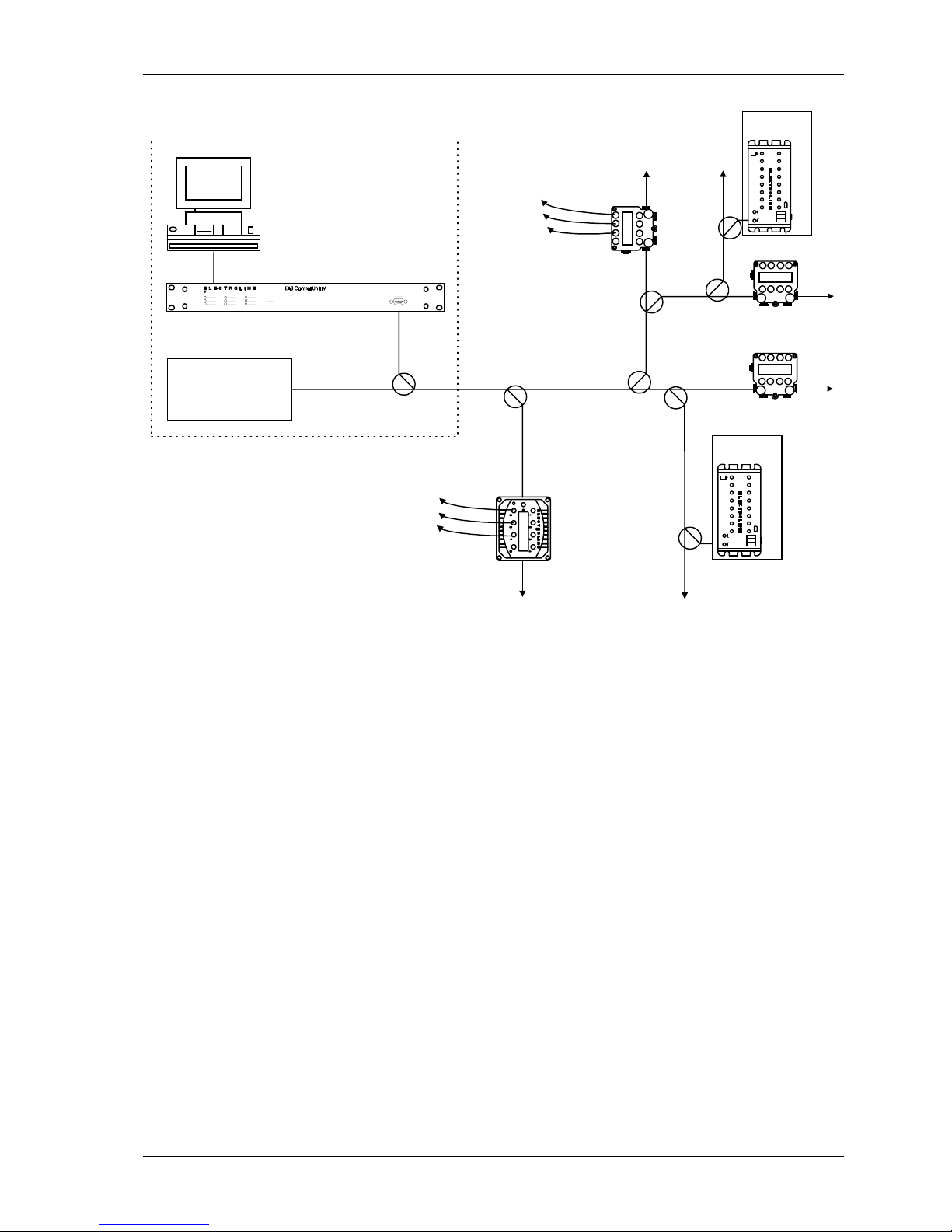
1.2.1 Subscriber tier management
When used in conjunction with a subscriber management system, the Control Unit remotely
switches the addressable taps deployed in the field according to the status (“hit”) it receives
from the billing system. For subscriber control, the status corresponds to a tier (e.g. basic or
pay). The Control Unit stores the status data in its memory, then encodes and transmits it on
a control carrier that is injected into the downstream cable signals. The carrier includes
encoded status messages for all the addresses in the Control Unit’s memory, regardless of
whether the address corresponds to a device installed in the cable plant or not.
1-2 529-0004 Ver.3
Page 15
Control Unit IV Reference Manual Product Description
Billing system
RS-232 or
LAN connection via an
Ethernet-RS-232 bridge
Control Unit
TV signals and other
services (e.g. Internet)
Cable Headend
FSK carrier
Subscriber
drops
Cable Network with Addressable Taps
Subscriber
drops
STT
Apartment
building
Apartment
building
STT
STT
To next
addressable tap
Figure 1-1: The Control Unit’s role in a cable TV network
529-0004 Ver.3 1-3
Page 16
Product Description Control Unit IV Reference Manual
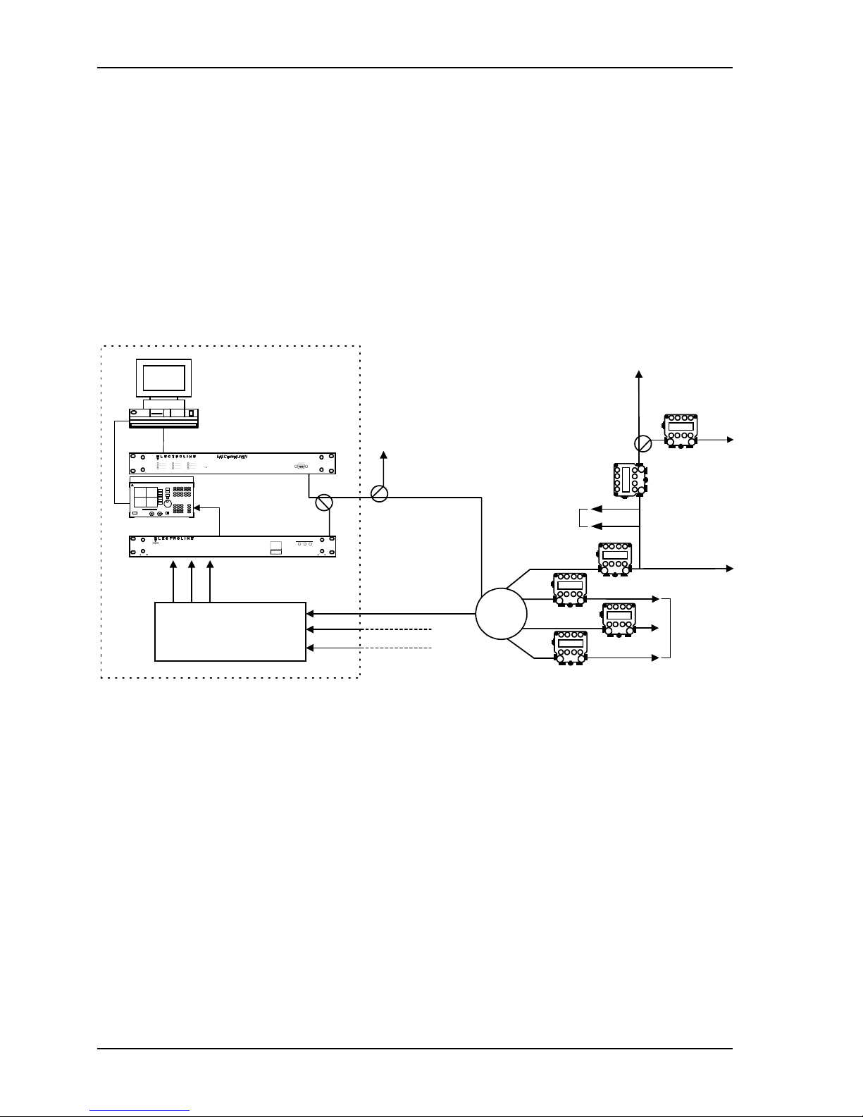
1.2.2 Return path monitoring
When used in conjunction with a CLEARPath control software for locating sources of
ingress, the Control Unit remotely switches CLEARPath modules (CPMs) and Test Point
Selectors (TPS) according to the status it receives from the control software. For return path
applications, the status can be a command to switch the CPM’s relay to the open position,
the closed position or through a 6 dB pad. For a Test Point Selector (TPS), the status
command is translated into selecting one of the TPS inputs. The Control Unit encodes the
software’s commands and transmits them to the TPS or CPMs in order to control the return
path. The Control Unit’s carrier is in the forward path, thus ensuring remote control of the
modules even if the return path needs to be cut off during network repairs.
CLEARPath
control
software
LAN connection via an
Ethernet-RS-232 bridge
Spectrum Analyzer
Fiber receivers
Return Path
Monitoring
Cable Network with Addresssable
CLEARPath Modules (CPMs)
Section of
Cable Headend
RS-232 or
To other
nodes
Control Unit
Test Point Selector MS
Test Point Selector
FSK carrier
Fiber link
From other fiber nodes
Subscriber drops
Fiber node
Figure 1-2: The Control Unit’s role in return path monitoring
CPM
CPM
CPM
CPM
CPM
Distribution legs
CPM
1-4 529-0004 Ver.3
Page 17

Control Unit IV Reference Manual Product Description
1.3 Features
1.3.1 Billing system and host computer interfaces
The Control Unit is normally used with a host computer such as a billing system. The
purpose of a billing system or other host computer is to update the status information in the
Control Unit’s memory. The underlying concept is the same for updating the status of
subscriber taps, CLEARPath modules and Test Point Selectors. Note that each addressable
device installed in the network is linked to a physical location at the time of installation, and
this link is recorded in the billing system or the host computer. The Control Unit does not
keep track of street addresses; it only stores the status information for each Electroline
group-tap address.
The Control Unit receives status information from the host computer on one of its RS-232
ports, using either a direct or modem connection or an Ethernet–RS-232 bridge. The Control
Unit accepts a variety of protocols (see Chapter 3). If the Control Unit is used in a return path
monitoring system, then Electroline’s proprietary communication protocol, ICOR, must be
used on the Control Unit’s port. For more details on Electroline’s control software and
communication protocols, contact an Electroline representative.
When the host computer modifies the status of a subscriber, it sends a message to the Control
Unit to update the subscriber status memory. The Control Unit always refreshes each
subscriber address as it scans its memory. The full scan cycle can be as short as a few
seconds or up to 25 minutes, depending on the Control Unit’s capacity (see Chapter 4 for
scan times).
1.3.2 Tiering systems
Each Control Unit can support one of the two main system types for controlling subscriber
tiers in the Electroline addressable system: off-basic-pay (OBP) or multi-tier. The system
type determines the number of tiers that the Control Unit can control for each subscriber
address.
An OBP system provides one or two exclusive service tiers. Exclusive tiers are tiers that
cannot be combined with each other. If only one tier is required, the choices are off and pay.
In a two-tier system, the choices are off, basic and pay.
A multi-tier system provides up to eight tiers and can be exclusive or inclusive. Inclusive
tiers can be combined with each other. The tiers are encoded using the letters A, B, C, D, E,
F, G and H. Only the tiers that are required are used. For example, if four tiers are offered,
then the choices will be A, B, C, and D.
You cannot modify the tiering system (OBP or multi-tier), which is set by Electroline
according to customer specifications. Contact Electroline’s technical support department if
you would like to change the tiering structure.
529-0004 Ver.3 1-5
Page 18

Product Description Control Unit IV Reference Manual
1.3.3 Subscriber capacity
The Control Unit’s capacity varies from 4,096 to 1,048,576 subscribers (see Table 1-2). The
number of subscribers per group is determined by the tiering system (OBP or multi-tier).
Both systems can handle up to 16,384 groups, but in an OBP system, a group contains 64
subscribers and in a multi-tier system there are 16 subscribers per group. This means that an
OBP system can control up to 1,048,576 subscribers, and a multi-tier system can control up
to 262,144 subscribers.
The second factor that causes the Control Unit’s capacity to vary is the nominal capacity of
the unit (see Table 1-2). Each unit is designed to control a certain number of addresses. For
example, a 32 K unit shipped to a cable operator contains all 32,768 addresses in its memory.
You cannot modify the number of subscribers. Contact Electroline’s sales department if you
would like to obtain a Control Unit with a larger capacity. Note that the time it takes to
refresh the tap status of all subscribers in the network (i.e. the sequencer’s scan time)
increases with the number of subscribers (see Chapter 4).
Table 1-2: Nominal and actual capacity
Nominal
Actual subscribers
capacity*
4K 4,096
32K 32,768
128K 131,072
256K 262,144
512K (OBP only) 524,288
1M (OBP only) 1,048,576
* The Control Unit is sold with a nominal capacity expressed in K, which is equal to 1024.
To calculate the actual number of subscribers your unit supports, multiply the nominal
figure by 1024. For units with 1M capacity, M equals 2
20
.
1-6 529-0004 Ver.3
Page 19

Control Unit IV Reference Manual Product Description
1.3.4 Redundancy system
Connecting two identical Control Units ensures system redundancy, allowing the backup unit
to take over if there is a problem with the master unit. This feature provides greater service
reliability. The master and backup units must have exactly the same firmware version and
setup (see Chapter 3 for setup).
1.3.5 Diagnostics
The Control Unit includes nine LEDs on the front panel:
FSK, MODEM
, and three RX/TX LEDs. The LEDs are used to monitor the Control Unit’s
POWER, MASTER, STATUS, BATTERY
,
operation. A complete troubleshooting table including the use of the LEDs to diagnose
problems can be found in Chapter 6.
At startup, the Control Unit’s firmware performs a series of self tests. When a terminal is
connected to the unit, the user can view the startup screen. If a system is in error, a message
or warning will appear on screen. A list of error messages is included in Chapter 6.
If an error occurs, the Control Unit’s reset button can be pushed to restart the unit without
powering off. The reset button returns the Control Unit to its initial state before the reset and
does not affect the information stored in its memory.
1.3.6 Upgradability
The Control Unit’s firmware, or operating system, is stored in the unit’s flash memory. The
unit comes with an upgrade program (CU4UP) on CD-ROM for installing a new version of
the firmware in the unit’s flash memory. Use this program only when you need to upgrade
the firmware (see Chapter 5 for upgrade instructions). Normally, a firmware upgrade is only
required if it has been recommended by Electroline’s technical support staff.
In addition to software and firmware upgrades, the Control Unit’s hardware can be upgraded
through the expansion slots on its main board (see section 1.4.2 for information on expansion
slots).
529-0004 Ver.3 1-7
Page 20
Product Description Control Unit IV Reference Manual
1.4 Physical characteristics
1.4.1 Enclosure
The Control Unit’s enclosure measures one rack unit high (1.75 in.), and mounts easily in a
standard 19-inch equipment rack. For rackmounting instructions, see Chapter 2. All
connectors are external to the Control Unit. The unit does not need to be opened for normal
operation, except to change the battery.
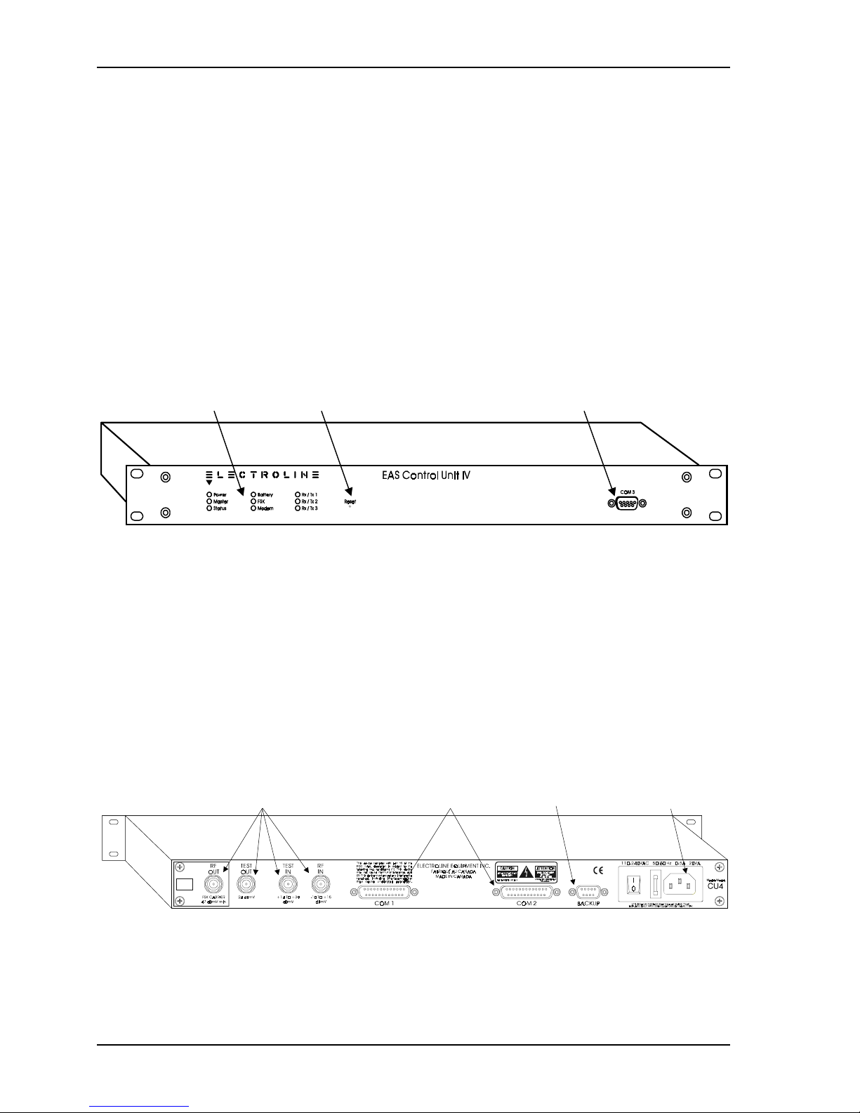
Front panel
All of the Control Unit’s system monitoring LEDs are located on the front panel. In addition
to the LEDs, COM3, which is the setup and diagnostic port, is also readily accessible on the
front panel. For more information on using the COM 3 port, see Chapter 3. For help
interpreting the LEDs, see Chapter 6.
LEDs Reset button Setup port
Figure 1-3: Front panel of the Control Unit IV
Rear panel
All cabling connections, except for the setup connection, are located on the rear panel: RF
inputs and outputs, COM ports, proprietary backup system port, and power entry module.
The Control Unit’s power entry module accepts 120 VAC/60 Hz or 240 VAC/50 Hz power
without requiring any hardware modifications. The appropriate power cord comes with the
Control Unit according to the country in which the unit is used. The Control Unit also comes
with two 250 V/2.5 A fast blow fuses, one of which is a spare fuse, to protect the power
supply from power surges. See Chapter 5 to replace a blown fuse.
RF inputs and outputs COM ports Backup port Power input
Figure 1-4: Rear panel of the Control Unit IV
1-8 529-0004 Ver.3
Page 21

Control Unit IV Reference Manual Product Description
Ports
The Control Unit’s COM 1, 2 and 3 are DCE-type serial ports. For more information on the
pinouts of the Control Unit’s ports, see Appendix B. The RF ports are all standard female
F-type connectors for connecting standard 75-ohm coaxial cable. Note that the
BACKUP
port
is not an RS-232 connector; only the Electroline redundancy cable should be connected to
this port if you have a redundancy system. See Chapter 3 for more details on redundancy
systems.
Table 1-3: Control Unit ports
Control Unit ports Purpose/Support
COM 1 or COM 2 When the Control Unit is installed alone, this port is used
for host computer connections (billing systems, etc.) with
CSG, ICOR, NTMF, SSMN, and Terminal protocols.
COM 1 When two Control Units are installed in a redundancy
system, this port is used for host computer connections
(same protocols as above).
COM 2 When two Control Units are installed in a redundancy
system, this port is used for synchronization (with backup
Control Unit), with preset communication parameters.
COM 3 For all Control Units, this port is used for setup (Terminal
protocol only).
BACKUP
connector When two Control Units are installed in a redundancy
system, this port is used for redundancy (with backup
Control Unit), with proprietary settings (not RS-232).
RF OUT
and
For all Control Units, these ports are used for RF
RF IN
connections (data carrier).
TEST IN
and
TEST OUT
For all Control Units, these ports are used for RF test
connections.
1.4.2 Internal features
The Control Unit’s open architecture makes it possible to upgrade or modify certain features:
the expansion slots allow the possibility of adding boards for specific applications and the
frequency-agile single FSK modulator allows cable operators to change the carrier’s
frequency.
529-0004 Ver.3 1-9
Page 22

Product Description Control Unit IV Reference Manual
Important:
Do not modify or change the components on the motherboard. Only replace the backup
battery and the fuse or add expansion boards as needed.
Expansion slots
The Control Unit has three expansion slots on the motherboard. On current models, the
RAM Expansion Board (see RAM section below) is preinstalled in the central expansion
slot. The two remaining slots have identical connectors, but different space availability: the
slot on the left accepts a larger board.
RAM
The Control Unit has 256 KB of RAM on board. Part of the Control Unit’s memory is used
to store the status of the subscribers, the TPS units or the CPMs, and the other part is used to
execute programs that switch the subscriber’s tap or the return path, or that carry out various
internal tests.
The plug-in RAM Expansion Board installed in the Control Unit provides an additional
1 MB of RAM. The additional memory gained with the RAM board can be used to support
special features such as churn analysis. If this board is not already installed, contact your
Electroline representative to place an order.
Battery
The Control Unit uses a lithium 3 VDC (CR2430 or CR2450) battery to maintain the
subscriber status information in the Control Unit’s RAM in case there is a power failure.
You must replace this battery about every two or three years, or when the battery LED on the
front panel is lit (see Chapter 5).
FSK modulator and demodulator
There are two kinds of modulators that produce an FSK carrier used by the Electroline
decoders deployed in the cable plant: dual FSK and single FSK.
Control Unit’s with a dual FSK modulator modulate the control carriers on two frequencies
in order to represent the binary elements of a data stream coming from the sequencer. The
nominal carrier frequency is indicated on the label near the RF output on the unit’s rear
panel.
Control Unit’s with a single FSK modulator are frequency agile over a given range, as shown
on the frequency range label next to the RF output on the unit’s rear panel. Since these units
are frequency agile, the carrier frequency shown on the rear panel may change. You can
check the frequency by using the Workabout to read the carrier (see the Electroline
Programmer/Monitor (EAS-PMW) User Guide for more details).
The Control Unit’s demodulator operates in the same way as the demodulators in the
Electroline addressable equipment deployed in the cable plant. The demodulator verifies the
presence and integrity of the signal that the Control Unit transmits to the cable network.
1-10 529-0004 Ver.3
Page 23

Control Unit IV Reference Manual Product Description
1.5 Reference
This chapter provides a basic overview of the Control Unit. For more information on
interfacing the Control Unit with a billing system, see Chapter 2 for cabling diagrams and
see Chapter 3 for a list of supported protocols. If you want to use the Control Unit to manage
subscribers manually, without using a billing system, see Chapter 4.
For more information on upgrading the Control Unit’s memory or firmware, see Chapter 5.
To find out more about the Control Unit’s self-diagnostic features and to troubleshoot
problems, see Chapter 6.
For pin assignments on the RS-232 cables used with the Control Unit, see Appendix B.
Contact your Electroline representative to obtain additional copies of this manual or to obtain
manuals for other products that are used with the Control Unit.
529-0004 Ver.3 1-11
Page 24

Page 25

INSTALLATION
Page 26

Page 27

Control Unit IV Reference Manual
2. INSTALLATION
This chapter provides step-by-step installation procedures for mounting and connecting the
Electroline Control Unit. It also includes tips and necessary safety precautions.
The procedures for installing the Control Unit are the same for units with dual FSK
modulators and for units with agile single FSK modulators. However, when addressable
devices that have single FSK decoders are installed in a network with a Control Unit using
dual FSK modulation, the Control Unit must be connected to a Data Repeater. Refer to the
Data Repeater’s installation manual.
Important:
For your safety, read sections 2.1 and 2.2 before installing the Control Unit.
2.1 Handling
Before plugging in the Control Unit, you should leave the unit in the place where it will be
installed until it reaches ambient temperature and all possible moisture on the internal
components has evaporated. This can take up to four hours. For more information, contact
Electroline to obtain specifications on the Control Unit’s operating and storage temperature
range.
2.2 Precautions
To prevent risk of damaging the equipment, we recommend that the Control Unit be
unplugged when it is being installed. Make sure the
off. For rack installation, make sure the rack is properly grounded.
Caution:
Only qualified personnel are authorized to open the Control Unit.
POWER
LED on the unit’s front panel is
529-0004 Ver.3 2-1
Page 28
Installation Control Unit IV Reference Manual
2.3 Mounting the unit
For best RF performance and for maximum protection against the risk of electric shock, we
strongly recommend that you mount the Control Unit in a properly grounded rack.
2.3.1 Hardware requirements
• standard 19-inch wide EIA equipment rack with one free space (two spaces are required
if you are also installing a backup unit)
• four sets of ¾-inch 10-32 screws, plastic cup washers and clip nuts (supplied with the
Control Unit)
• Phillips head screwdriver
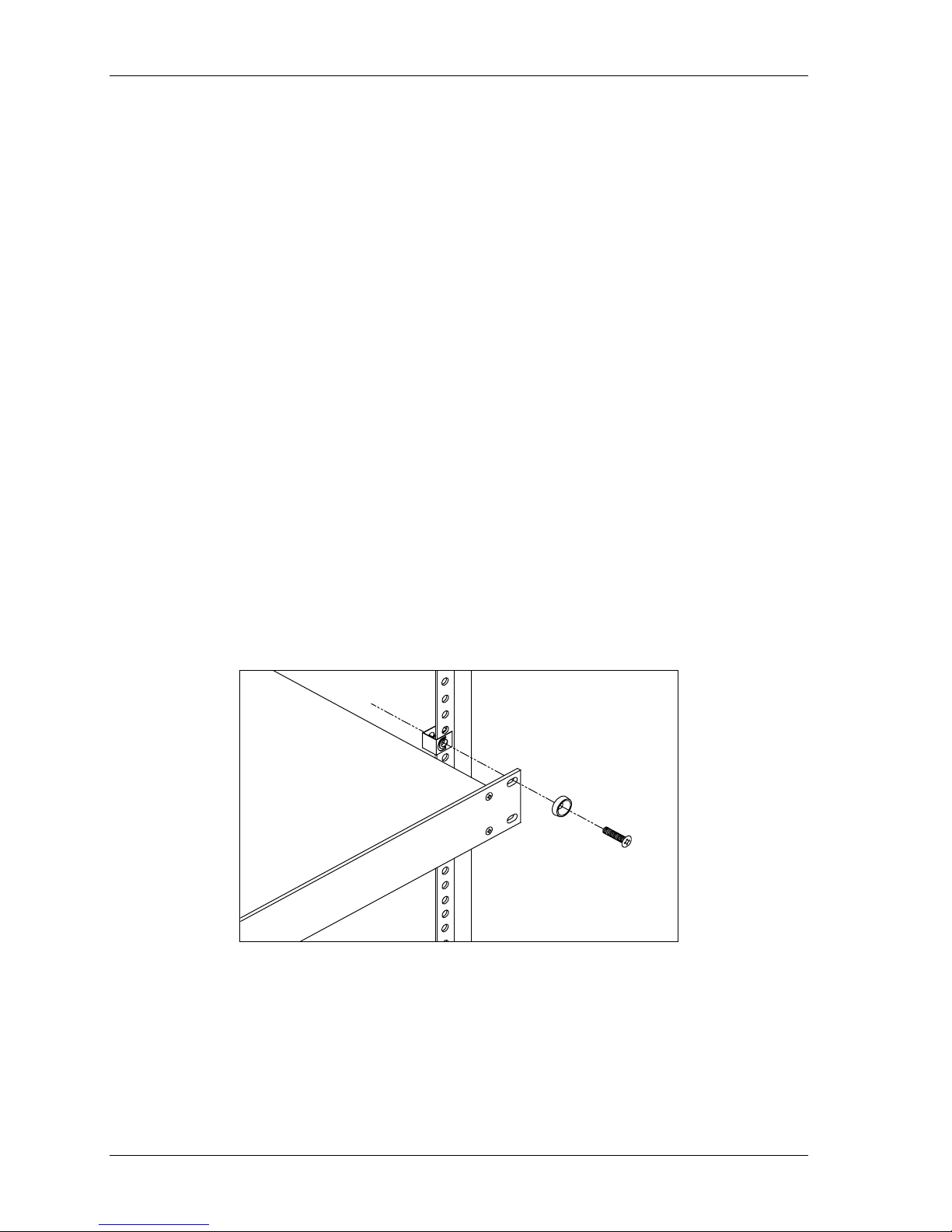
2.3.2 Mounting the unit in a rack
1. Place a clip nut on each hole on the rack.
2. Put a plastic cup washer on each screw.
3. Insert the Control Unit in a free space in the rack.
4. Align the four ¼-inch mounting holes on the Control Unit’s front panel over the rack’s
holes (you may require the assistance of another person to hold the Control Unit in
place).
5. Secure the unit to the rack by inserting a screw with a plastic cup washer into each hole
on the front panel of the unit and then hand-tighten each screw.
6. Tighten each screw with a Phillips head screwdriver.
Figure 2-1: Installation of the unit in an equipment rack
2-2 529-0004 Ver.3
Page 29

Control Unit IV Reference Manual Installation
2.4 Setting up the host computer
This procedure sets up a computer so that you can establish a connection with the Control
Unit. There are two main types of connection: one is for setup and the other is for data
exchange. The connection you choose depends on how the host computer is being used.
Host computer used to set up the Control Unit
During the setup process, the host computer (PC, terminal or Workabout) communicates
with the Control Unit on the unit’s COM 3 port. The communication parameters on this
port cannot be changed. Therefore, the host computer’s communication parameters must
correspond to the Control Unit’s COM 3 parameters as shown in Chapter 3, which also
explains all the steps for setting up the Control Unit.
Host computer used to exchange data
When you want to use the host computer to exchange data such as subscriber status
information, you can set the computer’s communication port to other values on the
condition that they match the values of the Control Unit’s port (see Chapter 3 under
Setting up the COM ports).
2.4.1 Using HyperTerminal to set up a link with the Control Unit
The HyperTerminal software that comes with Windows 95 is used in the following example.
Do not use HyperTerminal for Windows 98. If you are using Windows 98, either downgrade
your version of HyperTerminal to the Windows 95 version, or obtain the most recent version
of HyperTerminal from the Hilgraeve website. You can continue to use the Windows 98
operating system. However, please note that you can use the HyperTerminal software that
comes with Windows 2000 and Windows ME. You can also use any other communication
program such as Procomm, or a standard terminal or the Workabout (see section 2.4.2).
To set up the host computer’s communication parameters using HyperTerminal:
1. Start the HyperTerminal software using the Start menu in Windows. Using the pulldown
menus, select Programs, then Accessories, then HyperTerminal. Run the program by
clicking on the HYPERTRM.EXE file. After the program loads, the connection
description window appears on screen. If HyperTerminal is already running, select New
Connection from the File menu.
2. In the connection description window, enter a name and choose an icon for the
connection. Click
to continue.
OK
529-0004 Ver.3 2-3
Page 30
Installation Control Unit IV Reference Manual
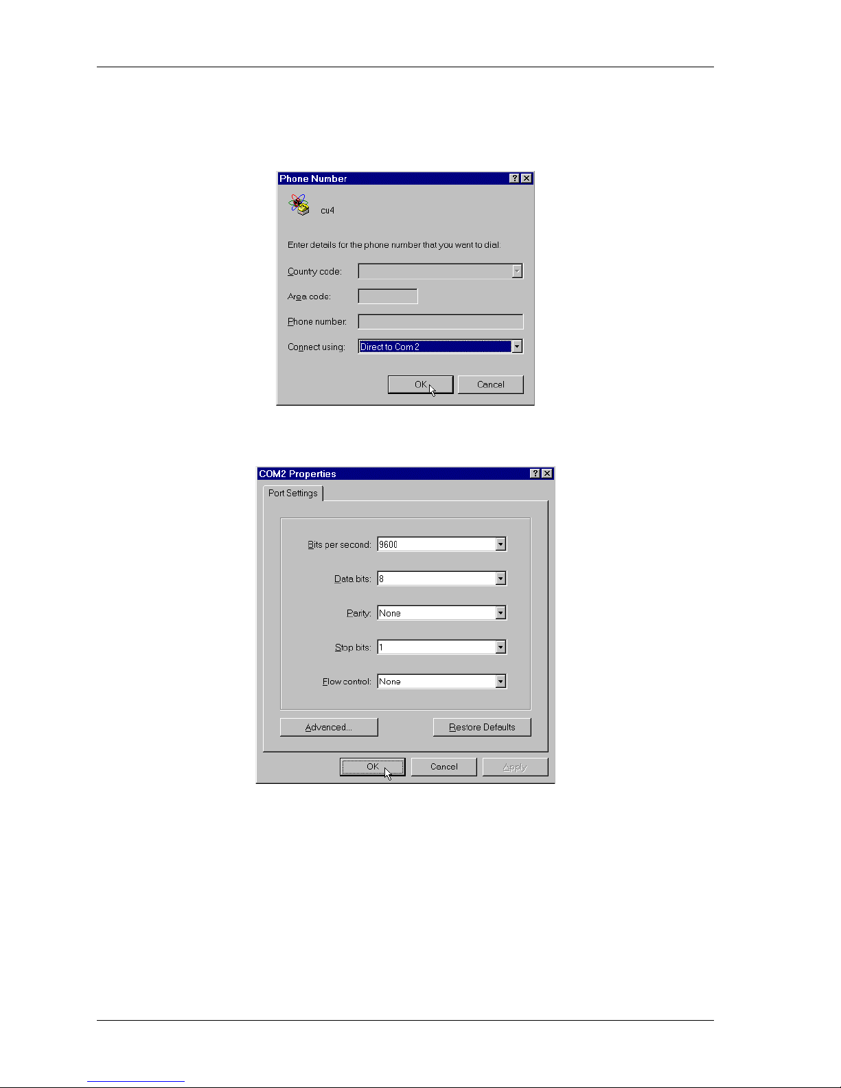
3. In the Phone Number window, go to the Connect using field and select a
communication port for the host computer that is not used by other devices. For
example, select Direct to Com 2.
Click OK. This calls up the communication port properties window for the port you have
selected.
4. Set up the communication port by choosing a value for each parameter. If you are going
to use the connection to set up the Control Unit, select 9600 bps, 8 data bits, 1 stop bit,
no parity and no flow control. If you are going to use the connection to exchange data,
select the parameters that match the Control Unit’s port you will be using (COM 1 or
COM 2). Click
2-4 529-0004 Ver.3
to complete the setup.
OK
Page 31

Control Unit IV Reference Manual Installation
5. To display the commands and instructions received during communication, use the File
menu in the menu bar and select Properties. When the Properties window opens, select
the Settings tab and click the
ASCII SETUP
button.
6. This calls up the ASCII setup window. Check the Echo typed characters locally box,
and click OK to return to the Properties window.
7. When the Properties window reappears, click
again. Your connection is now ready to
OK
be used to communicate with the Control Unit. It can also be used to set up the modems.
529-0004 Ver.3 2-5
Page 32

Installation Control Unit IV Reference Manual
2.4.2 Using the Workabout to set up the Control Unit
Electroline’s tool for programming addressable devices is a software that runs on a handheld computer called the Workabout. Normally, the Workabout is used only to run the
Electroline software, but it also includes a terminal emulation mode that can be used to
access the Control Unit’s setup menu. Follow the instructions in this section to use the
Workabout as a setup terminal.
To set up the Workabout’s communication parameters:
1. If the Electroline EAS-PMW software is running on the Workabout, exit the program by
pressing <∪+X>. The main screen with the icons should appear.
2. Select the Comms icon (scroll through the icons with the <→> key) and press <Enter>.
3. Press <Menu> and use the <→> key to go to the Scrn menu.
4. From the Scrn menu, choose Options to open the emulation options window. Select On
in the Local echo field by pressing the <→> key, and then press <Enter>.
5. Press <Menu> again, and use the <→> key to go to the Spec menu.
6. From the Spec menu, choose Port to open the port settings window. Set the port’s baud
rate to 9600, and choose port A by pressing the <→> key.
7. Press <Enter> to return to the terminal emulation window.
8. Using a standard RS-232 cable, or the 24” DB-9 to DB-9 cable (#WKB-PAC2) that
comes with the Workabout, connect the RS-232 port on the Workabout to the COM 3
port on the Control Unit.
(or standard RS-232 cable)
Connect to RS-232 port on
DB-9 flat cable
Workabout
Figure 2-2: Connecting the Workabout to the Control Unit’s COM 3 port for setup
You are now ready to log on to the Control Unit’s COM 3 port. See Chapter 3 for detailed
setup instructions.
2-6 529-0004 Ver.3
Page 33

Control Unit IV Reference Manual Installation
2.5 Setting up a modem
This procedure assumes that the Control Unit and the host computer (e.g. billing system)
require modems to communicate. If the host computer and the Control Unit are connected
over a direct link, disregard this procedure.
Note that if you are using a modem recommended by Electroline, contact the technical
support department for detailed modem setup procedures. The following procedure is
intended as a guideline for modem setup.
Follow the steps below to set up the modem that will be directly connected to the Control
Unit. Use the communication software running on your computer to set up the modem. See
your system administrator to set up the modem connected to the host computer.
To set up the modem directly connected to the Control Unit’s port:
1. Connect the male DB-25 end of the RS-232 cable to the modem. Connect the female
connector to an available port on the computer.
2. Plug one end of the power cord supplied with the modem into the modem’s power input.
Plug the other end into an AC power source.
3. Turn on the modem.
4. Run the computer’s communication software (for example, Windows 95 version of
HyperTerminal, Procomm, etc.).
5. Set up the modem. The Control Unit functions with the following parameters:
• ignore DTR
• no data compression
• no error correction
• hardware flow control
• set modem speed to the same setting as the modem-to-modem connection speed
(maximum: 38,400 bps; recommended: 9600 bps)
6. When the modem has been set up, turn off the modem and unplug the power cord from
the AC power source and from the modem.
7. Disconnect the RS-232 serial cable from the modem and the computer. The modem is
now ready to be installed on the Control Unit (see section 2.7.1). Make sure you use a
null modem cable for the modem-Control Unit connection. If you wish to now set up the
modem that will be directly connected to the host computer, do not disconnect the
RS-232 cable from the computer. Instead, disconnect only the modem. Reconnect the
cable to another modem that will be installed on the host computer, and see your system
administrator or contact Electroline’s technical support department before setting it up.
529-0004 Ver.3 2-7
Page 34

Installation Control Unit IV Reference Manual
2.6 Cable assemblies and applications
The Control Unit requires various cables, connectors and adapters to interface with a host
computer, peripheral devices and measuring instruments. Figure 2-3 illustrates the main
cables the Control Unit uses whether it is installed alone or with a backup unit. Figure 2-4
shows the cables that are used with a backup unit.
Standard cabling instructions are provided in sections 2.7.1 to 2.7.4. Additional instructions
for redundancy system cabling are provided in section 2.7.5.
(2) RS-23 2 ca bles
with 25-pin M-F
connectors
(1) RS-23 2 ca ble
with 9-pin M-F
connectors
(1) Three-w ire
power co rd with
M-F connectors
Figure 2-3: Connection cables for a single Control Unit
(1) 25-pin M-F-M
three-way ribbon
cable
(1) 25-pin M-M
synchronization
cable (null modem)
(1) 9-pin M-M
redundancy
cable
Figure 2-4: Redundancy kit cables
2-8 529-0004 Ver.3
Page 35

Control Unit IV Reference Manual Installation
2.7 Connecting the Control Unit
This section covers all the cabling instructions for the Control Unit, whether it is used alone
or used with a backup unit in a redundancy system. Figure 2-5 shows the cabling diagram for
a single Control Unit; Figure 2-6 shows the cabling diagram for two Control Units connected
together in a redundancy system setup.
The female connectors labeled COM 1 and COM 2 provide serial ports for local or remote
data exchange between the Control Unit and the host computer. These ports are usually set
up to support packet-switched protocols such as SSMN, ICOR, NTMF, CSG, etc. or the
Terminal protocol. However, you can set these ports up according to your requirements. For
information on communication protocols, see Chapter 3.
Use only for
redundancy
system
Coaxial cable
Headend
combiner
CATV network
Null modem
cable
Modem
Remote link
Direct connection
Phone network
To host computer
Modem
To LAN
Remote link
Direct connection
To host computer
Figure 2-5: Control Unit connection
Null modem
Modem
Phone network
Modem
cable
529-0004 Ver.3 2-9
Page 36

Installation Control Unit IV Reference Manual
2.7.1 Connecting the Control Unit to the host computer or modem
To connect COM 1 or COM 2 to the host computer or modem, or to an Ethernet–RS-232
bridge, you will need the following equipment:
Direct link
• standard RS-232 cable with DB-25 connectors no longer than 15 meters (50 feet)
Modem
• RS-232 null modem cable with DB-25 connectors no longer than 15 meters (50 feet)
• telephone extension cord with RJ-11 connectors
• modem
LAN connection
• Ethernet–RS-232 bridge
• standard RS-232 cable with DB-25 connectors no longer than 15 meters (50 feet)
• category 5 cabling with RJ-45 connectors
If you want to connect the Control Unit to a host computer using an RS-232 connection:
1. Connect one end of the RS-232 cable with DB-25 connectors (standard cable for direct
link, or null modem cable for modem link) to one of the connectors labeled COM 1 or
COM 2.
2. Connect the opposite end of the cable to the serial port on the host computer or modem.
3. If you have connected the Control Unit to a modem, plug one end of the telephone
extension cord into the line jack on the modem and the other end into the wall telephone
jack.
If you want to connect the Control Unit to a host computer using a LAN connection:
2. Connect a standard RS-232 cable with at least one DB-25 connector to either COM 1 or
COM 2 on the Control Unit. Connect the other end to a port on an Ethernet–RS-232
bridge.
3. Plug one end of a category 5 cable to the Ethernet–RS-232 bridge and connect the other
end to the Ethernet network.
The Control Unit is now ready to receive subscriber information from the host computer
directly, by modem, or via a LAN connection (Ethernet bridge).
2-10 529-0004 Ver.3
Page 37

Control Unit IV Reference Manual Installation
2.7.2 Connecting the Control Unit to the CATV network
The Control Unit transmits subscriber data to the CATV network from its RF output, which
is connected to the headend’s main combiner. The FSK carrier will then be injected into the
CATV network. Use a 75-ohm coaxial cable for this connection.
To connect the Control Unit to the cable network:
1. Connect one of the coaxial cable’s male connector to the F-connector labeled RF
OUT
on
the rear panel of the Control Unit.
2. Connect the other end of the coaxial cable to the headend combiner or directional
coupler. Make sure that the amplitude of the Control Unit’s carrier is adjusted to the
recommended level, which is 15 dB below the adjacent video carriers.
2.7.3 Connecting the Control Unit’s test ports
The standard configuration of the
TEST OUT
Control Unit and to connect a loop from the network (if applicable) to the
output is to connect it to the
TEST IN
RF IN
input on the
input. The
loop from the network is optional (see step 2).
1. On the Control Unit, run a short coaxial cable jumper from the
TEST IN
connector.
2. Connect a coaxial cable from the network to the Control Unit’s
TEST OUT
RF IN
connector to the
connector. Make
sure the signal level on this cable is within the Control Unit’s input range (see label).
This loopback connection enables the Control Unit to monitor its own signal from the
network. Skip this step on the backup unit in a redundancy system.
2.7.4 Connecting the Control Unit’s power cord
1. Make sure that the Control Unit’s on/off switch is in the off position (see the rear panel
diagram in Chapter 1).
2. Connect the female end of the power cord to the three-pin power connector on the rear
panel of the Control Unit.
3. Plug the male end of the power cord into an AC power source (e.g. wall outlet).
4. Turn on the Control Unit by putting the on/off switch in the on position. If the Control
Unit is receiving AC power, the
be lit.
POWER
LED on the front panel of the Control Unit will
529-0004 Ver.3 2-11
Page 38

Installation Control Unit IV Reference Manual
2.7.5 Connecting a master unit to a backup unit
To connect a master unit to a backup unit, you must use the redundancy kit (see Figure 2-4),
which includes a redundancy cable, a three-way ribbon cable and a synchronization cable.
For cabling, follow this procedure and refer to the connection diagram (see Figure 2-6).
1. Connect the master end of the redundancy cable to the
BACKUP
This connection ensures that the Control Unit that has the end labeled
master unit at startup. Connect the other end to the
BACKUP
2. Connect one end of the synchronization cable to the COM 2 port on the master unit and
connect the other end to the COM 2 port on the backup unit (see Figure 2-6). In a
redundancy system, COM 2 takes on its preset values (see Chapter 3).
3. To connect a host computer to the COM 1 port on the Control Unit, use the three-way
ribbon cable. Connect the male DB-25 connectors to COM 1 on both Control Units, then
connect the female connector to a computer, a modem or an Ethernet-RS-232 bridge as
follows:
• To connect the host computer using a direct link, connect the male end of a round
RS-232 cable (DB-25) to the female connector on the three-way ribbon cable.
Connect the female end of the round RS-232 cable to the computer’s communication
port.
• To connect the host computer using a remote link, see section 2.7.1 for modem
connection instructions.
• To connect a host computer to the Control Unit using a LAN connection, connect the
male end of a round RS-232 cable (DB-25) to the female connector on the three-way
ribbon cable. Connect the female end of the round RS-232 cable to an external
Ethernet–RS-232 bridge.
4. If you have not yet connected the Control Unit’s test ports, run a short coaxial cable
jumper from the
TEST OUT
connector to the
TEST IN
connector on each Control Unit. Do
not connect the two units to each other on these ports.
5. Connect a coaxial cable to the master unit’s
RF OUT
connector on the rear panel. Use
another coaxial cable and repeat this step with the backup unit.
6. Connect the free end of both coaxial cables to two free inputs on the headend combiner.
Make sure that the amplitude of the Control Unit’s carrier is adjusted to the
recommended level, which is 15 dB below the adjacent video carriers.
7. Connect the female end of each power cord to the three-pin connector on each Control
Unit.
8. If you have not yet done so, plug the male end of each unit’s power cord into an AC
power source. To avoid loss of service due to a power failure, use an uninterruptible
power supply (UPS).
input on the master unit.
MASTER
is the
input on the backup unit.
2-12 529-0004 Ver.3
Page 39

Control Unit IV Reference Manual Installation
Important:
The master unit and the backup unit must have exactly the same setup and
firmware version (see Chapter 3).
Master Unit
"MASTER"
connector
cable
Coaxial
Headend
combiner
cable
Coaxial
Coaxial jumper
Cable for
direct link
(DB-25 M-F)
Host computer
Coaxial jumper
Ribbon cable
DB-25 M-F-M
Synchronization cable
(DB-25 null modem cable)
cable DB-9
Redundancy
Backup
unit
529-0004 Ver.3 2-13
Figure 2-6: Connections in a redundancy system
Page 40

Installation Control Unit IV Reference Manual
2.7.6 Connecting the Control Unit for setup
The COM 3 port is used to set up and upgrade the Control Unit’s firmware. It can also be
used for troubleshooting. To connect the COM 3 port to the host computer or the
Workabout, you must use an RS-232 cable with DB-9 connectors.
1. Connect the cable’s male DB-9 connector to the COM 3 port on the unit’s front panel.
2. Connect the female connector to the host computer’s serial port or to the RS-232 port on
the Workabout.
Male DB-9 connector
Connect to Control Unit's
COM 3 for setup
Female DB-9 connector
Connect to a computer or
terminal for setup
Figure 2-7: Connecting the Control Unit’s COM 3 port to a computer for setup
The Control Unit is now ready to be set up. See Chapter 3 for instructions.
2-14 529-0004 Ver.3
Page 41

SETUP
Page 42

Page 43

Control Unit IV Reference Manual
3. SETUP
This chapter provides the information you need to set up the Control Unit. Each of the
Control Unit’s various setup commands is explained along with practical examples.
This chapter also provides an overview of the communication protocols that are supported on
the Control Unit’s COM ports. It is important to use the appropriate protocol to ensure that
the Control Unit can interface with your billing system or with any other type of host
computer.
3.1 COM port characteristics
The Control Unit is equipped with three RS-232 DCE-type local access ports (COM 1,
COM 2 and COM 3), which are used to exchange data with the host computer, either locally
or by modem. The COM 1 and COM 2 ports are normally set up to receive packet-switched
protocols (ICOR, CSG, NTMF or SSMN) or the interactive Terminal protocol. You can
change the setup of these two ports if necessary (see section 3.6.6).
During the setup session, the COM 1 and COM 2 ports are disconnected to prevent incoming
commands from being processed while the session is under way. However, during the
session the Control Unit continues to transmit the data stored in its memory to the cable
network. This feature maintains service on the addressable taps in the field. New service
changes from a subscriber management or billing system will be received only after exiting
the setup session.
The COM 3 port is used to set up and upgrade the Control Unit, to monitor for failures, and
to control subscribers manually. The Terminal protocol is mandatory on COM 3. This
protocol is preinstalled on COM 3 and can also be used on COM 1 and COM 2. To
communicate with one of the Control Unit’s ports that is set up with the Terminal protocol,
you must use a passive DTE-type terminal or the Workabout. The terminal must be able to
run at the same speed as the Control Unit. You can use communication software such as the
HyperTerminal software that comes with Windows 2000 and Windows ME, or any other
communication program such as Procomm. Do not use HyperTerminal for Windows 98. If
you are using Windows 98, either downgrade your version of HyperTerminal to the
Windows 95 version, or obtain the most recent version of HyperTerminal from the Hilgraeve
website. You may continue to use the Windows 98 operating system.
Note that there may be long processing delays for certain commands. Since the Control Unit
operates on a first come, first served basis, the processing time varies as a function of any
command that is already being processed. Moreover, the Control Unit can receive commands
on all communication ports at once. This means that commands that were initiated on one
port can be undone on another port. For example, if a tap’s status is changed by the billing
system on COM 1, then a manual command on COM 3 can change the tap’s status again.
529-0004 Ver.3 3-1
Page 44

Setup Control Unit IV Reference Manual
3.2 COM port protocols
The Control Unit can interface with a host computer or billing system on its COM 1 or
COM 2 port. These ports can support either a terminal-based protocol or one of the four
packet-based protocols described in this section. COM 3 is normally reserved for setup and
monitoring, and requires the use of the Terminal protocol.
3.2.1 Terminal protocol
The Terminal protocol is a manual command interface that requires user input on a terminal
or computer. The user enters simple commands, usually with one or more parameters, to
access all of the Control Unit’s functions. The Control Unit responds immediately to the user
input.
The Terminal protocol supports both OBP and multi-tier systems. It is the only protocol that
can be used to connect to the Control Unit for a setup session, which requires a password
entry on COM 3.
The Terminal protocol also allows you to enter diagnostic commands on any of the Control
Unit’s ports that use this protocol. No password is required for diagnostics.
3.2.2 Packet-switched protocols
The Control Unit supports several packet-switched protocols, as shown in Table 3-6 on
page 3-17. For each protocol, one or more “flavors” (types) may be available. Electroline
develops flavors to take into account variations in the protocols. For example, CSG 2T has
several variations that modify the way it responds to different identification codes. The first
protocol developed is called “Base” and the subsequent protocols are called “Ext A”,
“Ext B”, etc.
For more information on these protocols, contact Electroline’s technical support department.
The content and the meaning of these protocols may be provided on request, with
Electroline’s authorization only.
Table 3-1: Control Unit protocols used with various billing system providers
Billing System Provider Protocol
AZAR
CSG Systems CSG
DST Innovis (formerly CableData)
ICOMS (Convergys), formerly
CableMaster (CBIS)
CSG
CSG
ICOR
Proxima ICOR
R&R Enterprises CSG
Rogers Supersystem SSMN
3-2 529-0004 Ver.3
Page 45

Control Unit IV Reference Manual Setup
3.3 Access levels
There are two user access levels: limited access and full access. Users with limited access do
not need a password. If you have limited access, you can use basic commands such as
displaying the unit’s setup, and showing the status of one or more subscribers.
Users with full access to the system need a password in order to use additional commands
that are not accessible to a limited access user. If you have full access, once you log on (see
important note below), you can use commands that affect subscriber services and the unit’s
operation. For example, you can modify the status of one or more subscribers, download and
upload data in the memory, change the user password, reset and set up the Control Unit. You
can switch from full access to limited access by typing
Important:
The default password is abcde. This password should be modified the first time you log
on for security reasons (see section 3.6.4). Make sure that the system administrator is
informed of the new password.
logoff
.
At all times, you can view the list of commands and their description by typing
help
or by
typing ? (see sections 3.3.1 and 3.3.2). In the main menu, the asterisk * that appears after the
description of certain commands means that the command can cause processing delays on
the other communication ports. The Control Unit is a multi-user device but it processes
requests one at a time, and some requests require a longer processing time.
In the description of each command on screen, the square brackets [ ] indicate that the
parameters are optional. For example, the command
time
used alone displays the time. If
the command is used with a parameter [hh:mm:ss], it sets the time. Do not type the square
brackets when using the command.
Note that the
locate
and
search
commands are available only in OBP mode. Full access
is required to initiate these commands.
529-0004 Ver.3 3-3
Page 46

Setup Control Unit IV Reference Manual
3.3.1 Limited access
Limited-access users can use all the commands in this section; no password is required. To
view the list of commands available to a limited-access user once you are connected to a
Control Unit:
1. Press <Enter> to display the CU4> prompt.
or
?
and press <Enter> to display the main menu.
2. Type
CU4>help
Terminal Protocol
info Show system info
time [hh:mm:ss] Read [set] time
date [wkday-mth-day-yr] Read [set] date (Sun=1 & 2000=00)
chkram Verify status RAM *
tap <g,t> Read a tap status
grp <g[,ng]> Read entire group[s] status *
find <status g[,ng]> Find occurrences of specified status *
log <pw> Logon as special user
* Use of these functions may cause a delay on other ports.
help
3.3.2 Full access
Users with permission to access extended features of the Control Unit’s firmware can use the
commands in this section. A password is required at logon. To view the list of commands
available to a full-access user once you are connected to a Control Unit:
1. Press <Enter> to display the CU4> prompt.
2. Log on with a valid password (see section 3.6.1) to access a set of additional commands
and press <Enter>.
3-4 529-0004 Ver.3
Page 47

Control Unit IV Reference Manual Setup
C
r
p
3. Type
help
or
?
and press <Enter> to display the command menu.
CU4>help
Terminal Protocol
info Show system info
time [hh:mm:ss] Read [set] time
date [wkday-mth-day-yr] Read [set] date (Sun=1 & 2000=00)
chkram Verify status RAM *
tap <g,t> Read a tap status
grp <g[,ng]> Read entire group[s] status *
find <status g[,ng]> Find occurrences of specified status *
locate <g> Identify tap when off or basic *
search <g> Identify tap when off, basic or pay *
stap <status g,t> Set a status for a specified tap
sgrp <status g[,ng]> Set group[s] to specified status *
sendgrp <g> Refresh group
setseq <g> Set sequencer to specified group
download <g,ng> Download status of specified groups *
upload Upload status *
sync Synchronize databases *
setup Enter configuration mode *
logoff Return to normal user access
setpw <oldpw newpw> Change system password
reset Software reset
* Use of these functions may cause a delay on other ports.
ommands
equiring a
assword
3.3.3 Logging off a session
To log off a session or to change from a full-access level to a limited-access level:
1. Press <Enter> to display the CU4> prompt.
2. Type
logoff
and press <Enter>. The message System logoff will appear.
529-0004 Ver.3 3-5
Page 48

Setup Control Unit IV Reference Manual
3.4 Viewing the unit’s setup
info
The
the system type, the RF watchdog status, the battery’s status, the available memory and the
COM port setups.
command displays information on the Control Unit’s status and setup. It shows
1. At the CU4> prompt, type
info
and press <Enter>. The following information appears
(exact system information depends on your setup):
CU4>info
Control Unit IV 3.01
System: OBP mode, 32768 customers, CU4 ID: 0, Carrier tag:0
Redundancy Failure Notification: ON
RF Watch dog: OK
Version:2 Carrier: detected
Config: enabled, bit stream from RF on TEST IN
On error, don't toggle the redundancy circuitry and warn
the CPU
Redundancy monitoring system: OK
Secondary Unit - Present: NO
Battery good
RAM available: 262144 bytes, scanning 8192 bytes
Current port is 3
COM 1=9600 bps, NO parity, 8 data bits, 1 stop bit(s),
NO flow control, Protocol: Terminal, Flavor: Base
COM 2=9600 bps, NO parity, 8 data bits, 1 stop bit(s),
NO flow control, Protocol: Terminal, Flavor: Base
COM 3=9600 bps, NO parity, 8 data bits, 1 stop bit(s),
NO flow control, Protocol: Terminal, Flavor: Base
CU4>
2. Make sure this information is correct. Note that:
• In the “system” information, the mode indicated tells you which format is used to
send messages on the RF carrier. The message format corresponds to the system type,
and can be either OBP or multi-tier. The mode is preset in the factory and cannot be
changed.
• The number of customers is the total number of subscribers that the Control Unit can
support. The Control Unit can control over one million subscribers depending on the
capacity of your Control Unit. The capacity is preset in the factory and cannot be
changed.
• The Control Unit IV’s identification number (CU4 ID) corresponds to the “Head-end
code” that the previous model of the Control Unit uses.
3-6 529-0004 Ver.3
Page 49

Control Unit IV Reference Manual Setup
• The carrier tag is the number associated with a carrier frequency generated by a
particular Electroline Control Unit (single FSK carrier). The tag is preset in the
factory to 0, but the cable operator can change it.
• The redundancy failure notification is an optional feature in a redundancy system that
can be activated so that the host computer will be warned if a master-backup switch
occurs.
3.5 Starting a setup session
In order to make the Control Unit easier to install and use, Electroline sets up the unit in
advance, according to the customer’s specifications. You can, however, modify some of the
setup parameters.
Important:
If you are connecting to the Control Unit for the purpose of changing its settings (
synchronizing a master and backup unit (
setpw
(
), the following restrictions apply:
sync
) or changing the system password
setup
),
• You must connect the host computer to the Control Unit’s COM 3 port.
• The host computer’s own COM port must be set up with the parameters in Table 3-2.
Because the COM 3 port is used to set up the Control Unit, its parameters are programmed in
the factory and cannot be modified. Make sure that your HyperTerminal connection or other
communication program uses the same settings on the computer’s COM port when
connecting to COM 3.
Table 3-2: Mandatory parameters on COM 3
Parameters Values
Bits per second........ 9600
Flow control............ none
Parity....................... none
Data bits.................. 8
Stop bits .................. 1
529-0004 Ver.3 3-7
Page 50

Setup Control Unit IV Reference Manual
3.6 Setup procedure
To start a setup session you must first establish a connection with the Control Unit. Follow
the procedure for establishing a connection as explained in Chapter 2.
The commands in this section require full-access privileges. Therefore, you must log on with
a password. For more information on access privileges, see section 3.3.
3.6.1 Logging on with a password
When you log on with a password, you have full access to commands that may have major
repercussions on the unit’s operation. For the list of commands available to full-access users,
refer to section 3.3.2.
The password is shared, i.e. you must use the same password to log on to all three
communication ports. However, you can only modify the password through COM 3.
Moreover, access on the three ports is independent, meaning that you can log on to COM 1
without logging on to COM 2 (assuming that the Terminal protocol is used on COM 1
and COM 2).
To log on:
1. Press <Enter> to display the CU4> prompt.
2. Type
log
<password> and press <Enter>.
The password must not be longer than 15 characters and cannot have spaces. The default
password is abcde. You must use this password the first time you log on to the Control
Unit to establish a session. You should change the password to safeguard your system.
See section 3.6.4 on page 3-10.
A message confirming that you were granted access appears:
CU4>log abcde
Access granted
3.6.2 Setting the time
To set the time on the Control Unit:
1. Press <Enter> to display the CU4> prompt.
2. To display the Control Unit’s current time, type
time
displaying the time appears:
CU4>time
Current time is: 14:29:32
The time displayed is based on the 24-hour international system. It may differ slightly
from the actual time (±1 second). The time format is {HH:MM:SS}.
hours: 1-24 (for example, 14:00 means 2:00 PM)
minutes: 1-60
seconds: 1-60
and press <Enter>. A message
3-8 529-0004 Ver.3
Page 51

Control Unit IV Reference Manual Setup
3. To change the Control Unit’s time, type
time
followed by the current time in the format
hh:mm:ss, and press <Enter>. Note that all users can display the time, but only fullaccess users can set the time.
A message confirming the new time appears:
CU4>time 14:31:04
Current time is: 14:31:04
The time displayed may differ slightly from the actual time (±1 second).
3.6.3 Setting the date
To set the date on the Control Unit:
1. Press <Enter> to display the CU4> prompt.
2. To display the Control Unit’s current date, type
displaying the date appears:
CU4>date
Current date is: Tuesday, 11-06-2001
The date display format is: Weekday, mm-dd-yyyy.
3. To set the Control Unit’s date, type
date
, enter the current date in the format
ww-mm-dd-yy and press <Enter>. Note that all users can display the date, but only fullaccess users can set the date.
date
and press <Enter>. A message
ww = weekday expressed as a number from 1-7; the first day of the week is Sunday (1).
mm = month expressed as a number from 1-12
dd = day of the month
yy = year expressed as the last two digits of the year; year 2000 is represented by
double zeroes (00)
A message confirming the new date appears:
CU4>date 06-11-09-01
Current date is Friday, 11-06-2001
529-0004 Ver.3 3-9
Page 52

Setup Control Unit IV Reference Manual
3.6.4 Changing the password
You must have the right access privileges to be able to change passwords, i.e. you must start
a session by entering your password (or the default password abcde, if it is the first time).
1. First log on with your password as described in section 3.6.1.
2. Type
setpw
<old password new password> and press <Enter>. This command can
only be used on COM 3. The new password must have no more than 15 characters
without spaces. The password is the same on all three ports.
A message confirming that the password was changed appears:
CU4>setpw abcde electr
Acknowledge
3.6.5 Accessing the setup screen
To access the setup screen:
1. At the CU4> prompt, type
on COM 3 once you have entered your password. The Control Unit IV setup screen
appears.
setup
and press <Enter>. This command can only be used
CU4>setup
Disconnecting COM 1 and COM 2
-= Control Unit IV setup screen =1-COM 1
2-COM 2
3-Number of customers
4-Toggle OBP/Multi-tier
5-Toggle Redundancy Failure Notification
6-RF watchdog
7-Control Unit IV ID (Headend code)
8-Carrier tag
f-Restore factory default values and quit
s-Save as new default value and quit
?-Display menu
q-Quit and return
SET)
Please note that:
• Options 3 (Number of customers), 4 (Toggle OBP/Multi-tier), and f (Restore factory
default values and quit) are for factory use only and are not available. Therefore, there
are no instructions for these options in this manual.
• Communication ports COM 1 and COM 2 will be disconnected so they do not receive
any requests during the setup process. During the setup session, the Control Unit does,
however, continue to broadcast the subscriber status stored in its memory. The COM 1
and COM 2 ports will be reactivated only after exiting the setup session.
3-10 529-0004 Ver.3
Page 53

Control Unit IV Reference Manual Setup
3.6.6 Setting up the COM ports
Only the COM 1 and COM 2 parameters can be modified. COM 3 is used for setting up and
troubleshooting the Control Unit. For this reason, you cannot modify this communication
port’s settings.
COM 1 is generally used to connect to a billing system or other type of host computer.
COM 2 may be connected to a secondary host computer, or it may be used to connect two
identical Control Units that have the same setup in a redundancy system. In this situation,
COM 2 takes on its preset values. If you try to change the settings, the message Access
denied will be displayed. The preset values for COM 2 in a redundancy system are shown in
Table 3-3.
Table 3-3: COM 2 synchronization settings for the redundancy system
Parameter Settings
Bits per second ............. 115200
Flow control.................. hardware flow control
Parity ............................ none
Data bits ....................... 8
Stop bits ....................... 1
Protocol ........................ Terminal
To set up the communication ports:
1. Access the setup screen (see section 3.6.5)
2. At the SET) prompt, enter the number of the communication port (1 or 2) to modify and
press <Enter> to display the COM port setup screen.
SET)1
-= COM port setup screen =1-Speed
2-Parity
3-Data bits
4-Stop bits
5-Handshaking
6-Protocol
7-Flavor
?-Display menu
q-Quit and return
COM 1=9600 bps, NO parity, 8 data bits, 1 stop bit(s),
NO flow control, Protocol: Terminal, Flavor: Base
COM)
Complete the instructions in the following sections to set up the selected COM port. Repeat
the procedures for the other COM port. If you have two identical Control Units in a
redundancy system, you must set up the COM ports (COM 1 on both units and COM 2 on
529-0004 Ver.3 3-11
Page 54

Setup Control Unit IV Reference Manual
both units) with the same parameters. See section 3.7.1 on page 3-21 for the list of
parameters that must be identical in both units.
Transmission speed
The recommended transmission speed for the Control Unit is 9600 bps (option 4). To modify
the speed:
1. At the COM) prompt, type 1 and press <Enter>. This will display the Speed options and
the current port settings.
COM)1
1-1200
2-2400
3-4800
4-9600
5-14400
6-19200
7-38400
8-57600
9-115200
?-Display menu
q-Quit and return
COM 1=9600 bps, NO parity, 8 data bits, 1 stop bit(s),
NO flow control, Protocol: Terminal, Flavor: Base
SPD)
2. Type the number (1 to 9) of the desired transmission speed and press <Enter>. The new
values are displayed confirming the modification.
COM 1=14400 bps, NO parity, 8 data bits, 1 stop bit(s),
NO flow control, Protocol: Terminal, Flavor: Base
3. Type q and press <Enter> to go back to the COM port menu.
3-12 529-0004 Ver.3
Page 55

Control Unit IV Reference Manual Setup
Parity
The following table shows the fields found in the Control Unit’s setup menus. The data
shown in boldface type indicates the recommended values. These values are preset in the
factory but can be modified.
Table 3-4: Data configurations possible on COM ports 1 and 2
Parity Data bits Stop bits
No parity 8 1
No parity 8 2
No parity 7 1
No parity 7 2
Odd 7 1
Odd 7 2
Even 7 1
Even 7 2
To modify the parity:
1. At the COM) prompt, type 2 and press <Enter>. This will display the Parity options and
the current port settings.
COM)2
1-No parity
2-Odd
3-Even
?-Display menu
q-Quit and return
COM 1=9600 bps, NO parity, 8 data bits, 1 stop bit(s),
NO flow control, Protocol: Terminal, Flavor: Base
PAR)
2. Type the number (1 to 3) that corresponds to the desired parity (see Table 3-4) and press
<Enter>. The new values are displayed confirming the modification.
COM 1=9600 bps, ODD parity, 8 data bits, 1 stop bit(s),
NO flow control, Protocol: Terminal, Flavor: Base
3. Type q and press <Enter> to go back to the COM port menu.
529-0004 Ver.3 3-13
Page 56

Setup Control Unit IV Reference Manual
Data bits
For the default values of the data bits, refer to Table 3-4 on page 3-13.
To modify the data bits:
1. At the COM) prompt, type 3 and press <Enter>. This will display the Data bits options
and the current port settings.
COM)3
1-5
2-6
3-7
4-8
?-Display menu
q-Quit and return
COM 1=9600 bps, NO parity, 8 data bits, 1 stop bit(s),
NO flow control, Protocol: Terminal, Flavor: Base
WRD)
2. Type the number (1 to 4) of the desired data bit option and press <Enter>. The new
values are displayed, confirming the modification.
COM 1=9600 bps, NO parity, 7 data bits, 1 stop bit(s),
NO flow control, Protocol: Terminal, Flavor: Base
3. Type q and press <Enter> to go back to the COM port menu.
Stop bits
For the default values of the stop bits, refer to Table 3-4 on page 3-13.
To modify the stop bits:
1. At the COM) prompt, type 4 and then press <Enter>. This will display the Stop bits
options and the current port settings.
COM)4
1-1
2-1.5
3-2
?-Display menu
q-Quit and return
COM 1=9600 bps, NO parity, 8 data bits, 1 stop bit(s),
NO flow control, Protocol: Terminal, Flavor: Base
STP)
3-14 529-0004 Ver.3
Page 57

Control Unit IV Reference Manual Setup
2. Type the number (1 to 3) that corresponds to the stop bit choice and press <Enter>. The
new values are displayed, confirming the modification.
COM 1=9600 bps, NO parity, 8 data bits, 2 stop bit(s),
NO flow control, Protocol: Terminal, Flavor: Base
3. Type q and press <Enter> to go back to the COM port menu.
Handshaking (flow control)
To modify the handshaking type:
1. At the COM) prompt, type 5 and press <Enter>. This will display the Handshaking
options and the current port settings.
COM)5
1-None
2-CTS/RTS
?-Display menu
q-Quit and return
COM 1=9600 bps, NO parity, 8 data bits, 1 stop bit(s),
NO flow control, Protocol: Terminal, Flavor: Base
HND)
2. Type the number (1 or 2) of the desired flow control choice and press <Enter>. Selecting
CTS/RTS means that you want to use hardware flow control. The new values are
displayed, confirming the modification.
COM 1=9600 bps, NO parity, 8 data bits, 1 stop bit(s),
CTS/RTS flow control, Protocol: Terminal, Flavor: Base
3. Type q and press <Enter> to go back to the COM port menu.
529-0004 Ver.3 3-15
Page 58

Setup Control Unit IV Reference Manual
Communication protocol
For more information on the communication protocols, see section 3.2 on page 3-2. Once
you have selected a protocol, you must also choose a flavor from the Flavor menu to
complete the protocol. See the following section on flavors.
To modify the communication protocol:
1. At the COM) prompt, type 6 and press <Enter>. This will display the Protocol options
and the current port settings.
COM)6
1-Terminal
2-SSMN
3-CSG
4-ICOR
5-NTMF
?-Display menu
q-Quit and return
COM 1=9600 bps, NO parity, 8 data bits, 1 stop bit(s),
NO flow control, Protocol: Terminal, Flavor: Base
PRT)
2. Type the number (1 to 5) that corresponds to the desired protocol and press <Enter>.
Note that many protocols such as ICOR are compatible with both OBP and multi-tier
systems. However, some protocols are compatible only with OBP systems, or only with
multi-tier systems. Choose the protocol according to your system.
Table 3-5: System types supported by each protocol
Protocol Supporting tiering systems
Terminal OBP and multi-tier
SSMN OBP
CSG OBP and multi-tier
ICOR OBP and multi-tier
NTMF multi-tier (up to 9,999 subscribers)
When a protocol is not compatible with a multi-tier system, an error message indicates that
the protocol is not supported. If the change is successful, the new values are displayed to
confirm the modification.
COM 1=9600 bps, NO parity, 8 data bits, 1 stop bit(s),
NO flow control, Protocol: ICOR, Flavor: Base
3. Type q and press <Enter> to go back to the COM port menu.
3-16 529-0004 Ver.3
Page 59

Control Unit IV Reference Manual Setup
Flavor
A flavor is used with a protocol to take into account variations in a protocol. For example,
CSG 2T has several variations that influence the way it responds to certain identification
codes. The basic flavor of a protocol is called “Base” and the other flavors that have been
developed are called “Ext A”, “Ext B”, etc. The following table lists the flavors that are
available for each protocol.
Table 3-6: Protocol variations
Protocol Flavor Characteristics
CSG Base
• Compatible with OBP or multi-tier systems
• Supports tap switching command only
• Does not process the CU IV ID code
• Uses authorization codes 00 (basic) and 01 (pay)
Ext A Same as Base, plus filters characters and waits for start character
Ext B Same as Base but ignores the two end-of-command spaces
Ext C Same as Base but uses authorization codes 39 (basic) and 40 (pay).
Code 40 takes precedence over code 39
ICOR Base
• Compatible with OBP or multi-tier systems
• Supports locate/search commands, upload, download,
immediate switching, deferred switching, group commands,
reset and TPS and CLEARPath commands
• Uses the CU IV ID code
Ext A Same as Base but uses the CU IV ID differently: the Control Unit
processes all commands regardless of CU IV ID, but only sends a
response back if CU IV ID is valid
NTMF Base
• Compatible with multi-tier systems
• Based on BSI/Electroline
• Does not process the CU IV ID code
• Requires logon
SSMN Base
• Compatible with OBP systems
• Supports locate/search, upload/download and deferred
switching commands
• Does not process the CU IV ID code
• Requires logon and supports automatic logoff
529-0004 Ver.3 3-17
Page 60

Setup Control Unit IV Reference Manual
To modify the flavor:
1. At the COM) prompt, type 7 and press <Enter>. This will display the Flavor options and
the current port settings.
COM)7
1-Base
2-Ext A
3-Ext B
4-Ext C
?-Display menu
q-Quit and return
COM 1=9600 bps, NO parity, 8 data bits, 1 stop bit(s),
NO flow control, Protocol: ICOR, Flavor: Base
FLV)
2. Type the number (1 to 4) that corresponds to the desired flavor and press <Enter>. Note
that if you go back to the protocol menu and change the parent protocol, the flavor
remains the same. The system does not validate the protocol-flavor combination. Refer to
Table 3-6 to make sure you are using the right flavor.
The new values are displayed to confirm the modification.
COM 1=9600 bps, NO parity, 6 data bits, 2 stop bit(s),
NO flow control, Protocol: ICOR, Flavor: Ext A
3. Type q and press <Enter> to go back to the COM port menu.
3.6.7 RF w atchdog setting for a single Control Unit
The role of the watchdog is to monitor the Control Unit’s modulator. It samples the messages
on the RF carrier that is received on the
TEST IN
If there is only one Control Unit and the RF watchdog is set to toggle on error, the Control
Unit will reset if an error occurs by warning the CPU.
Note:
Make sure that the Control Unit’s test ports are connected with a short coaxial cable jumper
that runs from the
TEST OUT
connector to the
This procedure sets the RF watchdog as recommended for a single master Control Unit with
no backup unit. For instructions on setting the watchdog for a redundancy system,
see section 3.7.5.
and checks for errors.
TEST IN
connector.
3-18 529-0004 Ver.3
Page 61

Control Unit IV Reference Manual Setup
To set the RF watchdog for a single Control Unit:
1. Go to the Control Unit IV setup screen menu (see section 3.6.5). At the SET) prompt,
type 6 and press <Enter>. The RF watchdog option is displayed.
SET)6
Enter new RF watchdog preset:238
2. Type
238
and press <Enter>. The Control Unit will display its system information and
the RF watchdog’s settings. With the 238 preset, the RF watchdog settings should read:
RF watchdog: OK
Version:2 Carrier: detected
Config: enabled, bit stream from RF on TEST IN
On error, don't toggle the redundancy circuitry and warn
the CPU
3.6.8 Setting the Control Unit’s ID code
The Control Unit’s identification code is used when the ICOR protocol is installed on the
connection between the Control Unit and the host computer. The use of an identification
code lets the host computer transmit data to multiple Control Units in the same network.
With the basic version of the protocol, the Control Unit executes and acknowledges the
commands from the host computer only if the ID code in the message matches the Control
Unit’s own code. If the ID code does not match, it returns an error to the host computer. With
Extension A of the protocol, the Control Unit processes all commands even if the
identification code sent by the host computer does not match its own. If the ID code matches,
the Control Unit will send an acknowledge message to the host computer. If the ID code does
not match, the Control Unit will not send a response to the host computer. The ID code can
be set to any value between 0 and 255.)
To set the Control Unit’s ID code:
1. In the Control Unit IV setup screen menu, select the option Control Unit IV ID
(Headend code) by typing 7 and press <Enter>.
2. At the prompt, type the new ID code (between 0 and 255) and press <Enter>. The
Control Unit will display its system information, including the new ID code.
SET)7
Enter new ID: 1
System: OBP mode, 262144 customers, CU4 ID: 1, Carrier tag: 0
Redundancy Failure Notification: OFF
The setup menu (Control Unit IV setup screen) appears again after the system and RF
watchdog information.
529-0004 Ver.3 3-19
Page 62

Setup Control Unit IV Reference Manual
3.6.9 Setting the carrier tag
The carrier tag is a number associated with a carrier frequency generated by a particular
Electroline Control Unit in a single FSK system. In cable systems where more than one
Control Unit is used, subscriber taps with a single FSK decoder will only recognize and
accept messages from the correct carrier by reading the carrier’s frequency identification tag
(carrier tag is ignored for taps with dual FSK decoders). If the tag matches the tag that was
programmed into the decoder’s memory, then the tap status information will be decoded.
The carrier tag can be set to any value between 0 and 7. However, by default, tag 0 is used
for subscriber services. This number should not be changed unless a second carrier frequency
is introduced in the network.
Important:
Please contact Electroline’s technical support department before changing the carrier tag
value since this change will affect the way the entire system operates.
To set the carrier tag:
1. In the Control Unit IV setup screen menu, select the option Carrier tag by typing 8 and
press <Enter>.
2. At the prompt, type the new carrier tag (between 0 and 7) that will be associated with the
carrier and press <Enter>. The Control Unit will display its system information,
including the new carrier tag.
SET)8
Enter new carrier tag: 1
System: OBP mode, 262144 customers, CU4 ID: 1, Carrier tag: 1
Redundancy Failure Notification: OFF
The setup menu (Control Unit IV setup screen) appears again after the system and RF
watchdog information.
3.6.10 Saving the setup
Once you have set up the Control Unit, type s (Save as new default value and quit) and
press <Enter> to save the setup.
Please note the following:
• You cannot use option f-Restore factory default values and quit. This option might be
harmful to the system and can only be used by specialized Electroline technicians.
• If you do not save the setup, all the values you entered during the current setup session
will be lost the next time the unit resets.
• If you remain in setup mode, no new subscriber service information can be received from
the billing system. By saving the setup, the Control Unit automatically exits setup mode.
Once you have selected the save option, the Control Unit resets. When it starts up again, it
displays the system information to confirm that the new setup parameters have been saved.
3-20 529-0004 Ver.3
Page 63

Control Unit IV Reference Manual Setup
3.7 Redundancy systems
A redundancy system consists of two identical Control Units that are connected to each other
and to the host computer. One unit is the master, and it is the unit that responds to commands
from the host computer. The other unit is the backup unit. It stores the same information as
the master unit, but does not transmit any information unless there is a problem with the
master unit. If the master unit is not functioning properly, the backup unit will take over. The
switch from the master unit to the backup unit is managed by the redundancy chipset that is
in each Control Unit.
The redundancy chipset monitors operations externally and responds to error conditions
automatically, according to the RF watchdog settings. The redundancy chipset processes
several types of errors in the same way, such as a reset if the master unit is operating alone,
or a switch to the backup unit. If the backup unit is defective, no switch occurs and the unit
resets itself instead.
3.7.1 Setting up the Control Units i n a r edundancy system
Important note for redundancy systems:
If you have connected two identical Control Units for system redundancy, both units must
have exactly the same setup, including the same firmware version.
1. Refer to section 3.6 and follow the setup procedure on both Control Units. During the
setup procedure, make sure that you enter the same settings on both Control Units in a
redundancy system.
2. Use the following checklist to make sure the units are in fact identical. Most of this
information can be viewed by typing the command
info
(see section 3.4) or at startup
when the Control Unit checks its systems.
Both units must have the same:
• firmware version (upgrade one of the units if necessary)
• frequency (contact Electroline if this setting is not the same on both units)
• carrier tag (see section 3.6.9 to set the tag)
• number of subscribers (contact Electroline if this setting is not the same on both units)
• tiering system type (contact Electroline if this setting is not the same on both units)
• amount of expansion RAM (if applicable)
• protocol and settings on the corresponding COM ports (see sections 3.2 and 3.6.6 for
details on protocols and port settings)
• internal date and time, ± 1 minute (see section 3.6.2 to change the settings)
• redundancy failure notification settings (see section 3.7.2 to change the settings)
• system password (see section 3.6.4 to change the password)
• same internal subscriber data
529-0004 Ver.3 3-21
Page 64

Setup Control Unit IV Reference Manual
3.7.2 Activating the redundancy failure notification
The redundancy failure notification feature is an optional feature in a redundancy system. It
can be activated so that the host computer will be warned if a master-backup switch occurs,
on the condition that the host computer supports this notification feature. The host computer
can be a billing system, a terminal used for diagnostics, or other computer.
When the redundancy failure notification feature is activated, it sends a warning to the host
computer if the following two conditions are met: a master-backup switch must occur, and
the Control Unit must receive a valid command. As soon as the Control Unit receives the
command, then the host computer will receive either a special code (packet-based protocols)
or a diagnostic message (Terminal protocol). Once activated, the feature operates on all three
ports with any protocol that is in use.
To toggle the redundancy failure notification feature on or off:
1. First log on with your password and type
2. In the Control Unit IV setup screen menu, select the Toggle Redundancy Failure
Notification option by typing 5 at the SET) prompt, and then press <Enter>. If the
feature was disabled, then this command switches it to ON; if the feature was already
enabled, this command will switch it OFF.
3. The following information is displayed, indicating whether the redundancy failure
notification feature is ON or OFF, followed by the Control Unit IV setup screen.
setup
(3.6.5).
SET)5
System: OBP mode, 1048576 customers, CU4 ID: 0, Carrier tag: 0
Redundancy Failure Notification: OFF
ON indicates that the notification feature is enabled. When the master unit1 receives a
command from the host computer, it will wait for a response (positive or negative) from the
backup unit before transmitting its response. If there is a problem, the master unit will return
an error code or a message indicating that the command was executed but that a problem
requiring a maintenance operation occurred. A packet-switched protocol will display a
special error code associated with the command whereas the Terminal protocol will display a
detailed message.
OFF indicates that the notification feature is disabled. The system does not transmit an error
code indicating that there was a toggle or that the backup unit (or master) is down. The
notification feature is usually disabled when packet-switched protocols are used on the COM
ports. Even though the notification feature is off, the two units will still switch roles if there
is an error, but no message will be returned. This setting is usually used when the host
computer does not support the additional warning code.
4. Save the new settings (see section 3.6.10) by typing s in the Control Unit IV setup
screen. This restarts the Control Unit with the new settings.
1
“Master unit” refers to the Control Unit that is operating as the main unit at the moment the host computer’s command is
received.
3-22 529-0004 Ver.3
Page 65

Control Unit IV Reference Manual Setup
3.7.3 Checking the redundancy diagnostic at startup
At startup, an automatic diagnostic of the redundancy chipset is performed. During normal
startup of a master unit, the onscreen messages that appear in the redundancy monitoring
system section should look like this:
Control Unit IV 3.20
Copyright Electroline Equipment 1997-2001
=========================================
System.................OK [using saved configuration]
262144 bytes Status RAM found
1048576 bytes Expansion RAM found
COM port 1.............OK
COM port 2.............OK
Sequencer..............OK
Real-time clock........OK Monday, 08-13-2001 16:33:44
Battery................OK
RF watchdog............OK
Version:2 Carrier: detected
Config: enabled, bit stream from RF on TEST IN
On error, toggle the redundancy circuitry
Redundancy monitoring system: OK
Secondary Unit - Present: YES
- Status: OK
Current Unit - Configuration: MASTER
- Operating mode: MASTER
CU4>
During normal startup of a backup unit, you should see the same messages in the startup
screen except for the redundancy monitoring system messages, which should read:
Redundancy monitoring system: OK
Secondary Unit - Present: YES
- Status: OK
Current Unit - Configuration: BACKUP
- Operating mode: BACKUP
The onscreen messages indicate whether the redundancy monitoring system is working
properly (OK or Warning). If a secondary unit is detected (Present: YES), then its status will
be shown. The screen also shows the configuration of the current unit (Master or Backup)
and indicates if it is presently the master or the backup unit (Operating mode).
If an error occurred causing the two units to switch roles, then the configuration and the
operating mode will be different. For example, the unit may be configured as a backup unit,
but its operating mode would be master if the redundancy chipset caused it to change roles.
The redundancy monitoring system shows whether there is a problem with the redundancy
system by displaying a message on screen. If the units do not start up in their usual operating
mode, then the units will automatically switch roles. A warning message will appear each
529-0004 Ver.3 3-23
Page 66

Setup Control Unit IV Reference Manual
time the <Enter> key is pressed if you are using the Terminal protocol and if the redundancy
failure notification feature is enabled (see section 3.7.2).
Each command that is processed by the master unit is also checked against the backup unit in
a redundancy system. If the backup unit fails to provide the same response to a command as
the master unit, you will see the message Backup response error. See Chapter 6 for specific
troubleshooting instructions for the redundancy system.
3.7.4 Synchronizing the master and backup units
The synchronization (
sync
the
command to synchronize the memory of both Control Units in a redundancy system
sync
) command applies only to redundancy systems. You should use
when you first connect the backup unit, or whenever one of the units fails.
Note that the
sync
command can only be used if the two units have identical setups
(see section 3.7.1), including the same password on the COM ports. Moreover, it is
important to execute the
sync
command on the unit that contains the most up-to-date
subscriber status data.
sync
The
command copies the subscriber statuses from one unit to the other. Note that the
synchronization process takes a few minutes since a large amount of information is
transferred at once.
To synchronize two Control Units:
1. Identify the unit that contains the most up-to-date subscriber status data. This is usually
the current master unit, but it may be the backup unit if the units were reset (powered off,
then on).
2. Reset the redundancy circuitry in both units. First power off both units, then power them
back on one at a time. Wait until the first unit has fully booted before powering on the
other unit. Note that both units must remain off for at short period. See Chapter 6 for
details on resetting the redundancy circuitry.
3. Log on to COM 3 on the Control Unit with the most up-to-date data (see step 1).
4. Once you have logged on, type
sync
at the CU4> prompt and press <Enter>. Answer
<y> to the question Are you sure? to begin the synchronization process.
A message indicating that the process is in progress (Download...) will be sent to COM 3
on the master unit. A message will also be sent to COM 3 on the backup unit (Upload...).
CU4>sync
Are you sure? (y/n) y
Synchronizing
Download...DONE
CU4>
All connection error messages will be sent to COM 3. If the redundancy cable is not
properly connected, the message No backup unit present will appear. However, if the
synchronization cable is improperly connected, the message Backup unit isn’t
responding will appear. If the synchronization process is successful, the message DONE
will appear. See Chapter 6 for complete troubleshooting information.
3-24 529-0004 Ver.3
Page 67

Control Unit IV Reference Manual Setup
3.7.5 RF wa tchdog setti ngs for redundancy systems
The role of the watchdog is to monitor the Control Unit’s modulator. It samples the messages
on the RF carrier that is received on the
TEST IN
In redundancy systems where the RF watchdog is enabled, the Control Unit allows a toggle
to the backup unit if an error occurs.
Important:
Make sure that the Control Unit’s test ports are connected with a short coaxial cable jumper
that runs from the
TEST OUT
connector to the
To program the RF watchdog:
1. In the Control Unit IV setup screen menu, select the RF watchdog option by typing 6 at
the SET) prompt and then pressing <Enter>. The following window appears:
SET)6
Enter new RF watchdog preset: 254
and checks for errors.
TEST IN
connector on each Control Unit.
2. Type
and press <Enter>. The Control Unit’s system information and RF watchdog’s
254
settings are now displayed, followed by the Control Unit IV setup screen.
RF watchdog: OK
Version:2 Carrier: detected
Config: enabled, bit stream from RF on TEST IN
On error, toggle the redundancy circuitry
3. Save the new RF watchdog settings (see section 3.6.10) by typing s at the SET) prompt.
This restarts the Control Unit with the new settings.
4. Reset the redundancy circuitry by powering off both units, and then power them back on
one at a time.
529-0004 Ver.3 3-25
Page 68

Page 69

SUBSCRIBER STATUSES
Page 70

Page 71

Control Unit IV Reference Manual
4. SUBSCRIBER STATUSES
This chapter provides all procedures for setting the subscriber statuses manually from a
terminal so that the Control Unit can then transmit them to the CATV network. The manual
commands change the tier status of a tap without using the billing system. Any changes that
are not temporary should be entered in the billing system to ensure up-to-date billing
information.
Important:
The Terminal protocol is used in the following examples. For more information on other
protocols, contact Electroline’s technical support department.
The Electroline addressable system controls a variable number of service tiers for each
subscriber address. A subscriber address consists of up to seven digits, the first five being a
group number and the last two being a tap number. Note that in the Electroline system, the
tap number refers to an addressable port. The tap number can be from 1 to 64 in a one- or
two-tier system (OBP), and from 1 to 16 in all multi-tier systems (more than two tiers).
4.1 Opening a session on the Control Unit
In order to use the commands in this chapter, you must open an RS-232 connection with the
Control Unit on one of its COM ports. In a redundancy system, you must use COM 3.
Refer to Chapters 2 and 3 for instructions on connecting a terminal to the Control Unit and
on opening an RS-232 connection on a COM port.
4.2 Setting subscriber statuses
stap
The
To set a subscriber’s status:
1. Press <Enter> to display the CU4> prompt.
2. Type
Possible statuses:
OBP off: no service
basic: basic service
pay: extended basic service
xxx: basic and pay, for an inclusive service only; otherwise this
command sets and immediately refreshes the status of a subscriber.
stap
<status> <group,tap> and press <Enter>.
status cannot be used
Multi-tier from a to h (inclusive services)
off
group: 1 to maximum number of groups
tap: 1 to 64 for an OBP system, 1 to 16 for a multi-tier system
529-0004 Ver.3 4-1
Page 72

Subscriber Statuses Control Unit IV Reference Manual
OBP example
Enter the following command to set the status to pay for a subscriber with the group/tap
address 2033, 12.
CU4>stap pay 2033,12
Group 2033 Tap 12 : pay
Multi-tier example
For a multi-tier system, enter a letter from a to h for the status. You can enter one or more of
these values, for example a, afh or abcdefgh.
Enter the following command to set the status to b for a subscriber with the group/tap
address 20, 12.
CU4>stap b 20,12
Group 20 Tap 12 : b
To make sure that a subscriber’s status has been changed in the Control Unit’s memory, use
tap
the
command (see section 4.3).
4.3 Displaying subscriber statuses
To display a subscriber status for a specific group/tap address:
1. Press <Enter> to display the CU4> prompt.
2. Type
Possible statuses that will be displayed:
OBP off: no service
basic: basic service
pay: extended basic service
xxx: basic and pay, for an inclusive service only; otherwise, this
Multi-tier from a to h (inclusive services)
off
OBP example
Enter the following command to display the status for a subscriber with the group/tap
address 344, 5.
tap
<group,tap> and press <Enter>.
group: 1 to maximum number of groups
tap: 1 to 64 for an OBP system, 1 to 16 for a multi-tier system
status should not appear
CU4>tap 344,5
Group 344 Tap 5: off
4-2 529-0004 Ver.3
Page 73

Control Unit IV Reference Manual Subscriber Statuses
Multi-tier example
Enter the following command to display the status for a subscriber with the group/tap
address 33, 7.
CU4>tap 33,7
Group 33 Tap 7: abcgh
4.4 Setting the tier status of a group
To set the tier status of one group, a set of groups, or all groups:
1. Press <Enter> to display the CU4> prompt.
2. Type
Possible statuses:
OBP off: no service
basic: basic service
pay: extended basic service
xxx: basic and pay, for an inclusive service only; otherwise this
sgrp
<status> <group[,number of groups]> and press <Enter>.
status cannot be used
Multi-tier from a to h (inclusive services)
off
group: 1 to maximum number of groups
number of groups: groups + number of groups ^ maximum number of groups
The parameter for the number of groups is optional. If you do not enter the number of
groups, its default value will be 1. Hence, only one group will be affected by the command.
sgrp
The
command does not immediately transmit the status on the CATV network. The
status will be sent at the next scan. To force an immediate transmission for a group, use the
sendgrp command (see section 4.6).
Note that with the
sgrp
command, the time it takes for the subscriber’s tap status to be
refreshed depends on the Control Unit’s capacity and the tiering system. The following table
shows the refresh (scan) times according to nominal capacity.
Table 4-1: Scan time as a function of nominal capacity
Nominal capacity Maximum number of groups Scan time
4K 64 5 s
32K 512 43 s
128K 2,048 3 min
256K 4,096 6 min
512K (OBP only) 8,192 12 min
1M (OBP only) 16,384 25 min
529-0004 Ver.3 4-3
Page 74

Subscriber Statuses Control Unit IV Reference Manual
OBP example
Enter the following command to set the status of the subscribers in groups 455 to 457 to pay.
You must enter the status (pay) followed by the first group number (455), then enter the total
number of groups that you want the command to affect (3).
CU4>sgrp pay 455,3
Group 455 to 457 set to pay
Multi-tier example
For a multi-tier system, enter a, b, c, d, e, f, g and h for the status. You can enter one or more
of these values, for example, a, afh or abcdefgh.
Enter the following command to set the status to abdf for the subscribers in groups 40 to 46
inclusive. You must enter the status (abdf) followed by the first group’s number (40) and the
total number of groups that you want the command to affect (7).
CU4>sgrp abdf 40,7
Group 40 to 46 set to abdf
To make sure that the subscriber status has been changed in the Control Unit’s memory, use
grp
the
command (see section 4.5).
4.5 Displaying a group’s tier status
To display the subscriber statuses in the same group:
1. Press <Enter> to display the CU4> prompt.
2. Type
group: 1 to maximum number of groups
number of groups: starting group + number of groups ^ maximum number of groups
Possible statuses that will be displayed:
OBP off: no service
basic: basic service
pay: extended basic service
xxx: basic and pay, for an inclusive service only; otherwise this
grp
<group [,number of groups]> and press <Enter>.
You can enter a single group number or a range of consecutive group numbers, and the
Control Unit will display the status for all taps in the range. The parameter for the
number of groups is optional. If you do not enter the number of groups, its default value
will be 1.
status should not appear
Multi-tier from a to h (inclusive services)
off
4-4 529-0004 Ver.3
Page 75

Control Unit IV Reference Manual Subscriber Statuses
OBP example
Enter the following command to display the status for the subscribers in groups 344 and 345.
You must enter the first group’s number (344) followed by the total number of groups you
want to display (2). The status for the subscribers of group 344 and the next group (345) will
be displayed.
CU4>grp 344,2
Group 344
tap 1 [pay] tap 2 [pay] tap 3 [pay] tap 4 [off]
tap 5 [off] tap 6 [off] tap 7 [off] tap 8 [off]
tap 9 [basic] tap 10 [off] tap 11 [off] tap 12 [basic]
tap 13 [pay] tap 14 [off] tap 15 [off] tap 16 [pay]
tap 17 [basic] tap 18 [off] tap 19 [off] tap 20 [pay]
tap 21 [off] tap 22 [basic] tap 23 [off] tap 24 [off]
tap 25 [pay] tap 26 [off] tap 27 [off] tap 28 [basic]
tap 29 [off] tap 30 [off] tap 31 [pay] tap 32 [off]
tap 33 [off] tap 34 [basic] tap 35 [off] tap 36 [basic]
tap 37 [off] tap 38 [pay] tap 39 [basic] tap 40 [basic]
tap 41 [pay] tap 42 [basic] tap 43 [off] tap 44 [basic]
tap 45 [pay] tap 46 [basic] tap 47 [off] tap 48 [basic]
tap 49 [basic] tap 50 [pay] tap 51 [off] tap 52 [basic]
tap 53 [basic] tap 54 [off] tap 55 [basic] tap 56 [pay]
tap 57 [basic] tap 58 [basic] tap 59 [off] tap 60 [off]
tap 61 [off] tap 62 [basic] tap 63 [pay] tap 64 [off]
Group 345
tap 1 [basic] tap 2 [pay] tap 3 [off] tap 4 [off]
tap 5 [basic] tap 6 [pay] tap 7 [off] tap 8 [basic]
tap 9 [off] tap 10 [off] tap 11 [pay] tap 12 [basic]
tap 13 [off] tap 14 [basic] tap 15 [off] tap 16 [off]
tap 17 [pay] tap 18 [basic] tap 19 [basic] tap 20 [basic]
tap 21 [pay] tap 22 [off] tap 23 [pay] tap 24 [off]
tap 25 [basic] tap 26 [pay] tap 27 [basic] tap 28 [pay]
tap 29 [off] tap 30 [off] tap 31 [pay] tap 32 [basic]
tap 33 [basic] tap 34 [off] tap 35 [pay] tap 36 [off]
tap 37 [basic] tap 38 [off] tap 39 [basic] tap 40 [pay]
tap 41 [basic] tap 42 [off] tap 43 [basic] tap 44 [pay]
tap 45 [off] tap 46 [off] tap 47 [off] tap 48 [off]
tap 49 [pay] tap 50 [off] tap 51 [off] tap 52 [pay]
tap 53 [off] tap 54 [off] tap 55 [off] tap 56 [pay]
tap 57 [off] tap 58 [off] tap 59 [off] tap 60 [off]
tap 61 [pay] tap 62 [off] tap 63 [off] tap 64 [off]
529-0004 Ver.3 4-5
Page 76

Subscriber Statuses Control Unit IV Reference Manual
Multi-tier example
Enter the following command to display the status for the subscribers in group 32. You must
enter the first group’s number (32) followed by the total number of groups you want to
display (1). The status for the subscribers in group 32 only will be displayed.
CU4>grp 32,1
Group 32
tap 1 [off]
tap 2 [e]
tap 3 [c]
tap 4 [off]
tap 5 [bdh]
tap 6 [bdefgh]
tap 7 [abcg]
tap 8 [acd]
tap 9 [off]
tap 10 [off]
tap 11 [off]
tap 12 [off]
tap 13 [adfgh]
tap 14 [abcdfgh]
tap 15 [abcefgh]
tap 16 [acdef]
4.6 Sending an immediate group command
To force the Control Unit to send information for a specific group immediately:
1. Press <Enter> to display the CU4> prompt.
2. Type
sendgrp
<group> and press <Enter> (for example,
sendgrp 8213
).
group: 1 to maximum number of groups
sendgrp
The
forces an immediate transmission of data for a group. After the Control Unit
sends the data, it will go back to where it was in its scan cycle. To set the sequencer to a
specified group and update their status at the same time, use the
setseq
command
(see section 4.7).
4.7 Setting the sequencer to a specific group
Normally, the sequencer scans all subscribers during its scan cycle. It is possible to interrupt
the normal scan and set the sequencer to scan starting from a particular group number.
To position the sequencer on the specified group and update it at the same time:
1. Press <Enter> to display the CU4> prompt.
2. Type
setseq
group: 1 to maximum number of groups
<group> and press <Enter> (for example,
setseq 2132
).
4-6 529-0004 Ver.3
Page 77

Control Unit IV Reference Manual Subscriber Statuses
4.8 Finding subscribers by tier status
find
The
several groups. The unit will display all subscribers whose status matches the exact data you
entered.
To find subscribers with a specific status:
1. Press <Enter> to display the CU4> prompt.
2. Type
OBP off: no service
basic: basic service
pay: extended basic service
xxx: basic and pay, for an inclusive service only; otherwise this
Multi-tier from a to h (inclusive services)
off
command allows you to find all subscribers with a specific status within one or
find
(for example,
<status> <group[,number of groups]> and press <Enter>
find pay 250,5
).
Possible statuses:
status cannot be used
group: 1 to maximum number of groups
number of groups: group + number of groups ^ maximum number of groups
The parameter for the number of groups is optional. If you do not enter the number of
groups, the default value will be 1.
OBP example
Enter the following command to find all subscribers with the status “basic” who are in
groups 3 and 4. You must enter the status (basic) followed by the first group’s number (3)
followed by the total number of groups you want to display (2). The number of subscribers
with the status “basic” found within the specified groups will be displayed at the bottom of
the screen.
CU4>find basic 3,2
0003,01 0003,03 0003,04 0003,05 0003,06 0003,08 0003,10 0003,11
0003,12 0003,13 0003,14 0003,15 0003,16 0003,17 0003,19 0003,20
0003,23 0003,24 0003,25 0003,26 0003,27 0003,28 0003,29 0003,30
0003,31 0003,32 0003,33 0003,34 0003,35 0003,37 0003,38 0003,40
0003,41 0003,42 0003,43 0003,44 0003,45 0003,46 0003,47 0003,48
0003,52 0003,53 0003,54 0003,55 0003,56 0003,57 0003,59 0003,60
0003,61 0003,64 0004,01 0004,02 0004,03 0004,04 0004,05 0004,06
0004,07 0004,08 0004,10 0004,11 0004,12 0004,13 0004,17 0004,18
0004,19 0004,20 0004,21 0004,22 0004,23 0004,24 0004,25 0004,26
0004,27 0004,28 0004,32 0004,34 0004,35 0004,36 0004,37 0004,38
0004,39 0004,40 0004,41 0004,43 0004,44 0004,45 0004,46 0004,47
0004,48 0004,49 0004,51 0004,52 0004,53 0004,54 0004,55 0004,56
0004,57 0004,62 0004,63 0004,64
100 tap(s) with matching status
529-0004 Ver.3 4-7
Page 78

Subscriber Statuses Control Unit IV Reference Manual
Multi-tier example
For a multi-tier system, enter a, b, c, d, e, f, g and h for the status. You can enter one or more
of these values, for example a, afh or abcdefgh.
Enter the following command to find all subscribers with the status “adfgh” within groups 3
and 4. You must enter the status (adfgh) followed by first group’s number (3) and the total
number of groups you want to display (2). The number of subscribers with the status “adfgh”
found within the specified groups will be displayed at the bottom of the screen.
CU4>find adfgh 3,2
0003,32 0004,32
2 tap(s) with matching status
4.9 Finding a subscriber’s tap number
The
locate
and
search
commands are used to find a subscriber’s tap number. These
commands are only available with an OBP system. You must know the subscriber’s group
number in order to use one of these commands.
locate
The
basic or off. The
command is used to find a subscriber’s tap number when the initial status is
locate
command cannot be used when the subscriber’s initial status is
“pay” since the tap status toggles between the initial status and the pay status during the
locate process.
locate
The
(compare with
search
The
status is. The
command will not interrupt service to the other subscribers in the group
search
command in following paragraphs).
command is used to find a subscriber’s tap number no matter what the initial
search
command does not involve any initial status restrictions since the tap
status toggles between pay and off during the search process.
search
The
command will temporarily interrupt service to other subscribers in the group.
Important:
If the tap number found is 1 and the initial status is pay, we recommend that you validate
the result by toggling the subscriber’s status between off and pay. If the subscriber status
stays the same, it means you entered the wrong group number for this tap.
To find a subscriber’s tap number:
1. Press <Enter> to display the CU4> prompt.
2. Type
locate
<group> or
group: 1 to maximum number of groups
The LOC> prompt will be displayed for the
search
the
4-8 529-0004 Ver.3
command.
search
<group> and press <Enter>.
locate
command and the SEA> prompt for
Page 79

Control Unit IV Reference Manual Subscriber Statuses
CU4>locate 1
Is the cable service working?
(y/n/b)
LOC>
3. Ask the person on the premises if the tap is set to pay.
4. If the answer is yes, type y and press <Enter>. If not, type n and press <Enter>. If the
subscriber’s status is not pay when the question is asked the first time, then you have
entered the wrong group number for this subscriber.
This question will be asked seven times. Each time the question is asked for a
locate
command, part of the subscribers will revert to their initial status. The other subscribers will
be set to pay. Each time the question is asked for a
search
command, part of the subscribers
will be set to off. The other subscribers will be set to pay.
The tap number found will be displayed after the seventh time the question is answered.
Locate
LOC>n
Tap found: 18
CU4>
Search
SEA>n
Tap found: 18
CU4>
Important:
You may lose the initial status of all subscribers for a group if you use one of the following
commands on another port when a
locate
search
or
command is being executed on the
same group:
reset
•
upload
•
sync
•
setup
•
stap
•
sgrp
•
locate
•
To help prevent this problem, the
or
search
search
and
locate
commands generate a message
(locate…), which is transmitted to all communication ports using the Terminal protocol.
We strongly recommend that you do not use the commands listed above when this
message is displayed. When the search process is over, all subscribers will return to their
initial status. If a terminal is connected to the ports that are not used for the search process,
the message DONE will appear on screen.
529-0004 Ver.3 4-9
Page 80

Page 81

MAINTENANCE
Page 82

Page 83

Control Unit IV Reference Manual
S
5. MAINTENANCE
This chapter provides basic procedures for minor hardware maintenance, firmware upgrades,
data uploads and downloads, and verifying the Control Unit’s setup. There are five main
sections:
1. hardware maintenance
2. expansion slots
3. subscriber status transfers
4. firmware upgrades
5. system verifications
5.1 Hardware maintenance
5.1.1 Replacing the fuse
The power supply includes a main fuse and a spare fuse. The fuse protects the power supply
from power surges. The spare fuse is located in a small compartment in the fuse holder. The
fuse must be a 250V/2.5A fast blow fuse (type F), measuring 5 x 20 mm.
To replace a blown fuse in the Control Unit:
1. Turn off the Control Unit by pressing the on/off switch next to the power input.
2. Unplug the power cord from the Control Unit’s power input.
3. Insert a flat head screwdriver in the slot located on the left side of the power input (see
Figure 5-1). Angle the screwdriver to the left and pry out the fuse holder.
Fuse holder
Power input
Slot for removing
the fuse holder
Figure 5-1: Fuse holder removal
4. Remove the blown fuse from the main fuse holder.
5. Using the screwdriver, gently push one end of the spare fuse holder until it slides out
completely (see Figure 5-2).
pare fuse
529-0004 Ver.3 5-1
Main fuse
Figure 5-2: Spare fuse holder
Page 84

Maintenance Control Unit IV Reference Manual
6. Remove the spare fuse from its compartment and place it in the main fuse holder. You
should put a new fuse in the spare fuse compartment before putting the fuse holder back
into the Control Unit.
7. Slide the fuse holder back into the rear panel, with the fuse holder’s notch on the right.
Push all the way until it is back in place.
5.1.2 Replacing the battery
If the
BATTERY
LED is lit, it means that you have to replace the battery. The battery socket is
located at the demodulator’s left, near the center of the motherboard (see Figure 5-3). It holds
a lithium cell that backs up subscriber data stored in the Control Unit’s memory. You must
replace this battery about every two or three years, or if the
BATTERY
LED on the front panel
is lit.
Caution:
Only qualified personnel are authorized to open the Control Unit. To avoid the
risk of electrical shock, make sure that you turn off the Control Unit and unplug
the power cord from the wall outlet.
To replace the Control Unit’s battery:
1. Unplug the cable that connects the Control Unit to the host computer.
2. Make a backup copy of the content of the Control Unit’s memory by downloading it to
another computer (see section 5.3.1).
3. Turn off the Control Unit by pressing the on/off switch next to the power input and
unplug the power cord from the wall outlet. Make sure that the Control Unit’s
POWER
LED on the front panel is off.
4. Using a Phillips head screwdriver, remove the two screws on the top panel of the
Control Unit and slide the panel off the chassis. Use a grounded wrist strap to prevent
damage from electrostatic discharge (ESD).
5. Remove the discharged battery from the socket.
6. Lift the socket’s retaining clip (if there is one) and slide the new battery into the socket.
Make sure the positive terminal side is facing up, so you see the “+” symbol.
Important:
Make sure that the battery is correctly installed and that your replacement battery is the
same type as the original (CR2430 3V lithium 200mAh or CR2450 3V lithium 560mAh
cell battery).
5-2 529-0004 Ver.3
Page 85

Control Unit IV Reference Manual Maintenance
7. Replace the Control Unit’s top panel and screw it in place.
8. Plug the unit’s power cord into the wall outlet and turn the unit on. The
BATTERY
LED
should remain off.
9. Restore the content of the Control Unit’s memory by uploading it (see section 5.3.2).
10. Reconnect the host computer.
Jumpers
P1 to P5
Battery
RAM Expansion board
Figure 5-3: Internal view of the Control Unit IV with a RAM expansion board
529-0004 Ver.3 5-3
Page 86

Maintenance Control Unit IV Reference Manual
5.2 Expansion slots
The Control Unit IV model CU4, has three expansion slots located near the front panel (see
Figure 5-3). Some units have a RAM Expansion Board preinstalled in the central expansion
slot, leaving one free expansion slot on each side.
5.2.1 Adding expansion boards
On the Control Unit IV, you can insert expansion boards in the free expansion slots on the
motherboard to increase its memory or to enhance its features. Note that only expansion
boards provided by Electroline can be installed in the Control Unit. For installation
procedures, refer to the documentation supplied with the expansion board you are adding.
5.2.2 Removing or replacing the RAM Expansion Board
The plug-in RAM Expansion Board provides an additional 1 MB of memory in the Control
Unit. If this board is installed in the Control Unit and you need to remove the RAM board
from its expansion slot, follow these steps.
Important:
Handle the board only at an anti-static workstation, and use a grounded wrist strap to
prevent damage to the board due to electrostatic discharge (ESD).
To remove the RAM Expansion Board:
1. Using a pair of pliers, pinch the rounded end of one of the plastic supports that connect
the RAM board to the unit’s motherboard. While pinching the end of the support, grasp
the edge of the RAM board and gently pull up on it. This will release the board from the
notched groove in the support.
2. Repeat step 1 to release the board from the second plastic support.
3. Lift up the metal handle on the edge of the RAM Expansion Board so that you can fit
your fingers around it. Using the handle, pull firmly and carefully upwards to work the
RAM board’s 64-pin connector out of the central expansion slot. Make sure you do not
rock or twist the board as this will bend the connector pins and create resistance.
4. To remove the plastic supports from the holes in the motherboard, pull up on them
firmly. Be careful not to damage the motherboard.
To install a new RAM Expansion Board:
1. Unplug the cable that connects the Control Unit to the host computer.
2. Make a backup copy of the content of the Control Unit’s memory by downloading it to
another computer (see section 5.3.1 for details on the
download
command).
3. If your firmware version is not 3.01 or higher, print out the Control Unit’s current setup
info
(
command) to be able to restore the unit’s settings after the upgrade.
4. Turn off the Control Unit and unplug the power cord.
5-4 529-0004 Ver.3
Page 87

Control Unit IV Reference Manual Maintenance
5. Using a Phillips head screwdriver, remove the two screws on the top panel of the Control
Unit and slide the panel off the chassis.
6. Attach two plastic supports to the Control Unit’s motherboard by pressing the clip end of
each support into the two 3/16-inch (5 mm) holes to the left of the central expansion slot.
Rear
Battery
Plastic supports
Holes for
supports
Use this
expansion slot
Front
Figure 5-4: RAM Expansion Board installation
7. With the board’s 64-pin connector facing down and to the right, align the connector with
the central expansion slot on the Control Unit’s motherboard.
8. Press gently but firmly until the board is fully connected. The rounded end of the
supports on the motherboard snaps into the two holes on the expansion board with light
pressure. Remember to lower the metal handle on the RAM board.
9. Install a new battery before putting the Control Unit’s cover back on (see section 5.1.2).
Plug in the power cord, turn on the unit and allow it to reset.
10. If necessary, upgrade the Control Unit’s firmware to the most recent version available.
See section 5.4 for upgrade instructions. Remember to restore the Control Unit’s setup
with the information printed in step 3.
11. Load the subscriber status data into the Control Unit from the backup copy (see upload
command procedure in section 6).
12. Reconnect the host computer.
529-0004 Ver.3 5-5
Page 88

Maintenance Control Unit IV Reference Manual
5.3 Transferring subscriber status data
5.3.1 Downloading subscriber statuses
download
The
another computer in S-format for the requested group. You should capture this data in a text
file using HyperTerminal, for example, to be able to perform an upload later.
command tells the Control Unit to transmit the content of its RAM to
In order to use the
download
command, you must log on to one of the Control Unit’s COM
ports (e.g. COM 3). While the command is running, all communication on the other ports
(e.g. COM 1, COM 2) will be blocked.
To download the content of the Control Unit’s RAM for all selected groups to the computer:
1. Press <Enter> to display the CU4> prompt.
2. Type
download
<group, number of groups> without pressing <Enter>.
group: 1 to maximum number of groups
number of groups: group + number of groups ^ maximum number of groups
The following example uses the HyperTerminal program. It shows the command you
would enter in order to transfer in S-format all statuses for subscribers in groups 1 to 3
from the Control Unit to the computer. Please note that when the number of groups is
large, this operation takes several minutes.
CU4>download 1,3
3. In HyperTerminal’s Transfer menu, select the Capture Text option.
4. When the capture text window appears, choose the destination directory, name the file
and click
START
.
5. When the main HyperTerminal window reappears, press <Enter> to display the file’s
content. The “00” characters at the end of the file indicate a successful download.
CU4>log abcde
Access granted
CU4>download 1,3
UUUUUUUUUUUUUUUUUUUUUUUUUUUUUUUU
S0000029:490420:29:490420:29:490::::::3>
S00010555555555555555555555555555555555?
S00020555555555555555555555555555555555>00
6. In HyperTerminal’s Transfer menu, select the Capture Text option, then the Stop
option.
6. Open the file to make sure it contains all the data transmitted by the Control Unit.
5-6 529-0004 Ver.3
Page 89

Control Unit IV Reference Manual Maintenance
5.3.2 Uploading subscriber statuses
The upload function is used with the download function to save and restore the Control
Unit’s memory rapidly. The
S-format data file sent by the host computer. If the unit does not receive a file in 30 seconds,
it will display an error message and revert to its normal state (waiting for a command).
To avoid any transfer errors, you should use hardware flow control (CTS-RTS) and set the
delay between lines at “0”. However, you could use no flow control, but only if you insert
a minimum delay of 100 ms between lines.
upload
command prepares the Control Unit to receive an
In order to use the
upload
command, you must establish a session on one of the Control
Unit’s COM ports (e.g. COM 3). While the command is running, all communication on the
other ports (e.g. COM 1, COM 2) will be blocked. If you are using COM 3, you cannot
change its communication port settings. You must use the minimum delay of 100 ms
between lines and cannot use flow control.
Inserting a line delay
To insert a delay between each line using HyperTerminal:
1. Run the HyperTerminal program.
2. In the File menu, select Properties.
3. When the Control Unit’s properties window appears, select the Settings tab and click
ASCII S ETUP
.
529-0004 Ver.3 5-7
Page 90

Maintenance Control Unit IV Reference Manual
4. The ASCII setup window appears. In the Line delay field, type
this window, then return to the connection’s main window.
100
. Click OK to close
5-8 529-0004 Ver.3
Page 91

Control Unit IV Reference Manual Maintenance
Transmitting the S-format data file
To transmit an S-format data file from the host computer to the Control Unit:
1. Press <Enter> to display the CU4> prompt.
2. Type
upload
and press <Enter>.
CU4>upload
Upload requires CTS/RTS flow control or a delay
between lines of 50ms minimum
Ready!
Important:
Steps 3 and 4 must be done within 30 seconds after the message Ready is displayed, or a
timeout will occur. The following message will be displayed and you will have to do
step 2 again.
Timeout encountered
CU4>
3. In HyperTerminal’s Transfer menu, select the Send Text File option.
4. When the window for selecting a file to send appears, choose a file and click
The data entry screen reappears, displaying the file’s content and confirming that the
Control Unit has received it.
UUUUUUUUUUUUUUUUUUUUUUUUUUUUUUUU
S000001818181818181818181818181818181870
S0001000000000000000000000000000000000??
S00020181818181818181818181818181818186>00
Acknowledge
CU4>
OPEN
.
529-0004 Ver.3 5-9
Page 92

Maintenance Control Unit IV Reference Manual
5.4 Upgrading the Control Unit’s firmware
This section explains how to upgrade the Control Unit’s firmware, which is its internal
operating code. Normally, a firmware upgrade is only required if it has been recommended
by Electroline’s technical support staff.
Warning:
The Control Unit’s current setup will be overwritten with default values as soon as the
upgrade process begins. It is therefore important to note the unit’s parameters before
upgrading the firmware.
Once you have finished the firmware upgrade, you will have to set up the Control Unit’s
parameters. Your Control Unit was shipped with a printed sheet showing the parameters that
were programmed in the factory. If you would like the Control Unit to have the same settings
after the firmware upgrade, you may use this sheet to guide you in the setup procedure. You
can also display the Control Unit’s setup with the
For setup instructions, see Chapter 3.
Before beginning the upgrade, make sure you have the following:
• upgrade program for the Control Unit IV (EAS Control Unit IV Upgrade), installed on a
PC (visit the Electroline Web site or contact the technical support department for the
most recent version)
• current version of the firmware file and the checksum file (visit the Electroline Web site
or contact the technical support department)
• communication program such as HyperTerminal
• a printout of the Control Unit’s current parameters
info
command and then print the screen.
5.4.1 Installing the upgr ade program
1. Insert the CD with the Electroline Control Unit upgrade program (CU4UP) in your
computer’s CD-ROM drive. The CU4UP startup program menu automatically appears
once the CD is loaded. Note that the upgrade program can also be downloaded from the
Electroline Web site if the CD-ROM is not available.
5-10 529-0004 Ver.3
Page 93

Control Unit IV Reference Manual Maintenance
2. Click on the CU4UP icon in this menu. This starts the installation wizard, which guides
you through the process of copying the program onto your computer. Follow the steps on
screen to complete the installation.
5.4.2 Running the upgrade progr am
1. Connect the PC with the upgrade program installed (see section 5.4.1) to the COM 3 port
on the Control Unit.
2. On the PC, start the upgrade program (CU4UP) from the programs list in the Windows
start menu.
The following window appears:
3. In the Options menu, select Setup to display the communication settings window. Click
one of the radio buttons to select the PC’s communication port where the cable between
the PC and COM 3 of the Control Unit is connected, and then click
OK
.
529-0004 Ver.3 5-11
Page 94

Maintenance Control Unit IV Reference Manual
4. The main window reappears. In the Options menu, select Safe Mode. A checkmark will
appear next to this option when you are in safe mode.
5. In the File type box, click the radio button for the New File (.HEX) option. This file
contains the firmware.
6. Click the
UPGRADE
button. This opens the window for selecting the .HEX file.
5-12 529-0004 Ver.3
Page 95

Control Unit IV Reference Manual Maintenance
7. Locate and select the file 351-0084-<VER>.HEX (the firmware version may vary). To
obtain the latest version of the Control Unit firmware, visit the Electroline Web site or
contact the technical support department. Once you have located the file, click OK.
Warning:
The Control Unit’s current setup will be overwritten with default values as soon as the
upgrade process begins. It is therefore important to note the unit’s parameters before
upgrading the firmware (
info
command). If you have not done so already, cancel the
upgrade and print out the Control Unit’s current setup now (see section 5.4).
8. When the screen appears asking if you would like to perform a backup of the Control
Unit’s firmware, click NO. The Initialization and Reading 351-0084-x.xx.hex progress
bars will appear. Note that while you are upgrading the firmware (reprogramming mode)
the Control Unit, the
STATUS
LED will flash regularly; the RX/
LED will flicker at
TX
3
each data transfer. Following the initialization and reading, the new program is sent to
the Control Unit.
9. At the end of the upgrade operation, a checksum appears. Make sure that this value
corresponds to the value indicated in the file CHECKSUM.TXT that accompanies the
current version of the .HEX upgrade file. Visit the Electroline Web site or contact
technical support to obtain the checksum file.
10. Exit the Control Unit upgrade program and start HyperTerminal or another
communications program so that you can log on to the Control Unit.
11. Verify the checksum generated by the Control Unit by using the
prog?
command
(see section 5.5.2).
12. Since the firmware upgrade resets the Control Unit’s setup to the default values, you
must restore the Control Unit’s setup by defining the following operating parameters.
• date
• time
• password
• COM ports
• RF watchdog
• Control Unit ID
• redundancy failure notification setting
• carrier tag
info
You may use the information obtained from the
command or use the printed sheet
that was shipped with your Control Unit as a guide during the setup procedure. See
Chapter 3 for setup instructions.
529-0004 Ver.3 5-13
Page 96

Maintenance Control Unit IV Reference Manual
5.5 System verifications
5.5.1 Monitoring the status LEDs
The LEDs on the Control Unit’s front panel indicate whether the unit is working properly.
On all units that have been cabled correctly, the
POWER, FSK
green when the unit is turned on and fully booted up. No LEDs should be lit red. It is normal
that the RX/TX LEDs flicker. They light up when data is being transmitted or received on one
of the COM ports. See Chapter 6 for complete troubleshooting details.
5.5.2 Checking the programming information
prog?
The
unit was programmed. To view the programming information:
1. Start a session with a terminal and log on with your password (see Chapter 3).
2. At the CU4> prompt, type the command
programming information.
command displays the Control Unit’s parameters that were set at the time the
prog?
CU4>prog?
Progd by:CU4UP95
On 2000 - 06 - 12 at 13:32:25
Size:EDBA
Chksum:612A
S/N:A241146
Command:J016612-000
Product:500-0102-0000 Rev:Pcb family:FF
Pcb:190-0201-00
Pcbass:300-0626
CU4>
and press <Enter>. This displays the
, and
STATUS
LEDs should be lit
3. To exit the session, type
logoff
and press <Enter>.
5.5.3 Checking the RAM
chkram
The
function does not corrupt the status of the subscribers. It saves the content, writes a test
value, checks that the test value was correctly written, then restores the initial content. If a
problem occurs, you will see the message Could not write to location xxxxx Status RAM
error.
To check the Control Unit’s primary RAM or additional RAM:
1. To check the Control Unit’s primary RAM on the main board, type
prompt and press <Enter>.
The system requires a certain delay to check the RAM, and then displays the test results.
command checks the content of the random-access memory (RAM). This
chkram
CU4>chkram
Checking RAM... (press ESC to cancel)
262144 bytes processed (100%)
RAM checked ok
at the CU4>
5-14 529-0004 Ver.3
Page 97

Control Unit IV Reference Manual Maintenance
2. To check the additional RAM (expansion board or additional memory installed on the
motherboard), type
chkram 1
and press <Enter>. This command is only used when
additional RAM is installed. The results will be similar to the Control Unit’s RAM test
results, except for the number of bytes that are processed. Make sure that the amount of
RAM corresponds to the capacity of the additional RAM (e.g. 1 MB).
5.6 Resetting the Control Unit
reset
The
statuses or the configuration of the Control Unit. This command is the equivalent of a warm
reboot or a <Ctrl+Alt+Del> command in Windows. However, if you want to reset the
redundancy circuitry, you must turn off the units and then turn them back on (see procedure
in Chapter 6).
To reset the Control Unit:
1. Start a session with a terminal and log on with your password (see Chapter 3).
2. At the CU4> prompt, type the command
a certain delay to restart, and then displays the information screen.
command causes a software reset. This command does not affect the subscriber
reset
and press <Enter>. The system requires
CU4>reset
Acknowledge
Rebooting...þ
Control Unit IV 3.30
Copyright Electroline Equipment 1997-2001
=========================================
System.................ok [using saved configuration]
262144 bytes Status RAM found
COM port 1.............ok
COM port 2.............ok
Sequencer..............ok
Real-time clock........ok Wednesday, 08-15-2001 10:22:05
Battery................ok
RF Watchdog............ok
Version:2 Carrier: detected
Config: enabled, bit stream from RF on TEST IN
On error, don't toggle the redundancy circuitry and warn the CPU
Redundancy monitoring system: OK
Secondary Unit - Present: YES
- Status: OK
Current Unit - Configuration: MASTER
CU4>
3. To exit the session, type
logoff
and press <Enter>.
529-0004 Ver.3 5-15
Page 98

Maintenance Control Unit IV Reference Manual
5.7 Changing the modulator or demodulator frequency
This section only applies to Control Units with a frequency-agile single FSK modulator and
demodulator (see rear panel labels). Usually the Control Unit’s frequency is preprogrammed
in the factory according to customer specifications. However, the frequency of the Control
Unit’s modulator and demodulator can be reprogrammed if needed. This section provides
programming requirements as well as instructions on how to connect the Workabout for
programming. Refer to the Electroline Addressable System Programmer/Monitor for the
Workabout (EAS-PMW) User Guide for more detailed programming instructions for single
FSK modulators and demodulators.
5.7.1 Requirements
To program the frequency of a Control Unit using a single FSK carrier, you need:
• a Workabout with version 2.10 or later of the EAS-PMW program
• an EAS-PAW protocol adapter cable (#WKB-PAW)
• a DB-9 programming adapter for modulators and demodulators (#WKB-PAC7)
5.7.2 Connecting the Workabout
To connect the Workabout:
1. Connect the protocol adapter’s 8-pin plug labeled EAS-PAW to the TTL port on the
Workabout.
2. Connect the protocol adapter’s free plug to the female DB-9 adapter (#WKB-PAC7).
3. Plug the adapter’s male connector into the Control Unit’s COM 3 port. See Figure 5-5.
Workabout
EAS-PAW
protocol adapter
(WKB-PAW)
DEMOD5
MOD5
DB-9 programming
adapter (#WKB-PAC7)
Figure 5-5: Connection for programming
5-16 529-0004 Ver.3
Page 99

Control Unit IV Reference Manual Maintenance
4. Put the switch on the programming adapter to the correct position:
modulator’s frequency or
DEMOD
to program the demodulator’s frequency.
5
MOD
program the
5 to
Note:
The modulator and the demodulator frequency of a Control Unit with a dual FSK
carrier cannot be programmed.
5. See the Electroline Addressable System Programmer/Monitor for Workabout
(EAS-PMW) User Guide for instructions on modulator/demodulator frequency
programming. Note that the frequency has to be within the Control Unit’s range (range
appears next to the
RF OUT
port on the unit’s rear panel) and the modulator and
demodulator must be programmed to the same frequency. Also, remember to update the
frequency label on the back panel of the unit once you have changed it.
529-0004 Ver.3 5-17
Page 100

 Loading...