

Electro Industries/GaugeTech Shark NEMA 1, Shark NEMA 4X Installation & Operation Manual

V.1.09
May 3, 2018

This page intentionally left blank.

Electro Industries/GaugeTech
The Leader In Power Monitoring and Smart Grid Solutions
Electro Industries/GaugeTech
The Leader In Power Monitoring and Smart Grid Solutions
Shark® Meter In Enclosure Assembly Installation and Operation Manual Version 1.09
Published by:
Electro Industries/GaugeTech
1800 Shames Drive
Westbury, NY 11590
All rights reserved. No part of this publication may be reproduced or transmitted in
any form or by any means, electronic or mechanical, including photocopying, recording, or information storage or retrieval systems or any future forms of duplication, for
any purpose other than the purchaser's use, without the expressed written permission
of Electro Industries/GaugeTech.
Copyright Notice
All rights reserved. No part of this publication may be reproduced or transmitted in
any form or by any means, electronic or mechanical, including photocopying, recording, or information storage or retrieval systems or any future forms of duplication, for
any purpose other than the purchaser's use, without the expressed written permission
of Electro Industries/GaugeTech.
© 2018 Electro Industries/GaugeTech
Shark® is a registered trademark of Electro Industries/GaugeTech. The distinctive
shapes, styles and overall appearances of all Shark® meters are trademarks of
Electro Industries/GaugeTech.
Doc# E173701 i

Electro Industries/GaugeTech
The Leader In Power Monitoring and Smart Grid Solutions
Electro Industries/GaugeTech
The Leader In Power Monitoring and Smart Grid Solutions
Customer Service and Support
Customer support is available 9:00 am to 4:30 pm, Eastern Standard Time, Monday
through Friday. Please have the model, serial number and a detailed problem description available. If the problem concerns a particular reading, please have all meter
readings available. When returning any merchandise to EIG, a return materials
authorization number is required. For customer or technical assistance, repair or
calibration, phone 516-334-0870 or fax 516-338-4741.
Product Warranty
Electro Industries/GaugeTech warrants all products to be free from defects in material
and workmanship for a period of four years from the date of shipment. During the
warranty period, we will, at our option, either repair or replace any product that
proves to be defective.
To exercise this warranty, fax or call our customer-support department. You will
receive prompt assistance and return instructions. Send the instrument, transportation prepaid, to EIG at 1800 Shames Drive, Westbury, NY 11590. Repairs will be made
and the instrument will be returned.
This warranty does not apply to defects resulting from unauthorized modification,
misuse, or use for any reason other than electrical power monitoring. The Shark
Meter in Enclosure assembly is not a user-serviceable product.
®
THIS WARRANTY IS IN LIEU OF ALL OTHER WARRANTIES, EXPRESSED
OR IMPLIED, INCLUDING ANY IMPLIED WARRANTY OF MERCHANTABILITY OR FITNESS FOR A PARTICULAR PURPOSE. ELECTRO INDUSTRIES/
GAUGETECH SHALL NOT BE LIABLE FOR ANY INDIRECT, SPECIAL OR
CONSEQUENTIAL DAMAGES ARISING FROM ANY AUTHORIZED OR
UNAUTHORIZED USE OF ANY ELECTRO INDUSTRIES/GAUGETECH
PRODUCT. LIABILITY SHALL BE LIMITED TO THE ORIGINAL COST OF
THE PRODUCT SOLD.
Doc# E173701 ii
Electro Industries/GaugeTech
The Leader In Power Monitoring and Smart Grid Solutions
Electro Industries/GaugeTech
The Leader In Power Monitoring and Smart Grid Solutions
Use of Product for Protection
OUR PRODUCTS ARE NOT TO BE USED FOR PRIMARY OVER-CURRENT PROTECTION.
ANY PROTECTION FEATURE IN OUR PRODUCTS IS TO BE USED FOR ALARM OR
SECONDARY PROTECTION ONLY.
Statement of Calibration
Our instruments are inspected and tested in accordance with specifications published
by Electro Industries/GaugeTech. The accuracy and a calibration of our instruments
are traceable to the National Institute of Standards and Technology through
equipment that is calibrated at planned intervals by comparison to certified standards.
For optimal performance, EIG recommends that any metering device, including those
manufactured by EIG, be verified for accuracy on a yearly interval using NIST traceable accuracy standards.
Disclaimer
The information presented in this publication has been carefully checked for reliability; however, no responsibility is assumed for inaccuracies. The information contained
in this document is subject to change without notice.
Symbols Used in This Manual
This warning symbol indicates that the operator must refer to an
important explanation in the operating instructions. The word following the symbol indicates the type of warning being given.
Ce symbole d'avertissement indique que l'opérateur doit se référer à
une explication importante dans les instructions d'utilisation. Le mot suivant le symbole
indique le type d'avertissement ne soit donné.
CAUTION! The instructions given must be followed to prevent damage to
equipment.
Les instructions doivent être respectées pour éviter
d'endommager l’équipement.
WARNING! The instructions given must be followed to prevent serious
injury to people.
Les instructions doivent être respectées pour d’éviter de graves
blessures aux personnes.
Doc# E173701 iii

Electro Industries/GaugeTech
The Leader In Power Monitoring and Smart Grid Solutions
Electro Industries/GaugeTech
The Leader In Power Monitoring and Smart Grid Solutions
About Electro Industries/GaugeTech (EIG)
Founded in 1975 by engineer and inventor Dr. Samuel Kagan, Electro Industries/
GaugeTech changed the face of power monitoring forever with its first breakthrough
innovation: an affordable, easy-to-use AC power meter.
More than forty years since its founding, Electro Industries/GaugeTech, the leader in
power monitoring and control, continues to revolutionize the industry with the highest
quality, cutting edge power monitoring and control technology on the market today.
An ISO 9001:2015 certified company, EIG sets the industry standard for advanced
power quality and reporting, revenue metering and substation data acquisition and
control. EIG products can be found on site at mainly all of today's leading manufacturers, industrial giants and utilities.
EIG products are primarily designed, manufactured, tested and calibrated at our facility in Westbury, New York.
Doc# E173701 iv

Electro Industries/GaugeTech
The Leader In Power Monitoring and Smart Grid Solutions
Electro Industries/GaugeTech
The Leader In Power Monitoring and Smart Grid Solutions
Table of Contents
Customer Service and Support ii
Product Warranty ii
Use of Product for Protection iii
Statement of Calibration iii
Disclaimer iii
Symbols Used in This Manual iii
1: Introduction 1-1
1.1: Product Handling 1-1
Table of Contents
1.2: Safety Precautions 1-2
1.3: Storage 1-2
1.4: Compliance 1-2
2: Installation 2-1
2.1: Recommended Procedures for Wire Entry Hole Cutting 2-4
2.2: Installation for the NEMA 1 Enclosure 2-8
2.2.1: Installation Steps 2-11
2.2.2: Door Locking Instructions 2-12
2.3: Installation for the NEMA 4X Enclosure 2-13
2.3.1: Installation Steps 2-17
2.3.2: Door Locking Instructions 2-18
3: Electrical Wiring 3-1
3.1: Wiring Instructions 3-2
3.2: 3 Wire Delta, 3 CT Hookup 3-6
Doc# E173701 TOC-1

Table of Contents
Electro Industries/GaugeTech
The Leader In Power Monitoring and Smart Grid Solutions
Electro Industries/GaugeTech
The Leader In Power Monitoring and Smart Grid Solutions
4: Operation 4-1
4.1: Overview 4-1
4.2: Troubleshooting 4-1
5: Maintenance 5-1
6: Ordering Information 6-1
A: Removing a Meter from Service A-1
A.1: Removing the Meter A-1
A.2: Reinstalling the Meter A-4
Doc# E173701 TOC-2
Electro Industries/GaugeTech
The Leader In Power Monitoring and Smart Grid Solutions
Electro Industries/GaugeTech
The Leader In Power Monitoring and Smart Grid Solutions
1: Introduction
The Self-Enclosed Shark® Meter Assembly lets you remotely mount Shark® power
meters. Applications include switchgear expansion, outdoor mounting capability, and
remote mounting applications. This is an ideal solution for a retrofit when there is no
metering compartment available. The unit comes standard with either a NEMA 1
indoor or a NEMA 4X outdoor enclosure and is factory wired with the meter installed.
Standard equipment includes voltage fuses, a shorting block for current transformer
connections, and a control power transformer if used with 277/480 Volt power systems.
The enclosure can be ordered with any of the following multifunction meters: Shark®
50 meter, Shark® 50B meter with native BACnet MS/TP, Shark® 100 meter, Shark®
100B meter with native BACnet/IP protocol, or Shark® 200 advanced meter with
datalogging and extensive I/O. It is offered in two voltage configurations:
1:Introduction
• 277 Volt enclosure (which comes equipped with a control power transformer)
• 120-240 Volt enclosure
1.1: Product Handling
CAUTION! READ AND UNDERSTAND THE INSTRUCTIONS CONTAINED IN
THIS DOCUMENT BEFORE ATTEMPTING TO UNPACK, INSTALL, OPERATE,
OR MAINTAIN THIS EQUIPMENT.
Every effort is made to insure that the equipment arrives undamaged and ready to be
installed. Packing is designed to protect internal components as well as the enclosure.
Do not remove protective packing until you are ready to install the equipment.
When you receive the equipment, you should inspect the shipping container for any
obvious signs of rough handling and/or external damage that occurred during transportation. Record any external and internal damage for reporting to the transportation
carrier and EIG. All claims should be as specific as possible and include general order
numbers.
You will find a plastic bag of instruction booklets and/or CDs in the shipping container.
Store these documents in a safe place.
Doc# E173701 1-1
Electro Industries/GaugeTech
The Leader In Power Monitoring and Smart Grid Solutions
Electro Industries/GaugeTech
The Leader In Power Monitoring and Smart Grid Solutions
1.2: Safety Precautions
WARNING! All safety codes, safety standards, and/or
regulations must be strictly observed in the installation, oper-
ation, and maintenance of this device.
Hazardous voltages that can cause death or severe personal injury are present inside
enclosure. Follow proper installation, operation, and maintenance procedures to avoid
these voltages.
Avertissement! tous les codes de sécurité, normes de sécurité et règlements
doivent être suivis strictement dans l'installation, le fonctionnement et la
maintenance de cet appareil.
Des tensions dangereuses peuvent provoquer la mort ou des blessures graves. suivre
l'installation adéquate, le fonctionnement et les procédures de maintenance pour
1:Introduction
éviter ces tensions.
Completely read and understand the material presented in this document before
attempting installation, operation, or application of the equipment. In addition, only
qualified persons should be permitted to perform any work associated with the
equipment. Any wiring instructions presented in this document must be followed
precisely. Failure to do so could cause permanent equipment damage.
All possible contingencies that may arise during installation, operation, or maintenance, and all details and variations of this equipment do not purport to be covered by
these instructions. If further information is desired by purchaser regarding a particular
installation, operation, or maintenance of particular equipment, contact an Electro
Industries/GaugeTech (EIG) representative.
1.3: Storage
Although it has been well packaged, this equipment should not be stored outdoors. If
the equipment is to be stored indoors for any period of time, it should be stored with
its protective packaging in place. Refer to the Shark
®
50/50B100/100B and Shark®
200 Installation and Operation manuals, on the enclosed CD, for the meter’s storage
requirements.
The temperature rating for enclosure storage is (-20 to +50)
1.4: Compliance
UL / cUL Listed, file number: E358101.
o
C.
Doc# E173701 1-2
2: Installation
Electro Industries/GaugeTech
The Leader In Power Monitoring and Smart Grid Solutions
Electro Industries/GaugeTech
The Leader In Power Monitoring and Smart Grid Solutions
2: Installation
WARNING!
All safety codes, safety standards, and/or regulations shall be
strictly observed in the installation, operation, and maintenance of
this device. This device shall be installed in an un-energized condition and as
per the National Electric Code.
AVERTISSEMENT! Tous les codes de sécurité, normes de sécurité et règlement
doivent être suivis strictement pour l'installation, le fonctionnement et la maintenance
de cet appareil. Cet appareil doit être installé hors tension conformément au
code électrique national (National Electric Code).
Choose a mounting location that offers a flat, rigid mounting surface capable of
supporting the weight of the equipment. The unit weighs 25 lbs (11.4 kg) maximum.
Mount the equipment in a suitable environment. These enclosures are designed for
NEMA 1 or NEMA 4x environments, depending on the enclosure ordered, and are
manufactured of painted steel.
Check to make certain that there are no pipes, wires, or other mounting hazards in
the immediate mounting area that could create a problem. Also make sure you have
enough clearance around the enclosure to run wiring to it safely. EIG recommends at
least 2 feet of clearance around the enclosure.
Carefully remove all packing material from the unit. Even though an equipment
inspection was made when the equipment was received, make another careful inspection of the enclosure and the devices inside as packing material is removed. Be
especially alert for distorted metal, loose wires, or damaged components. This is
important because wiring can come loose in shipping and could cause a short circuit
or voltage to be on the wrong terminal. Please inspect to make sure all the wiring is in
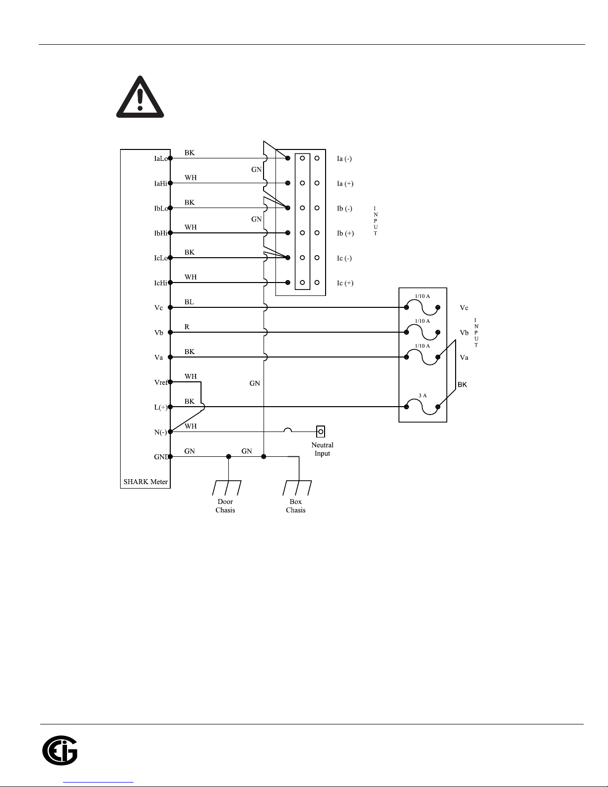
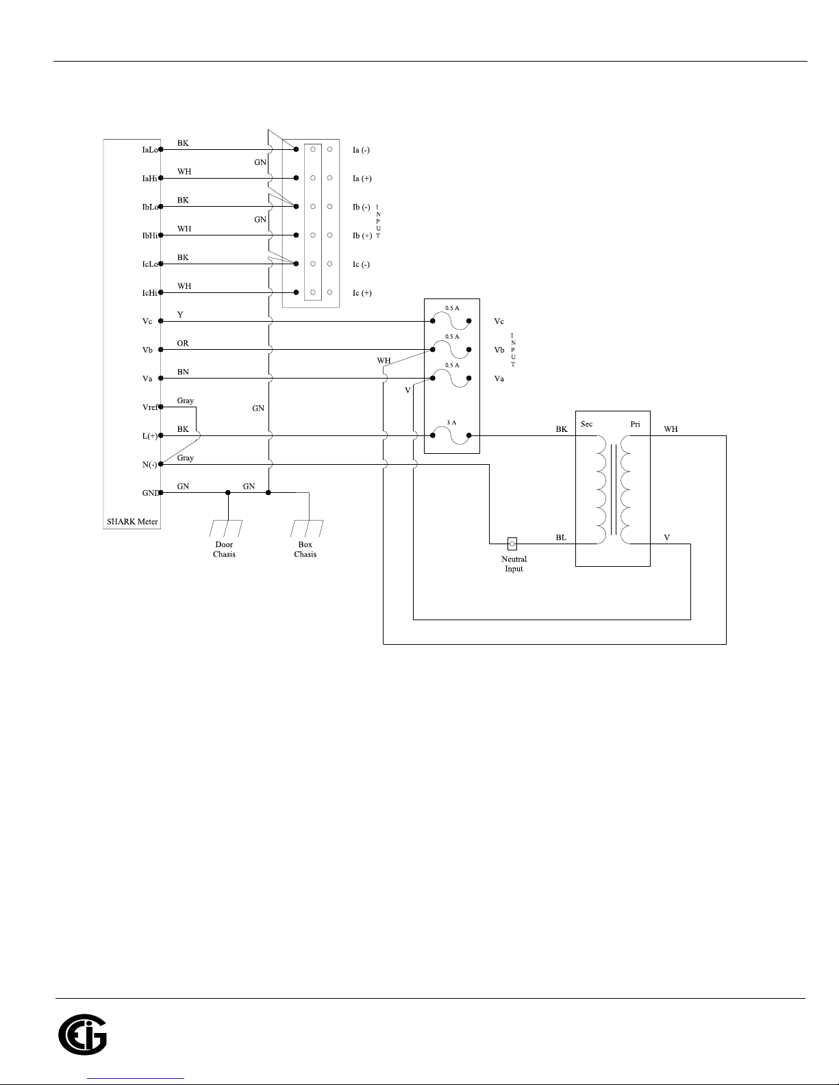
the proper place and all connections are tight. Refer to figures 2.1 and 2.2 for internal
wiring schematics.
WARNING!
Extreme care shall be taken when mounting the enclosure, and making
wire entry holes, to prevent metal chips, filings, and other
contaminants from entering the enclosure which may damage the equipment and
create a hazardous condition.
Doc# E173701 2-1
2: Installation
Electro Industries/GaugeTech
The Leader In Power Monitoring and Smart Grid Solutions
Electro Industries/GaugeTech
The Leader In Power Monitoring and Smart Grid Solutions
AVERTISSEMENT! Attention extrême lors de la monture de l'enceinte
et lors de la mise à terre pour prévenir les articules métalliques, remplissage et autre contaminant de l'entrée de l'enceinte qui peuvent
provoquer une condition dangereuse de l'équipement.
Figure 2.1: 120V Internal Wiring Schematic
Doc# E173701 2-2
2: Installation
Electro Industries/GaugeTech
The Leader In Power Monitoring and Smart Grid Solutions
Electro Industries/GaugeTech
The Leader In Power Monitoring and Smart Grid Solutions
Figure 2.2: 277V Internal Wiring Schematic
Doc# E173701 2-3
2: Installation
Electro Industries/GaugeTech
The Leader In Power Monitoring and Smart Grid Solutions
Electro Industries/GaugeTech
The Leader In Power Monitoring and Smart Grid Solutions
NEMA 1 Enclosure
NEMA 4X Enclosure
2.1: Recommended Procedures for Wire Entry Hole Cutting
The enclosure does not come with wire entry holes (punch entries). They must be cut
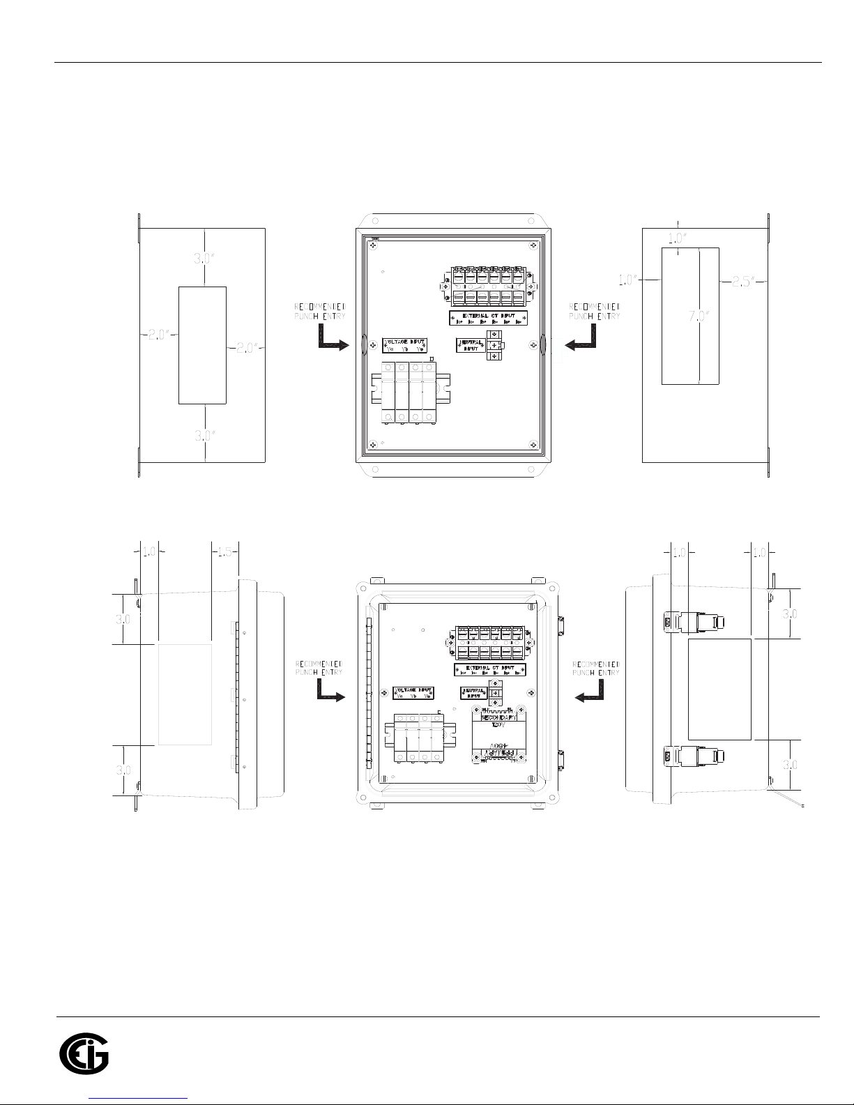
in the location you want depending on the installation. See Figure 2.3 for the locations
that EIG recommends. See CAUTIONS on next page.
Figure 2.3: Location of Recommended Punch Entries
Doc# E173701 2-4
2: Installation
Electro Industries/GaugeTech
The Leader In Power Monitoring and Smart Grid Solutions
Electro Industries/GaugeTech
The Leader In Power Monitoring and Smart Grid Solutions
CAUTIONS!
• There are numerous methods for making wire entry holes in the enclosure but it is
imperative that no loose material generated during the process remains in the
enclosure. During installation and cutting the wire holes, all equipment mounted
inside or on the enclosure shall be protected from loose material.
• No matter what procedure is used the installer shall verify that the hole cutting
process will not damage any of the wiring or components installed inside or on the
enclosure.
The two recommended procedures for cutting the wire entry holes are as follows:
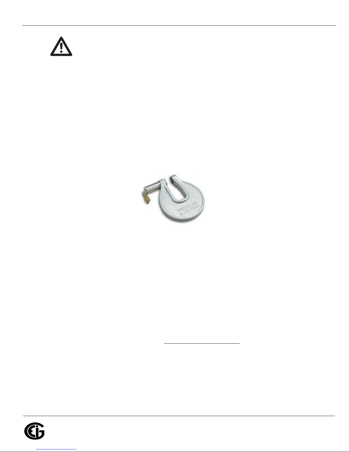
• Use a "C" frame punch to cut the wire entry holes. This type of punch does not
require a pilot hole. A typical "C" frame punch is shown below.
Figure 2.4: “C” Frame Punch
• Regular punch:
1. Place a magnet inside the enclosure where the pilot hole is to be cut and: for
the NEMA 1 enclosure, completely cover the area with masking tape (or other
very sticky tape); for the NEMA 4X enclosure, use sticky tape, only.
2. Drill the pilot hole from the outside and do not let the drill pass more than ¼"
into the enclosure.
3. Remove the tape, magnet, and cuttings and punch the hole.
After wiring and before energizing, vacuum the inside of the enclosure to make sure
that it is free of foreign material. If a vacuum is not available use an alternate method
to clean the inside of the enclosure. Do not use compressed air
(or pressurized gas) to
clean the inside of the enclosure as this may force cuttings into areas that cannot be
seen, creating a hazardous condition.
IMPORTANT!
• All wire entry into the enclosure shall be accomplished with the use of recognized
fittings or strain reliefs. Bare holes shall not be used.
Doc# E173701 2-5
 Loading...