

Electro Industries/GaugeTech Futura+ Series User Manual
User
Manual
• Installation
• Operation
• Programming
Electro Industries/GaugeTech
1800 Shames Drive•Westbury, New York 11590
Tel 516.334.0870•Fax 516.338.4741• www.electroind.com
¯
Multifunction Digital Power Monitor
FUTURA +
SERIES
FUTURA +
SERIES

e
Electro Industries/GaugeTech
FUTURA+ SERIES
Multifunctional Digital Power Monitor
Installation, Operation
and Faceplate Programming Manual
Doc# E100702 Version 4.0 July 31,2008
1800 Shames Drive
Westbury, New York 11590
Tel: (516) 334-0870 z Email: sales@electroind.com
Fax: (516) 338-4741 z Website: www.elect roind.com
Electro Industries/GaugeTech
1800 Shames Drive Westbury, New York 11590 U. S. A
For Customer or Technical Assistance, Repair and Calibration:
Phone: (516) 334-0870 Fax (516) 338-4741
Customer support is available 9:00 A.M. to 4:30 P.M., Eastern Time, Monday through Friday. Please have
the model, serial number and a detailed problem description available. If the problem concerns a particular
reading, please have all meter readings available. When returning any merchandise to E.I.G., a return
authorization number is required.
PRODUCT
WARRANTY
LIMITATION
OF
WARRANTY
STATEMENT
OF
CALIBRATION
DISCLAIMER
COPYRIGHT
©2008 Electro Industries/GaugeTech. All rights reserved. Printed in theUnited States of America.
Electro Industries/GaugeTech warrants this product to be free from defects in material
and workmanship for a period of 4 years from date of shipment. During the warranty
period, we will, at our option, either repair or replace any product that proves to be
defective.
To exercise this warranty, fax or call our customer service department. You will
receive prompt assistance and return instructions. Send the instrument, transportation
prepaid, to the address above. Repairs will be made and the instrument will be
returned.
This warranty does not apply to defects resulting from unauthorized modification,
misuse or use for any reason other than electrical power monitoring. This unit is not to
be used for primary over current protection. Any protection feature in this unit is to be
used for alarm or secondary protection only.
This warranty is in lieu of all other warranties, expressed or implied, including
any implied warranty of merchantability or fitness for a particular purpose.
Electro Industries/GaugeTech shall not be liable for any indirect, special or
consequential damages arising from any authorized or unauthorized use of any
Electro Industries/GaugeTech product.
This instrument has been inspected and tested in accordance with specifications
published by Electro Industries/GaugeTech. The accuracy and calibration of this
instrument are traceable to the National Bureau of Standards through equipment that is
calibrated at planned intervals by comparison to certified standards.
Information presented in this publication has been carefully checked for reliability;
however, no responsibility is assumed for inaccuracies. The information contained in
this document is subject to change without notice.
No part of this manual may be reproduced or transmitted in any form or by any means,
electronic or mechanical, including photocopying, recording, or information storage or
retrieval systems or any future forms of duplication, for any purpose other than the
purchaser's use, without the expressed written permission of Electro
Industries/GaugeTech, division of E. I. Electronics, Inc.

Table of Contents
PART I: INSTALLATION & OPERATION
Chapter 1 AC Power Measurement 1
1.1 Single Phase System 1
1.2 Three-Phase System 2
1.3 Consumption, Demand and Poor Power Factor 3
1.4 Waveform and Harmonics 4
Chapter 2 Mechanical Installation 5
2.1 Explanation of Symbols 5
2.2: Mechanical Installation 5
Chapter 3 Electrical Installation 9
3.1: Important Considerations When Installing Meters 9
3.2 Connecting the Current Circuit 10
3.3 CT Hookup 10
3.4 Connecting the Voltage Circuit 11
3.5 Selecting the Voltage Fuses 11
3.6 Connection to the Main Power Supply 12
3.7 Electrical Connection Installation 12
3.8 Helpful Debugging Tools 16
Chapter 4 Communication Installation 17
4.1 RS232C 17
4.2 RS485 17
4.3 Network of Instruments and Long Distance Communication 23
4.4 Compatible Software (Optional) 23
4.5 Connection Diagram for Modem to EI Device 24
PART II: DISPLAY MODULES
Chapter 5 P14 and P15 Optional Display Overview 27
5.1 Accessing KW, KWD, KWH or KVAR, KVARD, KVARH 27
5.2 Resetting KWD/KWH or KVARD/KVARH 28
5.3 Accessing LM1/LM2 Set Limits for KW/KVAR 29
5.4 LED Test 29
Chapter 6 P31 and P32 Optional Display Overview 31
6.1 Accessing Max/Min Values 31
6.2 Resetting Max/Min Values 32
6.3 Firmware Version/LED Test 33
Chapter 7 P33 Optional Display Overview 35
7.1 Accessing Max/Min Values 35
7.2 Resetting Max/Min Values 36
7.3 Firmware Version/LED Test 37
Chapter 8 P34 Optional Display Overview 39
8.1 Accessing the Power Functions 39
8.2 Accessing Voltage and Current Phases 40
8.3 Accessing %THD Functions 40
8.4 Accessing Max/Min Values 41
8.5 Resetting Values 41
Electro Industries/GaugeTech
i Table of Contents

8.6 Accessing the LM1/LM2 Set Limits 44
8.7 Voltage Phase Reversal and Imbalance 44
8.8 Access Modes 45
8.9 Print Operating Data 45
8.10 Print Programming Data 46
8.11 Firmware Version/LED Test 47
PART III: FACEPLATE PROGRAMMING THE P34 DISPLAY
Chapter 9 Faceplate Programming Overview 49
9.1 General Procedure 49
9.2 Password Entry 50
9.3 Selecting Groups and Functions 51
9.4 Data Entry 52
9.5 Checksum Error—Protective Mechanism 52
9.6 Exiting Programming Mode 53
Chapter 10 Programming Group 0—Global Meter Setup 55
10.1 Group 0, Function 0—Integration Interval 55
10.2 Group 0, Function 1—Meter Address 56
10.3 Group 0, Function 2—Baud Rate 57
10.4 Group 0, Function 3—System Configuration 58
10.4.A Open Delta System Installation Programming 59
10.4.B Switch Communication Protocols 59
10.4.C Printing Option 60
10.5 Group 0, Function 7—Number of Phases 61
Chapter 11 Programming Group 1—Volt, Amp and WATT Full Scale Settings 63
11.1 Group 1, Function 0—Voltage Full Scale 63
11.2 Group 1, Function 1—Amperage Full Scale 65
11.3 Group 1, Function 2—WATTS Scale and Decimal Placement 67
Chapter 12 Programming Group 2—Meter Calibration 69
12.1 Calibration Requirements 69
12.2 Group 2, Functions 0–8—High End Calibration of Voltage Channels, High
and Low End Calibration of Amperage Channels 70
PART IV: OPTIONAL MODULES
Chapter 13 1mA0 and 20mA Analog Output Modules 73
13.1 0–1mA Analog Output Module 73
13.2 4–20mA Analog Output Module 74
13.3 Standard Factory Setup 74
13.4 DC-Output Chart 75
13.5 DC-Output Programming and Calibration 76
13.6 Formulas for DC Output 76
Chapter 14 Relay and Input-Sensing Using the L-100 I/O Module 81
14.1 Input Status Contacts 81
14.2 Internal Relay Activation 83
Chapter 15 Relay and Input-Sensing Using the L-200/L-200 KYZ I/O Modules 85
15.1 Outputs 86
15.2 Sense Inputs 86
Electro Industries/GaugeTech
ii Table of Contents
Part I: Installation & Operation
Θ
Θ
Θ
CHAPTER 1
AC POWER MEASUREMENT
The economics of electric power distribution networking dictate several configurations of AC power
transmission. The number of phases and voltage levels characterize these configurations.
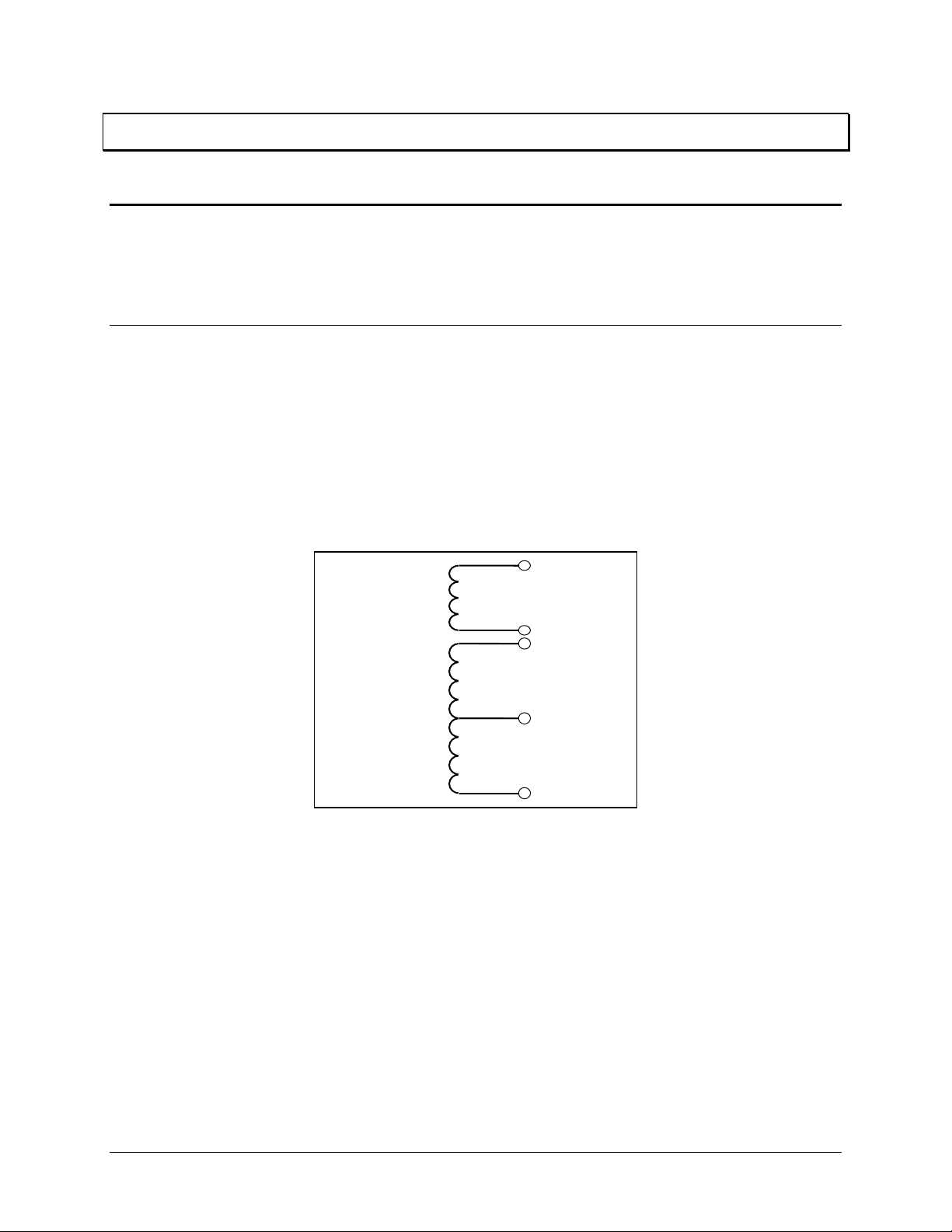
1.1: Single Phase System
A single phase system is a basic two-wire system used in low power distribution applications, such as
residential communities or offices. Typically, the voltage is 120V AC. For higher power requirements,
such as small commercial facilities, the typical power configuration is two lines of 120V AC opposite in
phase (see Figure 1.1 B, below).
This system produces 120 volts from line to neutral for lighting and small appliance use. The line-to-line
voltage is 240V AC, used for higher loads such as water heaters, electric dryers, ranges and machinery.
Line
A)
Single Phase
2 Wires
Neutral
Line 1
B)
Single Phase
3 Wires
Figure 1.1: Single Phase System: (A) Two-Wire, (B) Three-Wire
The power (W) in a single phase system is:
Neutral
Line 2
cos • I • E = W
E = potential, I = current, and cosΘ = phase difference between the potential and the current.
Power in a 120/240V AC system is:
2 Line2 Line1 Line1 Line
Θ
)cos • I • (E + )cos • I • (E = W
Phase differential between the potential and the current results from a non-resistive load, either reactive
or capacitive.
Reactive power (VAR): The additional power consumed that does not produce any work but must be
⋅⋅ insIE=VAR
delivered to the load:
. This is a measure of the inefficiency of the electrical system.
Apparent power (VA): The total power delivered to the load, and the vector sum of real power and
reactive power.
Electro Industries/GaugeTech
1
Chapter 1: AC Power Measurement Futura+ Series
Power Factor (PF): The ratio between real power and apparent power:
PF =
W
VA
=
W
22
WVAR
+
Apparent Power (VA)
Real Power (W)
Figure 1.2: Apparent, Real and Reactive power.
Reactive
Power
(VAR)
Ideal power distribution should have a PF of 1. This condition can be met only if no reactive power
loads exist. In real life applications, many loads are inductive loads. Often, corrective capacitors are
installed to correct Poor Power Factor (see Section 1.3).
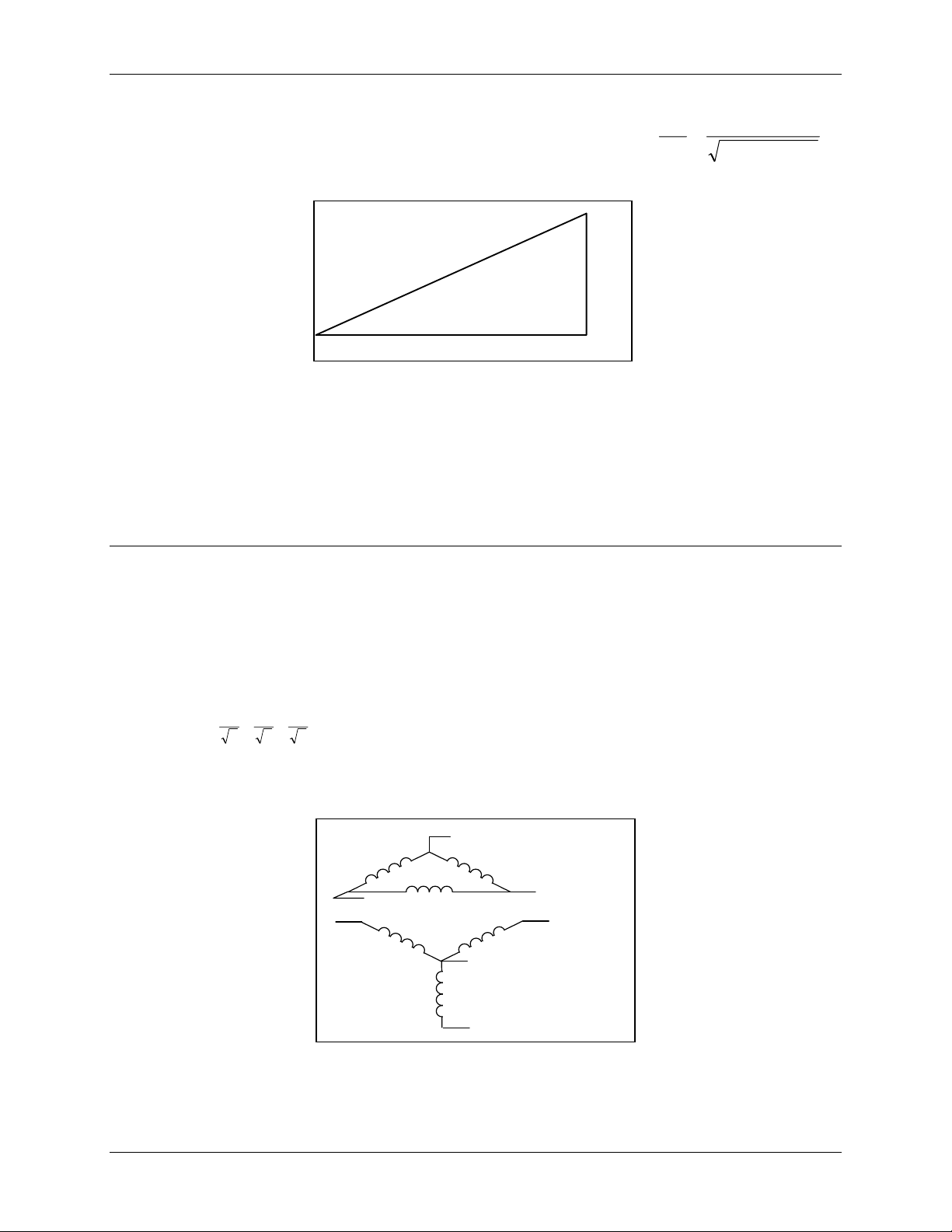
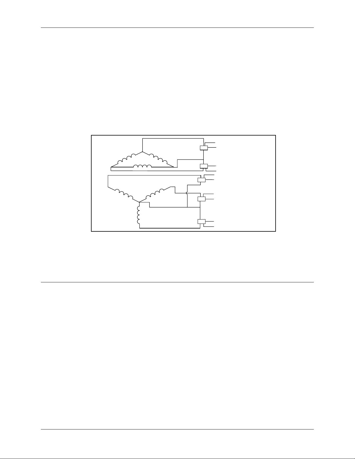
1.2: Three-Phase System
A three-phase system delivers higher levels of power for industrial and commercial applications; the
three phases correspond to three potential lines. A 120° phase shift exists between the three potential
lines.
A typical configuration has either a Delta connection or a Wye connection (see Figure 1.3, below).
In a three-phase system, the voltage levels between the phases and the neutral are uniform and defined
by:
E
E
E
EEE
cnbnan
3
acbcab
=====
3
3
A
C
A
N
C
Figure 1.3: Three-Phase System: (1) Delta, (2) Wye
B
B
2
1) Delta
2) Wye
Electro Industries/GaugeTech
Futura+ Series Chapter 1: AC Power Measurement
A
A
Voltages between the phases vary depending on loading factors and the quality of distribution
transformers. The three-phase system is distributed in different voltage levels: 208V AC, 480V AC, 2400V
AC, 4160V AC, 6900V AC, 13800V AC, and so on.
Power measurement in a poly phase system is governed by Blondel's Theorem. Blondel’s Theorem
states that in a power distribution network which has N conductors, the number of measurement elements
required to determine power is N-1. A typical configuration of poly phase system has either a Delta
connection or a Wye connection (see Figure 1.4, below).
E I
AB A
X
1) Delta
C
2) Wye
B
B
N
C
P = E I
X
X
X
P = E I + E I + E I
X
+ E I
E I
CB C
E I
AN A
E I
BN B
AN
E I
CN C
AB A
CB C
ABC
BN CN
Figure 1.4: Poly Phase System: (1) Delta, (2) Wye
1.3: Consumption, Demand and Poor Power Factor
CONSUMPTION:
The total electric energy usage over a time period is the consumption of WH.
Typically, the unit in which consumption is specified is the kilowatt-hour (KWH): one thousand watts
consumed over one hour. Utilities use the WH equation to determine the overall consumption in a billing
period.
DEMAND: Average energy consumed over a specified time interval. The interval is determined by the
utility, typically 15 or 30 minutes. The utility measures the maximum demand over a billing period.
This measurement exhibits a deviation from average consumption causing the utility to provide
generating capacity to satisfy a high maximum consumption demand. The highest average demand is
retained in the metering system until the demand level is reset.
POOR POWER FACTOR: Results in reactive power consumption. Transferring reactive power over a
distribution network causes energy loss. To force consumers to correct their Power Factor, utilities
monitor reactive power consumption and penalize the user for Poor Power Factor.
T W=WH × W = instantaneous power T = time in hours
Electro Industries/GaugeTech
3
Chapter 1: AC Power Measurement Futura+ Series
⋅
ω
ω
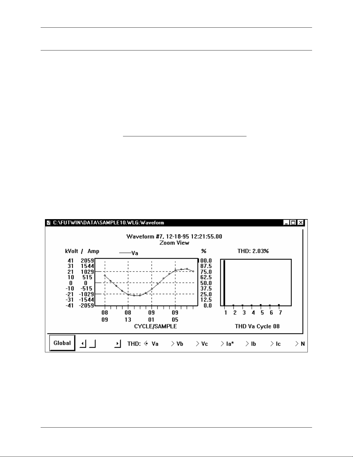
1.4: Waveform and Harmonics
Ideal power distribution has sinusoidal waveforms on voltages and currents. In real-life application s,
where inverters, computers, and motor controls are used, distorted waveforms are generated. These
distortions consist of harmonics of the fundamental frequency.
SINUSOIDAL WAVEFORM:
DISTORTED WAVEFORM:
TOTAL HARMONIC DISTORTION (THD):
=THD of % ×
ω
t)( sin •A
ω
ω
Signal DistortionHarmonic Total of RMS
100
L +t)•sin(•A+t)•sin(•A+t)•sin(•A+t) •sin( •A
332211
Signal lFundamenta the of RMS
HARMONIC DISTORTION: A destructive force in power distribution systems. It creates safety problems,
shortens the life span of distribution transformers, and interferes with the operation of electronic devices.
The Futura+ monitors the harmonic distortion to the 31st harmonic. A waveform capture of distorted
waveform is also available.
% THD GRAPH
4
Electro Industries/GaugeTech
CHAPTER 2
MECHANICAL INSTALLATION
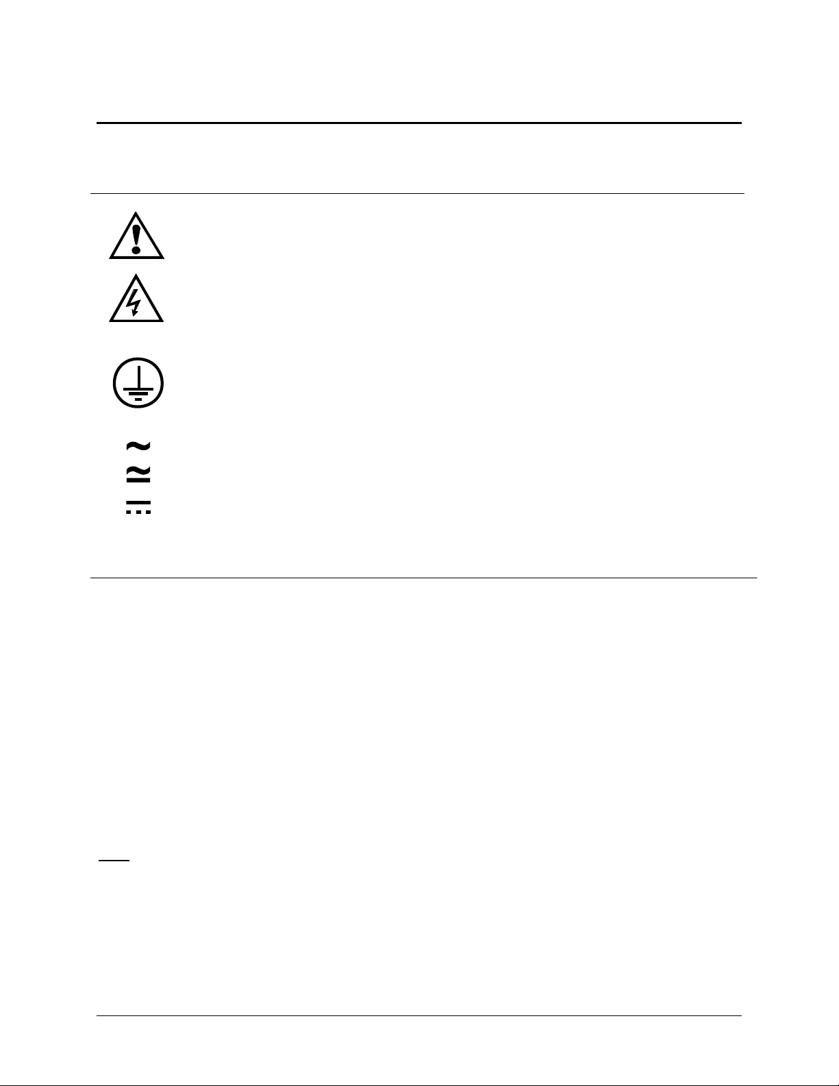
2.1: Explanation of Symbols:
CAUTION, RISK OF DANGER. DOCUMENTATION MUST BE CONSULTED IN ALL
CASES WHERE THIS SYMBOL IS MARKED.
CAUTION, RISK OF ELECTRIC SHOCK.
PROTECTIVE CONDUCTOR TERMINAL.
ALTERNATING CURRENT.
BOTH DIRECT AND ALTERNATING CURRENT.
DIRECT CURRENT.
2.2: Mechanical Installation
METER NOTES:
• To clean the meter, wipe it with a clean, dry cloth.
• Meter’s environmental conditions:
- Operating Temperature: -20
- Storage Temperature: -30
- Relative Humidity: 90% non-condensing
- Ventilation requirement: Natural convection cooling is adequate. Allow unobstructed
airflow around the unit and monitor for a rise in temperature when the meter is installed in
an enclosed cabinet.
- The meter has no specific protection against ingress of water.
- The rating of this meter requires all input and output terminals to be connected
permanently: modification and maintenance of any kind should be performed only by
qualified personnel.
- Rated Altitude: 2,000 meters maximum
Note: Figures in this chapter are not to scale.
o
C to +70oC/-4.0oF to +158oF
o
C to +80oC/-22oF to +176oF
Electro Industries/GaugeTech
5

Chapter 2: Mechanical Installation Futura+ Series
2 FEET
OF DISPLAY CABLE
SUPPLIED
1.6875
RECOMMENDED CUTOUT
.200
DIA.
(4)
DISPLAY MODULE
Industries
Electro
.400
.60 DIA.
DISPLAY CABLE OPENING
3.375
SQ.
3.375
SQ.
AMPS - A-
VOLTS
SCAN
% OF
T.H.D.
AMPS
SCAN
MAX
MIN
4.375
SQ.
POWER
SCAN
LIMITS
PHASE
NEXT
OVR.LMT
PRT/PRO
.890
Diagram 2.1A: Recommended cutout for CPU-1000 display module—measurements in inches
5.00
•
Recommended mounting screw size is #8.
•
6.00
Extra deep slots permit use of existing
screw locations if upgrading from an earlier
slot base.
Diagram 2.1B: Recommended cutout for the CPU-1000 transducer module
6
Electro Industries/GaugeTech
Futura+ Series Chapter 2: Mechanical Installation
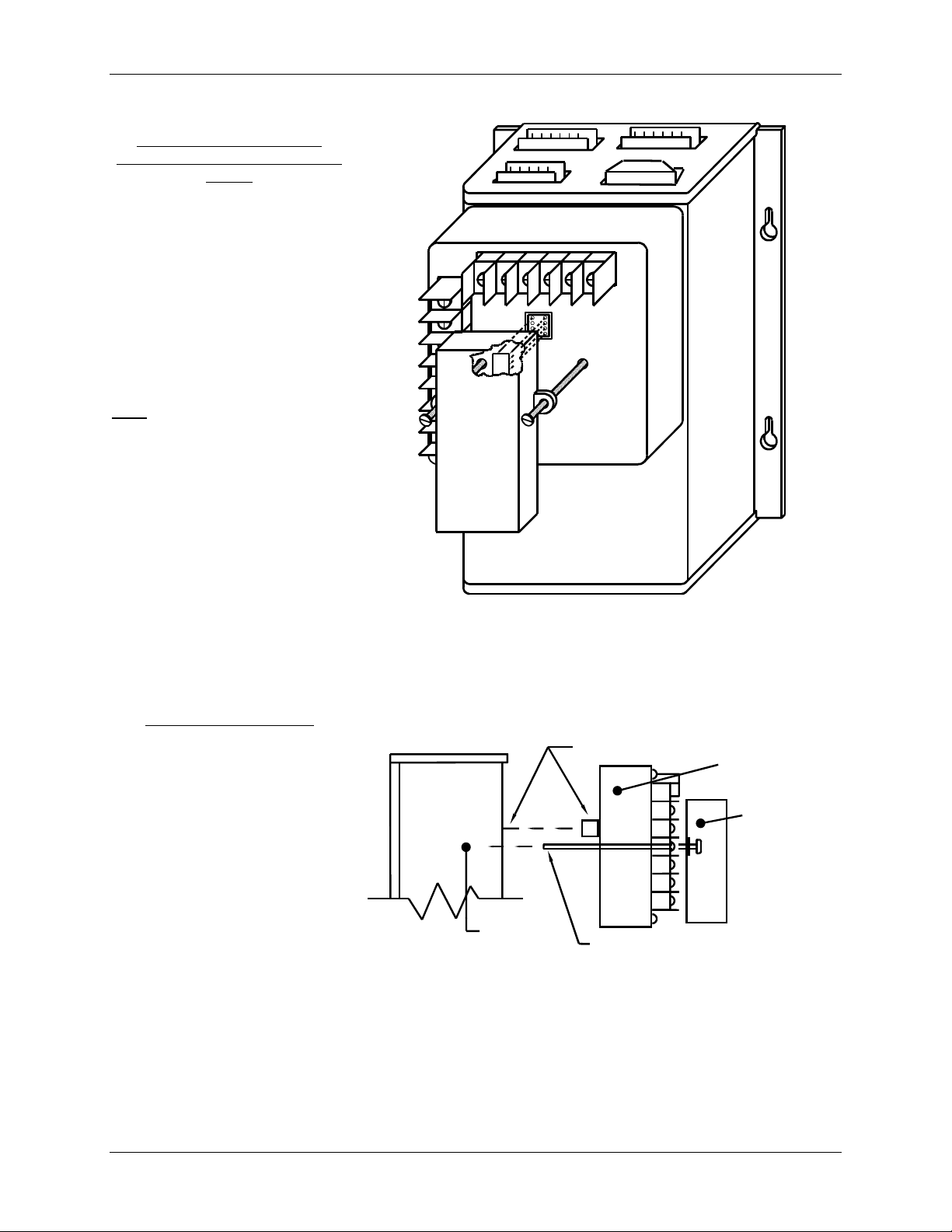
Installation of RS232C/485
Communication Converter or DC
Output
• Use the two screws as guides
and insert them into the
respective holes.
• Slowly lower the converter.
• The eight pins (on the
converter) mount into the
socket.
: When mounting the
Note
communication
converter, be careful—
the pins bend easily.
Installation of CPU-1000
(This installation is usually
performed at the factory. It is
included here in case the input
module is upgraded.)
• Connect the input module to
the transducer base unit.
• Follow the instructions for
installing the communication
converter (if this option was
ordered).
• For an extension, use the
electrical extension converter
(EEC) that accommodates
several remote displays or a
single display.
Diagram 2.2: RS232C/485 Communication Converter or DC Output
Installation (both are optional)
SIDE VIEW
FIRST PUT (16) PIN
FUTURA+
MODULE
CONNECTOR TOGETHER.
(2) 8-32 SCRE W S WILL
LINE UP WITH 2 PEMS
ON THE TRANSDUCER COVER.
INPUT
MODULE
COMMUN ICATION
MODULE
Diagram 2.3: Standard Installation of the CPU-1000
Electro Industries/GaugeTech
7

Chapter 2: Mechanical Installation Futura+ Series
MULTI-FUNCTION
DISPLAY MODULES
Electro Industries
4.375"
AC KILOW AT S
MODE ADV.
SET
P-14/15 P-31
AC VOL TS
MAX
MIN
LM1
LM2
MAX/MIN
L-N
LIMITS
L-L
PRINT
PROG
A-N
A-B
B-N
B-C
C-N
C-A
SET
P-32 P-34
SQ.
Electro Industries
MAX
MIN
LM1
LM2
THD
MAX/MIN
LIMITS
VOLTS
AMPS POW ER
AC AMPERES
MAX
MIN
LM1
LM2
MAX/MIN
PRINT
C
LIMITS
PROG
N
AC VOLTS
ANBNCNABBCC
A
AC AMPS
NCBA
POWER
PF
KW
KVA
KVAR
FREQKWHKVAH
PHASE
NEXT
A
B
C
N
SET
1.5"
4.5"
COLOR-CODE ASSIGNMENTS FOR J1-1/J1-2
FRONT VIEW OF J1-1/J1-2
2
1
3456
J1-1
J1-2
3.75"
J1-2
J2-2 (RS485)
J1-1
J2-1 (RS232)
6.0"
SQ.
SF-485
PIN 1- BLACK
PIN 2- RED
PIN 3- ORANGE
PIN 4- BLUE
PIN 5- GREEN
PIN 6- WHITE
6.0"
8.0"
4.625"
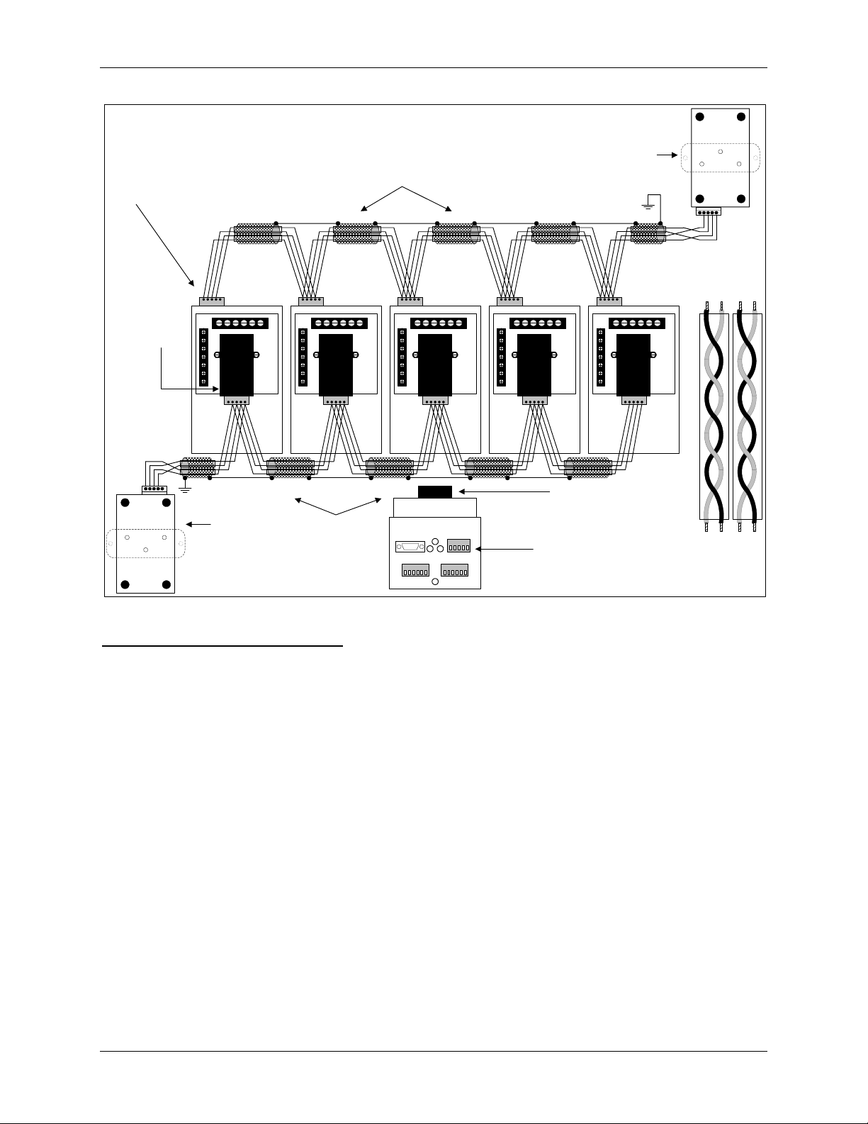
Diagram 2.4: Standard Installation with electrical extension connector. Displays ar e optional.
Note: A maximum of 4 displays connect to either J1-1 or J1-2 or both without external power
supply. A maximum of 16 displays connect with external power supply (optional). The
displays are powered by a 4-wire RS485 with a power and ground wire. For longer
distances, the wires should be shielded and grounded at one point only
.
8
Electro Industries/GaugeTech

CHAPTER 3
ELECTRICAL INSTALLATION
3.1: Important Considerations When Installing Meters
Please read the following sections carefully for important safety information regarding
installation and hookup of the meter.
This meter is rated as “permanently installed equipment” and must be installed in non-accessible
areas only, e.g. control panels, switchgear enclosures, etc.
Installation of the meter must be performed only by qualified personnel who follow standard
safety precautions during all procedures. Those personnel should have appropriate
training and experience with high voltage devices. Appropriate safety gloves, safety glasses and
protective clothing are recommended.
During normal operation of the meter, dangerous voltages flow through many parts of the meter,
including: Terminals and any connected CTs (Current Transform ers) and PTs (Potential
Transformers), all I/O Modules (Inputs and Outputs) and their circuits. All Primary and Secondary
circuits can, at times, produce lethal voltages and currents. Avoid contact with any currentcarrying surfaces.
Do not use the meter for primary protection or in an energy-limiting capacity. The meter can only
be used as secondary protection. Do not use the meter for applications where failure of the
meter may cause harm or death. Do not use the meter for any application where there may be a
risk of fire.
All meter terminals should be inaccessible after installation.
Do not apply more than the maximum voltage the meter or any attached device can withstand.
Refer to meter and/or device labels and to the Specifications for all devices before applying
voltages. Do not HIPOT/Dielectric test any Outputs, Inputs or Communications terminals.
EIG recommends the use of Shorting Blocks and Fuses for voltage leads and power supply to
prevent hazardous voltage conditions or damage to CTs, if the meter needs to be removed from
service. CT grounding is optional.
The UL Measurement Category of the meter is Category III, Pollution Degree II.
Refer to additional safety notes on the next page.
Electro Industries/GaugeTech
9

Chapter 3: Electrical Installation Futura+ Series
NOTES
:
IF THE EQUIPMENT IS USED IN A MANNER NOT SPECIFIED BY THE MANUFACTURER,
THE PROTECTION PROVIDED BY THE EQUIPMENT MAY BE IMPAIRED.
THERE IS NO REQUIRED PREVENTIVE MAINTENANCE OR INSPECTION NECESSARY FOR
SAFETY. HOWEVER, ANY REPAIR OR MAINTENANCE SHOULD BE PERFORMED BY THE
FACTORY.
DISCONNECT DEVICE
: THE FOLLOWING PART IS CONSIDERED THE EQUIPMENT
DISCONNECTING DEVICE. A SWITCH OR CIRCUIT-BREAKER SHALL BE INCLUDED IN THE
END-USE EQUIPMENT OR BUILDING INSTALLATION. THE SWITCH SHALL BE IN CLOSE
PROXIMITY TO THEEQUIPMENT AND WITHIN EASY REACH OF THE OPERATOR. THE
SWITCH SHALLBE MARKED AS THE DISCONNECTING DEVICE FOR THE EQUIPMENT.
3.1.1: Measurement Inputs Rating:
UL Classification: Measurement Category III, Pollution Degree II.
Current Inputs: 10A max.
Voltage Inputs
Frequency: (45 to 75) Hz
1
: 150V L-N, 300V L-L
1
Suffix - G extends the maximum direct voltage to 300V phase to neutral, 600 volt phase to phase.
Models with suffix - G are not UL rated.
3.2: Connecting the Current Circuit
Install the cable for the current at 600V AC minimum. The cable connector should be rated at 6 Amps or
greater and have a cross-sectional area of 16 AWG.
Mount the current transformers (CTs) as close as possible to the meter. The table below illustrates the
maximum recommended distances for various CT sizes, assuming the connection is via 16 AWG cable.
CT Size (VA) Maximum Distance (CT to CPU1000)
2.5 VA 10 FEET
5.0 VA 15 FEET
7.5 VA 30 FEET
10.0 VA 40 FEET
15.0 VA 60 FEET
30.0 VA 120 FEET
WARNING: DO NOT leave the secondary of the CT open when primary current is flowing. This
may cause high voltage, which will overheat the CT. If the CT is not connected, provide
a shorting block on the secondary of the CT.
3.3: CT Connection
If the CPU-1000 is connected directly, maintain the exact connection to avoid incorrect polarity.
It is important to maintain the correct CT polarities when using CTs to connect the CPU-1000. CT
polarities are dependent upon correct connections of CT leads and the directio n the CTs are facing when
10
Electro Industries/GaugeTech

Futura+ Series Chapter 3: Electrical Installation
clamped around conductors. The dot on the CT must face the line side and the corresponding secondary
connection must connect to the appropriate pin. Failure to connect CTs properly results in incorrect Watt
readings.
3.4: Connecting the Voltage Circuit
For proper meter operation, the voltage connection must be maintained. The voltage must correspond to
the correct terminal.
The cable required to terminate the voltage sense circuit should have an insulation rating greater than
600V AC and a current rating greater than 0.1 A.
3.5: Selecting the Voltage Fuses
We recommend using fuses, although the connection diagrams on the following pages do not show them.
Use a 1 Amp fuse on each voltage input.
Electro Industries/GaugeTech
11
Chapter 3: Electrical Installation Futura+ Series
3.5: Connection to the Main Power Supply
The CPU-1000 requires a separate power supply. Listed below are the four power supply options and
their corresponding suffixes. The maximum power consumption is 12VA or 9W. AC unit’s frequency rating
is 50/60Hz.
CONTROL
POWER OPTION SUFFIX
115V AC 115A
230V AC/DC 230A
24-48V DC D
125V AC/DC (UNIVERSAL) D2
: Do not ground the unit through the negative of the DC supply. Separate grounding is
Note
required.
Note
: Externally fuse power supply with a slow-blow 3 Amp fuse.
3.6: Electrical Connection Installation
Choose the diagram that best suits your application and maintain the polarity. Follow the outlined
procedure to verify correct connection.
Connection Diagrams
—If the connection diagram you need is not listed,
contact EIG for a custom connection diagram.
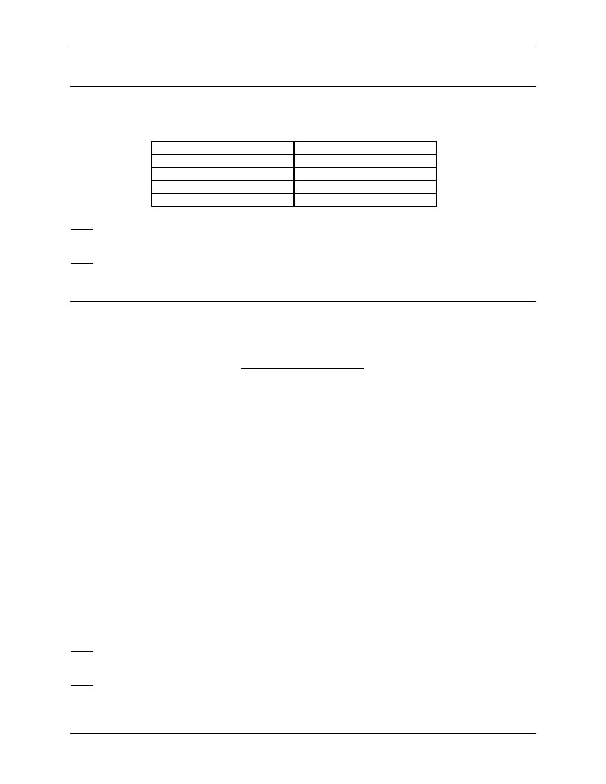
I. Three-Phase, Three-Wire System Delta with Direct Voltage and CTs
II. Three-Phase, Three-Wire Open Delta with two CTs and two PTs
—Open Delta System Installation should only be used if the electrical system is a 3-wire OPEN
DELTA. (The P-34 display can enable or disable Open Delta in the faceplate programming
mode: Group 0, Function 3, Pack 1, Switch D; see Chapter 10.)
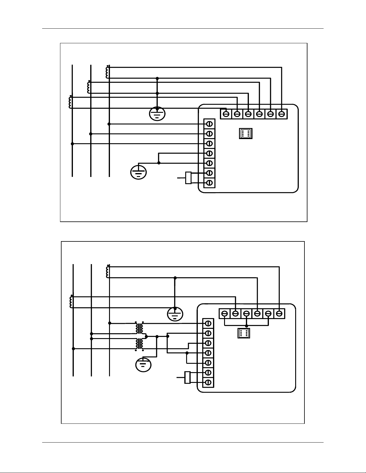
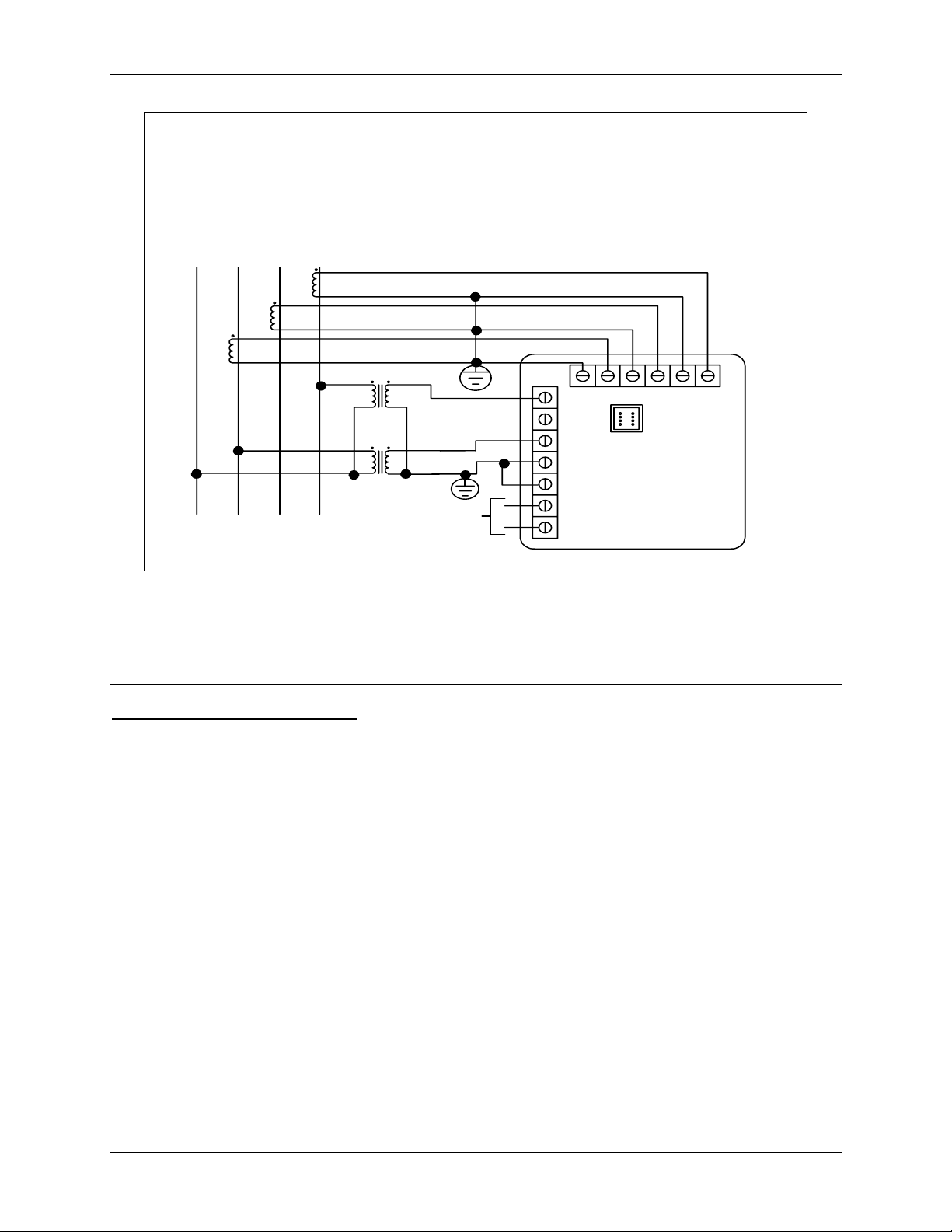
III. Three-Phase, Three-Wire Open Delta with three CTs and two PTs
—Open Delta System Installation should only be used if the electrical system is a 3-wire OPEN
DELTA. (The P-34 display can enable or disable Open Delta in the faceplate programming
mode: Group 0, Function 3, Pack 1, Switch D; see Chapter 10.)
IV. Three-Phase, Four-Wire System Wye with Direct Voltage and CTs
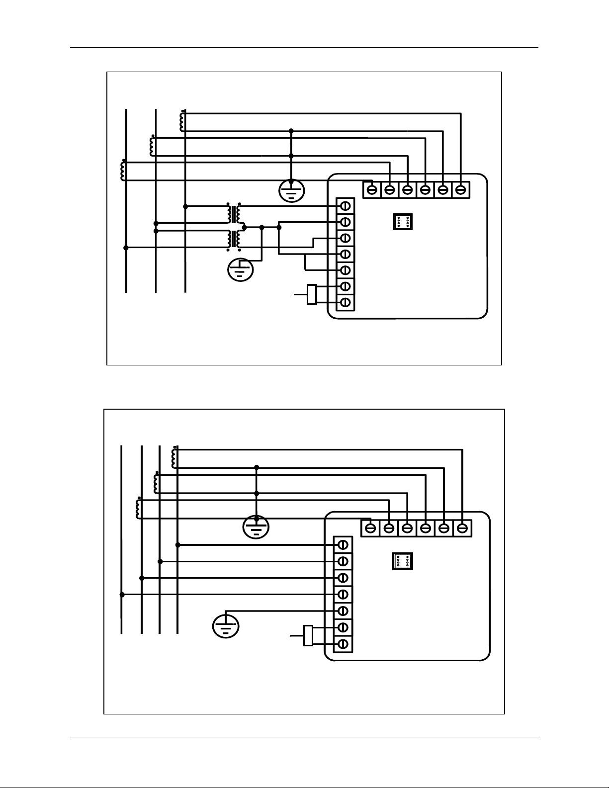
V. Three-Phase, Four-Wire System Wye with CTs and PTs
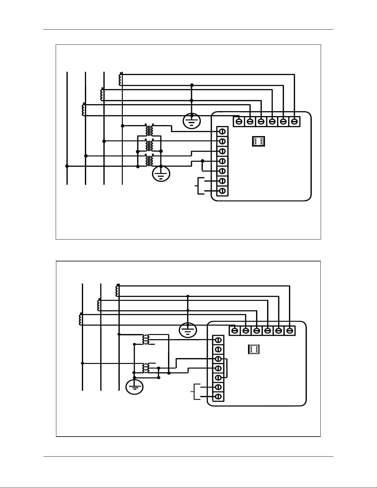
VI. Broken Delta System
VII. Three-Phase, Four-Wire Wye with 2.5 Element
Note
: For P-34 display—see phase reversal (Chapter 8) if a message of CBA appears after
installation.
Note
: Control power polarity indications only apply if DC control power was ordered.
12
Electro Industries/GaugeTech
Futura+ Series Chapter 3: Electrical Installation
LINE
A
BC
LOAD
POWER
+
-
BACK VIEW
8
7
6
5
4
3
2
1
9
PORT
L1
L
10
11 12
13
I. Three-Phase, Three-Wire System Delta with Direct Voltage and CTs
LINE
A
LOAD
BC
POWER
+
-
BACK VIEW
8
9
7
6
5
4
3
2
L1
1
L
II. Three-Phase, Three-Wire Open Delta with two CTs and two PTs
—Special programming required: see note, page 9
10
PORT
11 12
13
Electro Industries/GaugeTech
13
Chapter 3: Electrical Installation Futura+ Series
A
LINE
BC
LOAD
POWER
+
-
BACK VIEW
8
7
6
5
4
3
2
L1
1
L
9
PORT
10
11 12
13
III. Three-Phase, Three-Wire Open Delta with three CTs and two PTs
—Special programming required, see note page 9
LINE
NA
LOAD
BC
POWER
+
-
BACK VIEW
8
7
6
5
4
3
L1
2
L
1
9
PORT
10 11
IV. Three-Phase, Four-Wire Wye with Direct Voltage and CTs
12 13
14
Electro Industries/GaugeTech
Futura+ Series Chapter 3: Electrical Installation
LINE
NA
BC
BACK VIEW
LOAD
POWER
8
910
7
6
5
4
3
+
-
2
1
PORT
L1
L
11
12 13
V. Three-Phase, Four-Wire System WYE with CTs and PTs
LINE
A
BC
BACK VIEW
LOAD
VI. Broken Delta System with CTs and PTs, Option E
Note: This option must be custom ordered from the factory.
Electro Industries/GaugeTech
2x
3x
1
2
G
1
POWER
+
-
8
910
7
6
5
PORT
4
3
2
L1
1
L
11
12 13
15
Chapter 3: Electrical Installation Futura+ Series
LINE
NA
LOAD
BC
CONTROL
POWER
+
-
BACK VIEW
8
910
7
6
PORT
5
4
3
2
L1
1
L
11
12 13
VII. Three-Phase Four-Wire WYE with 2.5 Element
Note: This option must be ordered from the factory.
3.7: Helpful Debugging Tools
Isolating a CT Connection Reversal
1. Remove potential connections to terminals 6 and 7. Observe the KW reading. It should be positive. If
negative, reverse the CT wires on terminals 8 and 9.
2. Connect terminal number 6 potential. If KW decreases to about zero, reverse CT wires on terminals 10
and 11.
3. Connect terminal number 7 potential. If KW is one-third of the expected reading, reverse CT wires to
terminals 12 and 13.
16
Electro Industries/GaugeTech
CHAPTER 4
A
COMMUNICATION INSTALLATION
All CPU-1000 instruments can be equipped with the RS232C or the RS485.
• Use the Top Port for MODBUS, DNP, RTU and ASCII protocols (see Figure 4.1, below).
• Use the Main Port for Futura+ Communicator protocols (see Figure 4.1, below).
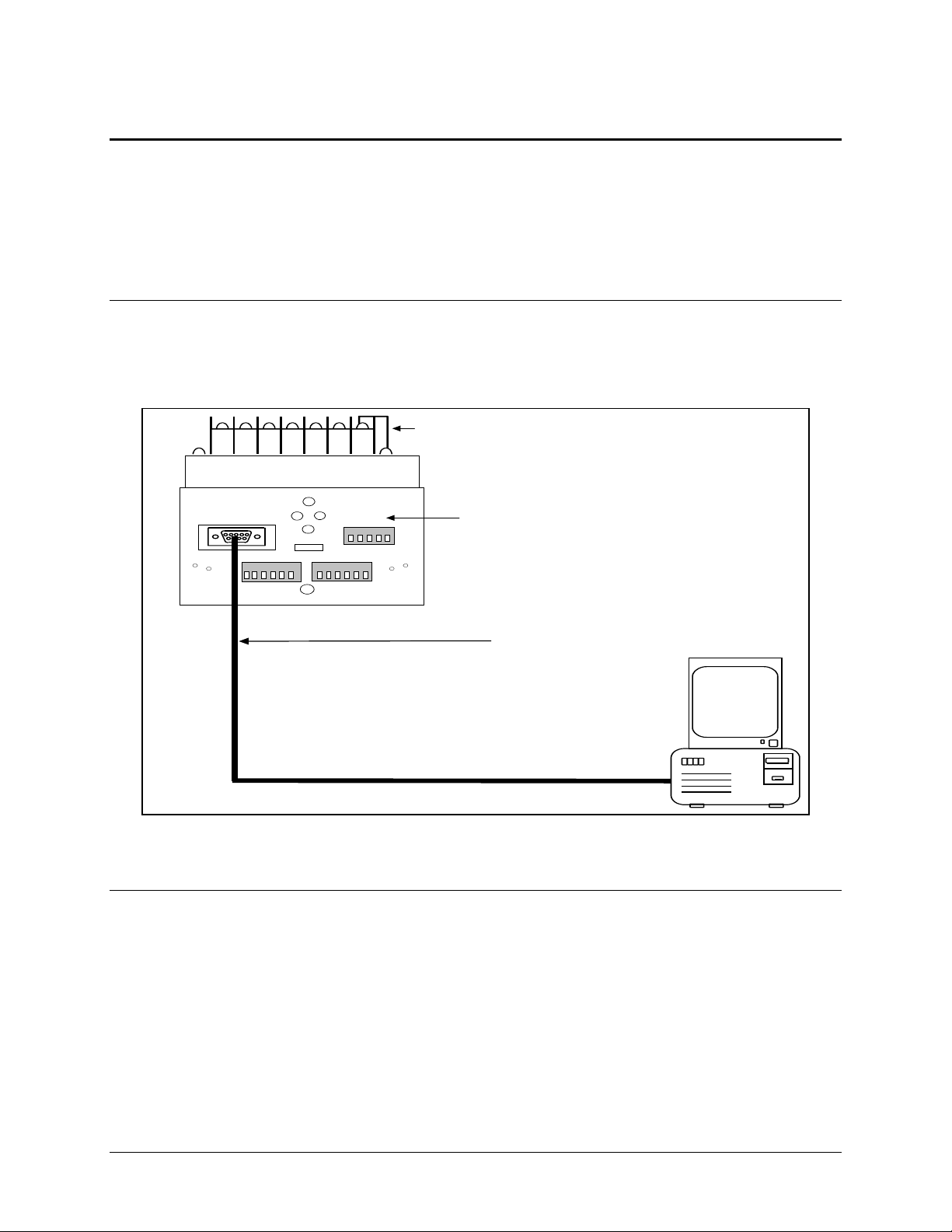
4.1: RS232C
RS232C communication is used to link a single CPU-1000 instrument with a computer or device su ch as
RTU or PLC. The link is capable for a distance up to 100 feet. A standard 9-pin female serial port allows
direct connection to a computer with a 9-pin cable.
TOP PORT
M A IN P O R T
US E A 232 EX TE NSION CAB LE
DIRECT PIN-TO-PIN CA BLE CAN BE USED.
NO NULL-MODEM IS REQUIRED.
RS -232C CO M M U N IC AT ION
Figure 4.1: RS232C Communication Connection Installation
4.2: RS485
RS485 parallels multiple instruments on the same link. Its operating capability is up to 4000 feet. When
using only 2 wires (on the RS485), the link can include up to 15 instruments (see Figure 4.5). When using
all 4 wires, the link can include up to 31 instruments (see Figure 4.2).
Each CPU-1000 instrument has a unique address up to four digits long. This allows the user to
communicate with up to 10,000 instruments. Available standard baud rates are 1200, 2400, 4800, and
9600. To select the proper baud rate, apply the following rules:
• The Top port should always be operated at 9600 baud max.
• Maximum baud rate is 38400 for the Main port.
• For a smaller number of instruments over a long distance, use a lower baud rate.
• Optimal recommended baud rate is 1200 baud if noisy conditions exist.
Electro Industries/GaugeTech
17
Chapter 4: Communication Installation Futura+ Series
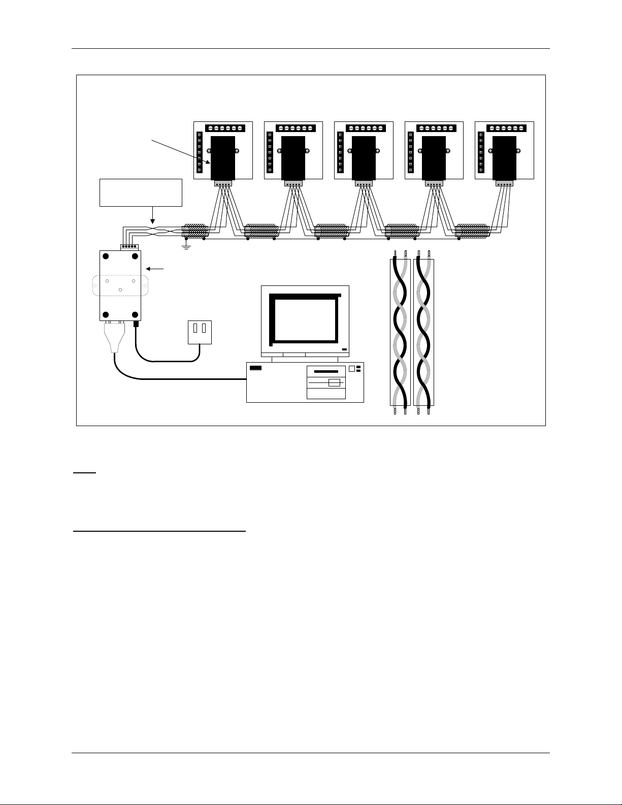
RS485 Hookup Diagram (4 wire) Full Duplex
SF485DB
(Top Port)
This does not represent a
twisted pair. It shows the crossover from R to T between the
Unicom and the rest of the bus
RS-485
Electro Industries
UNICOM 2500
(Bottom View Shown)
RS-232
IBM Compatible
T+ T-R-R+
Figure 4.2: 4-Wire RS485 Communication Connection Installation Full D uplex
—Detail View next page
Note
: 4-wire RS485 is strongly recommended because it provides cleaner communication and is
less susceptible to noise interference. It is important to shield the communication wire and
ground it at one end. Grounding at both ends causes a ground loop and results in noise
problems.
Connecting 4-Wire bus to RS485 Port:
• Connect the T- wire of the Unicom 2500 to the R- on the RS485 port
• Connect the R- wire of the Unicom 2500 to the T- on the RS485 port
• Connect the T+ wire of the Unicom 2500 to the R+ on the RS485 port
• Connect the R+ wire of the Unicom 2500 to the T+ on the RS485 port
18
Electro Industries/GaugeTech
Futura+ Series Chapter 4: Communication Installation
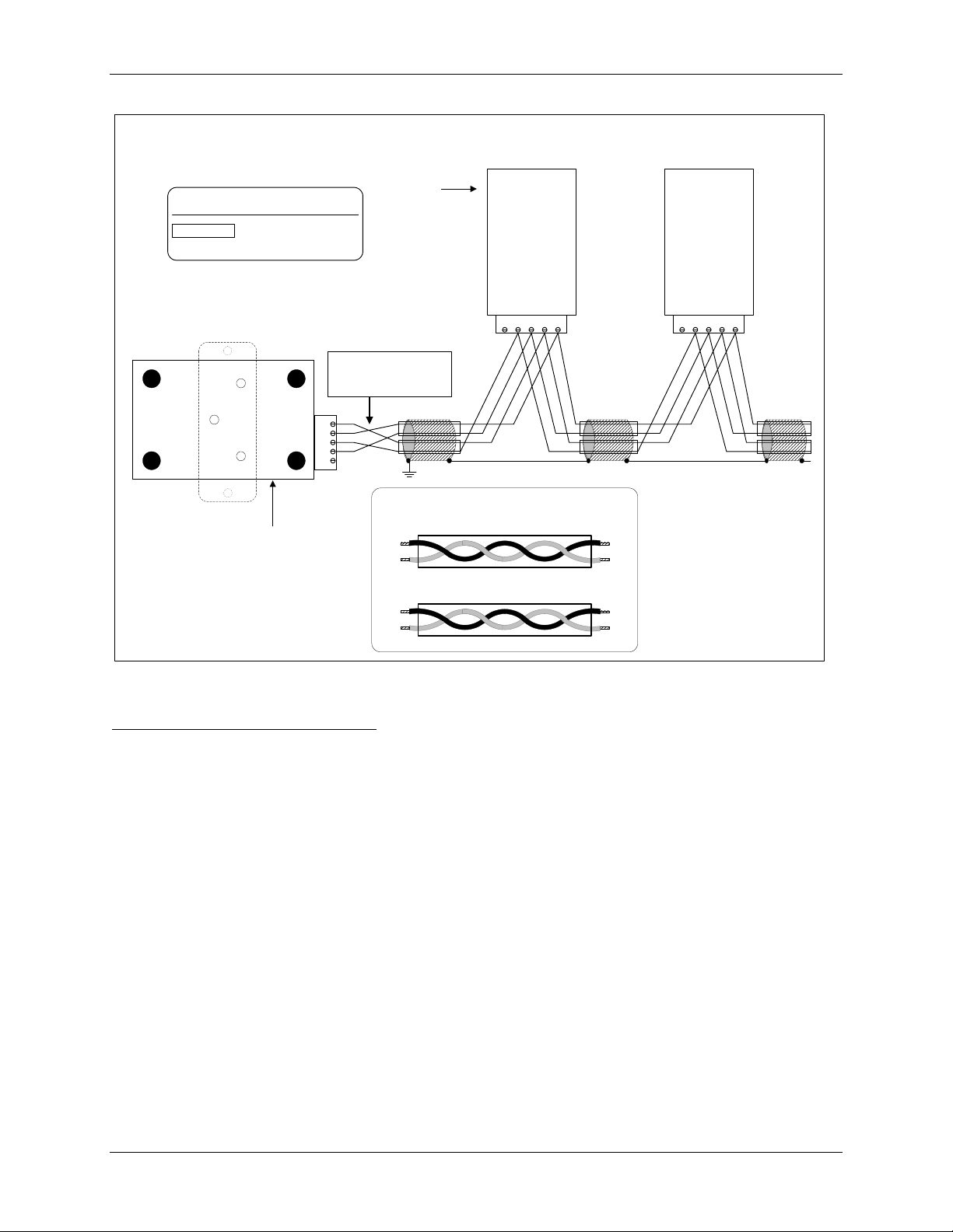
RS485 Hookup Diagram (4 wire) Full Duplex Detail view
RS-232
Electro Industries
UNICOM 2500
(Bottom View Shown)
Key
Twisted Pair Segment
This does not represent a
twisted pair. It shows the crossover from R to T between the
Unicom and the rest of the bus
RS-485
TR-
T+
R+
Gnd
Top Port
RS485
Communications
Port
Model#
SF485DB
GR+T+R-T- GR+T+R-T-
Enlarged view of twisted pair segments
R- R+
Receive Pair
Transmit Pair
T+T-
RS485
Communications
Port
Model#
SF485DB
R-R+
T+ T-
Figure 4.3: 4-Wire RS485 Communication Connection Installation Full Duplex Detail View
Connecting 4-Wire bus to RS485 Port:
• Connect the T- wire of the Unicom 2500 to the R- on the RS485 port
• Connect the R- wire of the Unicom 2500 to the T- on the RS485 port
• Connect the T+ wire of the Unicom 2500 to the R+ on the RS485 port
• Connect the R+ wire of the Unicom 2500 to the T+ on the RS485 port
Electro Industries/GaugeTech
19
Chapter 4: Communication Installation Futura+ Series
RS-232
RS485 Hookup Diagram (4 wire) Full Duplex
Shield
Main Port
Top Port
RS-485
Electro Industries
UNICOM 2500
(Bottom View Shown)
Shield
Main Port J2-2 (RS485)
Electro Industries
(Bottom View Shown)
Top Port
UNICOM 2500
RS-485
J2-2 (RS-485)J2-2 (RS-485)J2-2 (RS-485)J2-2 (RS-485)J2-2 (RS-485)
T+ T-R-R+
RS-232
Figure 4.4: 4-Wire RS485 Communication Connection Installation Full Duplex for Top and Main Ports
Connecting 4-Wire bus to RS485 Port:
• Connect the T- wire of the Unicom 2500 to the R- on the RS485 port
• Connect the R- wire of the Unicom 2500 to the T- on the RS485 port
• Connect the T+ wire of the Unicom 2500 to the R+ on the RS485 port
• Connect the R+ wire of the Unicom 2500 to the T+ on the RS485 port
20
Electro Industries/GaugeTech
Futura+ Series Chapter 4: Communication Installation
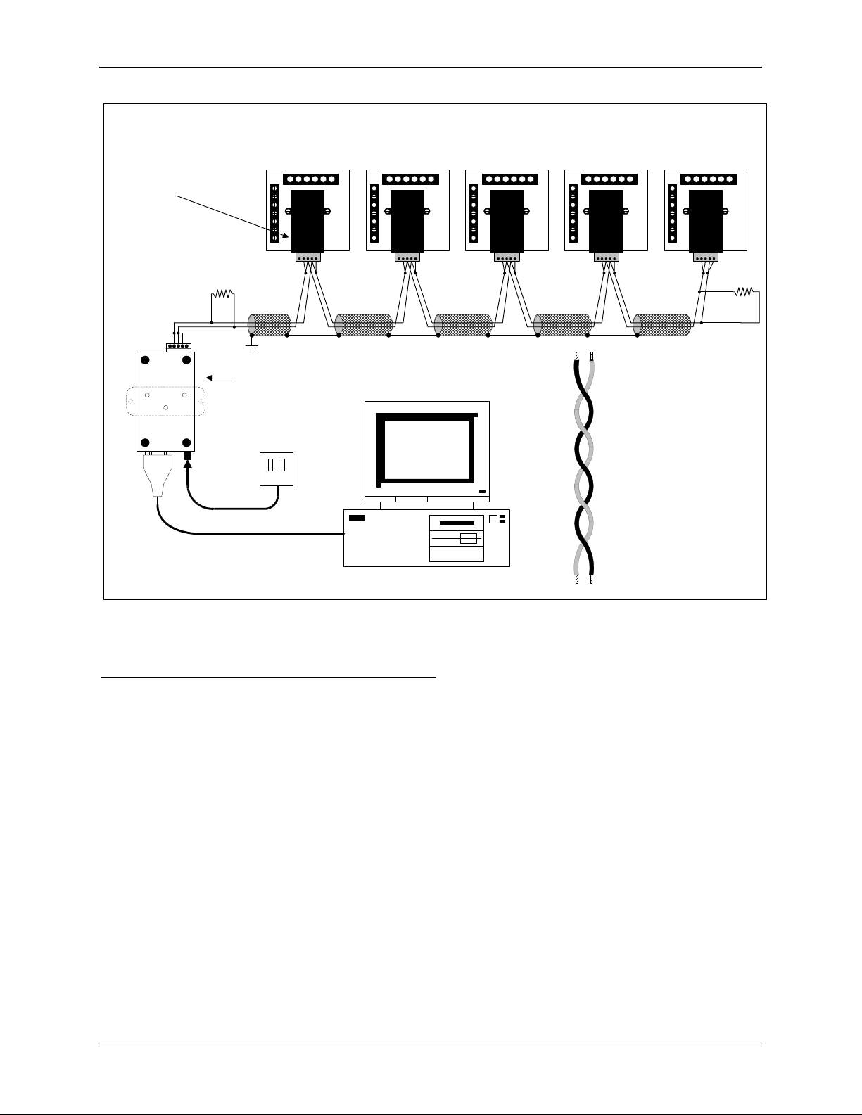
RS485 Hookup Diagram (2 wire) Half Duplex
SF485DB
(Top Port)
R
T
RS-485
RS-232
R
T
Electro Industries
UNICOM 2500
(Bottom View Shown)
IBM Compatible
Figure 4.5: 2-Wire RS485 Communication Connection Installation Half Duplex for Top Port
—Detail view on following page
Connecting two wire bus to RS485 Port on CPU-1000
Take the positive (+) wire and connect to R+ on the RS485 Port.
Connect a jumper from R+ to T+ on the RS485 Port.
Take the negative (-) wire and connect to R- on the RS485 Port.
Connect a jumper from R- to T-.on the RS485 Port.
(-)(+)
Electro Industries/GaugeTech
21
Chapter 4: Communication Installation Futura+ Series
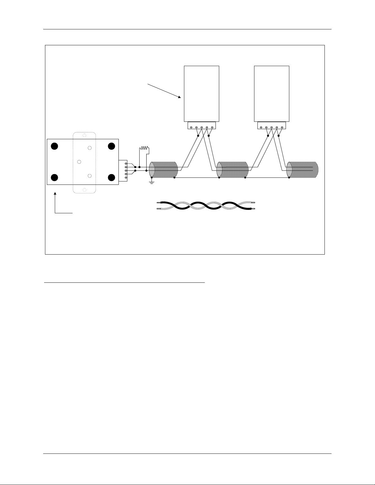
RS485 Hookup Diagram (2 wire) Half Duplex Detail View
RS-485
Communications
Port
Model#
SF485DB
GR+T+R-T- GR+T+R-T-
RS-232
RS-485
T+
R+
Gnd
TR-
Top Port
R
T
(-) (+)
Electro Industries
UNICOM 2500
(Bottom View Shown)
Figure 4.6: 2-Wire RS485 Communication Connection Installation Half Duplex Detail View
Connecting two wire BUS to Top Port RS485 on CPU-1000
• Take the positive (+) wire and connect to R+ on the RS485 Port.
• Connect a jumper from R+ to T+ on the RS485 Port.
• Take the negative (-) wire and connect to R- on the RS485 Port.
• Connect a jumper from R- to T-.on the RS485 Port.
RS-485
Communications
Port
Model#
SF485DB
22
Electro Industries/GaugeTech
Futura+ Series Chapter 4: Communication Installation
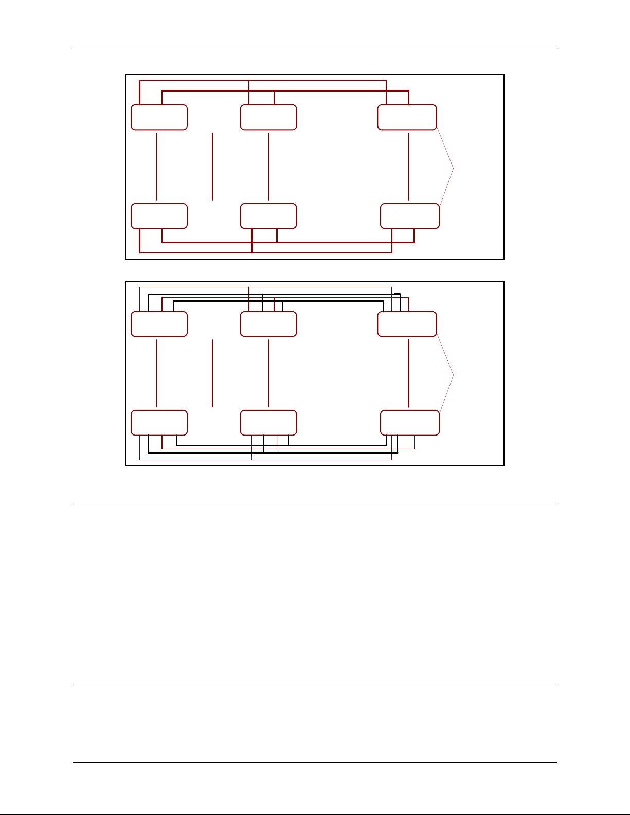
DEVICE
DEVICE
<==15 UNITS==>
<==15 UNITS==>
DEVICE
32 TRANSPONDER
DEVICE
RS485
TRANSPONDER
RS485
TRANSPONDER
Figure 4.7: 2-Wire RS485 Communication Installation Connection with Transponder
DEVICE
<==31 UNITS==>
DEVICE
32 TRANSPONDER
RS485
TRANSPONDER
COMPUTER
COMPUTER
DEVICE
<==31 UNITS==>
DEVICE
RS485
TRANSPONDER
Figure 4.8: 4-Wire RS485 Communication Installation Connection with Transponder
4.3: Network of Instruments and Long Distance Communication
Use the RS485 Transponder for a large instrument network. In a two-wire connection, a maximum of 900
instruments can be included in the same network (Figure 4.7). In a four-wire connection, a maximum of
3600 instruments can be included in the same link (Figure 4.8).
You may want to use a Modem Manager RS485-RS232 Converter. When speaking to most RS485 or
RS232C based devices, the remote modem must be programmed for the communication to work. This
task is often quite complicated because modems are quirky when talking to remote devices. To make this
task easier, EIG has designed a Modem Manager RS485 to RS232C converter. This device automatically
programs the modem to the proper configuration. Also, if you have poor telephone lines, modem manager
acts as a line buffer, making the communication more reliable. Use modems (dedicated or dial-up) when
the instruments are at great distances. However, set the modem to auto answer at the recommended
1200 baud rate if noise conditions exist.
4.4: Compatible Software (Optional)
Compatible software for the Futura+ Series is Communicator EXT. Use this software for data-download if
memory options are ordered. This software has multimeter connection capability for reading real-time
data.
Electro Industries/GaugeTech
23
 Loading...