

User's Manual
Table of Contents
Section Contents Page
1
2
3
Introduction
Installation &
Setup
Operation
1.1 The Projector ....................................................................................................1-1
1.2 Components......................................................................................................1-2
1.3 Purchase Record and Servicing.........................................................................1-2
2.1 Quick Setup ......................................................................................................2-1
2.2 Installation Considerations................................................................................2-2
2.3 Projector Position and Mounting......................................................................2-6
2.4 Source Connections ..........................................................................................2-9
2.5 Power Connection...........................................................................................2-12
2.6 Operating Orientation .....................................................................................2-13
2.7 Leveling..........................................................................................................2-13
2.8 Zoom, Focus & Vertical Offset.......................................................................2-14
2.9 Serial Port Connections ..................................................................................2-14
2.10 Keypad Protocols............................................................................................2-17
3.1 Overview...........................................................................................................3-1
3.2 Projector Basics................................................................................................3-1
3.3 Using the Keypads............................................................................................3-3
3.4 Navigating the Menus.......................................................................................3-9
3.5 Using Sources and Channels...........................................................................3-13
3.6 Adjusting the Image........................................................................................3-17
3.7 Adjusting and Checking System Parameters...................................................3-28
3.8 Using Multiple Projectors...............................................................................3-33
3.9 Error Conditions .............................................................................................3-34
4
5
6
54-007079-03P (10/98) Software Version 2.1
Maintenance
Specifications
Appendices
NOTE: Due to constant research, the information in this manual is subject to change without notice
4.1 Warnings and Guidelines..................................................................................4-1
4.2 Cleaning............................................................................................................4-3
4.3 Replacing Keypad Batteries..............................................................................4-3
4.4 Replacing the Lamp and Filter..........................................................................4-4
4.5 Replacing the Lens............................................................................................4-8
4.6 Troubleshooting................................................................................................4-8
5.1 Specifications....................................................................................................5-1
A Glossary...........................................................................................................A-1
B Keypad Reference ........................................................................................... B-1
C Menu Tree ........................................................................................................ C-1
D Serial Communication Cables..........................................................................D-1
E Throw Distance................................................................................................ E-1
F Optional Input Modules ....................................................................................F-1
VistaGRAPHX 2500
User's Manual
iii
Section 1
Introduction
1.1 The Projector
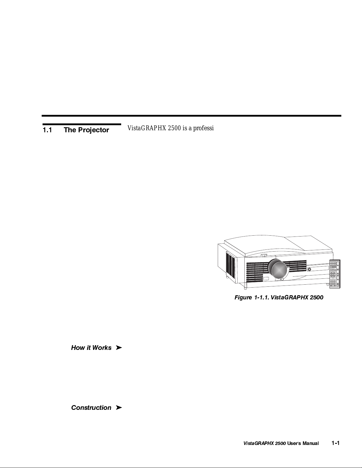
VistaGRAPHX 2500 is a professional-quality DMD projector that uses Digital
Light Processing
brightness multimedia and video projection. It is ideal for use in large audience
venues in which there may be high levels of ambient light, such as in
auditoriums and lecture halls. The VistaGRAPHX 2500 is compatible with
standard international video formats and can interface with IBM-compatible
PCs, Macintosh
1024 X 768 pixels resolution
◊
2500 ANSI lumens, contrast ratio of 250:1 ANSI, 400:1 full field
◊
interchangeable lenses for diagonal screen sizes up to 40 feet
◊
NTSC, PAL and SECAM compatible (requires optional decoder)
◊
displays input from PCs, VCRs, laser-disc players, video cameras, etc.
◊
intuitive on-screen menus
◊
for setup and control
built-in and infrared (IR)
◊
remote keypads
controller and switcher
◊
compatibility
keypad selectable input
◊
switching
RS-232 input with loop-
◊
through for networking
multiple projectors
RS-422 input for long distance control
◊
5-language capability
◊
modular design for ease of servicing
◊
(DLP) technology from Texas Instruments to achieve high-
computers, and workstations. Features include:
Figure 1-1.1. VistaGRAPHX 2500
How it Works
Construction
VistaGRAPHX 2500 accepts data/graphics and video input signals for projection onto
'
flat or curved front or rear projection screens. High brightness light is generated by an
internal 500 watt CERMAX
(digital micromirror dev ice) panels which each provide digitiz ed red, green, or blue
color information. Light from the "ON" pixels of each panel is reflected, conv erged and
then projected to the screen through a single front lens, where the pixels are all
superimposed to create a sharp full-color imag e.
The projector body is comprised of powder-coated aluminum and an ABS front
'
bezel. Covers can be removed as necessary for quick replacement of the lamp or
filter. The projector's modular internal design provides for ease-of-service and
minimal down-time.
Xenon lamp. This light is modulated by three DMD
VistaGRAPHX 2500
User's Manual
1-1
INTRODUCTION
1.2 Components
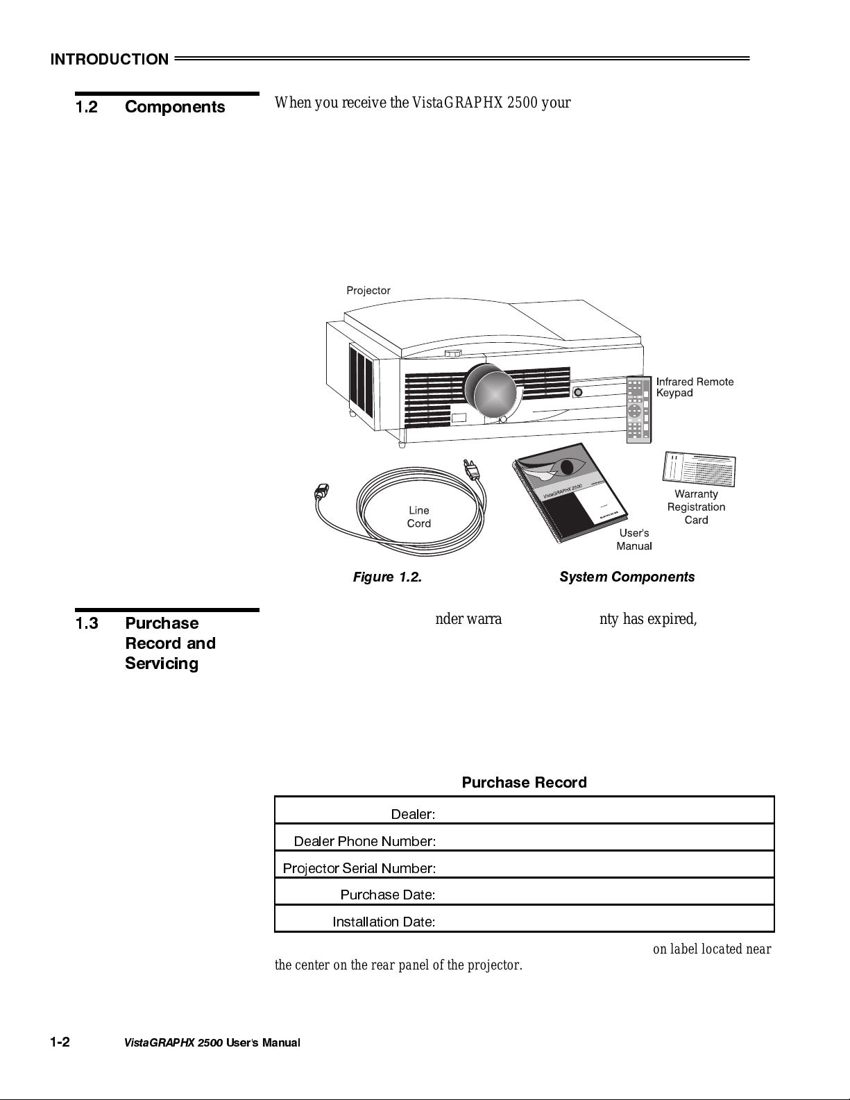
When you receive the VistaGRAPHX 2500 your dealer will have already
unpacked it, inspected it, and prepared it for use. Included with the standard
projector is an IR Remote Keypad, a VistaGRAPHX 2500 Line Cord (power
cord), a VistaGRAPHX 2500 User's Manual and a Warranty Registration Card.
Make sure you have all these items. Immediately fill out the warranty
registration card and mail it directly to Electrohome.
NOTE: VistaGRAPHX 2500 does not include a video decoder module
(optional). This manual assumes that the video decoder option has been installed
in the projector.
1.3 Purchase
Record and
Servicing
Figure 1.2.
VistaGRAPHX 2500
System Components
Whether the projector is under warranty or the warranty has expired,
Electrohome’s extensive factory and dealer service network is always available.
Electrohome service technicians are fully trained to quickly diagnose and correct
projector malfunctions. Complete service manuals and updates are available to
service technicians for all new projector models manufactured by Electrohome.
If you have a problem with your projector and require assistance, contact the authorized
Electrohome dealer from which the projector was purchased. In m any cases, servicing
can be performed on site. Fill out the information below for your records.
Purchase Record
Dealer:
Dealer Phone Number:
Projector Serial Number:
Purchase Date:
Installation Date:
NOTE: The projector serial number is on the projector's identification label located near
the center on the rear panel of the projector.
1-2
VistaGRAPHX 2500
User's Manual
Section 2
Installation & Setup
This section explains how to install and set up the projector. If you are familiar with the projector and want to
quickly set it up for temporary use, follow the Quick Setup instructions. For a complete setup, follow the
instructions and guides covered in the remaining subsections.
NOTES: 1) The lens for the projector is not mounted when shipped from the factory. For instructions on how to
install or replace a lens, refer to 4.5, Replacing the Lens. 2) This manual assumes the video decoder is installed.
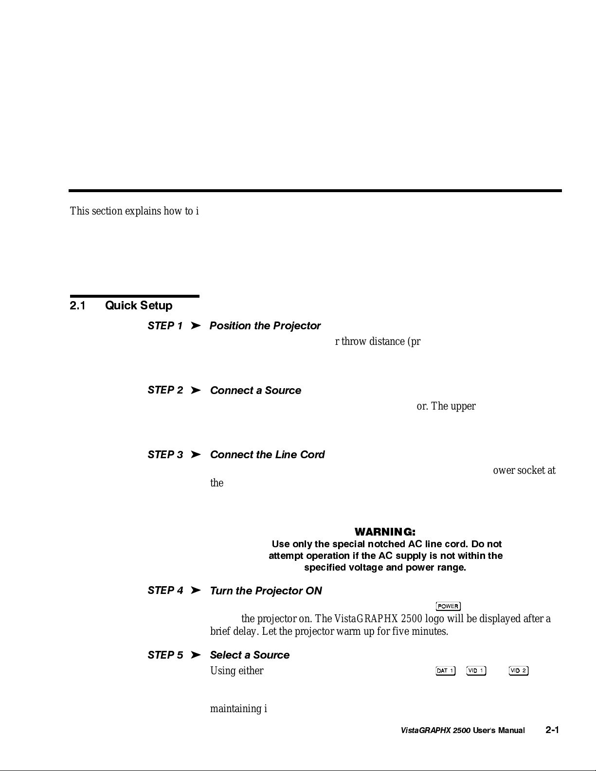
2.1 Quick Setup
STEP 1
STEP 2
STEP 3
Follow these 6 steps for quick setup of the projector.
'
Position the Projector
Set the projector at the proper throw distance (projector-to-screen distance) and
vertical position. See 2.3, Projector Position and Mounting. Make sure that the
projector is level from side-to-side (see 2.7, Leveling).
'
Connect a Source
Locate the input panels at the rear of the projector. The upper right panel accepts
an RGB input (via BNC connectors). The lower left panel accepts a composite
video and S-video input. Connect a source to the appropriate panel.
'
Connect the Line Cord
Plug the special notched AC line cord (power cord) into the AC power socket at
the left rear of the projector. This cord is rated at 15 amps rather than the 8-10
amps in other typical cords. Input power required is 100 VAC to 240 VAC, 50 to
60 Hz @ 11 amps.
WARNING:
Use only the special notched AC line cord. Do not
attempt operation if the AC supply is not within the
specified voltage and power range.
STEP 4
STEP 5
'
Turn the Projector ON
Using either the built-in or IR remote keypad, press
to turn the projector on. The VistaGRAPHX 2500 logo will be displayed after a
brief delay. Let the projector warm up for five minutes.
'
Select a Source
Using either the built-in or IR remote keypad, press , , or to
select and display the image for the source you have connected in Step 2. By
default, it will resize as needed — the image will be as large as possible while
maintaining its original aspect ratio.
VistaGRAPHX 2500
and hold for a second
User's Manual
2-1
INSTALLATION & SETUP
STEP 6
2.2 Installation
Considerations
Installation Type
'
Make Necessary Display Adjustments
With the input image displayed, rotate the lens barrel to increase or decrease
image size (applies to zoom lenses only). Next, rotate the focus adjustment knob
(next to the lens barrel) to achieve best focus. Then rotate the nearby Vertical
Offset knob to achieve the best overall image position, focus and brightness
without distorting the geometry of the image. Press
adjustments, press
if you want to select a different source/channel. See 3.5,
to refine other display
Using Sources and Channels.
Although VistaGRAPHX 2500 delivers a high brightness quality output, the final
display quality could be compromised if the projector is not properly installed.
This subsection discusses issues you should consider before proceeding with a
final installation. Even if you do not intend to use VistaGRAPHX 2500 in a fixed
and permanent installation, this subsection will help you to better understand
what may be done to enhance display performance.
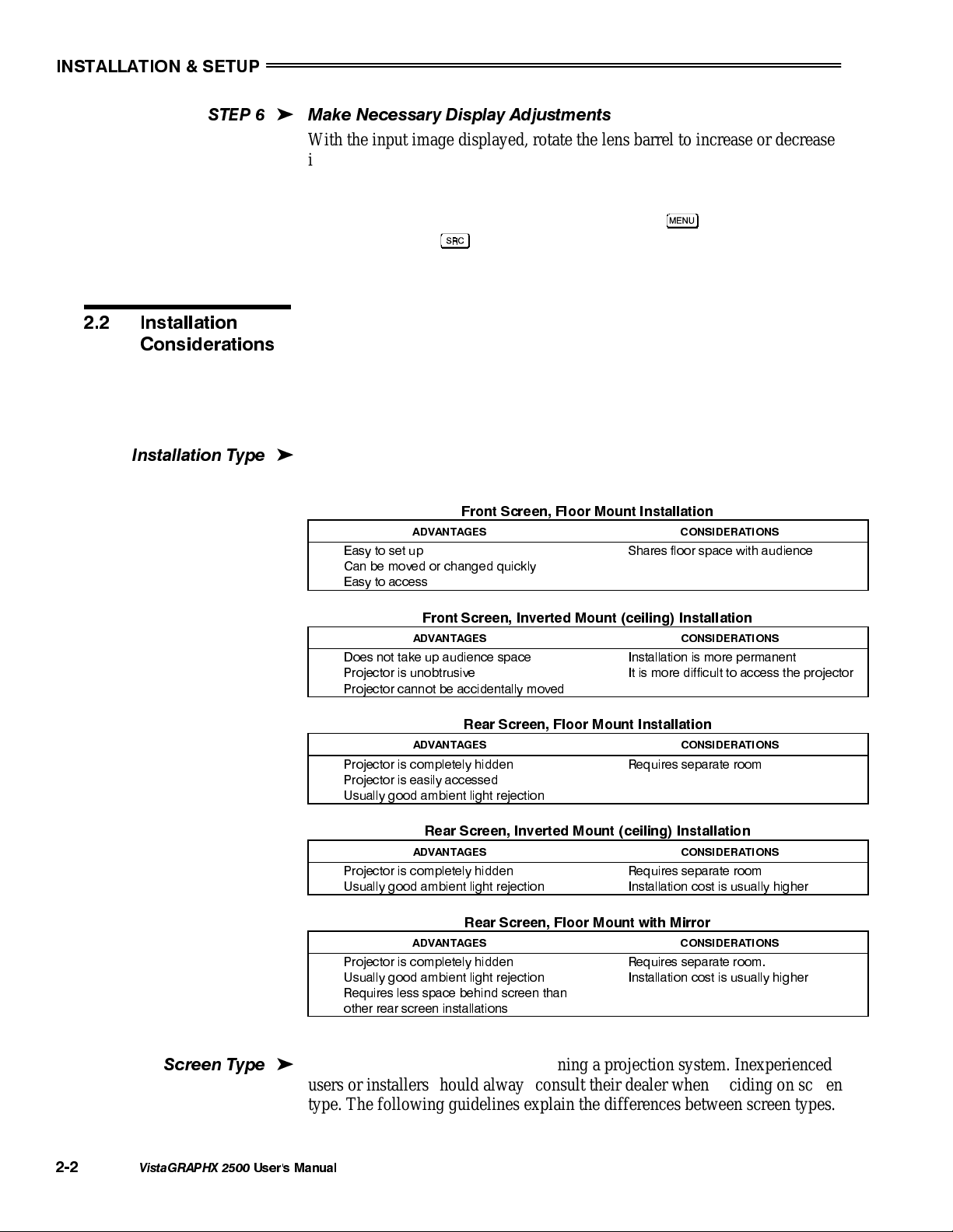
Choose the installation type which suits your needs: front or rear screen, floor
'
mount or inverted mount.
Front Screen, Floor Mount Installation
ADVANTAGES CONSIDERATIONS
•
Easy to set up
•
Can be moved or changed quickly
•
Easy to access
•
Shares floor space with audience
Screen Type
Front Screen, Inverted Mount (ceiling) Installation
ADVANTAGES CONSIDERATIONS
•
Does not take up audience space
•
Projector is unobtrusive
•
Projector cannot be accidentally moved
Rear Screen, Floor Mount Installation
ADVANTAGES CONSIDERATIONS
•
Projector is completely hidden
•
Projector is easily accessed
•
Usually good ambient light rejection
Rear Screen, Inverted Mount (ceiling) Installation
ADVANTAGES CONSIDERATIONS
•
Projector is completely hidden
•
Usually good ambient light rejection
Rear Screen, Floor Mount with Mirror
ADVANTAGES CONSIDERATIONS
•
Projector is completely hidden
•
Usually good ambient light rejection
•
Requires less space behind screen than
other rear screen installations
Screen type is important when designing a projection system. Inexperienced
'
•
Installation is more permanent
•
It is more difficult to access the projector
•
Requires separate room
•
Requires separate room
•
Installation cost is usually higher
•
Requires separate room.
•
Installation cost is usually higher
users or installers should always consult their dealer when deciding on screen
type. The following guidelines explain the differences between screen types.
2-2
VistaGRAPHX 2500
User's Manual
INSTALLATION & SETUP
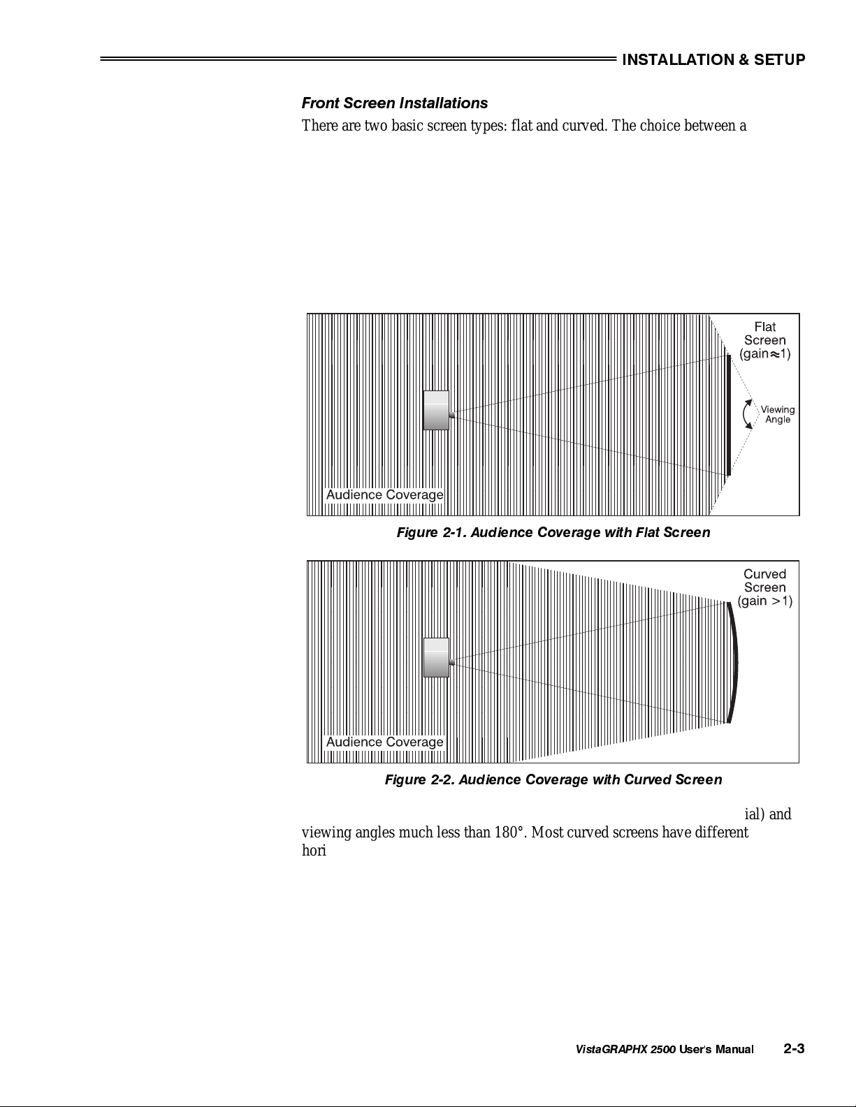
Front Screen Installations
There are two basic screen types: flat and curved. The choice between a flat
screen or a curved screen is dependent on audience viewing angle and screen
gain. There is always a trade-off between viewing angle and gain. Viewing
angles for both screen types are illustrated in Figure 2-1 and Figure 2-2 (plan
views).
Flat screens offer a gain of about 1 with a viewing angle just less than 180°.
Incident light reflects equally in all directions so the audience can see the display
from various angles. Because of the lower gain, flat screens are more effective
when ambient lighting is reduced.
Figure 2-1. Audience Coverage with Flat Screen
Figure 2-2. Audience Coverage with Curved Screen
Curved screens have gains larger than 1 (due in part to the screen material) and
viewing angles much less than 180°. Most curved screens have different
horizontal and vertical viewing angles. Incident light does not reflect equally in
all directions. The reflected light concentrates in a conical volume or "viewing
cone". Audiences within the viewing cone see a brighter image than that from an
equal area on a flat screen. Audiences outside the viewing cone see a dimmer
image.
NOTE: VistaGRAPHX 2500 lenses are designed primarily for use with flat
screens. However, its depth-of-field range allows the lens to be focused on
curved screens as well. Focus remains sharp in the corners, however there may
be significant pincushion distortion, primarily at the top of the screen.
VistaGRAPHX 2500
User's Manual
2-3
INSTALLATION & SETUP
g
Screen Size
Rear Screen Installations
There are two basic types of rear screens: diffused and optical. A diffused screen
has a surface which spreads the light striking it. Purely diffused screens have a
gain of less than 1. The main advantage of the diffused screen is its wide viewing
angle, similar to that of a flat screen for front screen projection. Optical screens
take light from the projector and redirect it to increase the light intensity at the
front of the screen. This reduces it in other areas. A viewing cone, similar to that
of a curved front screen installation, is created.
To summarize, optical screens are better suited for brightly lit rooms where the
audience is situated within the viewing cone. Diffused screens are best suited
when a wide viewing angle is required but there is low ambient room lighting.
Screen size may be from 6 to 40 feet diagonal, depending on the lens you are
'
using. For instance, a 1:1 lens produces a 6-30 foot image size, whereas a 4-7:1
zoom lens produces a 10-40 foot image size. Choose a screen size which is
appropriate for your lens and application. Keep in mind that if the projector will
be used to display text information, the image size must allow the audience to
recognize all text clearly. The eye usually sees a letter clearly if eye-to-text
distance is less than 150 times the height of the letter. Small text located too far
from the eye may be illegible at a distance despite the image being projected
sharply and clearly on the screen.
Room Lightin
To fill a screen with an image, the aspect ratio of the screen should be equal to
the aspect ratio of the image. The aspect ratio of an image is expressed as the
ratio of its width to its height. Standard video from a VCR has a 4:3 or 1.33:1
aspect ratio. For example, to display a VCR output with a 4:3 aspect ratio onto a
10 foot (3m) high screen, the width of the screen must be at least 13.3 feet (4m).
Note: Screen size is often specified as diagonal size. Screens specified by
diagonal size have aspect ratios of 4:3. Screens with other aspect ratios are not
typically specified by diagonal size.
The high brightness output of VistaGRAPHX 2500 is well suited for locations
'
where ambient lighting is less than optimum for projection; however, it is
desirable that the projector be operated in an ideal projection room environment.
For temporary installations where the room may not be designed for projection,
there are many simple things which can be done to avoid problems caused by
unwanted light.
Visiting a movie theater can give you an idea of what makes a good projection
environment. Walls, floors and furnishings are dark and matte finished. A
projection room should not have white reflective ceilings or non-directional
lighting such as fluorescent lights. The white ceiling spreads light, making the
room appear brighter. Keep lighting and reflections to a minimum.
2-4
VistaGRAPHX 2500
If it is not possible to eliminate fluorescent lights, consider using parabolic
reflectors ("egg crates") to direct light down to the floor. Incandescent spot
lighting is a better way to obtain illumination. Light dimmers or rheostats allow
you to further control the lighting.
User's Manual
INSTALLATION & SETUP
Outside windows are undesirable in any projection room. A small crack between
curtains on a sunny day can wash out a projected image. If you do have
windows, make sure that window coverings are opaque and overlapping — some
window coverings are designed to provide up to 100 percent blockage of outside
light. Ideally, the material should have a matte finish.
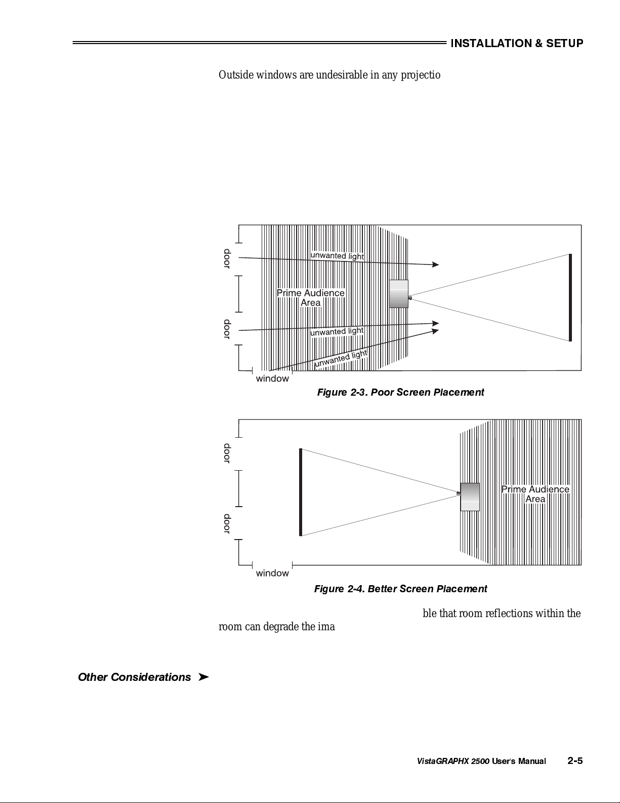
To minimize the effects caused by unwanted light from door and aisle ways,
carefully choose the position of your projector and screen. Figure 2-3 shows an
installation where poor screen placement allows too much unwanted light to
enter the screen. In Figure 2-4, the screen and the projector are positioned so that
unwanted light is minimized.
Other Considerations
Figure 2-3. Poor Screen Placement
Figure 2-4. Better Screen Placement
Even with all lighting removed it is still possible that room reflections within the
room can degrade the image. Light from the projection screen should be
absorbed by the ceilings, walls and floors so that it will not be reflected back to
the screen. Again, reflective surfaces should be kept to a minimum.
Here are some other considerations and tips which can help you improve your
'
installation:
• Ventilation is an important factor when preparing a projection room. The
ambient temperature should be kept constant and below 35°C (95°F). Keep
VistaGRAPHX 2500
User's Manual
2-5
INSTALLATION & SETUP
the projector away from heating and/or air conditioning vents. Changes in
temperature can cause drifts in the projector circuitry which may affect
performance.
• Keep the projector away from devices which radiate electromagnetic energy
such as motors and transformers. Common sources of these are slide
projectors, speakers, power amplifiers, elevators, etc.
• For rear screen applications, less space is required if a mirror is used to fold
the optical path.
• Choose the right screen size for the application:
◊ As screen size increases, magnification increases which reduces
brightness. Select a screen size which is appropriate for the venue,
but not larger than that required.
◊ Installing a large screen in a small room is similar to watching
television close up; too large a screen can overpower a room. A good
rule of thumb is to be no closer than 1.5 times the width of the
screen.
◊ Larger screens require greater attention to lighting conditions.
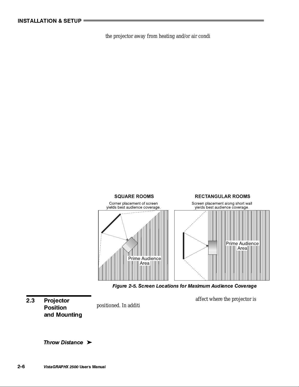
• When laying out the projection room, consider positioning the projector and
screen in a manner which will achieve maximum audience coverage and
space efficiency. For example, placing the screen along the larger wall in a
rectangular room will reduce audience coverage. Figure 2-5 shows two
examples of how audience coverage is maximized.
2.3 Projector
Position
and Mounting
Throw Distance
2-6
VistaGRAPHX 2500
Installation type, screen type, and lighting all affect where the projector is
positioned. In addition, both throw distance (the distance between the projector
and screen) and vertical position (the height of the projector in relation to the
screen) must be determined for every new installation. Both depend on the
screen size and projector lens type you are using. Make sure that the room can
accommodate the required position of the projector for the chosen screen size.
Throw distance is the distance between the projector's front feet and the screen.
'
It is measured perpendicular to the lens surface and screen surface. As you move
the projector farther from the screen, the image becomes larger.
User's Manual
Figure 2-5. Screen Locations for Maximum Audience Coverage
INSTALLATION & SETUP
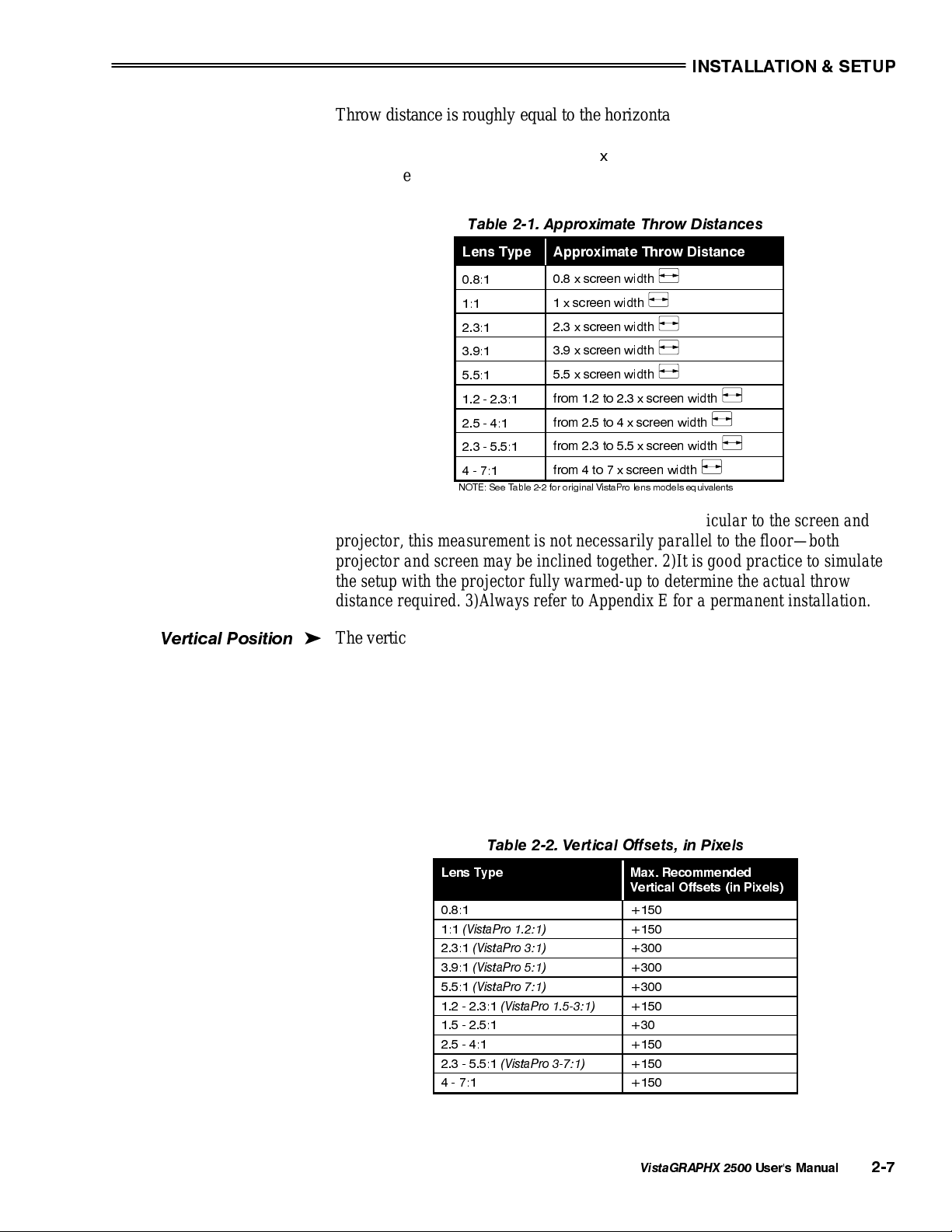
Throw distance is roughly equal to the horizontal width of the screen multiplied
by the type of lens you are using (for example, if using a 3.9:1 lens, throw
distance should be approximately 3.9
the screen width). Once you know your
x
screen size, you can closely estimate how far away the projector should be, as
shown in Table 2-1, or refer to Appendix E for a permanent installation.
Table 2-1. Approximate Throw Distances
Lens Type Approximate Throw Distance
Vertical Position
0.8:1
1:1
2.3:1
3.9:1
5.5:1
1.2 - 2.3:1
2.5 - 4:1
2.3 - 5.5:1
4 - 7:1
NOTE: See Table 2-2 for original VistaPro lens models equivalents
0.8 x screen width
1 x screen width
2.3 x screen width
3.9 x screen width
5.5 x screen width
from 1.2 to 2.3 x screen width
from 2.5 to 4 x screen width
from 2.3 to 5.5 x screen width
from 4 to 7 x screen width
NOTES: 1)While throw distance is measured perpendicular to the screen and
projector, this measurement is not necessarily parallel to the floor—both
projector and screen may be inclined together. 2)It is good practice to simulate
the setup with the projector fully warmed-up to determine the actual throw
distance required. 3)Always refer to Appendix E for a permanent installation.
The vertical position of the projector in relation to the screen also depends on the
'
size of the screen and the lens type. Correct vertical position helps ensure that
the image will be rectangular in shape rather than keystoned (having non-parallel
sides) and that image quality remains at its best.
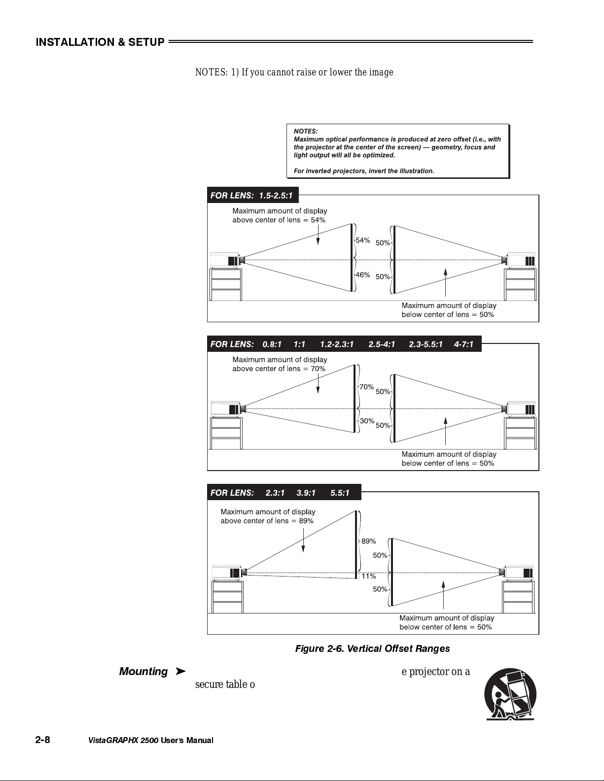
Vertical position can be manually offset—that is, the image can be moved up—
using the vertical adjustment knob on the front of the projector. The range of
offset adjustment depends on the lens type you are using (Table 2-2 . In addition,
refer to Figure 2-6 to see more clearly how the pixel offset ranges affect the
placement of your image in relation to the projector.
Table 2-2. Vertical Offsets, in Pixels
Lens Type Max. Recommended
0.8:1 +150
1:1
(VistaPro 1.2:1)
2.3:1
(VistaPro 3:1)
3.9:1
(VistaPro 5:1)
5.5:1
(VistaPro 7:1)
1.2 - 2.3:1
1.5 - 2.5:1 +30
2.5 - 4:1 +150
2.3 - 5.5:1
4 - 7:1 +150
(VistaPro 1.5-3:1)
(VistaPro 3-7:1)
Vertical Offsets (in Pixels)
+150
+300
+300
+300
+150
+150
VistaGRAPHX 2500
User's Manual
2-7
INSTALLATION & SETUP
g
NOTES: 1) If you cannot raise or lower the image enough for your installation, or if the
image becomes keystoned or exhibits uneven brightness, the projector is probably too
high or low in relation to the screen. 2) Recommended offset ranges can be exceeded,
however this may affect focus.
2-8
Mountin
VistaGRAPHX 2500
For typical front or rear floor mounts, mount the projector on a
'
secure table or cart. Take care with a mobile cart—avoid
sudden stops, excessive force and uneven surfaces that may cause
th e p r o j e c t o r a n d c a r t c o m b i n a t i o n t o overturn.
User's Manual
Figure 2-6. Vertical Offset Ranges
INSTALLATION & SETUP
p
The table or cart should be reasonably level. Fine adjustments to the projector
level can be made by adjusting the height of the projector legs; refer to 2.7,
Leveling for details.
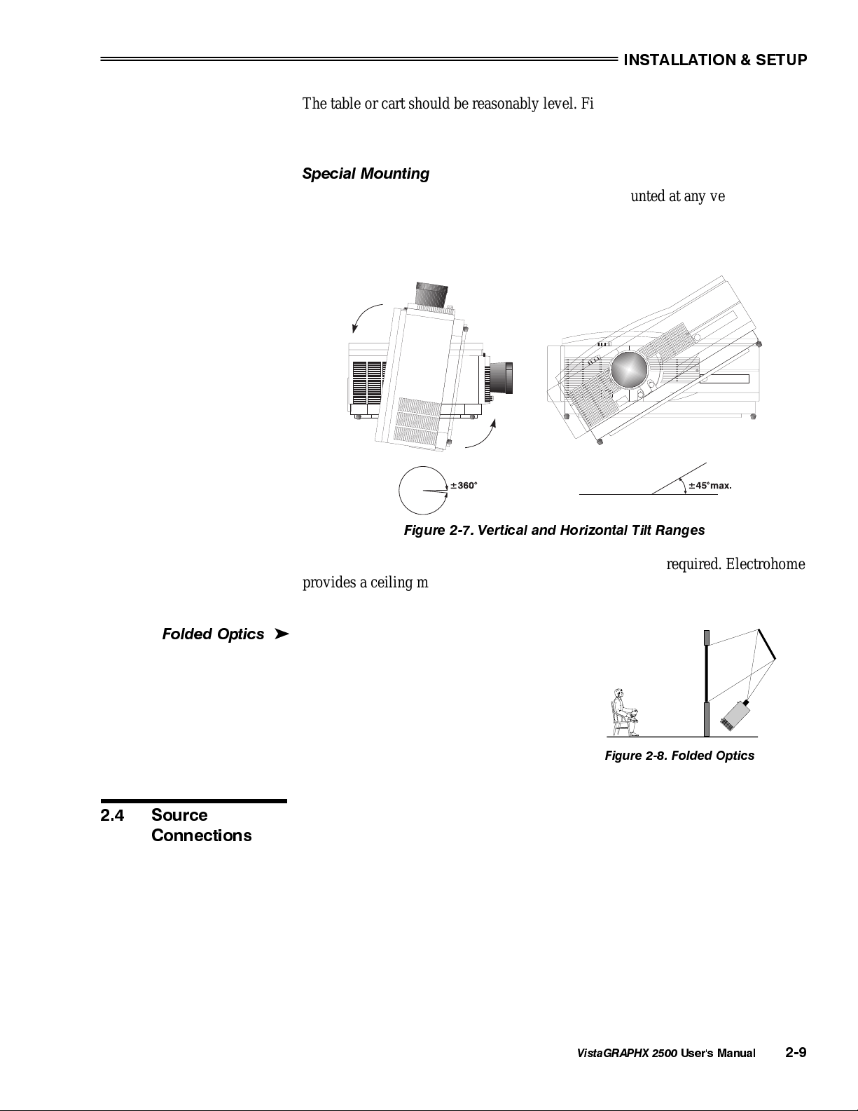
Special Mounting
Note that VistaGRAPHX 2500 can be rotated and mounted at any vertical anglei.e., you can tilt the projector forwards or backwards as much as desired for your
application. The side-to-side tilt, however must not exceed 45° (see Figure 2-7).
This limit ensures that the arc lamp in the projector operates properly and safely.
Folded O
2.4 Source
Connections
tics
Figure 2-7. Vertical and Horizontal Tilt Ranges
If the projector is to be inverted, a ceiling mount fixture is required. Electrohome
provides a ceiling mount kit for assembly and installation by a dealer/installer.
For more information, contact your dealer or Electrohome.
In rear screen applications where space behind
'
the projector is limited, a mirror may be used
to fold the optical path. See
Figure 2-8. The
position of the projector and mirror must be
accurately set. If considering this type of
installation, call your dealer for assistance.
Figure 2-8. Folded Optics
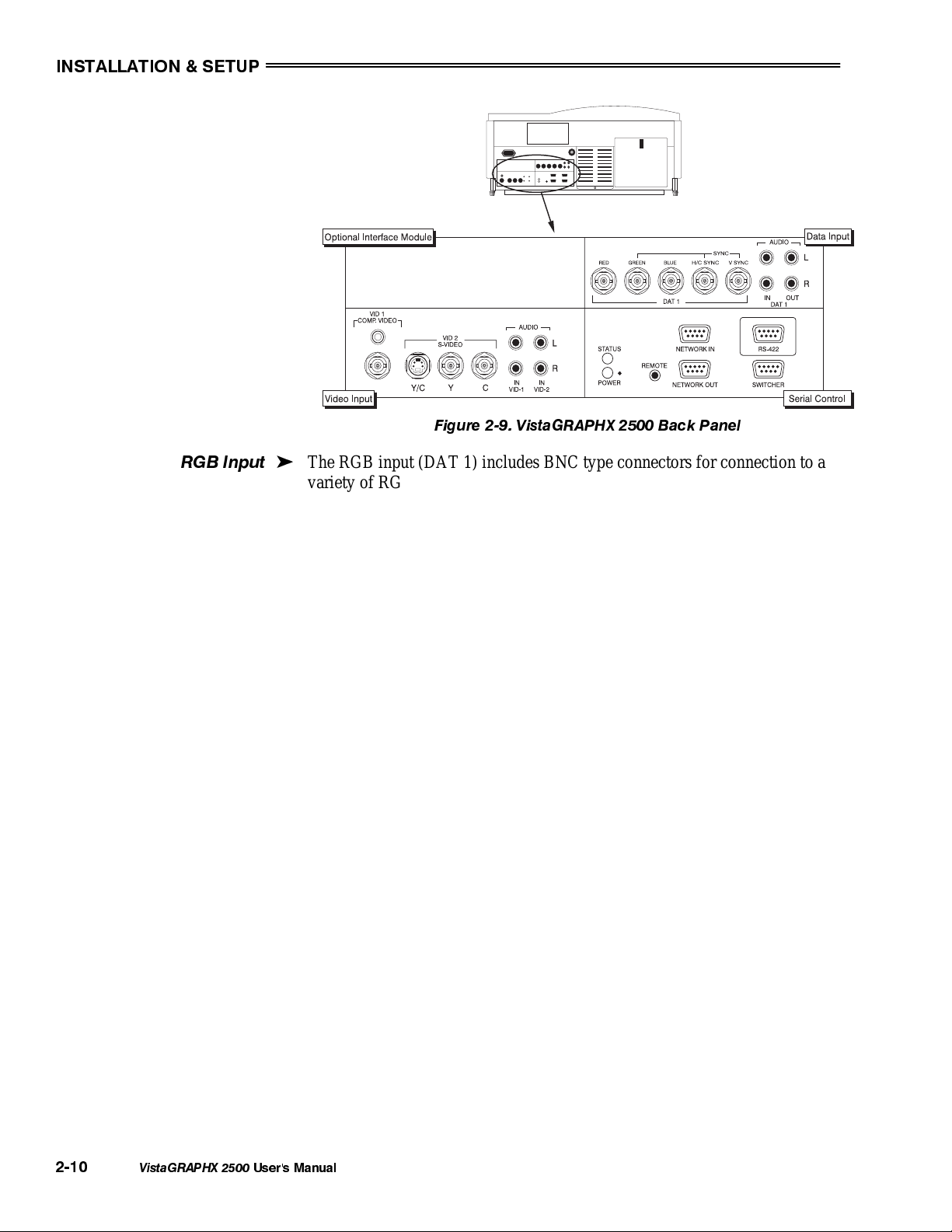
The rear panel of the projector has two standard input panels to which you may
connect a variety of sources. The upper right panel (DAT 1) accepts an RGB
input from an external RGB source with audio follow-through. The lower left
panel (if video decoder module is installed) accepts composite video (VID 1) or
S-video (VID 2) and audio from devices such as video tape or disk players.
There are also several optional interfaces available for connecting other sources
(DAT 2). Such an option installs in the upper left panel. See Figure 2-9.
VistaGRAPHX 2500
User's Manual
2-9
INSTALLATION & SETUP
p
Figure 2-9. VistaGRAPHX 2500 Back Panel
RGB In
ut
The RGB input (DAT 1) includes BNC type connectors for connection to a
'
variety of RGB sources. Such sources include VGA, SVGA, XGA, Mac,
PowerMac, DEC, Sun, SGI and others. VistaGRAPHX 2500 supports multiple
sync types: sync-on-green for data, composite, and separate H & V.
NOTES: 1)Depending on the source, you may need a custom adapter cable that
has BNC connectors at the projector end and different type of connector at the
other (such as a 15-pin "D" connector for computer sources). Contact your
dealer or Electrohome. 2)For best performance of HDTV sources, do not
connect to Dat1 — use the HDTV Input Module (option).
Connect the sync BNC input(s) first. Then connect the red, green and blue
source outputs to the RED, GREEN, and BLUE inputs on the panel. If the source
uses sync-on-green, only the red, green, and blue connections are required. If the
source provides a composite sync output, connect it to the H/C SYNC input. If
the source provides separate horizontal and vertical sync outputs, connect
horizontal sync to the H/C SYNC input and connect vertical sync to the V SYNC
input. See Figure 2-10.
Connect YUV (component) video as follows:
Y to "Green"
U (also called B-minus-Y) to "Blue"
V (also called R-minus-Y) to "Red"
2-10
VistaGRAPHX 2500
NOTE: VistaGRAPHX 2500 does not automatically recognize a YUV signal.
When using YUV video, you must specify this signal type within the Image
Settings menu so that the projector can distinguish between this signal and other
RGB sources. See 3.6, Adjusting the Image.
User's Manual
INSTALLATION & SETUP
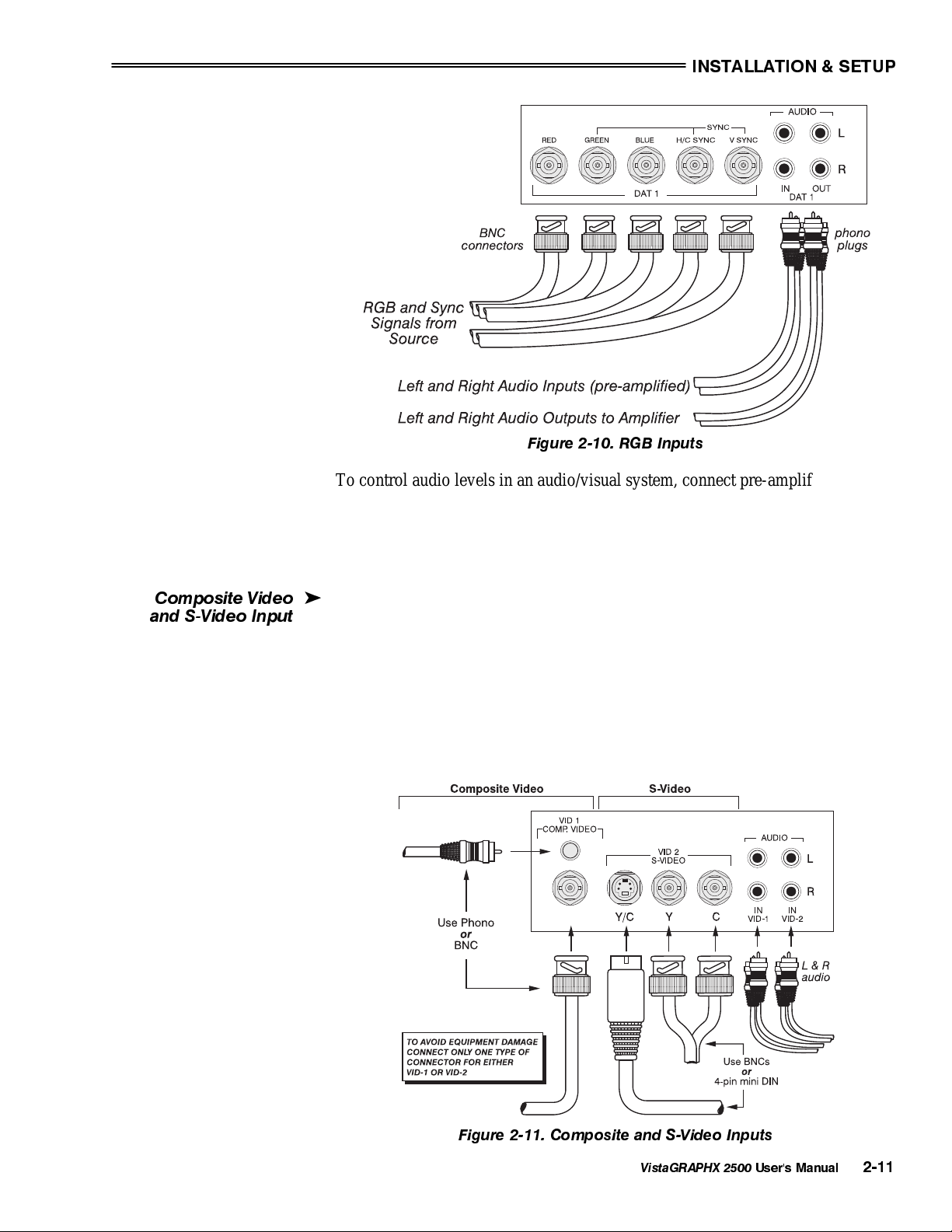
Figure 2-10. RGB Inputs
To control audio levels in an audio/visual system, connect pre-amplified (line
level) audio inputs to the left and right channel audio inputs on the DAT 1 panel.
Then connect the audio outputs to external audio amplification equipment for
sound output. All audio connection cables require standard RCA type phono
plugs.
Composite Video
and S-Video Input
The Composite/S-Video input provides simultaneous connection of both a
'
composite video source (VID 1) and an S-Video source (VID 2).
If connecting a S-Video source, use the 4-pin mini DIN connector or the Y and C
BNC connectors (luminance and chrominance) — do not use both as input. If
connecting a composite video source, use the Composite BNC connector or the
RCA phono jack — do not use both as input. See Figure 2-11.
NOTE: If using the loop-through feature for composite or S-Video input, see
"Video Termination" in 3.7, Adjusting and Checking System Parameters.
Figure 2-11. Composite and S-Video Inputs
VistaGRAPHX 2500
User's Manual
2-11
INSTALLATION & SETUP
p
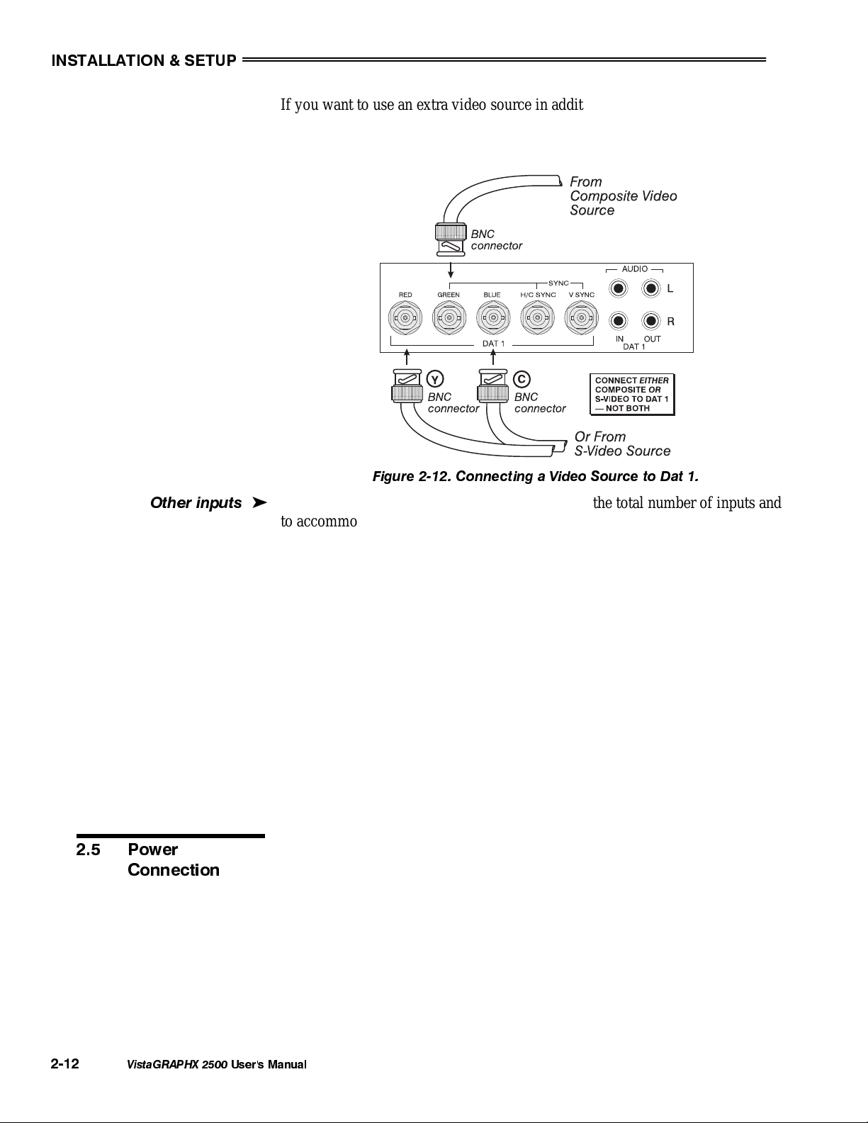
If you want to use an extra video source in addition to the video source(s)
connected at Vid 1 and/or Vid 2, connect either a Composite or S-Video source
to Dat 1 as shown in Figure 2-12.
Other in
2.5 Power
Connection
uts
Figure 2-12. Connecting a Video Source to Dat 1.
Optional interface modules allow you to increase the total number of inputs and
'
to accommodate other signal types. These modules may be installed in the upper
left section of the control panel on the rear of the VistaGRAPHX 2500 (Dat 2).
They are:
• RGB Input Module
• RGB Loop Thru Module
• Composite/S-Video Module
• HDTV Input Module
• PC Analog Input Module
NOTES: 1) Installation of optional interfaces must be done by qualified service
personnel only — contact your dealer or Electrohome. 2) See Appendix F,
Optional Input Modules for a brief description of each interface.
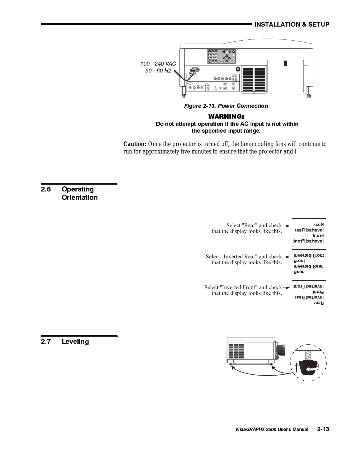
Plug the special notched AC line cord (power cord) into the line input socket
located at the left rear of the projector (Figure 2-13). Plug the three-prong end of
the line cord in a grounded AC outlet. Input voltage to the projector must be
between 100 and 240 VAC, 50 or 60 Hz. The power source must be capable of
supplying 1080 watts of power to the projector.
2-12
VistaGRAPHX 2500
User's Manual
INSTALLATION & SETUP
Figure 2-13. Power Connection
WARNING:
Do not attempt operation if the AC input is not within
the specified input range.
Caution: Once the projector is turned off, the lamp cooling fans will continue to
run for approximately five minutes to ensure that the projector and lamp have
sufficiently cooled, at which point the fans will automatically shut off. To avoid
damaging the projector, never unplug the line cord while the lamp cooling fans
are running. Do not unplug the projector in order to power down.
2.6 Operating
Orientation
2.7 Leveling
VistaGRAPHX 2500 is set up at the factory for use in a front screen, floor mount
orientation. If the installation is ceiling mount or rear screen, you may notice that
displayed images are upside down and/or reversed. To correct, you must change
the image orientation from within the Preferences menu (you may prefer to do
this before physically
installing the projector). See
Section 3, Operation for
further information.
In the Preferences menu,
highlight and select the
"Image Orientation" pulldown list. From a front
screen floor mount
installation, select from
Rear, Inverted Rear, Front
or Inverted Front according
to your intended installation:
For most installations, the lens surface
of the VistaGRAPHX 2500 projector
must be parallel to the screen to
prevent keystoning. To make small
corrections to the projector's level,
rotate each leg as necessary to raise or
lower.
VistaGRAPHX 2500
User's Manual
2-13
INSTALLATION & SETUP
2.8 Zoom, Focus &
Vertical Offset
Zoom
Focus
Vertical Offset
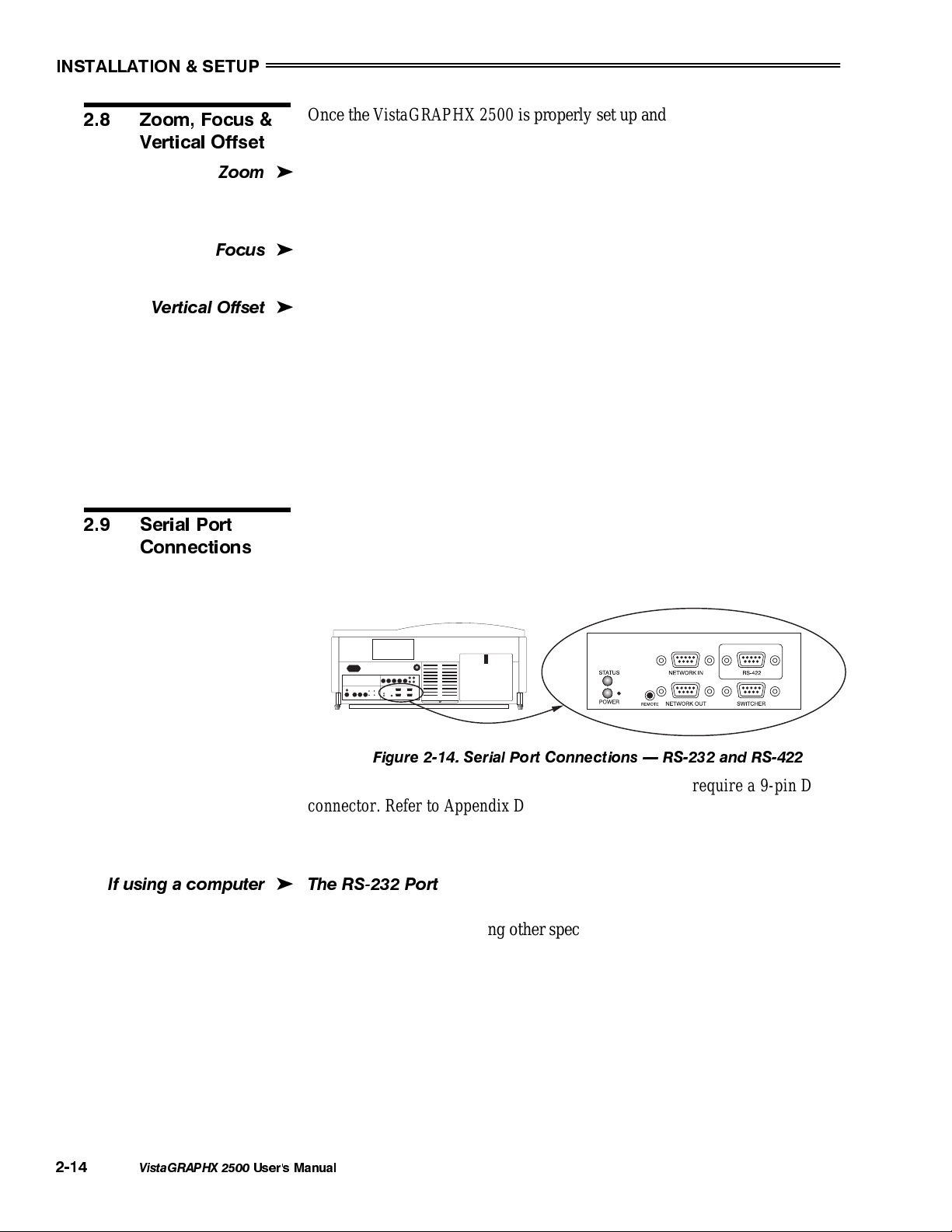
2.9 Serial Port
Connections
Once the VistaGRAPHX 2500 is properly set up and projecting an image on
screen, you are ready to make quick manual display adjustments.
If you are using a zoom lens, turn the outer shell of the lens barrel to decrease or
'
increase the size of the image at the current throw distance. Note: Do not touch
the lens surface as it can be easily damaged.
Turn the Focus adjustment knob (next to lens barrel) until you obtain the best
'
overall image clarity.
VistaGRAPHX 2500 includes a Vertical Offset adjustment knob to provide
'
vertical image shifting (raising and lowering) without causing keystone
distortion. Proper adjustment can also maximize display brightness. Turn the
knob until you achieve the best overall brightness without causing a distortion in
picture geometry.
For further display adjustments through keypad commands and on-screen menus,
refer to Section 3, Operation.
Use serial communication ports when controlling VistaGRAPHX 2500 with a
personal computer having a serial interface or when using the projector with a
Marquee switcher. VistaGRAPHX 2500 serial ports are located on the lower
right portion of the projector's rear control panel as shown in Figure 2-14.
2-14
If usinga computer
VistaGRAPHX 2500
NOTES: 1) All VistaGRAPHX 2500 serial connections require a 9-pin D
connector. Refer to Appendix D for complete cable wiring requirements. 2) The
"NETWORK OUT" port is provided for networking applications only — see "If
using multiple projectors", below.
'
The RS-232 Port
You may wish to use a computer rather than a keypad for controlling the
projector and for performing other special functions. From most computers,
connect an RS-232 serial communication cable between the computer and the
projector serial port labeled "NETWORK IN" (Figure 2-15). Then set the
projector baud rate to match that of the computer. Changing the baud rate is
described in 3.7, Adjusting and Checking System Parameters.
NOTE: In rare instances, some computers can provide RS-422 serial
communications (generally through a plug-in adapter or external converter). See
The RS-422 Port, below.
User's Manual
Figure 2-14. Serial Port Connections RS-232 and RS-422
INSTALLATION & SETUP
g
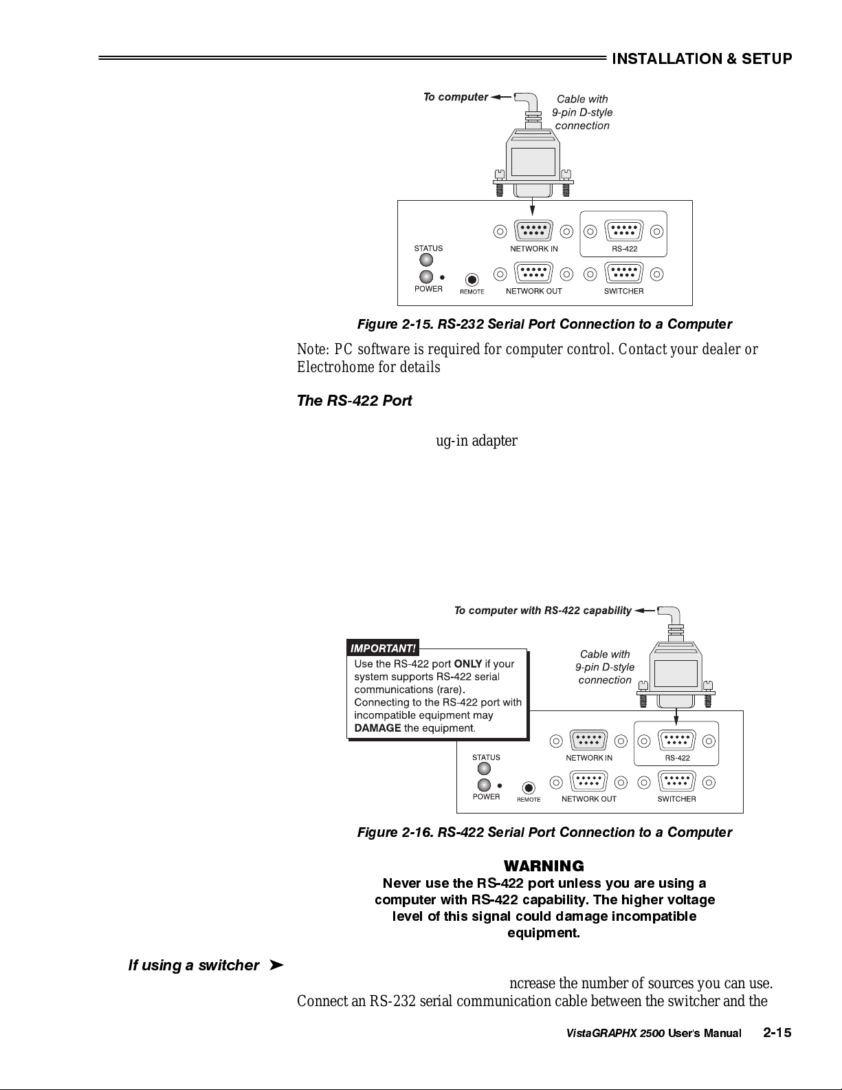
Figure 2-15. RS-232 Serial Port Connection to a Computer
Note: PC software is required for computer control. Contact your dealer or
Electrohome for details.
The RS-422 Port
In rare instances, some computers can provide RS-422 serial communications
(generally through a plug-in adapter or external converter) rather than the typical
RS-232 found on most computers. RS-422 communications occur at a higher
voltage level than RS-232 and are especially useful for distances greater than
600 feet. The projector’s RS-422 port is permanently set at 9600 baud.
If you wish to control the projector with a computer having RS-422 capability,
connect the computer to the projector’s RS-422 port instead of the port labeled
“NETWORK IN”. Again, use RS-422 only if you are certain that your computer
has RS-422 capability (consult your documentation). See Figure 2-16.
Figure 2-16. RS-422 Serial Port Connection to a Computer
WARNING
Never use the RS-422 port unless you are using a
computer with RS-422 capability. The higher voltage
level of this signal could damage incompatible
equipment.
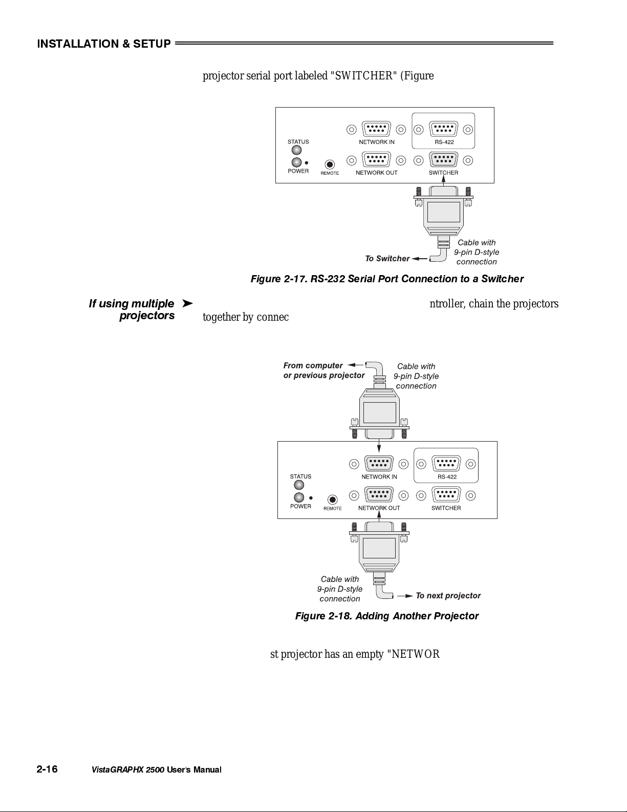
If usin
a switcher
You may wish to use one or more external Marquee switchers or third-party
'
switchers in order to significantly increase the number of sources you can use.
Connect an RS-232 serial communication cable between the switcher and the
VistaGRAPHX 2500
User's Manual
2-15
INSTALLATION & SETUP
proj
If using multiple
ectors
projector serial port labeled "SWITCHER" (Figure 2-17). This port is
permanently set at 9600 baud.
Figure 2-17. RS-232 Serial Port Connection to a Switcher
To control multiple projectors with a computer/controller, chain the projectors
'
together by connecting the "NETWORK OUT" connector of the first projector
(already connected to the computer/controller) to the "NETWORK IN"
connector of the next projector in the chain (Figure 2-18).
2-16
VistaGRAPHX 2500
Figure 2-18. Adding Another Projector
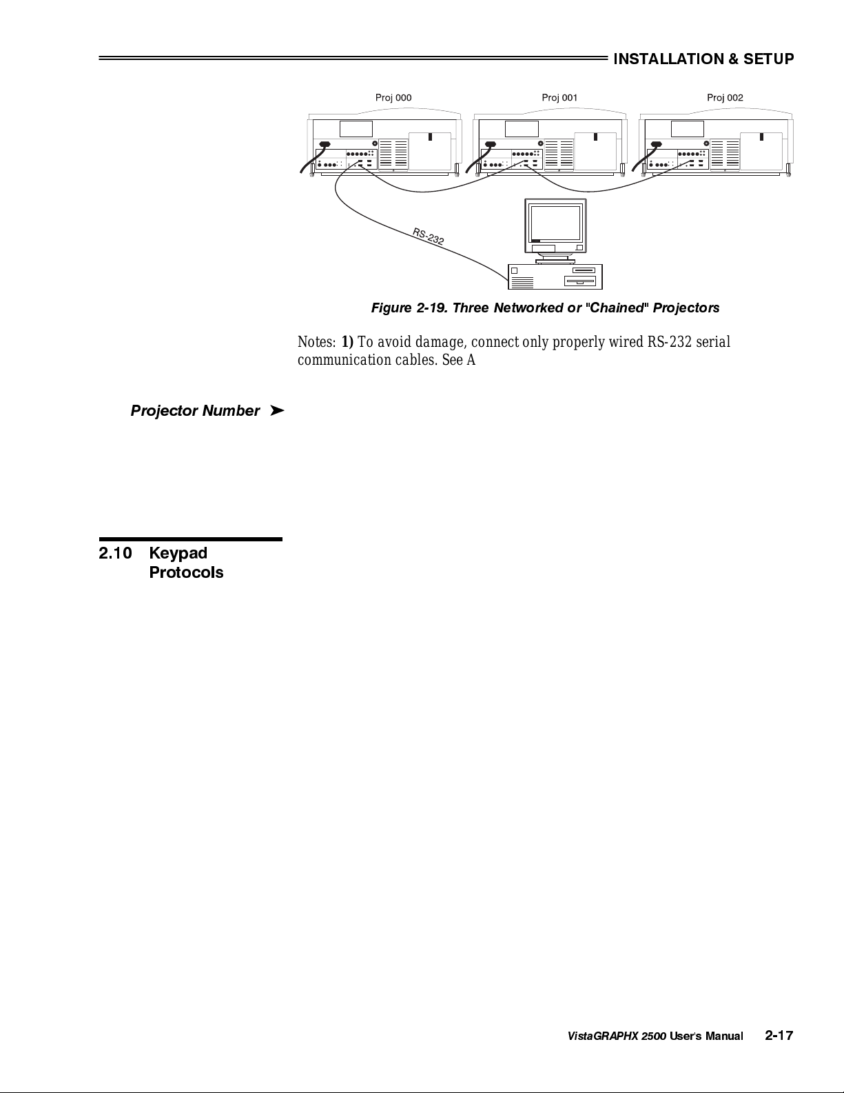
Continue connecting projectors in this way to the last projector in the chain, so
that only the last projector has an empty "NETWORK OUT" connector. See
Figure 2-19.
Communication parameters such as baud rate must be set to match the particular
controlling device—refer to the documentation that came with the controlling
device in order to determine the proper baud rate. See 3.7, Adjusting and Checking
System Parameters if you need help changing the projector baud rate from its default of
9600.
User's Manual
INSTALLATION & SETUP
j
Figure 2-19. Three Networked or "Chained" Projectors
Notes: 1) To avoid damage, connect only properly wired RS-232 serial
communication cables. See Appendix D for details. 2) It is recommended that
each communication cable be no more than 25 feet in length.
ector Number
Pro
2.10 Keypad
Protocols
Each projector can be assigned a unique 3-digit projector number (for example,
'
001). These numbers are particularly useful when you are working with multiple
linked projectors, enabling you to direct commands to a certain projector rather
than broadcast to all projectors. For complete information on how to assign
projector numbers, see 3.7, Adjusting and Checking System Parameters.
At manufacture every keypad is assigned a default protocol, which is simply a
collection of settings that determine how the keypad operates. Once assigned,
this protocol remains in effect until it is changed — that is, the keypad will
operate as it currently does until you change its protocol.
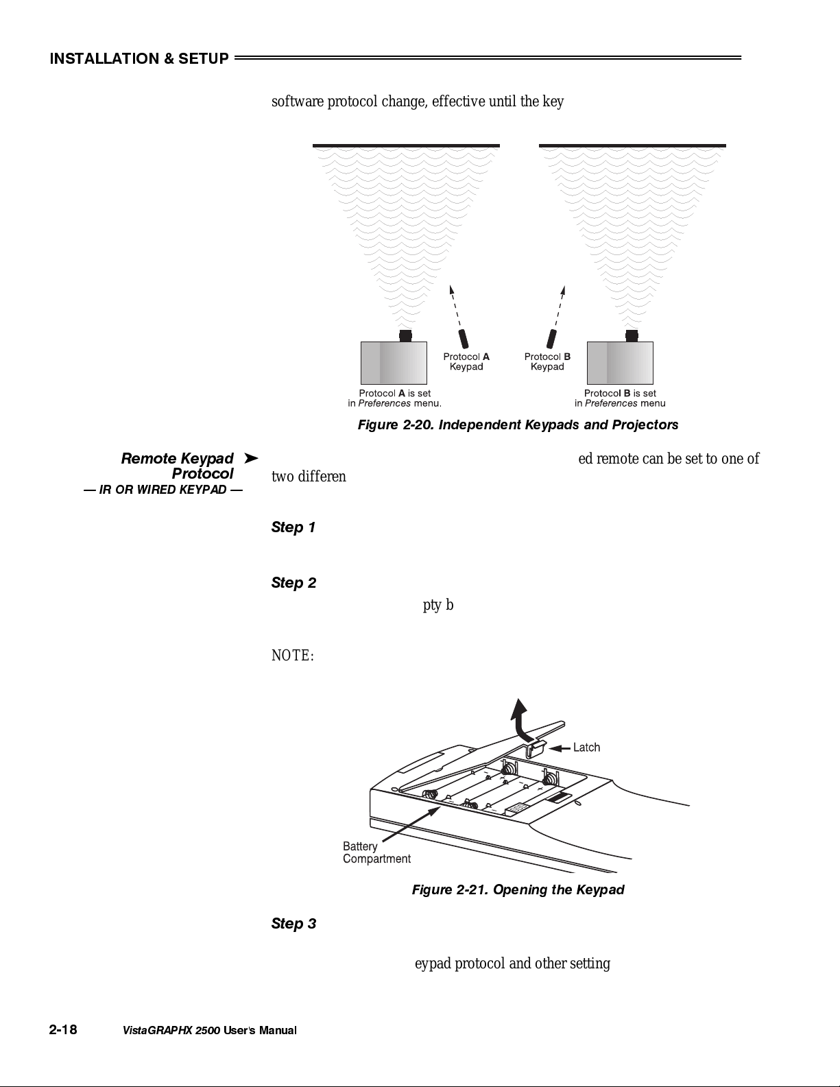
Protocols are most useful for multiple-projector applications. For example, you
might want to change a keypad protocol if you are working with two projectors
and two remote keypads in the same room and need to control each projector
independently (Figure 2-20). When Keypad A has a different protocol than
Keypad B, each keypad communicates only with the projector having a matching
protocol. Or, if you have a network of two or more projectors connected together
via RS-232 serial ports, you may want only certain projectors to respond to a
wired keypad.
NOTE: Matching the protocol on the projector to that of a keypad is done
through a setting in the VistaGRAPHX 2500 Preferences menu. See 3.7,
Adjusting and Checking System Parameters for further information on how to
change the projector's infrared sensor (rear and front) protocol.
A protocol for either type of remote keypad — IR or wired — can be changed
through software commands entered on the keypad. A new protocol set through
software commands remains in effect until the keypad batteries are removed and
replaced (if an IR remote), or until the keypad is unplugged (if a wired remote).
A remote can also be changed manually —you can "hard-wire" new jumper
settings inside the keypad so that they remain in effect until you change the hardwiring. Note that a hard-wired protocol can be temporarily overridden by the
VistaGRAPHX 2500
User's Manual
2-17
INSTALLATION & SETUP
software protocol change, effective until the keypad is unplugged and plugged in
again (if a wired remote) or until a battery is removed (if an IR remote).
Figure 2-20. Independent Keypads and Projectors
Remote Keypad
Protocol
IR OR WIRED KEYPAD
The standard IR remote keypad or the optional wired remote can be set to one of
'
two different protocols — "A" or "B". To hard-wire a protocol to "A" or "B" in
either remote, follow Steps 1 through 5:
Step 1
Unplug the keypad from the projector (applies to wired remote only).
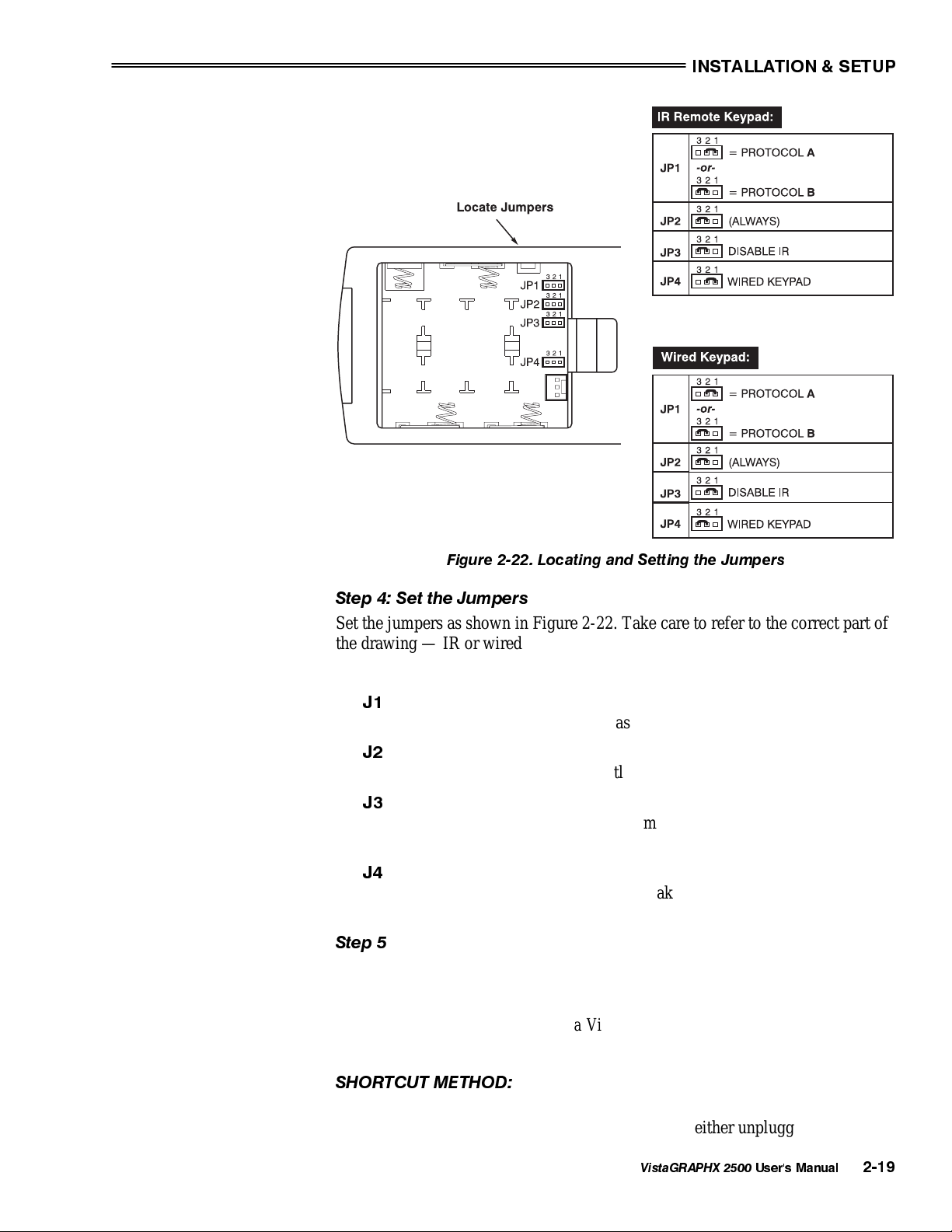
Step 2
Unlatch and open the empty battery compartment on the back of the keypad as
shown in Figure 2-21.
NOTE: A wired keypad will open as shown, but there will be a cable passing
through the battery compartment cover.
2-18
VistaGRAPHX 2500
Figure 2-21. Opening the Keypad
Step 3
Find the 4 jumpers located along the latching side of the battery compartment.
These jumpers set the keypad protocol and other settings so that the keypad
functions in a certain manner.
User's Manual
INSTALLATION & SETUP
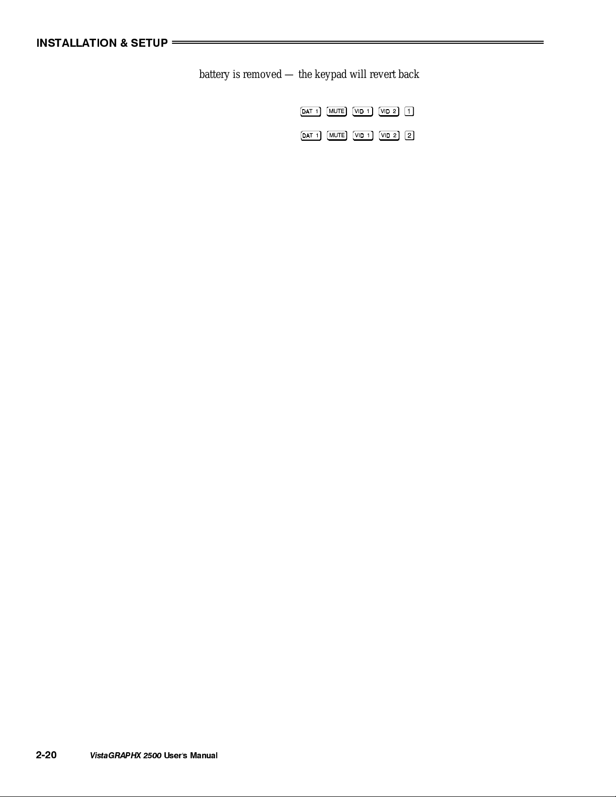
Figure 2-22. Locating and Setting the Jumpers
Step 4: Set the Jumpers
Set the jumpers as shown in Figure 2-22. Take care to refer to the correct part of
the drawing — IR or wired (optional). Use tweezers or needle-nose pliers to
remove and replace each jumper as necessary.
•
J1
jumper: For either remote, set between pins 1 and 2 to set as Protocol
"A". Set between pins 2 and 3 to set as Protocol "B".
•
J2
jumper: For either remote, set between pins 2 and 3 as shown; otherwise,
the projector will not respond correctly to keypad commands.
•
J3
jumper: For the IR remote, make sure that the jumper is set between pins
2 and 3 as shown. For the wired remote, make sure that the jumper is set
between pins 1 and 2 as shown.
•
J4
jumper: For the IR remote, make sure that the jumper is set between pins
1 and 2 as shown. For the wired remote, make sure that the jumper is set
between pins 2 and 3 as shown.
Step 5
Replace battery compartment cover. Plug into projector (wired keypad only) and
test.
NOTE: Although they are similar, a VistaGRAPHX 2500 wired keypad cannot
be converted into an IR remote keypad, nor vise versa.
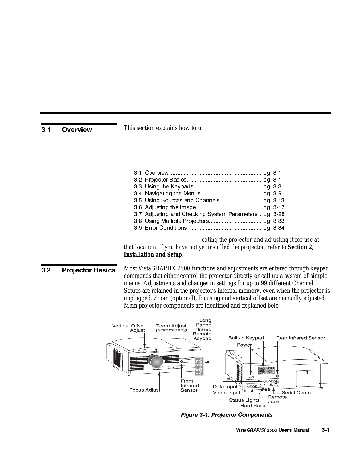
SHORTCUT METHOD:
You can also issue software protocol settings through the keypad. These
software commands will be lost when the keypad is either unplugged or when a
VistaGRAPHX 2500
User's Manual
2-19
INSTALLATION & SETUP
battery is removed — the keypad will revert back to the hard-wired jumper
settings (see above) until you enter the software commands again.
Press
Press
= Protocol "A"
= Protocol "B"
NOTE: If you change any keypad to a new protocol and the projector stops
responding, the projector may be set to a conflicting protocol. Use the
projector's built-in keypad to access the Preferences menu. Under “Front IR
Keypad” or “Back IR Keypad” or "Wired Keypad", select the protocol that
matches the new protocol of the keypad at hand. The projector should now
respond properly.
2-20
VistaGRAPHX 2500
User's Manual
Section 3
Operation
3.1 Overview
3.2 Projector Basics
This section explains how to use the VistaGRAPHX 2500 projector once it has
been installed. Please read through these pages before using the projector for the
first time. An understanding of VistaGRAPHX 2500 features and how to access
them will help you to take full advantage of the capabilities of the projector
within minutes. Organization of this section is as follows:
3.1 Overview...........................................................pg. 3-1
3.2 Projector Basics................................................pg. 3-1
3.3 Using the Keypads ...........................................pg. 3-3
3.4 Navigating the Menus.......................................pg. 3-9
3.5 Using Sources and Channels...........................pg. 3-13
3.6 Adjusting the Image..........................................pg. 3-17
3.7 Adjusting and Checking System Parameters...pg. 3-28
3.8 Using Multiple Projectors..................................pg. 3-33
3.9 Error Conditions ...............................................pg. 3-34
NOTE: Installation involves locating the projector and adjusting it for use at
that location. If you have not yet installed the projector, refer to Section 2,
Installation and Setup.
Most VistaGRAPHX 2500 functions and adjustments are entered through keypad
commands that either control the projector directly or call up a system of simple
menus. Adjustments and changes in settings for up to 99 different Channel
Setups are retained in the projector's internal memory, even when the projector is
unplugged. Zoom (optional), focusing and vertical offset are manually adjusted.
Main projector components are identified and explained below:
Figure 3-1. Projector Components
VistaGRAPHX 2500
User's Manual
3-1
OPERATION
p
Com
onents
INFRARED SENSORS -
'
The infrared (IR) sensors on the front and rear of the
projector receive infrared signals from an IR keypad for remote control of the
projector. For proper operation make sure that these sensors are not blocked.
ZOOM ADJUST -
The lens barrel of a zoom lens (optional) rotates to adjust the
size of the image at the current throw distance (projector-to-screen distance).
Note that minimum and maximum image sizes depend in part on the specific
zoom lens installed (see Section 5, Specifications).
FOCUS ADJUST -
The focus knob adjusts the sharpness of the image at the current
throw distance.
VERTICAL OFFSET ADJUST -
The vertical lens adjustment knob adjusts the vertical
position of the image in relation to the projector lens. See Section 2, Installation
and Setup for details.
COMPOSITE/S-VIDEO INPUT -
Accepts a composite video and S-Video signal from
devices such as VCRs.
RGB INPUT -
SERIAL INTERFACE (WITH LOOP THROUGH) -
Accepts RGB and sync signals from devices such as computers.
Allows one or more projectors to be
remotely controlled by a computer or controller, and provides a communications
connection for
Marquee
and third-party (Extron) signal switchers.
AC LINE CORD INPUT
-
Accepts
only
a special notched AC line cord as supplied
with projector. The projector requires AC power of 100 to 240 VAC, 50 to 60 Hz
@ 11 amps.
WARNING:
Use only the special notched AC line cord. Do not
attempt operation if the AC supply is not within the
specified voltage and power range.
STATUS LEDS -
Two LEDs (light emitting diodes) located to the right of the
Video Input Panel indicate "Status" (top) and "Power" (bottom). During normal
operation, the "Power" light is steady green and the "Status" light flashes green
each time a key is pressed or when the projector receives a serial command. Use
the following chart as a guide:
Status LED Power LED
Off Normal Off Projector is unplugged
Yellow Projector is initializing Yellow Standby power only
Green Flash Key or serial command Green Normal, powered up
Single
Yellow Flash
Continuous
Yellow Flash
Temporary internal
communication failure
Lamp timer: lamp
needs replacing
Red System error: code on Status
LED identifies error
NOTE: A steady red power light accompanied by a coded pattern of red and
yellow flashes from the status light indicates an internal system error. Should the
problem persist, contact a qualified service technician through your dealer or at
Electrohome.
3-2
VistaGRAPHX 2500
User's Manual
OPERATION
3.3 Using the
Keypads
INFRARED REMOTE KEYPAD -
Keypad for controlling the projector from a
distance.
BUILT-IN KEYPAD -
REMOTE JACK -
Alternative location for entering commands.
Accepts a wired remote keypad for remote control of the
projector.
HARD RESET -
Emergency access for powering down the projector in the event
of a system failure. Insert pen point or small screwdriver.
You may use any of three different keypads to control the projector: the IR
remote, the built-in, or the wired remote (optional). Each keypad provides
complete control of the projector, however you may find one keypad more
appropriate than another, depending on your specific installation and application.
On each keypad, some keys cause a direct action (such as
to turn the
projector on or off). Other keys provide access to actions via on-screen menus
and other windows. On the built-in keypad, keys labeled with both a direct
function as well as a number (such as
function (in this case
) unless numeric entry is expected and required to
and ) default to their direct
complete a specific command — there is no separate function key for enabling
direct vs. numerical entry.
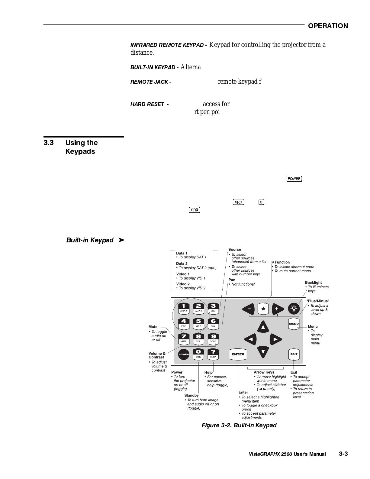
Built-in Keypad
The built-in keypad is located on the back panel of the projector.
'
Figure 3-2. Built-in Keypad
VistaGRAPHX 2500
User's Manual
3-3
OPERATION
yp
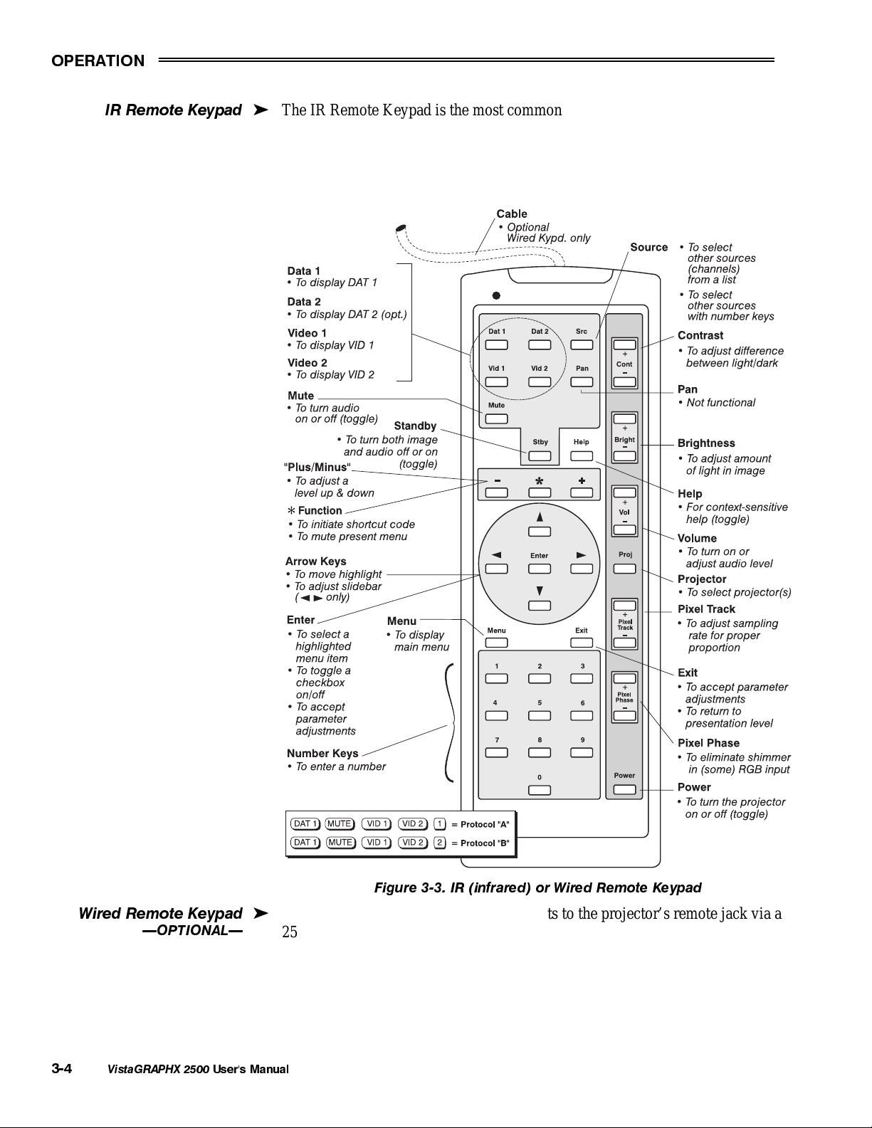
IR Remote Ke
ad
The IR Remote Keypad is the most commonly used keypad. It controls the
'
projector by way of wireless communications from a battery-powered infrared
(IR) transmitter. Use the IR remote keypad the same way you would use a
remote keypad supplied with a TV or VCR. When making key presses, point the
keypad either toward the screen or toward the front or rear of the projector.
Wired Remote Keypad
OPTIONAL
3-4
VistaGRAPHX 2500
'
User's Manual
Figure 3-3. IR (infrared) or Wired Remote Keypad
The optional wired remote keypad connects to the projector’s remote jack via a
25 ft extension cable. It is recommended when:
• the location of the keypad in relation to the projector or screen is inadequate
for IR Remote Keypad operation.
• the lighting conditions are unsuitable for proper IR transmission
OPERATION
yp
• you are controlling multiple projectors in the same room and need to control
each by its own remote keypad.
NOTE: This keypad is identical in appearance and key function to the IR remote
keypad that is standard with the projector. See Figure 3.3
Guide to Ke
ads
The following guidelines apply when using a keypad.
'
Press keys one at a time
1)
You must hold down ,
2)
or
for about a second — for other
keys, a momentary press similar to a mouse click is sufficient.
Press for approximately one second to temporarily illuminate the
3)
backlight for the keys (applies to remote keypads only).
4)
, , , ,
and
repeat their actions when held down. For other
keys, release and press again to repeat an action.
If you press a key while the projector is busy with another action, such as
5)
during power-up, the key press may not take effect.
When you turn on the projector it begins operating at presentation level, such as
an image from the most recently used source signal. The projector temporarily
leaves presentation level when you use the keypad to change control settings,
display menus, or access on-line help. For example, pressing
after startup
displays the main menu of seven triangular icons for access to specific functions
— presentation level is no longer active (although it continues to be displayed
behind the menu). Press
again (or
) to return to presentation level.
Basic keypad commands are explained below.
Keypad operating settings (protocols)
The remote keypad and the optional wired keypad both can store keypad
operating settings (also called protocols) in memory. In some advanced
applications, such as when you want to use two separate keypads to control two
projectors independently, you may want to override the original Vista
GRAPHX
protocol (called "A") set during manufacture. See section 2.10, Keypad
Protocols for complete instructions on changing protocol.
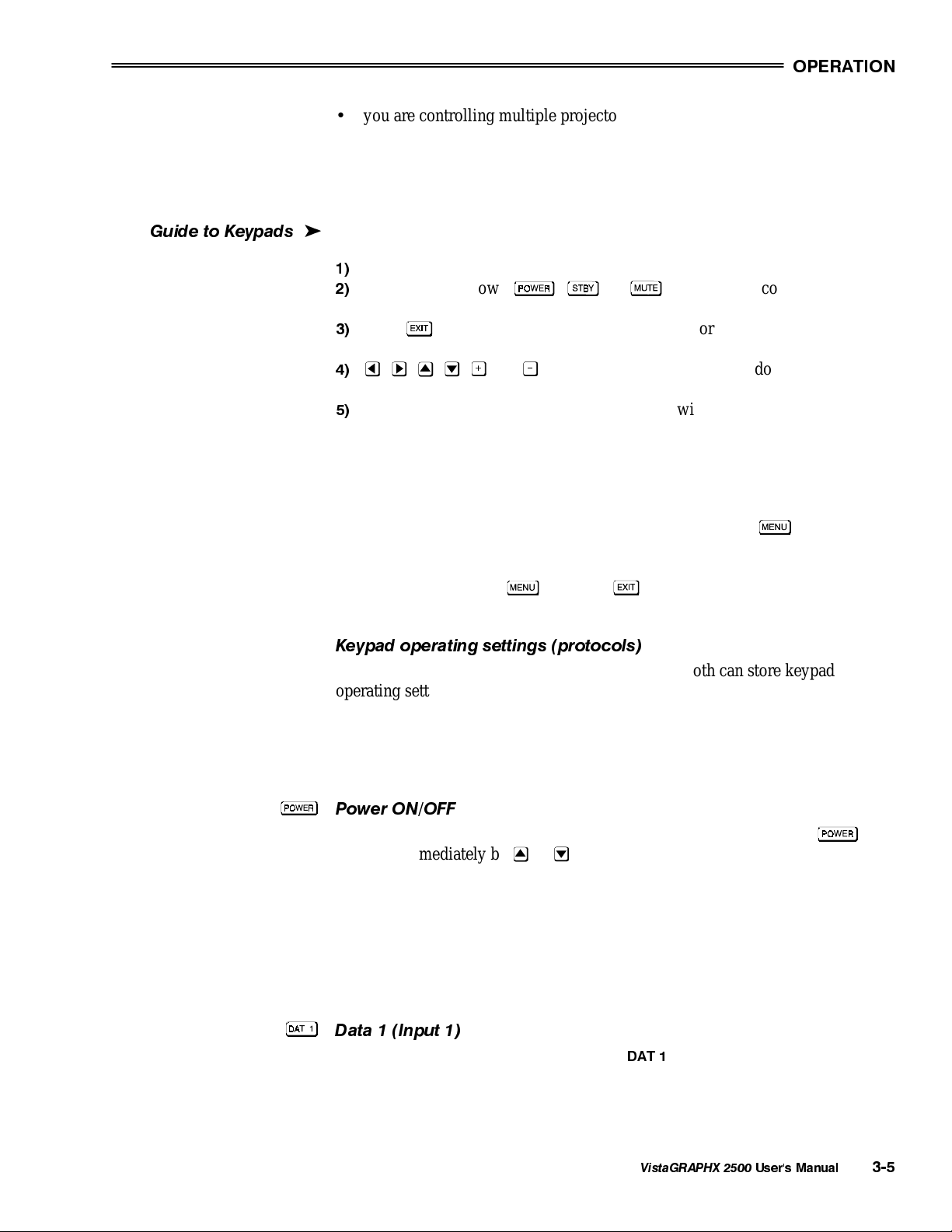
Power ON/OFF
Press/hold for about a second to turn the projector on or off. Or press
followed immediately by
or
if you want to guarantee the correct toggle
(useful if you are unsure of the present status).
NOTES: 1) Whenever the projector is turned off, the lamp cooling fans remain
on for about five minutes to cool the lamp sufficiently. Do not unplug the
projector unless the lamp cooling fans have shut off. 2) Avoid turning a
projector back on until it has been off for at least five minutes. Hot re-strikes of
the lamp reduce lamp life.
Data 1 (Input 1)
on the projector back panel.
Press to select the data input connected to
DAT 1
VistaGRAPHX 2500
User's Manual
3-5
OPERATION
Data 2 (Input 2)
Press to select the optional interface input connected to
DAT 2
on the projector
back panel.
Video 1 (Input 3)
on the projector
Press to select the composite video input connected to
VID 1
back panel.
Video 2 (Input 4)
Press to select the S-video input connected to
on the projector back panel.
VID 2
Source
Press to select a source (channel). Note that the precise method you use to select
sources depends on which option (from within the Preferences menu) you have
chosen for the key. For example, you can choose to see a scrollable list of
channels when you press
, or you may prefer to enter a number representing
a particular channel. See Preferences later in this section.
Standby
Press (and hold for a second or two) to blank the display and mute the audio
output while keeping the projector in a warmed-up and ready state (standby). Or
press
followed immediately by
or
if you want to guarantee the
correct toggle (useful if you are unsure of the present status). Note that all
electronics remain ON even though the image turns to black. To leave standby,
press
again, or .
Menu
Press to display the main menu of seven triangular icons for access to specific
functions, such as Channel List or Size / Position. Press
again (or ) to
return to presentation level.
Enter
Press to select a highlighted item, toggle a checkbox (checked vs. unchecked), or
accept a parameter adjustment and return to the previous menu or image.
Exit
Press
Hold
to save most parameter adjustments and return to presentation level.
for approximately 2 seconds to temporarily illuminate the keypad keys
(IR remote only).
NOTE:
does not save changes within text editing boxes or pull-down lists.
Arrow Keys
Use the
and
scrolling. Also use
TOGGLING WITH
keys (
or
arrow keys to navigate within a menu or pull-down list. Use
to adjust a slidebar level up or down — hold as desired for continuous
and to jump between “pages” in a long pull-down list.
AND
: Use
or
in conjunction with certain
toggle
, , or ) to ensure the correct result. When turning the
projector on, for instance, you may be too far from the projector to know
whether it is really off or it is in standby. If, in this case the projector is simply in
3-6
VistaGRAPHX 2500
User's Manual
standby, when you press and in hopes of turning the projector on, the
projector will actually turn off. Instead, to avoid the risk of toggling in the wrong
direction, quickly press and release the desired toggle key (
within two seconds, immediately press either
(on) or
) and then,
(down) as desired.
The specific toggle will occur.
Contrast
Cont
On either of the remote keypads, select either the
or
"contrast” key to
increase or decrease the difference between light and dark areas of your image.
Use
and until you reach the desired level of contrast, making sure that the
whites remain bright but not distorted or tinted. Note that after 5 seconds of
inactivity the slidebar disappears and you are returned to the previous menu or to
presentation level.
NOTE: On the built-in keypad, select the contrast key and adjust with the arrow
keys. See 3.6, Adjusting the Image (Image Setttings subsection, below).
Bright key
or
On either of the remote keypads, select either the
"bright" key to begin
increasing or decreasing the amount of perceived light in the image so that black
just changes to very dark gray. See 3.6, Adjusting the Image (Image Settings
subsection).
OPERATION
NOTE: The built-in keypad does not have a “Bright” key.
Volume
Vol
On either of the remote keypads, select either the
control the audio level. Use
and until you reach the desired volume. Note
or
"volume” key to
that after 5 seconds of inactivity the slidebar disappears and you are returned to
the previous menu or to presentation level.
NOTE: On the built-in keypad, select the volume key and adjust with the arrow
keys.
Projector
Press
(or
on the built-in keypad) to display an editable box
indicating which projector is currently
listening to the keypad.
To control a single projector, enter the 3-digit
number assigned to the projector you want to
use, or use
or to scroll. Press
To broadcast to multiple projectors, press
keypad) and then
without entering a projector number. Keypad commands
to select.
(or
on the built-in
will then affect all projectors present.
NOTES: 1) The "Broadcast Keys" option in the Preferences menu must be
selected for only one projector in a serial network. The keypad in use must be
OFF (disabled) for the remaining projectors. See 2.10. Keypad Protocols, and
3.7, Adjusting and Checking System Parameters.
VistaGRAPHX 2500
User's Manual
3-7
 Loading...