


8VHU*V# 0DQXDO
7DEOH#RI#&RQWHQWV
6HFWLRQ &RQWHQWV 3DJH
4
5
6
,QWURGXFWLRQ
,QVWDOODWLRQ#)
6HWXS
2SHUDWLRQ
1.1 The Projector.................................................................................................... 1-1
1.2 Components......................................................................................................1-2
1.3 Purchase Record and Servicing........................................................................ 1-2
2.1 Quick Setup...................................................................................................... 2-1
2.2 Installation Considerations............................................................................... 2-2
2.3 Projector Position and Mounting...................................................................... 2-8
2.4 Source Connections........................................................................................ 2-12
2.5 Power Connection.......................................................................................... 2-16
2.6 Operating Orientation..................................................................................... 2-16
2.7 Leveling ......................................................................................................... 2-17
2.8 Zoom, Focus & Vertical Offset...................................................................... 2-17
2.9 Serial Port Connections.................................................................................. 2-17
2.10 Keypad Protocols........................................................................................... 2-21
3.1 Overview.......................................................................................................... 3-1
3.2 Projector Basics ............................................................................................... 3-1
3.3 Using the Keypad............................................................................................. 3-5
3.4 Navigating the Menus.................................................................................... 3-12
3.5 Using Inputs and Channels............................................................................. 3-17
3.6 Adjusting the Image ....................................................................................... 3-21
3.7 Adjusting and Checking System Parameters.................................................. 3-33
3.8 Using Multiple Projectors.............................................................................. 3-39
3.9 Error Conditions............................................................................................. 3-40
7
8
9
87034:4390343#+3;2<<,#³#6RIWZDUH#9HUVLRQ#514
0DLQWHQDQFH
6SHFLILFDWLRQV
$SSHQGLFHV
NOTE: Due to constant research, all information in this manual is subject to change without notice
4.1 Warnings and Guidelines................................................................................. 4-1
4.2 Cleaning........................................................................................................... 4-3
4.3 Replacing Keypad Batteries............................................................................. 4-3
4.4 Replacing the Lamp and Filter......................................................................... 4-4
4.5 Replacing the Lens........................................................................................... 4-9
4.6 Troubleshooting............................................................................................. 4-12
5.1 Specifications................................................................................................... 5-1
A Glossary ...........................................................................................................A-1
B Keypad Reference ...........................................................................................B-1
C Menu Tree........................................................................................................C-1
D Serial Communication Cables..........................................................................D-1
E Throw Distance................................................................................................E-1
F Optional Input Modules ................................................................................... F-1
9LVWD
*5$3+;
#8VHU*V#0DQXDO
#43.
LLL
6HFWLRQ#4
,QWURGXFWLRQ
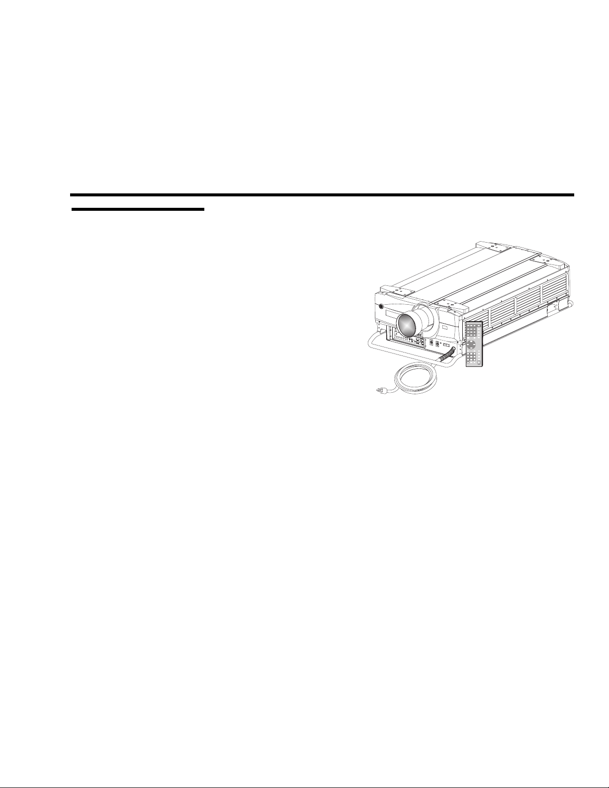
414 7KH#3URMHFWRU
VistaGRAPHX 10K Roadie is a professional-quality DMD projector that uses 3-
chip Digital Light Processing
(DLP) technology from Texas Instruments to
achieve stunning ultra highbrightness multimedia and video
projection. It is a rugged
projector ideal for use in extra
large audience venues, such as
auditoriums, arenas and outdoor
stages. The Vista
GRAPHX 10K
Roadie is compatible with
standard international video
formats and can interface with
IBM-compatible PCs,
Macintosh
computers, and
workstations. Features include:
)LJXUH#4041#9,VWD*5$3+;#43.
◊ up to 10000 ANSI lumens brightness
◊ contrast ratio greater than 160:1 ANSI; over 300:1 full field
◊ 1024 x 768 pixels true resolution, with other resolutions fully scaleable
◊ independent horizontal and vertical size adjustment for custom scaling
◊ interchangeable lenses for diagonal screen sizes up to 40 feet
◊ displays NTSC, PAL and SECAM video input (requires optional decoder)
◊ displays input from PCs, VCRs, laser-disc players, video cameras, etc.
◊ memory for up to 99 custom “channels” (source setups)
◊ intuitive on-screen menus or hidden direct control
◊ identical built-in and remote keypads
◊ controller and switcher compatibility
◊ input switching with keypad
◊ Intelligent Lens System
for automatic recall of lens settings from channel to
channel
◊ built-in RS-232 input for computer control and networked projectors
◊ RS-422 input for extra long distance control
◊ rugged, functional design for harsh environments and secure handling
◊ modular design for easy servicing
+RZ#LW#:RUNV
Vista
ö
GRAPHX 10K accepts data/graphics and video input signals for projection
onto flat or curved front or rear projection screens. High brightness light is
generated by an internal 1.8 kilowatt Xenon arc lamp, then modulated by three
9LVWD
*5$3+;
#8VHU*V#0DQXDO#
#43.
404
,1752'8&7,21
&RQVWUXFWLRQ
DMD (digital micromirror device) panels that provide digitized red, green, or
blue color information. Light from the "ON" pixels of each panel is reflected,
converged and then projected to the screen through a single front lens, where all
pixels are perfectly superimposed as a sharp full-color image.
The projector enclosure is comprised of a combination of metal panels,
ö
extrusions and polymer bezels. Separate access doors and grill panels are easily
removed for quick replacement of the lamp and filter. Modular internal design
provides for ease-of-service and minimal down-time.
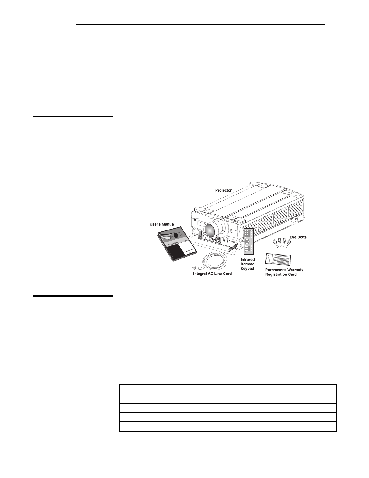
415 &RPSRQHQWV
Included with the standard projector is a built-in keypad, infrared (IR) remote
keypad, integral 30 amp line cord, 4 eye bolts, and a Vista
GRAPHX 10K User's
Manual. Make sure you have all these items, and note that if you have purchased
the projector, a purchaser’s Warranty Registration Card is also included — fill
out this card and return it directly to Electrohome.
NOTE: While the
Vista
GRAPHX
does not include a video decoder module
10K
(optional), this manual assumes that the video decoder is installed.
)LJXUH#4151#
Vista
GRAPHX
#
10K
6\VWHP#&RPSRQHQWV#+ZLWK#/HQV#$GGHG,
416 3XUFKDVH
5HFRUG#DQG
6HUYLFLQJ
405
9LVWD
*5$3+;
8VHU*V#0DQXDO
#43.#
Whether the projector is under warranty or the warranty has expired,
Electrohome's extensive factory and dealer service network is always available.
Electrohome service technicians are fully trained to quickly diagnose and correct
projector malfunctions. Complete service manuals and updates are available to
service technicians for all purchased Vista
GRAPHX
10K projectors.
If you have a problem with the projector and require assistance, contact your
dealer or Electrohome. In many cases, servicing can be performed on site. If you
have purchased the projector, fill out the information below and keep with your
records.
3XUFKDVH#5HFRUG
'HDOHU=
'HDOHU#3KRQH#1XPEHU=
3URMHFWRU#6HULDO#1XPEHU-=
3XUFKDVH#'DWH=
,QVWDOODWLRQ#'DWH/#LI#DSSOLFDEOH=
* NOTE: The projector serial number is on the projector's front identification label.

6HFWLRQ#5
,QVWDOODWLRQ#)#6HWXS
This section explains how to install and set up the projector. If you are familiar with the projector and want to
quickly set it up for temporary use, follow the Quick Setup instructions below. For a more complete setup, follow
the instructions and guides covered in the remaining subsections.
NOTES: 1) The lens for the projector is not mounted when shipped from the factory. For instructions on how to
install or replace a lens, refer to 4.5, Replacing the Lens. 2) This manual assumes the video decoder is installed.
514 4XLFN#6HWXS
67(3#4#
67(3#5#
67(3#6#
Follow these 6 steps for quick temporary setup of the projector.
ö
3RVLWLRQ#WKH#3URMHFWRU
Set the projector at the proper throw distance (projector-to-screen distance) and
vertical position. See 2.3, Projector Position and Mounting and Appendix E.
Make sure that the projector is level from side-to-side (see 2.7, Leveling).
ö
&RQQHFW#D#6RXUFH
Locate the four input panels at the front left corner of the projector. The upper
right panel accepts an RGB input via BNC connectors. The lower left panel
accepts a composite video and S-video input. Connect a source to the appropriate
panel.
ö
&RQQHFW#WKH#/LQH#&RUG#WR#$RZHU
The projector has its own integral 30-amp line cord for connecting to AC. Input
power required is 220 - 240 VAC, 50 to 60 Hz @ 12 amps.
Twist plug to secure.
:$51,1*=
'R#QRW#DWWHPSW#RSHUDWLRQ#LI#WKH#$&#VXSSO\#LV#QRW
ZLWKLQ#WKH#VSHFLILHG#YROWDJH#DQG#SRZHU#UDQJH1
67(3#7#
67(3#8#
ö
7XUQ#WKH#3URMHFWRU#21
3RZH U-
3RZH U-
and hold for a second or two to turn the
21
). Let the projector warm up for about five
Using either keypad, press
projector on (or press
minutes. The Power LED and the AC LED should both glow a steady green.
ö
6HOHFW#D#6RXUFH
Using either keypad, press
,QSXW4, ,QSXW5, ,QSXW6
, or
,QSXW7
to select an d d i s p l a y t h e i ma g e
fo r t h e s o u r c e y o u c o n n e c t e d i n S t e p 2 . I t will resize as needed, producing an image
as large as possible while maintaining the original aspect ratio.
9LVWD
*5$3+;
#8VHU*V#0DQXDO#
#43.
504

,167$//$7,21#)#6(783
67(3#9
ö
$GMXVW#)RFXV#DQG#=RRP
With the input image displayed, press
that should appear, press
(QWHU
to adjust the first double slidebar for focus and
zoom (NOTE: This zoom adjustment requires a Vista
/HQV
on either keypad. In the Lens menu
GRAPHX ILS
zoom lens).
Use the keypad as shown above to focus the image clearly and to increase or
decrease image size (applies to motorized zoom lenses only). If desired, adjust
horizontal or vertical options to shift the image location. Press
done with a double slidebar. To go to the other slidebar, press
(QWHU
. Or simply press the desired option number.
NOTE: If the menu does not appear when you press
/HQV
(QWHU
when you are
or
, the OSD (on-screen
display) has likely been turned off. You can still adjust the options as described,
or press and hold
26'-
for a moment if you want to turn the menu back on.
and press
515 ,QVWDOODWLRQ
&RQVLGHUDWLRQV
/LIWLQJ#DQG#+RLVWLQJ
0HQX
Press
to refine other display parameters. See 3.5, Using Inputs and
Channels if you want to work with other source inputs or defined channels.
Although Vista
GRAPHX
10K delivers a high brightness quality output, the final
display quality could be compromised if the projector is not properly installed.
This subsection discusses issues you should consider before proceeding with a
final installation. Even if you do not intend to use Vista
GRAPHX
10K in a fixed
and permanent installation, this subsection will help you to better understand
what may be done to enhance display performance.
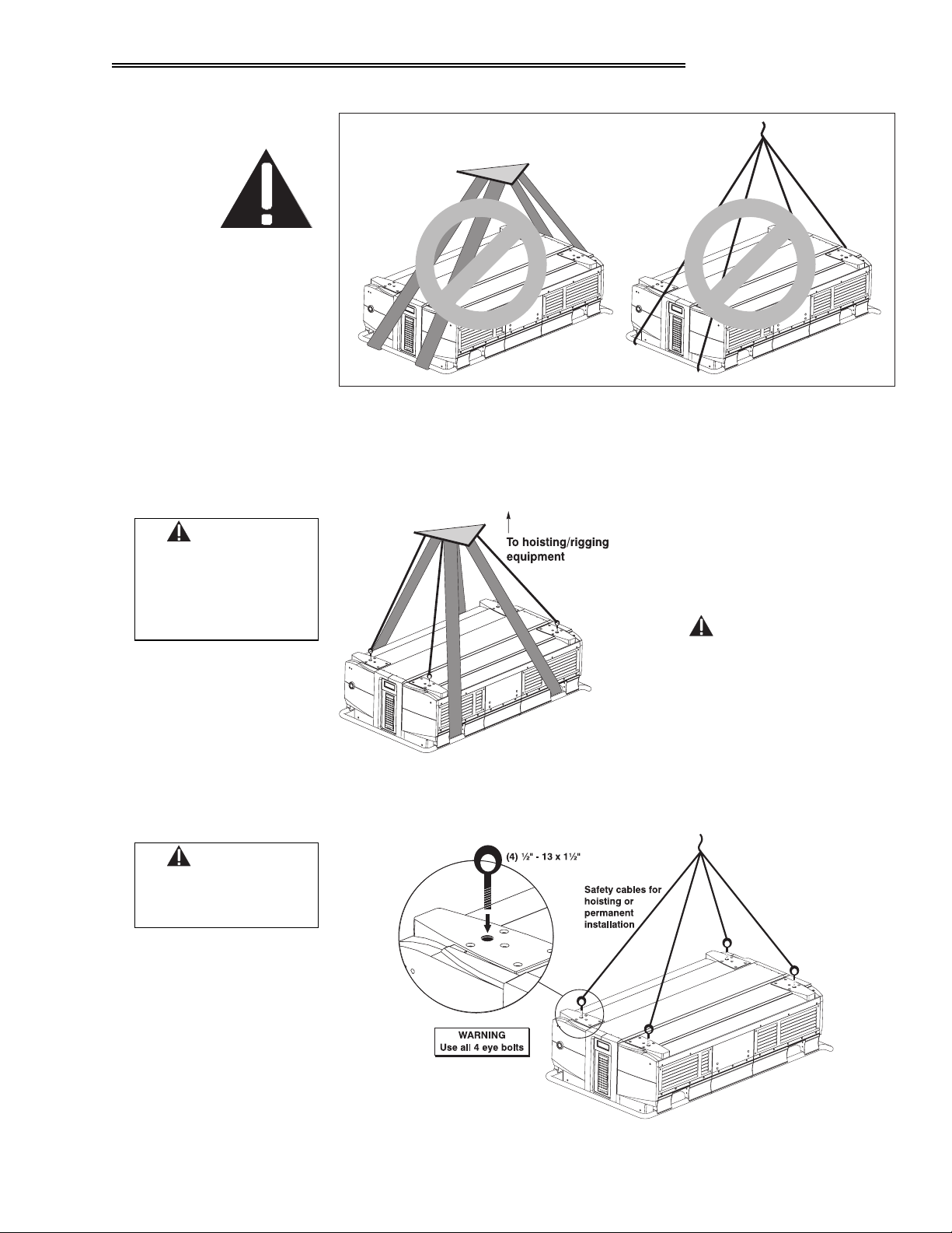
For any new installation, you will likely have to safely lift or hoist the projector
ö
into place. Keep in mind the following guidelines for safety.
8VLQJ#WKH#,QWHJUDO#+DQGOHV
The projector includes integral wrap-around aluminum handles for convenient
grasping. While these handles are adequate for brief hand transport, such as
lifting or carrying over short distances by 2 or more people, the end handles are
not intended to support the entire weight of the projector for extended periods of
time. In particular, do not hoist or suspend the projector from these end handles
or use them in an installation (see Figure 2-1).
505
9LVWD
*5$3+;
8VHU*V#0DQXDO
#43.#
###
:$51,1*
8VH#HQG#KDQGOHV#IRU
EULHI#KDQG#WUDQVSRUW#RQO\1
:$51,1*
#
8VH#VWUDSV#RU#FDEOLQJ
ZLWK#ORDG#FDSDFLW\
DGHTXDWH#IRU#WKH
SURMHFWRU#ZHLJKW1
6HH#SDJH#8061
,167$//$7,21#)#6(783
)LJXUH#5041#'R#QRW#KRLVW#E\#HQG#KDQGOHV
+RLVWLQJ#WKH#3URMHFWRU#LQWR#3ODFH
You can use appropriate nylon webbed strapping and hoisting/rigging equipment
to lift the projector and/or install it as a permanently suspended installation.
Make sure to attach the straps inside
the side handles only, as shown in
Figure 2-2 — do not use the end or
side handles. Hoist only one projector
at a time.
#
,03257$17
5HPRYH#WKH#OHQV#EHIRUH#KRLVWLQJ1
:$51,1*
#
8VH#DW#OHDVW#53#LQ1#OE1
WRUTXH#WR#DWWDFK
H\HEROWV1
)LJXUH#5051#6WUDSV#LQ#3ODFH
suspending it permanently (Figure 2- 3).
)LJXUH#5061#6DIHW\#&DEOHV
Note that the projector also includes
tapped bolt holes in each corner that
accept screw-in eye bolts (provided).
Attach the 4 eye bolts and rig them
with safety cabling whenever you are
hoisting the projector into place or
9LVWD
*5$3+;
8VHU*V#0DQXDO
#43.#
506
,167$//$7,21#)#6(783
,QVWDOODWLRQ#7\SH
Choose the installation type which suits your needs: front or rear screen, floor
ö
mount or inverted mount.
)URQW#6FUHHQ/#)ORRU#0RXQW#,QVWDOODWLRQ
$'9$17$*(6 &216,'(5$7,216
(DV\#WR#VHW#XS
•
&DQ#EH#PRYHG#RU#FKDQJHG#TXLFNO\
•
(DV\#WR#DFFHVV
•
)URQW#6FUHHQ/#,QYHUWHG#0RXQW#+FHLOLQJ,#,QVWDOODWLRQ
$'9$17$*(6 &216,'(5$7,216
'RHV#QRW#WDNH#XS#DXGLHQFH#VSDFH
•
3URMHFWRU#LV#XQREWUXVLYH
•
3URMHFWRU#FDQQRW#EH#DFFLGHQWDOO\#PRYHG
•
5HDU#6FUHHQ/#)ORRU#0RXQW#,QVWDOODWLRQ
$'9$17$*(6 &216,'(5$7,216
3URMHFWRU#LV#FRPSOHWHO\#KLGGHQ
•
3URMHFWRU#LV#HDVLO\#DFFHVVHG
•
8VXDOO\#JRRG#DPELHQW#OLJKW#UHMHFWLRQ
•
5HDU#6FUHHQ/#,QYHUWHG#0RXQW#+FHLOLQJ,#,QVWDOODWLRQ
$'9$17$*(6 &216,'(5$7,216
3URMHFWRU#LV#FRPSOHWHO\#KLGGHQ
•
8VXDOO\#JRRG#DPELHQW#OLJKW#UHMHFWLRQ
•
6KDUHV#IORRU#VSDFH#ZLWK#DXGLHQFH
•
,QVWDOODWLRQ#LV#PRUH#SHUPDQHQW
•
,W#LV#PRUH#GLIILFXOW#WR#DFFHVV#WKH#SURMHFWRU
•
5HTXLUHV#VHSDUDWH#URRP
•
5HTXLUHV#VHSDUDWH#URRP
•
,QVWDOODWLRQ#FRVW#LV#XVXDOO\#KLJKHU
•
6FUHHQ#7\SH
5HDU#6FUHHQ/#)ORRU#0RXQW#ZLWK#0LUURU
$'9$17$*(6 &216,'(5$7,216
3URMHFWRU#LV#FRPSOHWHO\#KLGGHQ
•
8VXDOO\#JRRG#DPELHQW#OLJKW#UHMHFWLRQ
•
5HTXLUHV#OHVV#VSDFH#EHKLQG#VFUHHQ#WKDQ
•
RWKHU#UHDU#VFUHHQ#LQVWDOODWLRQV
Screen type is important when designing a projection system. Inexperienced
ö
5HTXLUHV#VHSDUDWH#URRP1
•
,QVWDOODWLRQ#FRVW#LV#XVXDOO\#KLJKHU
•
users or installers should always consult their dealer when deciding on screen
type. The following guidelines explain the differences between screen types.
)URQW#6FUHHQ#,QVWDOODWLRQV
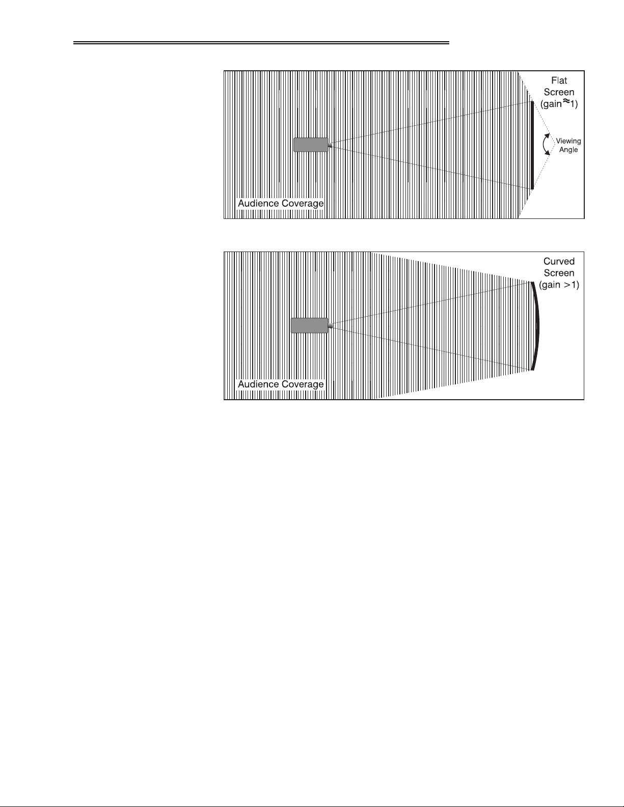
There are two basic screen types: flat and curved. The choice between a flat
screen or a curved screen is dependent on audience viewing angle and screen
gain. There is always a trade-off between viewing angle and gain. Viewing
angles for both screen types are illustrated in Figure 2-4 and Figure 2-5 (plan
views).
Flat screens offer a gain of about 1 with a viewing angle just less than 180°.
Incident light reflects equally in all directions so the audience can see the display
from various angles. Because of the lower gain, flat screens are more effective
when ambient lighting is reduced, although this difference may be negligible
given the ultra high brightness output from this projector.
507
9LVWD
*5$3+;
8VHU*V#0DQXDO
#43.#
,167$//$7,21#)#6(783
)LJXUH#5071#$XGLHQFH#&RYHUDJH#ZLWK#)ODW#6FUHHQ
)LJXUH#5081#$XGLHQFH#&RYHUDJH#ZLWK#&XUYHG#6FUHHQ
Curved screens have gains larger than 1 (due in part to the screen material) and
viewing angles much less than 180°. Most curved screens have different
horizontal and vertical viewing angles. Incident light does not reflect equally in
all directions. The reflected light concentrates in a conical volume or "viewing
cone". Audiences within the viewing cone see a brighter image than that from an
equal area on a flat screen. Audiences outside the viewing cone see a dimmer
image.
NOTE: Vista
GRAPHX
10K lenses are designed primarily for use with flat screens.
However, the projector depth-of-field range allows the lens to be focused on
curved screens as well. Focus remains sharp in the corners, however there may
be significant pincushion distortion, primarily at the top of the screen.
5HDU#6FUHHQ#,QVWDOODWLRQV
There are two basic types of rear screens: diffused and optical. A diffused screen
has a surface which spreads the light striking it. Purely diffused screens have a
gain of less than 1. The main advantage of the diffused screen is its wide viewing
angle, similar to that of a flat screen for front screen projection. Optical screens
take light from the projector and redirect it to increase the light intensity at the
front of the screen. This reduces it in other areas. A viewing cone, similar to that
of a curved front screen installation, is created.
9LVWD
*5$3+;
8VHU*V#0DQXDO
#43.#
508

,167$//$7,21#)#6(783
6FUHHQ#6L]H
To summarize, optical screens are better suited for brightly lit rooms where the
audience is situated within the viewing cone. Diffused screens are best suited
when a wide viewing angle is required but there is low ambient room lighting.
Screen size may be from 6 to 40 feet diagonal, depending on the lens you are
ö
using. For instance, a 1:1 lens produces a 6-30 foot image size, whereas a 4-7:1
zoom lens produces a 10-40 foot image size. Choose a screen size which is
appropriate for your lens and application. Keep in mind that if the projector will
be used to display text information, the image size must allow the audience to
recognize all text clearly. The eye usually sees a letter clearly if eye-to-text
distance is less than 150 times the height of the letter. Small text located too far
from the eye may be illegible at a distance no matter how sharply and clearly it is
displayed.
To fill a screen with an image, the aspect ratio of the screen should be equal to
the aspect ratio of the image. The aspect ratio of an image is expressed as the
ratio of its width to its height. Standard video from a VCR has a 4:3 or 1.33:1
aspect ratio. For example, to display a VCR output with a 4:3 aspect ratio onto a
10 foot (3m) high screen, the width of the screen must be at least 13.3 feet (4m).
Note: Screen size is often specified as diagonal size. Screens specified by
diagonal size have aspect ratios of 4:3. Screens with other aspect ratios are not
typically specified by diagonal size.
,GHDO#5RRP#/LJKWLQJ
The high brightness output of Vista
ö
GRAPHX
10K is certainly well suited for
locations where ambient lighting is less than optimum for projection, but there
are still many simple things you can do to optimize your installation.
Visiting a movie theater can give you an idea of what makes an ideal projection
environment. Walls, floors and furnishings are dark and matte finished. A
projection room should not have white reflective ceilings or non-directional
lighting such as fluorescent lights. The white ceiling spreads light, making the
room appear brighter. Keep lighting and reflections to a minimum.
If it is not possible to eliminate fluorescent lights, consider using incandescent
spot lighting or parabolic reflectors ("egg crates") to direct light down to the
floor. Light dimmers or rheostats allow further control.
Outside windows are undesirable in any projection room. A small crack between
curtains on a sunny day can wash out a projected image. If you do have
windows, make sure that window coverings are opaque and overlapping — some
window coverings are designed to provide up to 100 percent blockage of outside
light. Ideally, the material should have a matte finish.
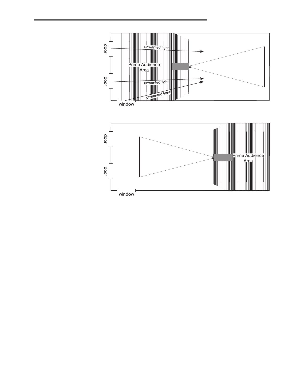
To minimize the effects caused by unwanted light from door and aisle ways,
carefully choose the position of your projector and screen. Figure 2-6 shows an
installation where poor screen placement allows too much unwanted light to
enter the screen. In Figure 2-7, the screen and the projector are positioned so that
unwanted light is minimized.
509
9LVWD
*5$3+;
8VHU*V#0DQXDO
#43.#
,167$//$7,21#)#6(783
)LJXUH#5091#3RRU#6FUHHQ#3ODFHPHQW
2WKHU#&RQVLGHUDWLRQV
)LJXUH#50:1#%HWWHU#6FUHHQ#3ODFHPHQW
Even with all lighting removed it is still possible that room reflections within the
room can slightly degrade the image. Light from the projection screen should be
absorbed by the ceilings, walls and floors so that it will not be reflected back to
the screen. Again, keep reflective surfaces to a minimum.
Here are some other considerations and tips which can help you improve your
ö
installation:
• Ventilation is an important factor when preparing a projection room. The
ambient temperature should be kept constant and below 35°C (95°F). Keep
the projector away from heating and/or air conditioning vents. Changes in
temperature can cause drifts in the projector circuitry which may affect
performance.
• Keep the projector away from devices which radiate electromagnetic energy
such as motors and transformers. Common sources of these are slide
projectors, speakers, power amplifiers, elevators, etc.
• For rear screen applications, less space is required if a mirror is used to fold
the optical path.
• Choose the right screen size for the application:
9LVWD
*5$3+;
8VHU*V#0DQXDO
#43.#
50:
,167$//$7,21#)#6(783
◊ As screen size increases, magnification increases which reduces
brightness. Select a screen size which is appropriate for the venue,
but not larger than that required.
◊ Installing a large screen in a small room is similar to watching
television close up; too large a screen can overpower a room. A good
rule of thumb is to be no closer than 1.5 times the width of the
screen.
◊ Larger screens require greater attention to lighting conditions.
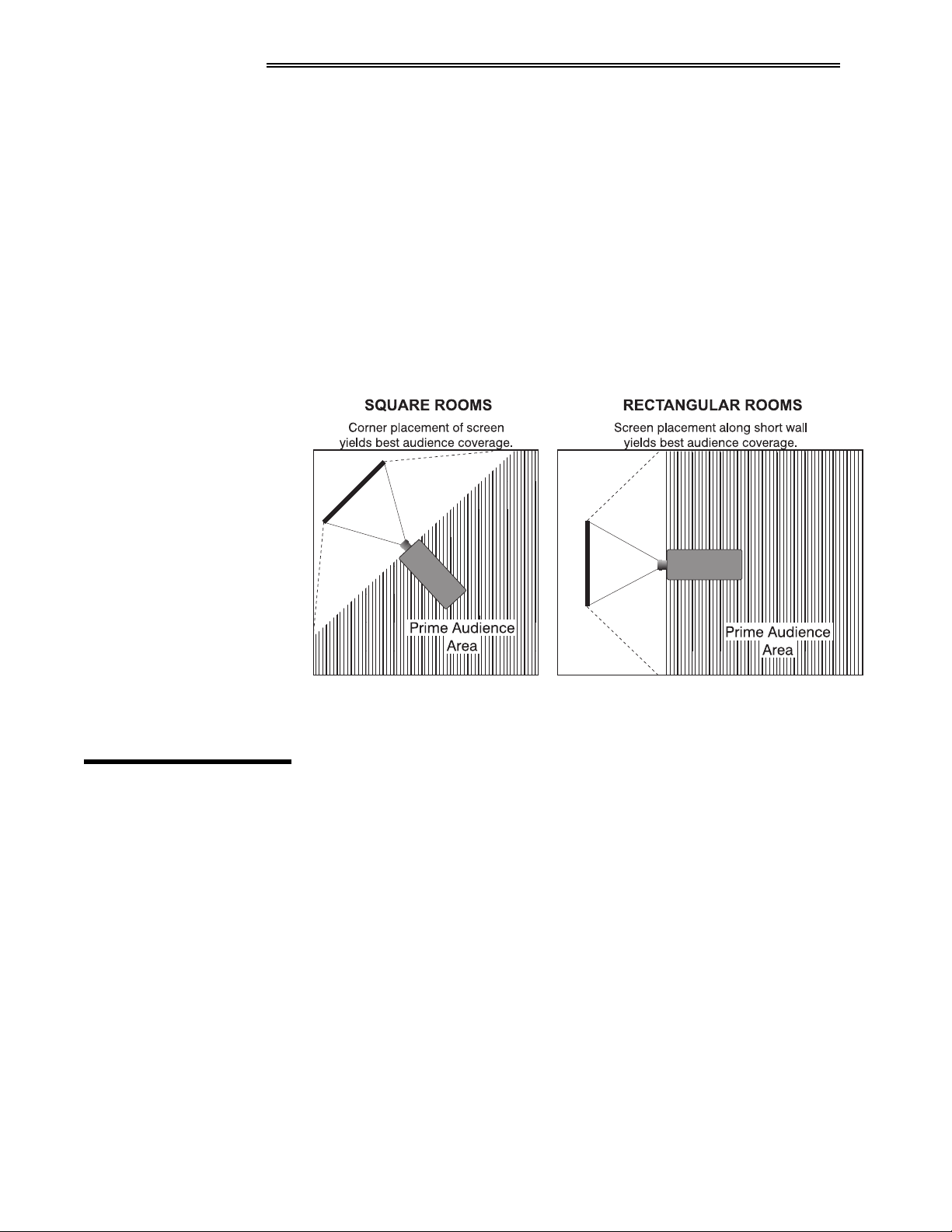
• When laying out the projection room, consider positioning the projector and
screen in a manner which will achieve maximum audience coverage and
space efficiency. For example, placing the screen along the larger wall in a
rectangular room will reduce audience coverage. Figure 2-8 shows two
examples of how audience coverage is maximized.
516 3URMHFWRU
3RVLWLRQ
DQG#0RXQWLQJ
7KURZ#'LVWDQFH
)LJXUH#50;1#6FUHHQ#/RFDWLRQV#IRU#0D[LPXP#$XGLHQFH#&RYHUDJH
Installation type, screen type, and lighting all affect where the projector is
positioned. In addition, both throw distance (the distance between the projector
and screen) and vertical position (the height of the projector in relation to the
screen) must be determined for every new installation. Both depend on the
screen size and projector lens type you are using. Make sure that the room can
accommodate the required position of the projector for the chosen screen size.
Throw distance is the distance between the projector's front feet and the screen.
ö
It is measured perpendicular to the lens surface and screen surface. As you move
the projector farther from the screen, the image becomes larger.
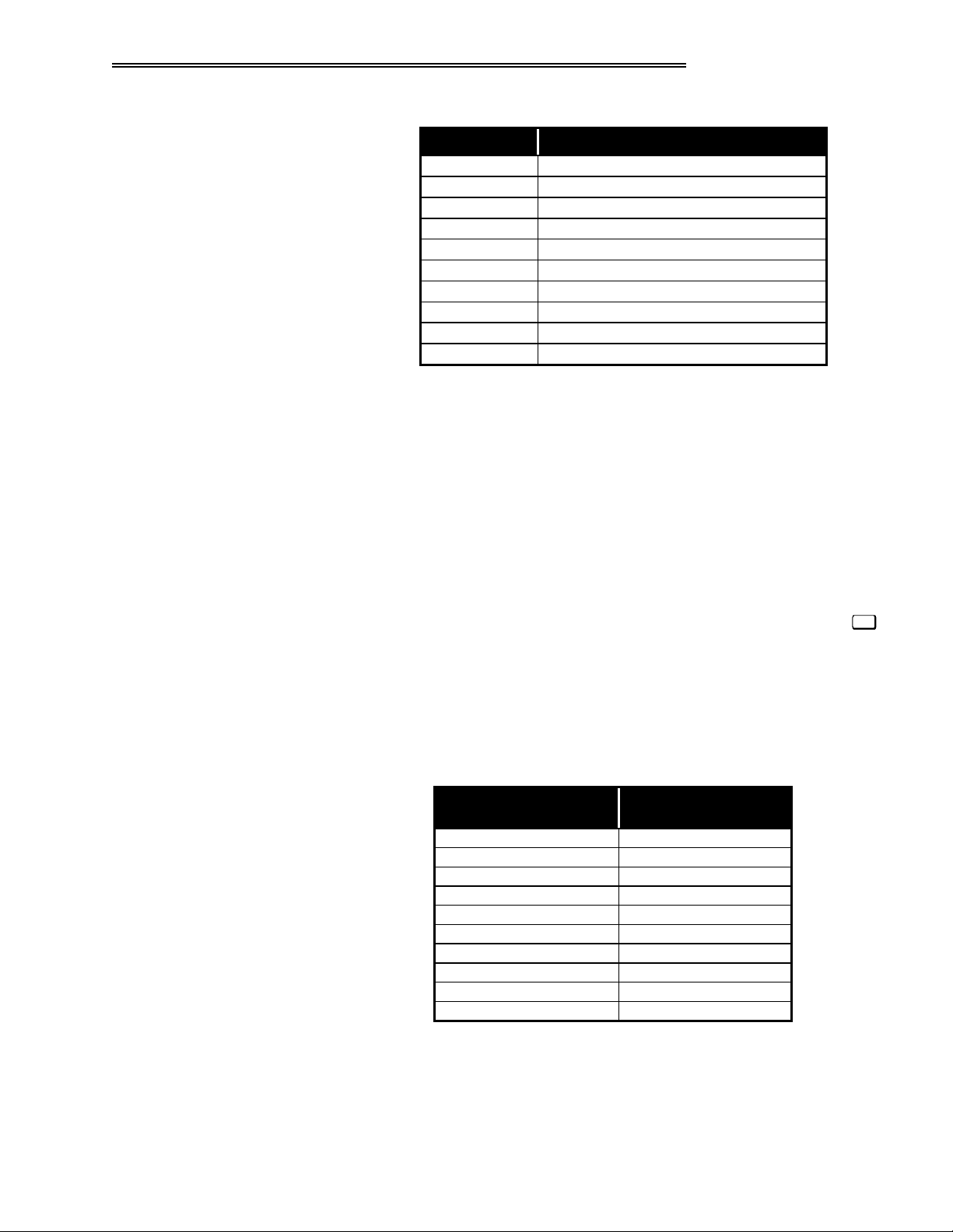
Throw distance is roughly equal to the horizontal width of the screen multiplied
by the type of lens you are using. For example, if you are using a 3.9:1 lens,
throw distance should be approximately 3.9
[
the screen width. Once you know
your screen size, you can estimate how far away the projector should be, as
shown in Table Chapter 2 -1.
,03257$17=
For exact placement in an
installation, always refer to the throw distance formula and/or graph for your
lens as listed in Appendix E.
50;
9LVWD
*5$3+;
8VHU*V#0DQXDO
#43.#
,167$//$7,21#)#6(783
7DEOH#&KDSWHU#5#041#$SSUR[LPDWH#7KURZ#'LVWDQFHV
/HQV#7\SH $SSUR[LPDWH#7KURZ#'LVWDQFH
31;=4 31;#[#KRUL]RQWDO#VFUHHQ#ZLGWK
4=4 4#[#KRUL]RQWDO#VFUHHQ#ZLGWK
516=4 516#[#KRUL]RQWDO#VFUHHQ#ZLGWK
61<=4 61<#[#KRUL]RQWDO#VFUHHQ#ZLGWK
818=4 818#[#KRUL]RQWDO#VFUHHQ#ZLGWK
415#0#516=4 IURP#415#WR#516#[#KRUL]RQWDO#VFUHHQ#ZLGWK
418#0#518=4 IURP#418#WR#518#[#KRUL]RQWDO#VFUHHQ#ZLGWK
518#0#7=4 IURP#518#WR#7#[#KRUL]RQWDO#VFUHHQ#ZLGWK
516#0#818=4 IURP#516#WR#818#[#KRUL]RQWDO#VFUHHQ#ZLGWK
7#0#:=4 IURP#7#WR#:#[#KRUL]RQWDO#VFUHHQ#ZLGWK
127(=#6HH#7DEOH#505#IRU#RULJLQDO#9LVWD3UR#OHQV#PRGHO#HTXLYDOHQWV1
NOTES: 1)While throw distance is measured perpendicular to the screen and
projector, this measurement is not necessarily parallel to the floor — both
projector and screen may be inclined together. 2) It is good practice to simulate
the setup with the projector fully warmed-up to determine the precise throw
distance required. 3) Always use the throw distance information from Appendix E.
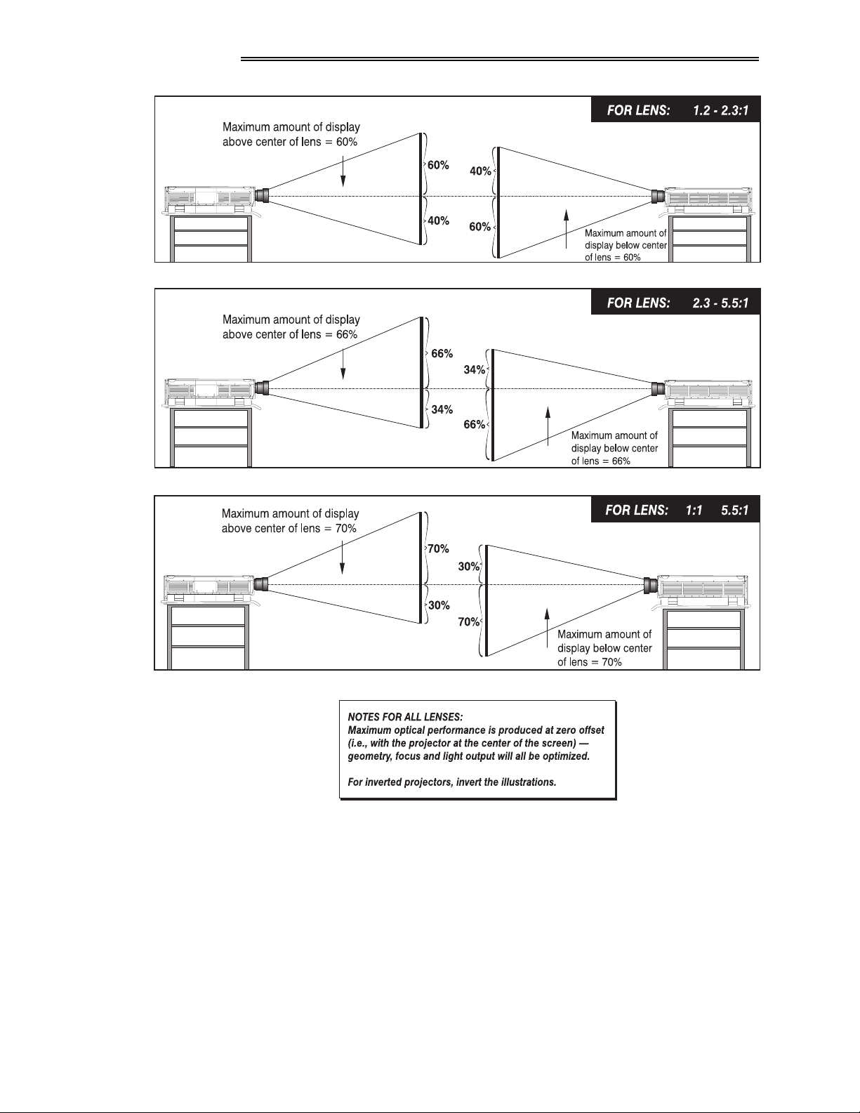
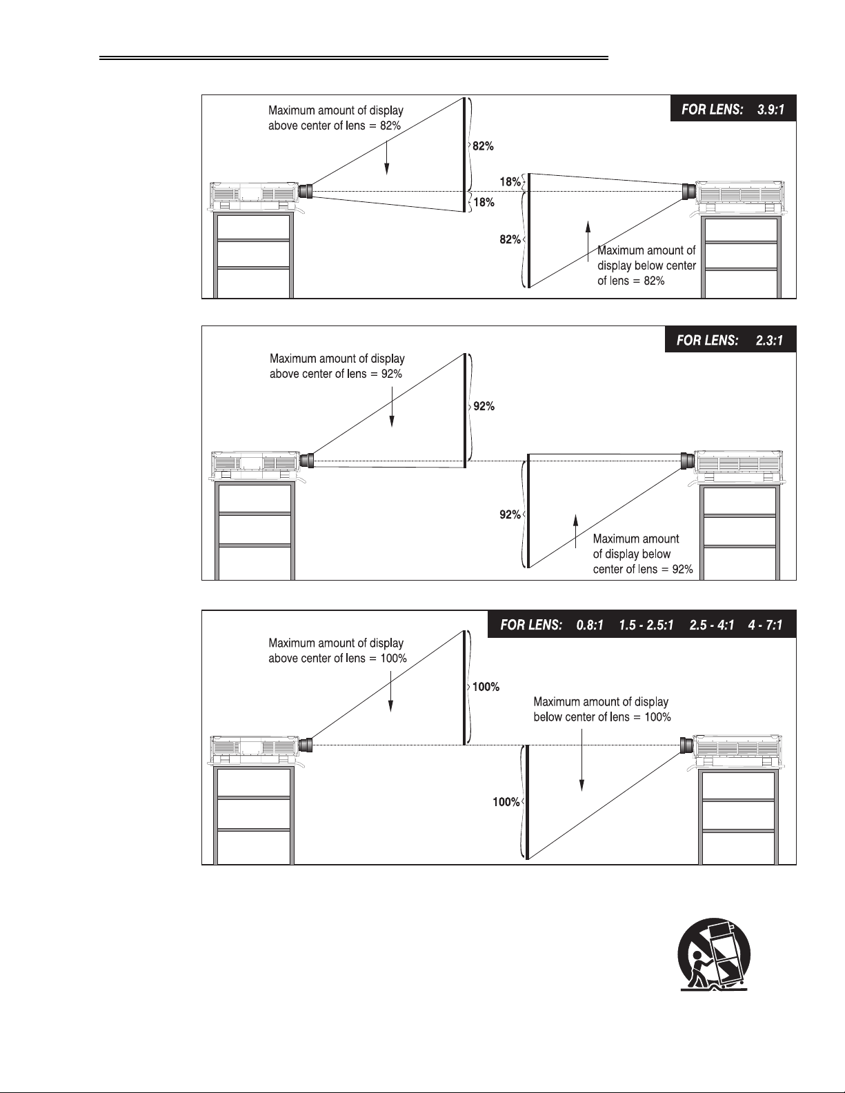
9HUWLFDO#3RVLWLRQ
The vertical position of the projector in relation to the screen also depends on the
ö
size of the screen and the lens type. Correct vertical position ensures that the
image will be rectangular in shape rather than keystoned (having non-parallel
sides) and that image focus and brightness both remain optimized.
Vertical position is offset—that is, the image can be moved—by using the
key. This displays the Lens menu, where both horizontal and vertical offset can
be adjusted with slidebars. Note that the range of adjustment depends on the lens
type you are using. See Table Chapter 2 -2 for the number of pixels by which
you can move an image using a specific lens. Refer to Figure 2-9 to see more
clearly how the pixel offset ranges affect the placement of your image in relation
to the vertical position of the projector.
7DEOH#&KDSWHU#5#051#2IIVHWV/#LQ#3L[HOV
/HQV#7\SH 0D[LPXP#5HFRPPHQGHG
31;=4 “#6;7
4=4#
+9LVWD3UR#415=4,
516=4#
+9LVWD3UR#6=4,
61<=4#
+9LVWD3UR#8=4,
818=4#
+9LVWD3UR#:=4,
415#0#516=4#
418#0#518=4 “#6;7
518#0#7=4 “#6;7
516#0#818=4#
7#0#:=4 “#6;7
+9LVWD3UR#41806=4,
+9LVWD3UR#60:=4,
2IIVHW#+LQ#3L[HOV,
“#483
“#658
“#583
“#483
“#;3
“#458
/HQV
NOTES: 1) If you cannot raise or lower the image enough for your installation,
or if the image becomes keystoned or exhibits uneven brightness, the projector is
probably too high or low in relation to the screen. 2) Recommended offset
ranges can be exceeded, however this may affect image quality. 3) Simultaneous
horizontal
offset can limit the range of vertical offset.
9LVWD
*5$3+;
8VHU*V#0DQXDO
#43.#
50<
,167$//$7,21#)#6(783
5043
9LVWD
*5$3+;
8VHU*V#0DQXDO
#43.#
,167$//$7,21#)#6(783
0RXQWLQJ
)LJXUH#50<1#9HUWLFDO#2IIVHW#5DQJHV
For typical front or rear floor mounts, mount the projector on a
ö
secure table or cart. Take care with a mobile cart—avoid sudden
stops, excessive force and uneven surfaces that may cause the
projector and cart combination to overturn.
9LVWD
*5$3+;
8VHU*V#0DQXDO
#43.#
5044
,167$//$7,21#)#6(783
The table or cart should be reasonably level. Fine adjustments to the projector
level can be made by adjusting the height of the projector legs; refer to 2.7,
Leveling for details.
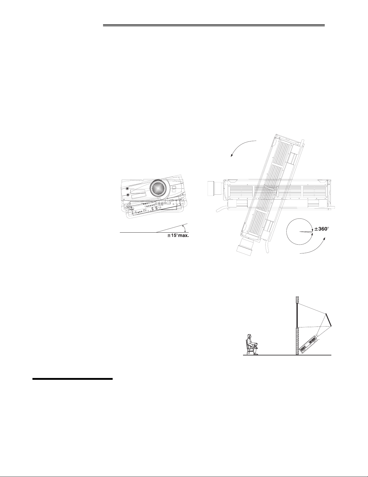
6SHFLDO#0RXQWLQJ
Note that Vista
GRAPHX
10K can be rotated and mounted at any vertical angle-i.e.,
you can tilt the projector forwards or backwards as much as desired for your
application. The side-to-side tilt, however must not exceed 15° (see Figure 2-10).
This limit ensures that the arc lamp in the projector operates properly and safely.
Always make sure that exhaust air from the projector does not vent towards the
lens, otherwise you may detect heat waves in your projected image.
)ROGHG#2SWLFV
517 6RXUFH
&RQQHFWLRQV
)LJXUH#50431#9HUWLFDO#DQG#+RUL]RQWDO#7LOW#5DQJHV
You must use an Electrohome ceiling mount fixture if the projector is to be
inverted and suspended. For more information, contact your dealer.
In rear screen applications where space
ö
behind the projector is limited, a mirror
may be used to fold the optical path. See
Figure 2-11. The position of the projector
and mirror must be accurately set — if
considering this type of installation, call
your dealer for assistance.
)LJXUH#50441#)ROGHG#2SWLFV
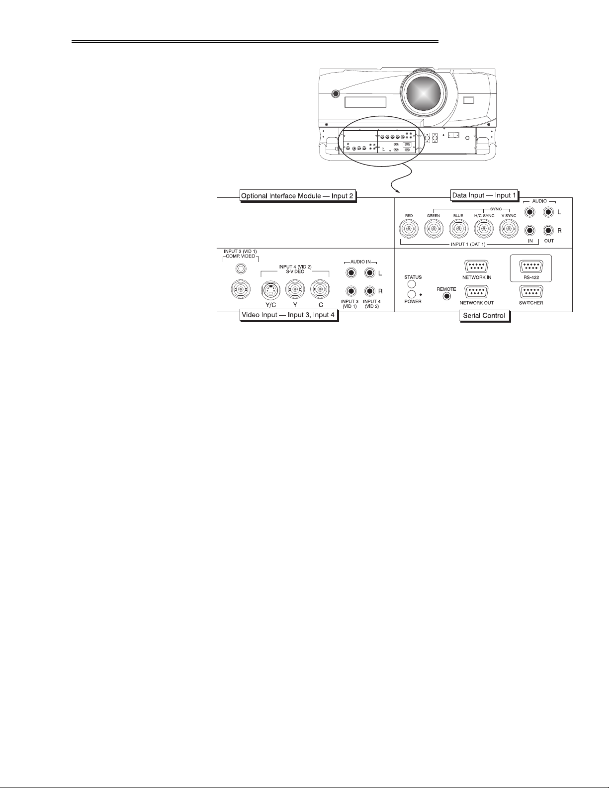
The front panel of the projector has two standard input panels to which you may
connect a variety of sources. The upper right panel (Input 1) accepts an RGB
input from an external RGB source with audio follow-through. The lower left
panel (if video decoder module is installed) accepts composite video (Input 3) or
S-video (Input 4) and audio from devices such as video tape or disk players.
There are also several optional interfaces available for connecting other sources
(Input 2). Such an option installs in the upper left panel. See Figure 2-12.
5045
9LVWD
*5$3+;
8VHU*V#0DQXDO
#43.#
,167$//$7,21#)#6(783
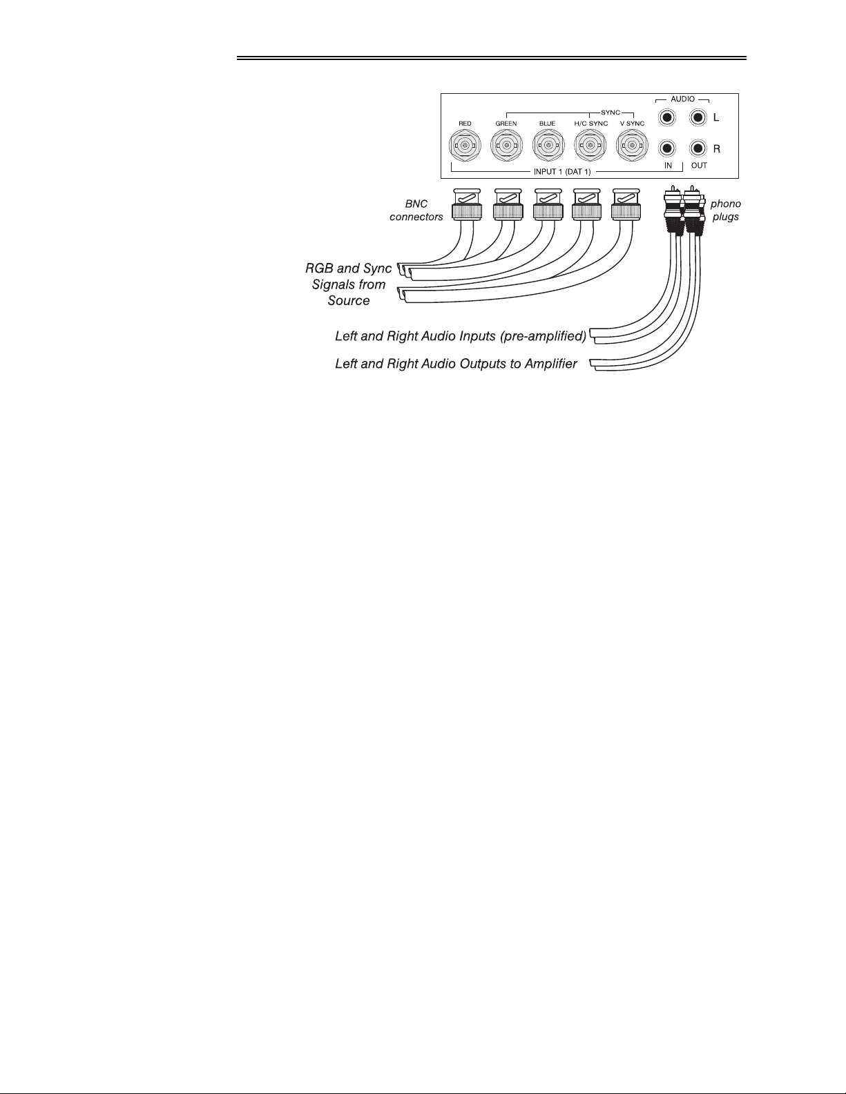
5*%#,QSXW
)LJXUH#50451#9LVWD
The RGB input (Input 1) includes BNC type connectors for connection to a
ö
*5$3+;
#43.#)URQW#3DQHO
variety of RGB sources. Such sources include VGA, SVGA, XGA, Mac,
PowerMac, DEC, Sun, SGI and others. Vista
GRAPHX
10K supports multiple sync
types: sync-on-green for data, composite, and separate H & V.
NOTE: Depending on the source, you may need a custom adapter cable that has
BNC connectors at the projector end and different type of connector at the other
(such as a 15-pin "D" connector for computer sources). Contact your dealer.
Connect the sync BNC input(s) first. Then connect the red, green and blue
source outputs to the RED, GREEN, and BLUE inputs on the panel. If the source
uses sync-on-green, only the red, green, and blue connections are required. If the
source provides a composite sync output, connect it to the H/C SYNC input. If
the source provides separate horizontal and vertical sync outputs, connect
horizontal sync to the H/C SYNC input and connect vertical sync to the V SYNC
input. See Figure 2-13.
Connect component video as follows:
to "
Y
(also called B-minus-Y) to "
U
(also called R-minus-Y) to "
V
Green
"
"
Blue
"
Red
NOTES: 1)
When using YUV video, you must specify this signal type within the
Settings
menu so that the projector can distinguish between this signal and other
RGB sources. See
GRAPHX
Vista
10K
3.6, Adjusting the Image
does not automatically recognize a YUV signal.
Image
. 2) For best performance, do not
connect HDTV signals to Input 1 — this type of source requires the HDTV Input
Module (available as an option).
9LVWD
*5$3+;
8VHU*V#0DQXDO
#43.#
5046
,167$//$7,21#)#6(783
)LJXUH#50461#5*%#,QSXWV
To control audio levels in an audio/visual system, connect pre-amplified (line
level) audio inputs to the left and right channel audio inputs on the Input 1 panel.
Then connect the audio outputs to external audio amplification equipment for
sound output. All audio connection cables require standard RCA type phono
plugs.
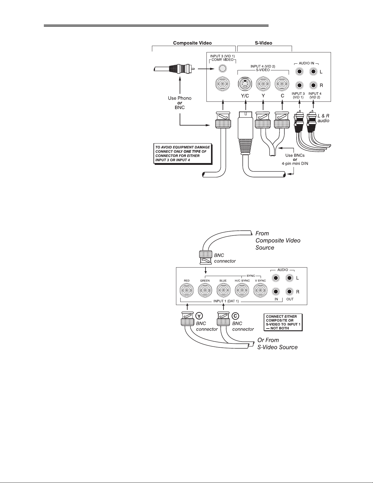
&RPSRVLWH#9LGHR
DQG#609LGHR#,QSXW
The Composite/S-Video input provides simultaneous connection of both a
ö
composite video source (Input 3) and an S-Video source (Input 4).
If connecting a S-Video source, use the 4-pin mini DIN connector or the Y and C
BNC connectors (luminance and chrominance) — do not use both as input. If
connecting a composite video source, use the Composite BNC connector or the
RCA phono jack — do not use both as input. See Figure 2-14.
NOTE: If using the loop-through feature for composite or S-Video input, see
"Video Termination" in
3.7, Adjusting and Checking System Parameters
.
5047
9LVWD
*5$3+;
8VHU*V#0DQXDO
#43.#
,167$//$7,21#)#6(783
)LJXUH#50471#&RPSRVLWH#DQG#609LGHR#,QSXWV
If you want to use an extra video source in addition to the video source(s)
connected at Inputs 3 and 4, connect either a Composite or S-Video source to
Input 1 as shown in Figure 2-15.
2WKHU#,QSXWV
)LJXUH#50481#&RQQHFWLQJ#D#9LGHR#6RXUFH#WR#,QSXW#4
Electrohome Optional Input Modules allow you to increase the total number of
ö
inputs and to accommodate other signal types. These modules may be installed
in the upper left section of the control panel on the front of the Vista
(called Input 2). They are:
• RGB Input Module
• RGB Loop Thru Module
• Composite/S-Video Module
• HDTV Input Module
9LVWD
*5$3+;
8VHU*V#0DQXDO
#43.#
GRAPHX
10K
5048
,167$//$7,21#)#6(783
• PC Analog Input Module
518 3RZHU
&RQQHFWLRQ
• Vista Digital Input Module
(available Fall ’98)
NOTES: 1) Installation of optional interfaces must be done by qualified service
personnel only — contact your dealer. 2) See
Modules
for a brief description of each interface.
Appendix F, Optional Input
Plug the twist-locking three-prong end of the integral AC line cord (30 amp, with
L6-30 plug) in a matching grounded AC outlet.
Twist to secure
. Input voltage to
the projector must be between 220 and 240 VAC, 50 or 60 Hz. The power source
must be capable of supplying 2800 watts (15 amps) of power to the projector.
#
:$51,1*
#
#'R#QRW#DWWHPSW#RSHUDWLRQ#LI#WKH#$&#LQSXW#LV#QRW#ZLWKLQ
WKH#VSHFLILHG#LQSXW#UDQJH1
:$51,1*
#
7KH#SOXJ#SURYLGHG#LQFOXGHV#D#WKLUG#SLQ#DV#D#JURXQG1
'R#QRW#RSHUDWH#XQOHVV#WKH#JURXQG
FRQQHFWLRQ#LV#LQWDFW1
Caution:
#
Once the projector is turned off, the lamp cooling fans will
continue to run for approximately five minutes to ensure that the projector and
lamp have sufficiently cooled, at which point the fans will automatically shut off.
To avoid thermal stress to lamp, never unplug the line cord while the lamp
cooling fans are running. Do not unplug the projector or use the circuit breaker
switch in order to power down.
519 2SHUDWLQJ
2ULHQWDWLRQ
5049
9LVWD
*5$3+;
8VHU*V#0DQXDO
#43.#
GRAPHX
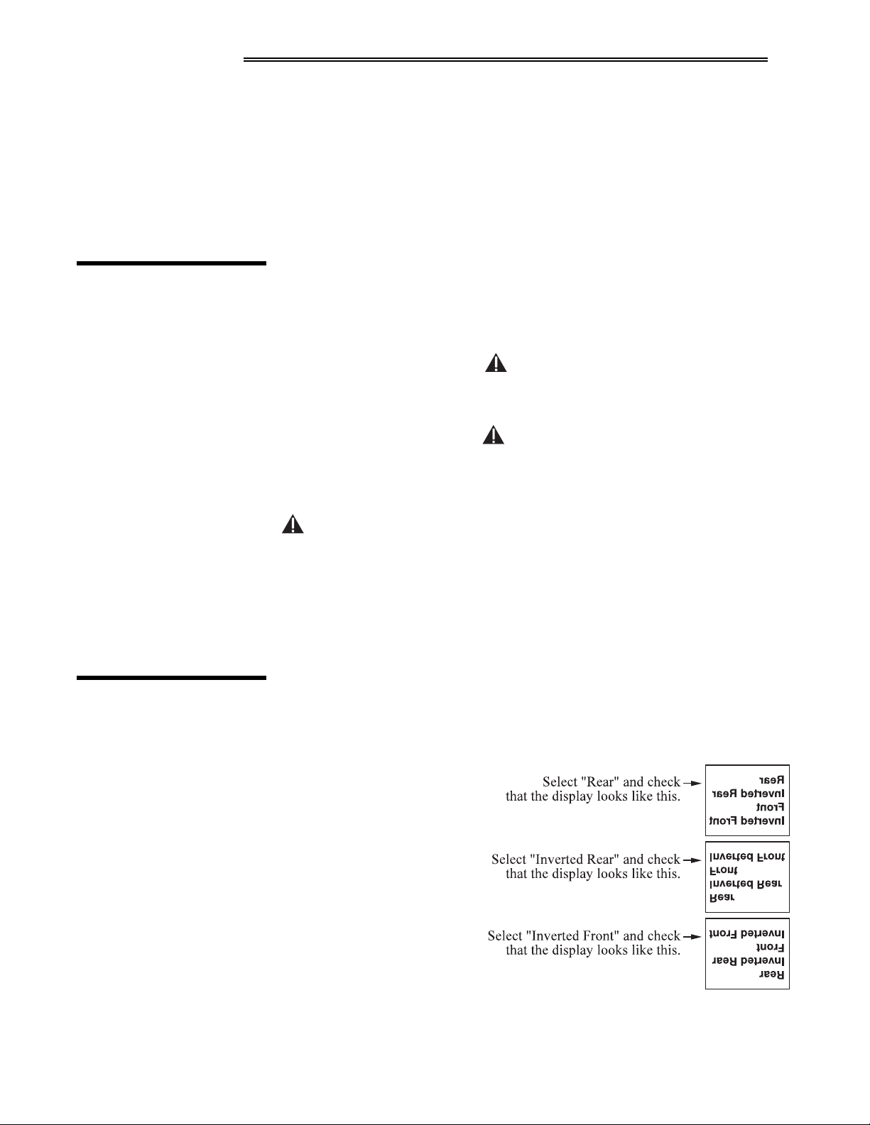
Vista
10K is set up at the factory for use in a front screen, floor mount
orientation. If the installation is ceiling mount or rear screen, you may notice that
displayed images are upside down and/or reversed. To correct, you must change
the image orientation from within the Preferences menu (you may prefer to do
this before physically
installing the projector). See
Section 3, Operation for
further information.
In the Preferences menu,
highlight and select the
"Image Orientation" pulldown list. From a front
screen floor mount
installation, select from Rear,
Inverted Rear, Front or
Inverted Front according to
your intended installation:
,167$//$7,21#)#6(783
51: /HYHOLQJ
51; =RRP/#)RFXV#)
9HUWLFDO#2IIVHW
)RFXV
=RRP
/HQV#2IIVHW
For most installations, the
lens surface of the
GRAPHX
Vista
10K
projector must be parallel
to the screen to prevent
keystoning. To make
small corrections to the projector's level, rotate each leg as necessary to raise or
lower. For angled installations, see “Special Mounting” under 2.3, Projector
Position and Mounting earlier in this section.
Once the Vista
GRAPHX
10K is properly set up and projecting an image on screen,
you are ready to make quick lens adjustments.
Still in the Lens menu, adjust the focus slidebar until you obtain the best overall
ö
image clarity.
ö
If you are using a Vista
GRAPHX ILS motorized zoom lens, press
/HQV
the Lens menu. Adjust the zoom slidebar to decrease or increase the size of the
image at the current throw distance (range of adjustment is 3-97).
Still in the Lens menu, adjust the horizontal and/or vertical lens offset. The
ö
maximum amount of image shift depends on the lens you are using — see 2.3,
Projector Position and Mounting for details. Adjust until you achieve the best
overall brightness without causing a distortion in picture geometry.
to display
51< 6HULDO#3RUW
&RQQHFWLRQV
For complete information about adjusting the image through keypad commands
and on-screen menus, refer to Section 3, Operation.
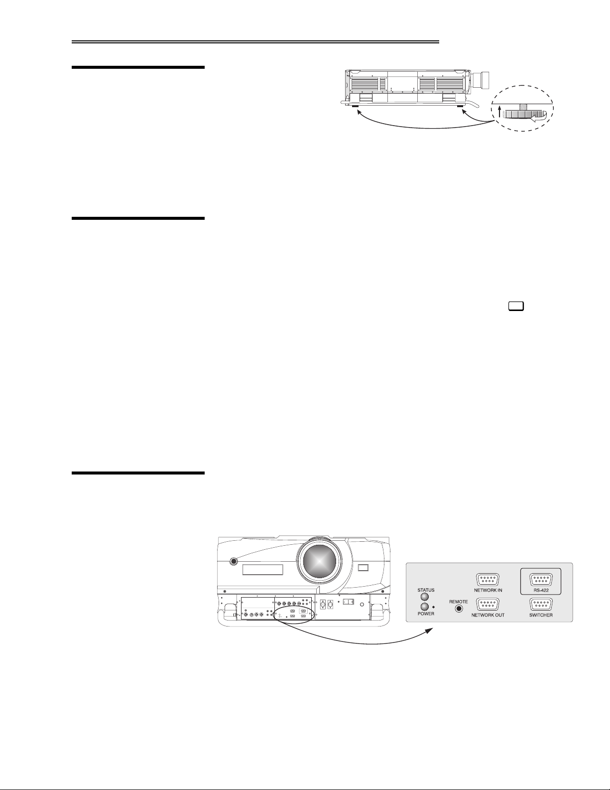
Use serial communication ports when controlling Vista
GRAPHX
10K with a
personal computer having a serial interface or when using the projector with a
Marquee switcher. Vista
GRAPHX
10K serial ports are located on the lower right
portion of the projector's front control panel as shown in Figure 2-16.
)LJXUH#50491#6HULDO#3RUW#&RQQHFWLRQV#³#560565#RU#560755
NOTES: 1) All
Vista
GRAPHX
serial connections on this panel require a 9-
10K
pin D connector. Refer to Appendix D for complete cable wiring requirements.
The "NETWORK OUT" port is provided for networking applications only —
2)
see "If using multiple projectors", below.
9LVWD
*5$3+;
8VHU*V#0DQXDO
#43.#
504:
,167$//$7,21#)#6(783
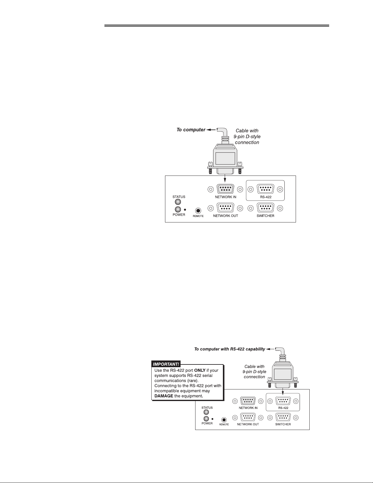
,I#XVLQJ#D#FRPSXWHU
ö
7KH#560565#3RUW
You may wish to use a computer rather than a keypad for controlling the
projector and for performing other special functions. From most computers,
connect an RS-232 serial communication cable between the computer and the
projector serial port labeled "NETWORK IN" (Figure 2-17). Then set the
projector baud rate to match that of the computer. Changing the baud rate is
described in 3.7, Adjusting and Checking System Parameters.
NOTE: In rare instances, some computers can provide
communications. See
The RS-422 Port,
below.
RS-422
serial
)LJXUH#504:1#560565#6HULDO#3RUW#&RQQHFWLRQ#WR#D#&RPSXWHU
Note: PC software is required for computer/serial control. Contact your dealer
for details.
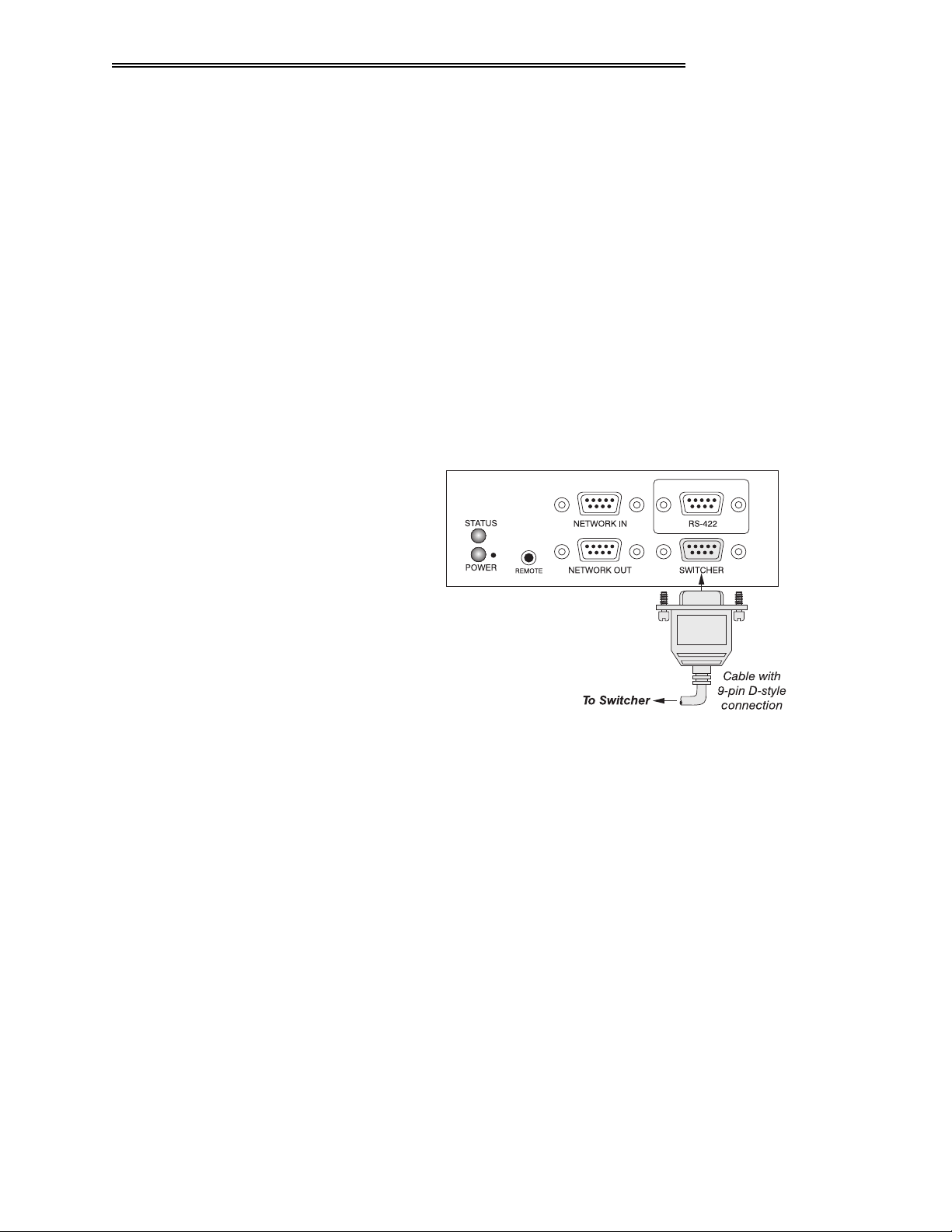
7KH#560755#3RUW
Some computers can provide
RS-422
serial communications (usually through a
plug-in adapter or external converter) rather than the RS-232 typically found on
most computers. RS-422 communication has differential transmits and receives
and is generally better suited for long distances than is RS-232 communication.
If you wish to control the projector with a computer having RS-422 capability,
connect the computer to the projector’s RS-422 port instead of the port labeled
“NETWORK IN”. Again, use RS-422 only if you are certain that your computer
has RS-422 capability (consult your documentation). See Figure 2-18.
504;
9LVWD
*5$3+;
8VHU*V#0DQXDO
#43.#
)LJXUH#504;1#560755#6HULDO#3RUW#&RQQHFWLRQ#WR#D#&RPSXWHU
,I#XVLQJ#D#VZLWFKHU
,167$//$7,21#)#6(783
,03257$17
1HYHU#XVH#WKH#560755#SRUW#XQOHVV#\RX#DUH#XVLQJ#D
FRPSXWHU#ZLWK#560755#FDSDELOLW\1#7KH#KLJKHU#YROWDJH
OHYHO#RI#WKLV#VLJQDO#FRXOG#GDPDJH#LQFRPSDWLEOH
HTXLSPHQW1
If your computer has a 6-pin XLR connector instead of a 9-pin D connector, or if
you are using the optional Vista
GRAPHX
2-Way Controller, connect to the XLR
jack on the right front panel of the projector, just under the lens.
NOTE: You cannot use two RS-422 connections simultaneously. Connect to the
9-pin D connector or the XLR jack, not both.
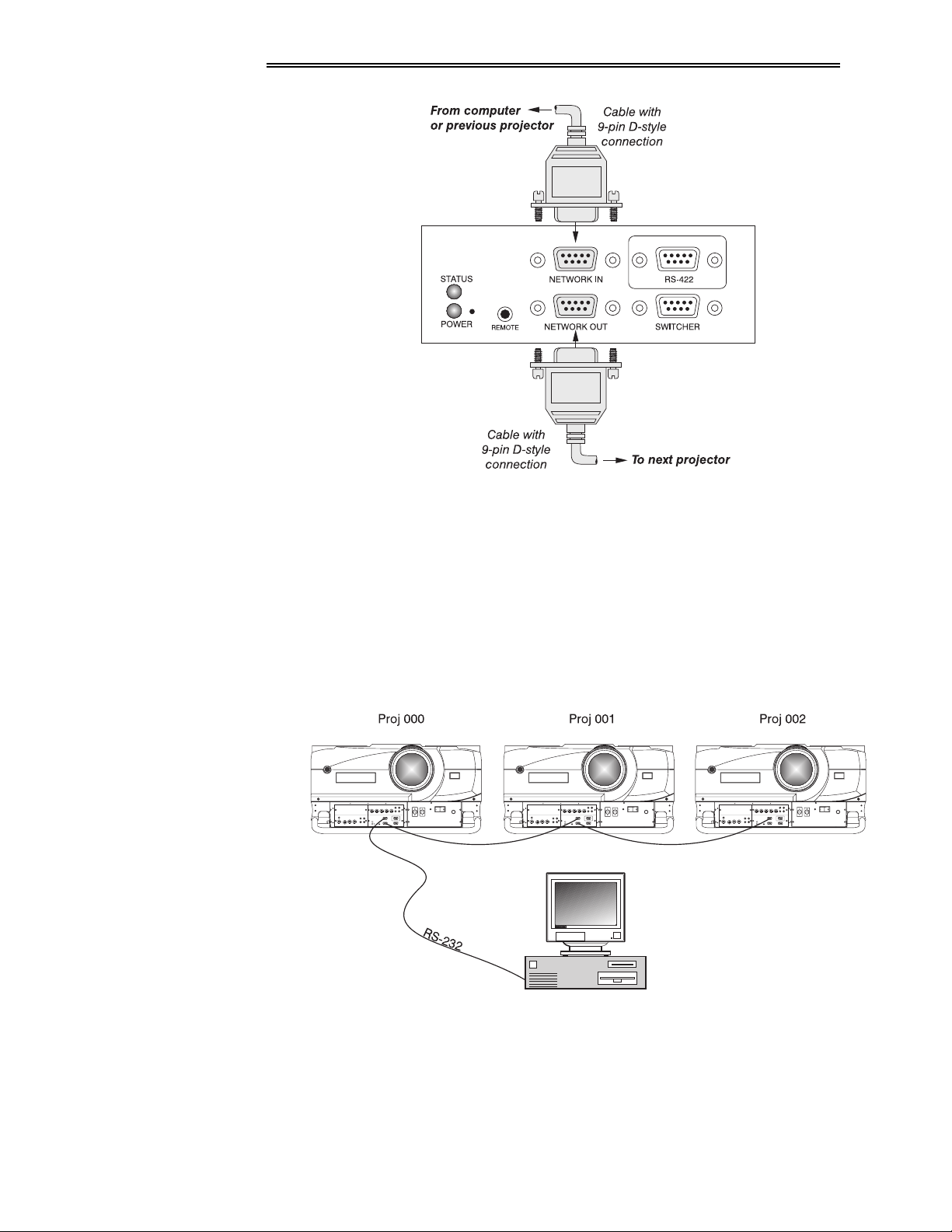
You may wish to use one or more external Marquee switchers or third-party
ö
switchers in order to significantly increase the number of sources you can use.
Connect an RS-232 serial communication cable between the switcher and the
projector serial port labeled "SWITCHER" (Figure 2-19). This port is
permanently set at 9600 baud.
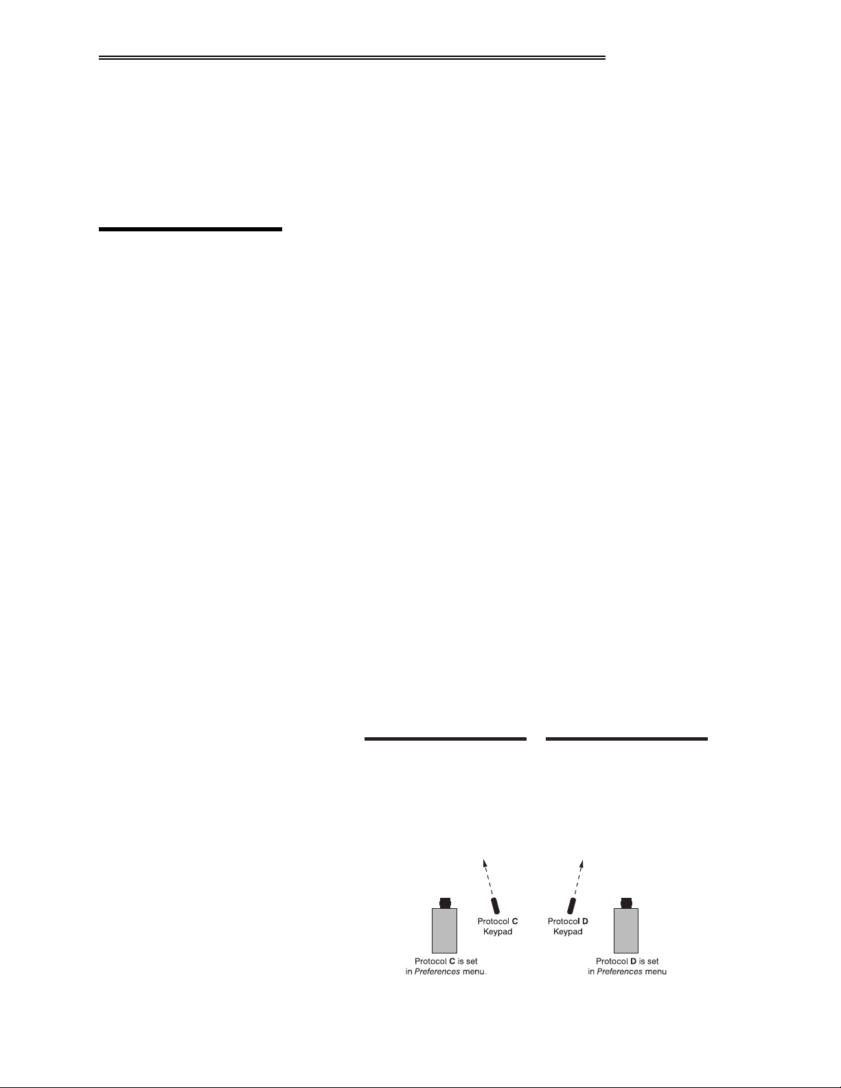
,I#XVLQJ#PXOWLSOH
#SURMHFWRUV
)LJXUH#504<1#560565#6HULDO#3RUW#&RQQHFWLRQ#WR#D#6ZLWFKHU
To control multiple projectors with a computer/controller, chain the projectors
ö
together by connecting the "NETWORK OUT" connector of the first projector
(already connected to the computer/controller) to the "NETWORK IN"
connector of the next projector in the chain (Figure 2-20).
9LVWD
*5$3+;
8VHU*V#0DQXDO
#43.#
504<
,167$//$7,21#)#6(783
)LJXUH#50531#$GGLQJ#$QRWKHU#3URMHFWRU
Continue connecting projectors in this way to the last projector in the chain, so
that only the last projector has an empty "NETWORK OUT" connector. See
Figure 2-21.
Communication parameters such as baud rate must be set to match the particular
controlling device—refer to the documentation that came with the controlling
device in order to determine the proper baud rate. See 3.7, Adjusting and Checking
System Parameters if you need help changing the projector baud rate from its default of
9600.
5053
9LVWD
*5$3+;
8VHU*V#0DQXDO
#43.#
)LJXUH#50541#7KUHH#1HWZRUNHG#RU#%&KDLQHG%#3URMHFWRUV
Notes: 1) To avoid damage, connect only properly wired RS-232 serial
communication cables. See Appendix D for details. 2) It is recommended that
each communication cable be no more than 25 feet in length.
3URMHFWRU#1XPEHU
,167$//$7,21#)#6(783
Each projector can be assigned a unique 3-digit projector number (for example,
ö
001). These numbers are particularly useful when you are working with multiple
linked projectors, enabling you to direct commands to a certain projector rather
than broadcast to all projectors. For complete information on how to assign
projector numbers, see 3.7, Adjusting and Checking System Parameters.
5143 .H\SDG
3URWRFROV
At manufacture every keypad is assigned a default protocol, which is simply a
collection of settings that determine how the keypad operates. Once assigned,
this protocol remains in effect until it is changed — that is, the keypad will
operate as it currently does until you change its protocol.
Protocols are most useful for multiple-projector applications. For example, you
might want to change a keypad protocol if you are working with two projectors
and two remote keypads in the same room and need to control each projector
independently (Figure 2-22). When Keypad A has a different protocol than
Keypad B, each keypad communicates only with the projector having a matching
protocol. Or, if you have a network of two or more projectors connected together
via RS-232 serial ports, you may want only certain projectors to respond to a
wired keypad.
NOTE: Matching the protocol on the projector to that of a keypad is done
through a setting in the Vista
and Checking System Parameters
GRAPHX
10K Preferences menu. See
3.7, Adjusting
for further information on how to change the
projector's infrared sensor (rear and front) protocol.
A protocol for either type of remote keypad — IR or wired — can be changed
through software commands entered on the keypad. A new protocol set through
software commands remains in effect until the keypad batteries are removed and
replaced (if an IR remote), or until the keypad is unplugged (if a wired remote).
A remote can also be changed manually —you can "hard-wire" new jumper
settings inside the keypad so that they remain in effect until you change the hardwiring. Note that a hard-wired protocol can be temporarily overridden by the
software protocol change, effective until the keypad is unplugged and plugged in
again (if a wired remote) or until a battery is removed (if an IR remote).
)LJXUH#50551#,QGHSHQGHQW#.H\SDGV#DQG#3URMHFWRUV
9LVWD
*5$3+;
8VHU*V#0DQXDO
#43.#
5054
,167$//$7,21#)#6(783
5HPRWH#.H\SDG
3URWRFRO
³#,5#25#:,5('#.(<3$'#³
The standard IR remote keypad or the optional wired remote can be set to one of
ö
two different protocols — “C” or “D”. To hard-wire a protocol to “C” or “D” in
either remote, follow Steps 1 through 5:
6WHS#4
Unplug the keypad from the projector (applies to wired remote only).
6WHS#5
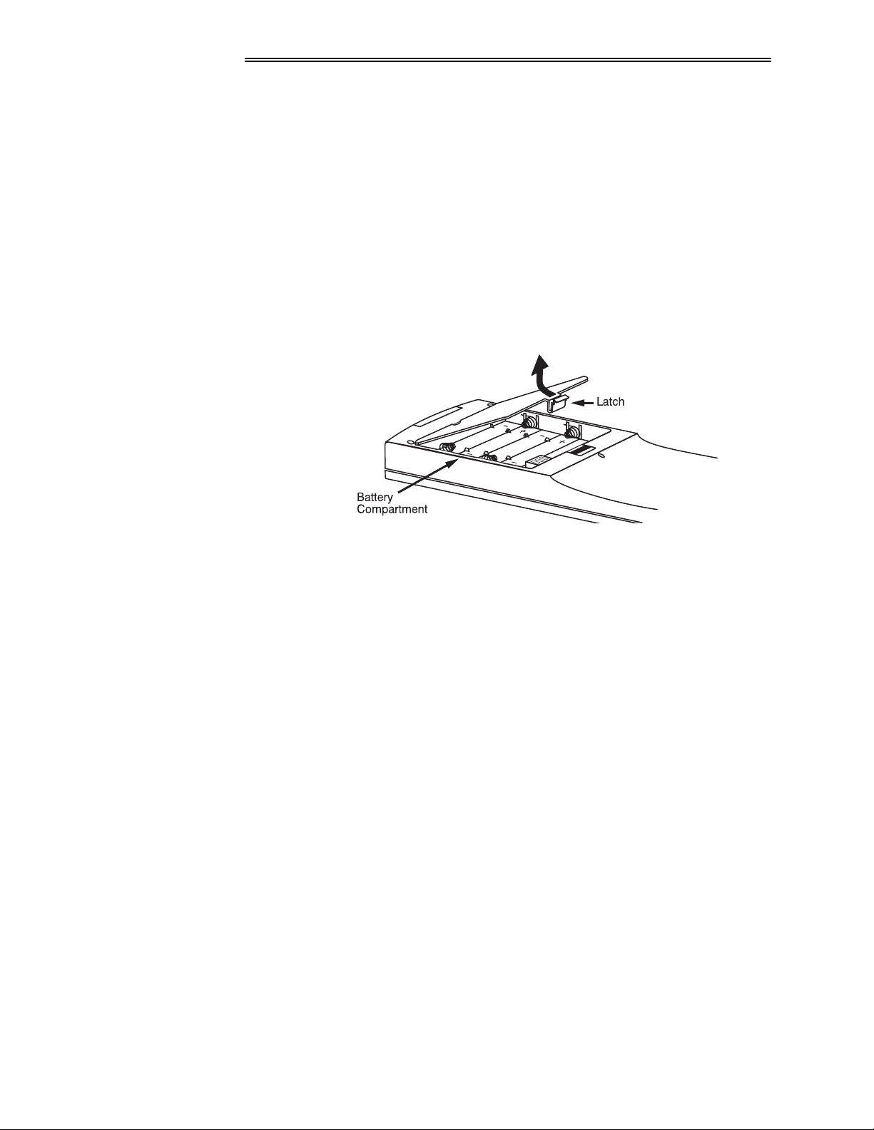
Unlatch and open the empty battery compartment on the back of the keypad as
shown in Figure 2-23.
NOTE: A wired keypad will open as shown, but there will be a cable passing
through the battery compartment cover.
)LJXUH#50561#2SHQLQJ#WKH#.H\SDG
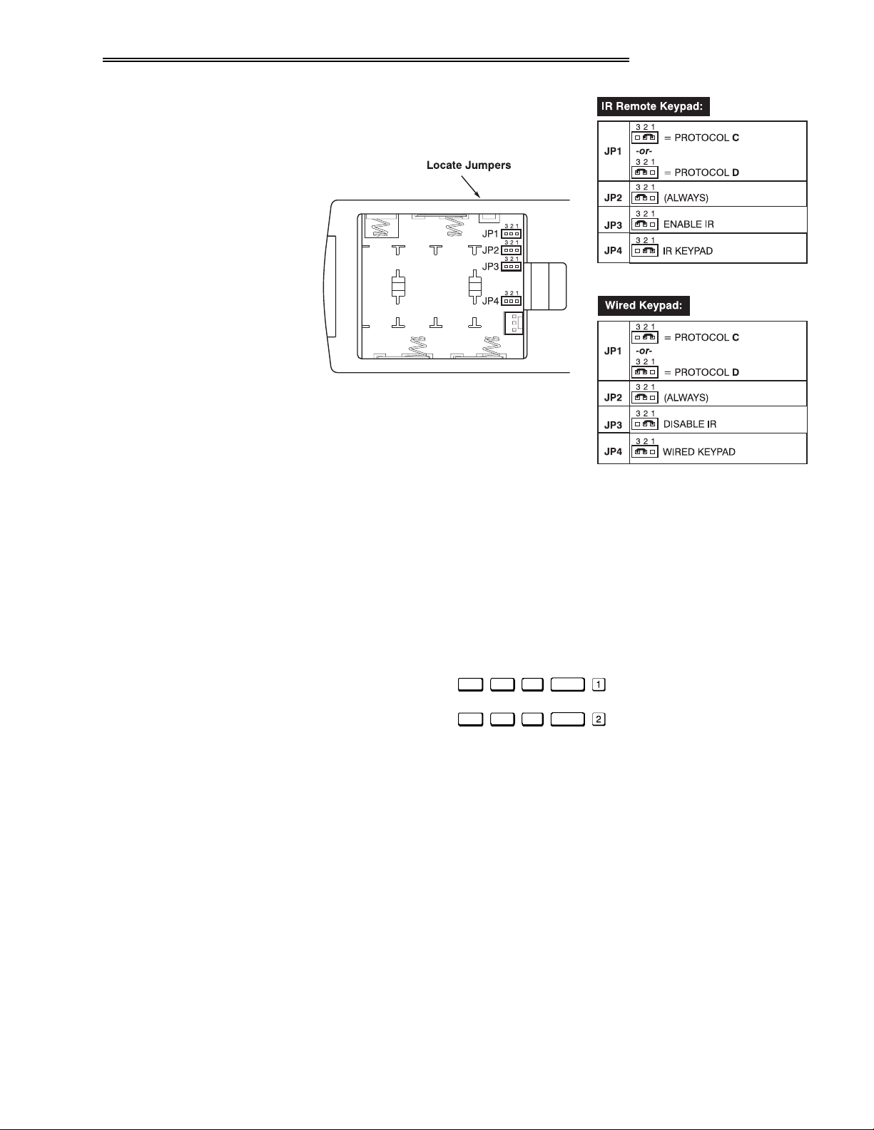
6WHS#6
Find the 4 jumpers located along the latching side of the battery compartment.
These jumpers set the keypad protocol and other settings so that the keypad
functions in a certain manner.
6WHS#7=#6HW#WKH#-XPSHUV
Set the jumpers as shown in Figure 2-24. Take care to refer to the correct part of
the drawing — IR or wired (optional). Use tweezers or needle-nose pliers to
remove and replace each jumper as necessary.
•
jumper: For either remote, set between pins 1 and 2 to set as Protocol
#
-4
“C”. Set between pins 2 and 3 to set as Protocol “D”.
•
jumper: For either remote, set between pins 2 and 3 as shown; otherwise,
#
-5
the projector will not respond correctly to keypad commands.
•
jumper: For the IR remote, make sure that the jumper is set between pins
#
-6
2 and 3 as shown. For the wired remote, make sure that the jumper is set
between pins 1 and 2 as shown.
•
jumper: For the IR remote, make sure that the jumper is set between pins
#
-7
1 and 2 as shown. For the wired remote, make sure that the jumper is set
between pins 2 and 3 as shown.
5055
9LVWD
*5$3+;
8VHU*V#0DQXDO
#43.#
6WHS#8
Replace battery compartment cover. Plug into projector (wired keypad only) and
test.
,167$//$7,21#)#6(783
)LJXUH#50571#/RFDWLQJ#DQG#6HWWLQJ#WKH#-XPSHUV
NOTE: Although they are similar, a Vista
GRAPHX
10K wired keypad cannot be
converted into an IR remote keypad, nor vise versa.
6+257&87#0(7+2'=
You can also issue software protocol settings through the keypad. These
software commands will be lost when the keypad is either unplugged or when a
battery is removed — the keypad will revert back to the hard-wired jumper
settings (see above) until you enter the software commands again.
Press
Press
,QSXW4 &RORU 3L[HO
,QSXW4 &RORU 3L[HO
3RVL WLRQ
3RVL WLRQ
= Protocol “&”
= Protocol “'”
NOTE: If you change any keypad to a new protocol and the projector stops
responding, the projector may be set to a conflicting protocol. Use the
projector's built-in keypad to access the
Preferences
menu. Under “Front IR
Keypad” or “Back IR Keypad” or "Wired Keypad", select the protocol that
matches the new protocol of the keypad at hand. The projector should now
respond properly.
9LVWD
*5$3+;
8VHU*V#0DQXDO
#43.#
5056


6HFWLRQ#6
2SHUDWLRQ
614 2YHUYLHZ
615 3URMHFWRU#%DVLFV
This section explains how to use the Vista
GRAPHX
10K projector once it has been
installed. Please read through these pages before using the projector for the first
time. An understanding of Vista
GRAPHX
10K features and how to access them
will help you to take full advantage of the capabilities of the projector within
minutes. Organization of this section is as follows:
614 2YHUYLHZ111111111111111111111111111111111111111111111111111111111111111111 SJ1#604
615 3URMHFWRU#%DVLFV 111111111111111111111111111111111111111111111111111111 SJ1#604
616 8VLQJ#WKH#.H\SDG1111111111111111111111111111111111111111111111111111 SJ1#608
617 1DYLJDWLQJ#WKH#0HQXV 1111111111111111111111111111111111111111111 SJ1#6045
618 8VLQJ#,QSXWV#DQG#&KDQQHOV11111111111111111111111111111111111 SJ1#604:
619 $GMXVWLQJ#WKH#,PDJH 1111111111111111111111111111111111111111111111 SJ1#6054
61: $GMXVWLQJ#DQG#&KHFNLQJ#6\VWHP#3DUDPHWHUV 1111111 SJ1#6066
61; 8VLQJ#0XOWLSOH#3URMHFWRUV 11111111111111111111111111111111111111 SJ1#606<
61< (UURU#&RQGLWLRQV1111111111111111111111111111111111111111111111111111 SJ1#6073
NOTE: Installation involves locating the projector and adjusting it for use at
that location. If you have not yet installed the projector, refer to
Installation and Setup
Most Vista
GRAPHX
.
10K functions and adjustments are entered through keypad
Section 2,
commands that either control the projector directly or activate a system of
intuitive menus. Variations in settings can be defined and retained in the
projector's internal memory as a custom channel, with up to 99 different
channels possible. Focus, lens offset, shutter, and (with applicable ILS
®
lenses)
motorized zoom can also be controlled and recalled from a remote location.
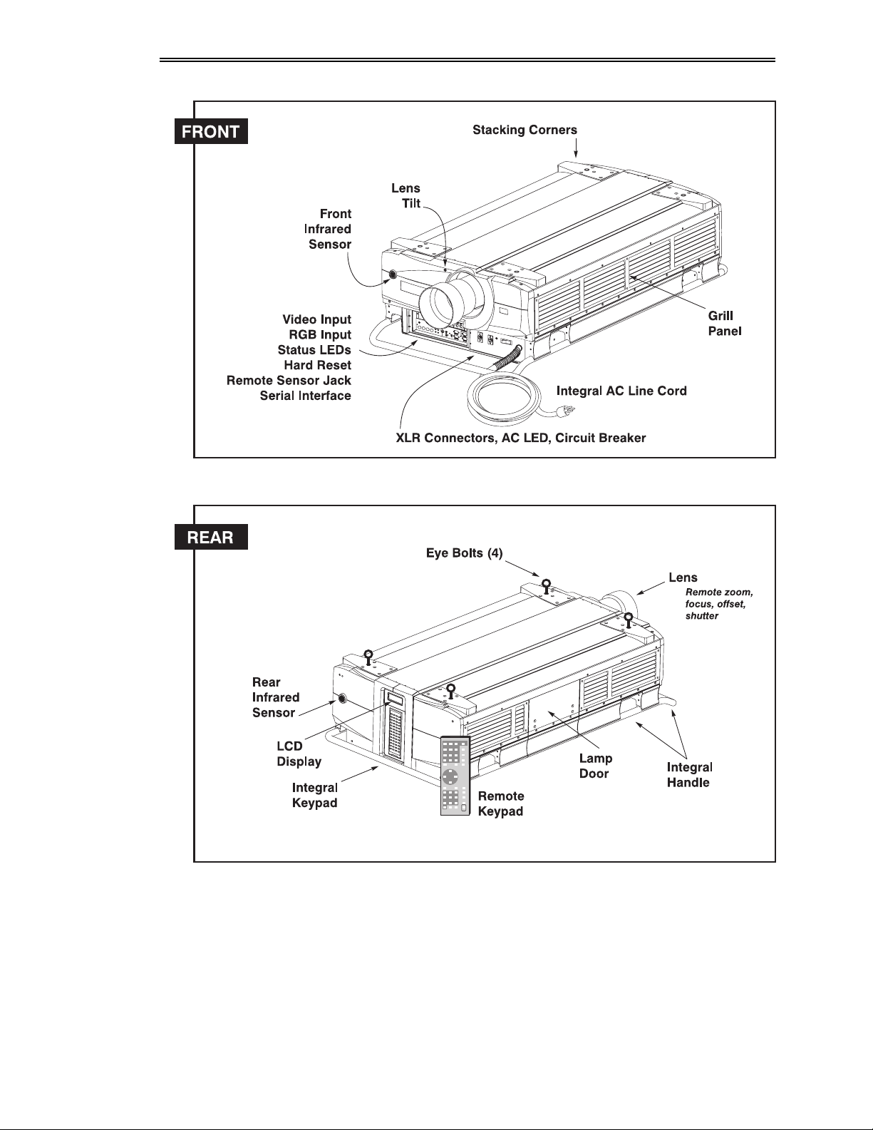
Main projector components are shown on the following page.
9LVWD
*5$3+;
8VHU*V#0DQXDO#
#43.#
604
23(5$7,21
&RPSRQHQWV
+6HH#)LJXUHV#604#DQG#605,
9LVWD
605
*5$3+;
8VHU*V#0DQXDO
#43.#
)LJXUH#6041#
5(027(#&21752/#=220##0
ö
Vista
GRAPHX ILS
Vista
®
zoom lens (optional) rotates to adjust the size of the image at
Accessed through the keypad, the lens barrel of a
10K,
#3URMHFWRU#&RPSRQHQWV
GRAPHX
the current throw distance (projector-to-screen distance). Minimum and
maximum image sizes depend on which zoom lens is installed — see Section 5,
Specifications. To adjust zoom manually, remove the zoom adapter collar (see
Section 4, Maintenance).
23(5$7,21
5(027(#&21752/#)2&86#0
Accessed through the keypad, focus adjusts the
sharpness of the image at the current throw distance.
5(027(#&21752/#/(16#2))6(7#0
Accessed through the keypad, horizontal and
vertical offsets shift the lens to move the image. See Section 2, Installation and
Setup for the offset ranges for any given lens.
/(16#7,/7#$'-8670(17#0
Accessed through the front bezel of the projector, this
adjustment allows the lens to be tilted slightly in its mount.
5(027(#&21752/#6+877(5#0
Closing the shutter closes the lens and blocks the
image. The shutter is controlled through the keypad.
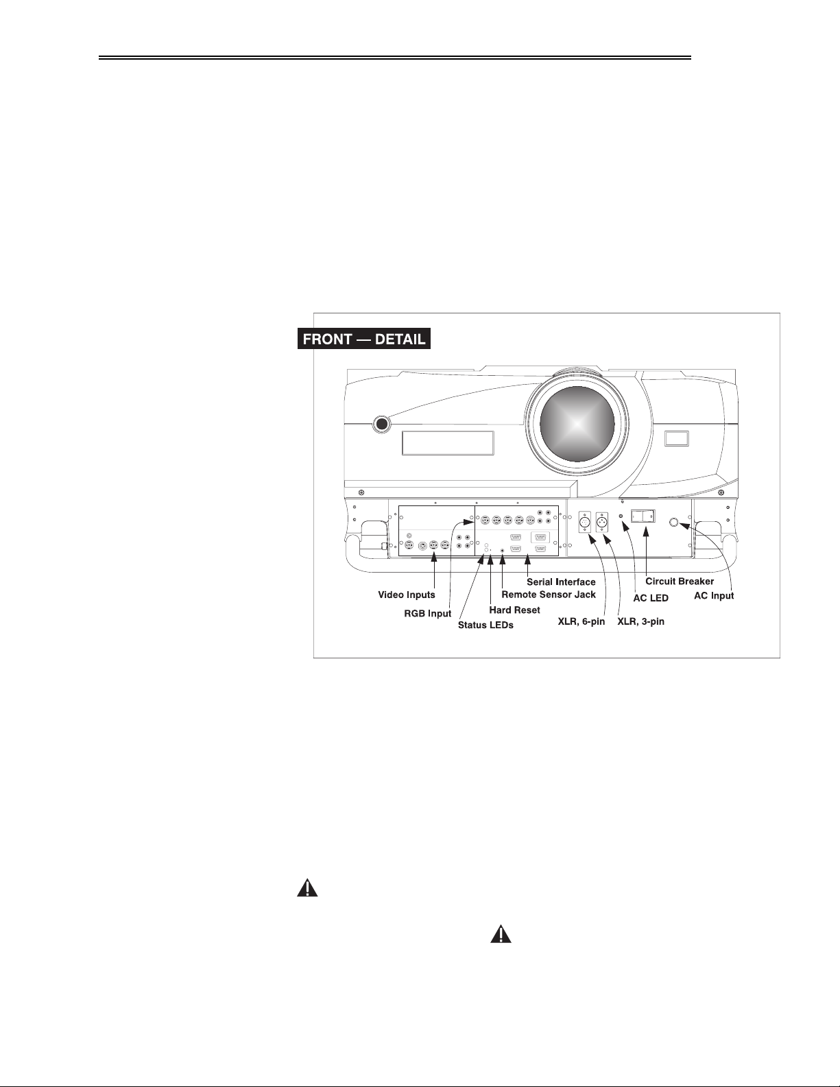
)LJXUH#6051#'HWDLO#RI#)URQW#3DQHO
&20326,7(2609,'(2#,1387#0
Accepts a composite video and S-Video signal from
devices such as VCRs.
5*%#,1387#0#
6(5,$/#,17(5)$&(#+:,7+#/223#7+528*+,#0
Accepts RGB and sync signals from devices such as computers.
Allows one or more projectors to be
remotely controlled by a computer or controller, and provides a communications
connection for Marquee and third-party (e.g., Extron) signal switchers.
Integral 30 amp AC line cord. The projector requires
$&#/,1(#&25'#,1387#
#
0
AC power of 220 to 240 VAC, 50 to 60 Hz @ 12 amps.
#
:$51,1*=
#
#'R#QRW#DWWHPSW#RSHUDWLRQ#LI#WKH#$&#VXSSO\#LV#QRW
ZLWKLQ#WKH#VSHFLILHG#YROWDJH#DQG#SRZHU#UDQJH1
9LVWD
*5$3+;
#;3343.
HU*V#0DQXDO
606

23(5$7,21
67$786#/('6#0
Two LEDs (light emitting diodes) located to the right of the
Video Input Panel indicate "Status" (top) and "Power" (bottom). During normal
operation, the "Power" light is steady green and the "Status" light flashes green
each time a key is pressed or when the projector receives a serial command. Use
the following as a guide:
NOTE: A steady red power light accompanied by a coded pattern of red and
yellow flashes from the status light indicates an internal system error. Consult
the rear LCD display for an explanation. Should the problem persist, contact a
qualified service technician through your dealer or at Electrohome.
Indicates whether or not the projector is receiving proper AC current
$&#/('#0
(20 amps maximum). This LED should be
(green) whenever the projector is
2Q
plugged in. If it goes off during operation, this indicates that the projector
received more than 20 amps of current and that the projector’s circuit breaker
triggered an automatic shutdown of the projector.
Standard keypad for tethered remote control of the projector.
5(027(#.(<3$'#0
,17(*5$/#.(<3$'#0
/&'#',63/$<#0
,1)5$5('#6(16256##0
GRAPHX
Vista
#
Alternative location for entering commands.
Feedback for monitoring projector activities and status.
The infrared (IR) sensors on the front and rear of
10K receive infrared signals from the IR keypad for remote control
of the projector. For proper operation make sure that these sensors are not
blocked.
5(027(#6(1625#-$&.#0#
For adding another IR sensor.
607
9LVWD
*5$3+;
8VHU*V#0DQXDO
#43.#
6$)(7<#&,5&8,7#%5($.(5#0
#
"Detects faulty or excessive AC and
automatically shuts down the projector to prevent damage. During normal
operation, the rocker switch should be in the
position and the adjacent LED
2Q

23(5$7,21
will be green. If it moves to the
restart by first moving the breaker back to the
as usual. If the breaker continues to “trip” (moving to
position, the projector will power off —
2II
position, then try powering up
2Q
), the projector will
2II
remain inoperable until the AC problem is corrected. Never use the circuit
breaker as an
;/5#&211(&7256#0
switch.
2Q22II
"3-pin and 6-pin. For connecting the optional wired remote
keypad (3-pin) or optional Two-Way controller (6-pin).
+$5'#5(6(7##0
"Emergency access for powering down the projector in the event
of a system failure. Insert pen point or small screwdriver.
,17(*5$/#+$1'/(##0
"For hoisting (side handles only) or hand transport of the
projector.
67$&.,1*#68332576##0
"For secure stacking of projectors on the floor (maximum
of three high).
:$51,1*
6WDFN#)/225002817#SURMHFWRUV#RQO\1
(<(#%2/76#0
"For safe hoisting / installation of the projector. Attach with at least
20 in. lb. torque.
/$03#'225##0
"For accessing the lamphouse assembly, such as for replacement.
616 8VLQJ#WKH
.H\SDG
,17$.(#*5,//#0
The Vista
"Louvered area for air intake. Remove to replace 2 air filters.
GRAPHX keypad appears in three locations:
•
Built-in
•
Infrared (IR) Remote
•
Wired Remote
to the rear of the projector
for tetherless control
(optional) tethered to the front of the projector
While each keypad is identical in layout and provides complete control of the
projector, you may find one keypad more convenient than another for your
specific installation and application.
NOTE: For extra long distances and/or harsh environments, you may prefer to
use an optional remote Vista
For operating details, please see the
GRAPHX 2-way Controller to control the projector.
2-Way Controller User’s Manual
included
with the controller.
9LVWD
*5$3+;
#;3343.
HU*V#0DQXDO
608

23(5$7,21
609
,5#5HPRWH
:LUHG#5HPRWH
³237,21$/³
9LVWD
*5$3+;
%XLOW0LQ
8VHU*V#0DQXDO
#43.#
)LJXUH#6061#.H\SDG
This keypad is located at the rear of the projector. An LCD window above this
ö
keypad provides feedback regarding current status and activities of the projector.
The IR Remote Keypad controls the projector by way of wireless
ö
communications from a battery-powered infrared (IR) transmitter. Use the IR
remote keypad the same way you would use a remote keypad supplied with a TV
or VCR. When making key presses, point the keypad either toward the screen or
toward the front or rear of the projector. One of two sensors on the projector will
detect the signals and relay the commands for internal processing.
The wired remote keypad connects to the front 3-pin XLR jack via a 50 ft.
ö
extension cable. It is recommended when:

*XLGH#WR#.H\SDGV
23(5$7,21
• the rear of the projector is inaccessible
• the lighting conditions are unsuitable for proper IR transmission
• you want to use a separate keypad for each projector in a group
Keep in mind the following guidelines:
ö
4,
Press keys one-at-a-time; there are no simultaneous key presses required.
5,
For any key having an “*” (
3RZH U-
, for example), hold the key for a second or
two in order to toggle the function with a single key press. For other keys (or
to use a “*” key in conjunction with
21
or
2))
), a momentary press
similar to a mouse click is sufficient.
6,
Press the “lightbulb key” for approximately one second to temporarily
illuminate the backlight for the keys without sending any other command.
7,
,
21
, and
,
2))
repeat their “arrow” actions when held down. For
other keys, release and press again to repeat an action.
8,
If you press a key while the projector is busy with another action, such as
during a power-up, the key press may not take effect.
When you turn on the projector it begins operating at presentation level, such as
an image from the most recently used source signal. The projector temporarily
leaves presentation level whenever you use the keypad to work with control
settings, display menus, or on-line help. For example, pressing
0HQX
after startup
displays the main menu — presentation level is no longer active, although the
image continues to be displayed in the background. Press
0HQX
again (or
return to presentation level.
([LW
) to
.H\SDG#&RPPDQGV
3RZH U-
,QSXW4
#
,QSXW5
,QSXW6
#
Specific keypad commands are explained below:
ö
3RZHU#2122))
Press and hold for a second or two to turn the projector on or off with a single
key press. Or press
3RZH U-
followed immediately by
21
or
2))
if you want to
guarantee the correct toggle (useful if you are unsure of the present status).
NOTES: 1) Whenever the projector is turned off, the lamp cooling fans remain
on for about five minutes to cool the lamp sufficiently
projector unless the lamp cooling fans have shut off. 2)
. Do not unplug the
It is a good idea to
avoid turning a projector back on until it has been off for at least five minutes.
Hot re-strikes of the lamp may reduce lamp life.
##
,QSXW#4
,QSXW4
Press
This is the same as entering
to select the input connected to
,QSXW
.
,1387#4#
on the projector (data input).
,QSXW#5
,QSXW5
Press
interface). This is the same as entering
to select the input connected to
,QSXW
,1387#5#
on the projector (an optional
.
,QSXW#6
,QSXW6
Press
video). This is the same as entering
to select the input connected to
,QSXW
,1387#6#
.
on the projector (composite
9LVWD
*5$3+;
#;3343.
HU*V#0DQXDO
60:

23(5$7,21
#
,QSXW7
,QSXW#7
,QSXW7
Press
to select the input connected to
This is the same as entering
,QSXW
,QSXW
,QSXW
Press
,1387#7
,QSXW
.
when you want to display from a specific source location, such
on the projector (S-Video).
as a switcher connected serially to the projector’s switcher port. The first digit
represents the switcher number (usually 1-9, or “0” for one of the four inputs on
the projector), the second digit represents the slot number (1-9). For example:
,QSXW
= display data from switcher 1, slot 2.
NOTES: 1) Although you don’t need to use the input key unless a switcher is
connected to the projector, you can also use
on the projector itself: use
switcher), then
, , , or
as the first digit (representing the projector as the
as the second digit (the desired input slot
,QSXW
to access the four input “slots”
number). in combination with higher numbers is an invalid entry. 2) See
Using Channels and Inputs
&KDQ
&KDQQHO
&KDQ
Press
to select a channel representing a specific source setup defined and
for a detailed explanation of inputs.
stored in projector memory. Once you enter a channel number, the display will
automatically update according to the setup parameters defined for that channel.
NOTE: Precise
(from within the
&KDQ
key behavior depends on which
Preferences
menu) you have chosen for the
Channel Selection
&KDQ
key. For
example, you can choose to see a scrollable list of channels when you press
or you may prefer to enter a one- or two-digit number channel number. To set up
&KDQ
6WE\-
the
###
6WDQGE\
Press
key, see
6WE\-
Preferences
and hold for a second or two to blank the display and mute the audio
later in this section.
output while keeping the projector in a warmed-up and ready state. Or quickly
press and release
6WE\-
and follow immediately by
21
or
2))
if you want to
guarantee the correct toggle (useful if you are unsure of the present status). Note
that all electronics remain ON in standby mode, even though lamp power
reduces to a minimum and the image turns to black. To leave standby press and
hold
6WE\-
again (or use
6WE\-
2))
). Or simply press
([LW
.
3.5,
option
&KDQ
,
60;
9LVWD
*5$3+;
8VHU*V#0DQXDO
#43.#
#
#
#
0HQX
##
0HQX
0HQX
Press
to display the main menu. A list of seven numbered options and icons
appears for access to specific functions, such as Channel List or Size / Position.
(QWHU
Press
(QWHU
Press
0HQX
again (or
(QWHU
to select a highlighted item, toggle a checkbox (checked vs.
([LW
) to return to presentation level.
unchecked), finish with a double slidebar, or accept a parameter adjustment and
return to the previous menu or image.
([LW
([LW
Press
([LW
to save most parameter adjustments and return to presentation level.

23(5$7,21
21
2))
NOTE:
([LW
does
save changes within text editing boxes or pull-down lists.
not
$UURZ#.H\V
Use the
21
or
2))
keys to navigate within a menu or pull-down list or to
increase or decrease the value in the second (bottom) slidebar of a double
slidebar. Use
or
for continuous scrolling. Also use
to change all other slidebar values — hold as desired
or to jump between “pages” in a
long pull-down list.
21
or
2))
#
Use
21
or
2))
in conjunction with certain toggle keys—those labeled with an
asterisk—to ensure a toggle only in the desired direction. When turning the
projector on, for instance, you may be too far from the projector to know
whether it is really off or if the shutter is just closed. If you press
3RZH U-
and
simply hold it for a second or two in hopes of turning the projector on, the
projector will turn off if the projector is actually already on. Instead, to avoid the
risk of toggling in the wrong direction, quickly press and release the function
key you wish to toggle (in this case
press either
21
or
2))
as desired. The specific toggle will occur.
3RZH U-
). Then immediately (within 2 seconds)
Toggle keys are labeled with an asterisk on the keypad. They are listed below:
•
•
•
•
•
6KXWWHU-
6KXWWHU-
6WE\-
6WE\-
3RZH U-
3RZH U-
0XWH-
0XWH-
26'-
26'-
21
+
+
= close the shutter (dowser)
2))
= open the shutter (dowser)
+ 21 = put the projector in standby mode
2))
+
+
+
= leave standby
21
= turn the projector on
2))
= turn the projector off
+ 21 = turn the audio on
2))
+
+
+
= turn the audio off
21
= turn the menu system on
2))
= turn the menu system off
&RORU
&RORU
&RORU
Press
to adjust the color saturation level, or the amount of color in a video
image. Lower settings produce less saturated colors — a setting of “0” produces
a black and white image, for example. If the color level is too high, colors will be
overpowering and unrealistic. Use
and until the desired color
saturation level is displayed.
7LQW
7LQW
Press
7LQW
to adjust the red/green color hue for true color reproduction of NTSC
video signals. For best results, adjust tint while displaying a proper test pattern
— otherwise, it is recommended that tint remain at its default setting. Use
and until the desired tint is displayed.
'HWDLO
'HWDLO
'HWDLO
Press
to adjust the sharpness of a video image. Use and until the
display is as sharp as desired, keeping in mind that any level of detail above 50%
9LVWD
*5$3+;
#;3343.
HU*V#0DQXDO
60<

23(5$7,21
will also introduce some level of noise in the image. Set below 50% to filter the
signal and remove noise from a noisy source.
&RQW
&RQWUDVW
&RQW
Press
your image. Use
to increase or decrease the difference between light and dark areas of
and until you reach the desired level of contrast,
making sure that the whites remain bright but not distorted or tinted.
%ULJKW
%ULJKWQHVV
%ULJKW
Press
that black just changes to very dark gray. Use
to increase or decrease the amount of perceived light in the image so
and until you reach the
desired level. See 3.6, Adjusting the Image (Image Settings subsection).
9RO
9ROXPH
Press
9RO
to control the audio level. Use and until you reach the
desired volume.
3URM
###
3URMHFWRU
3URM
Press
to display an editable box indicating which projector is currently
listening to the keypad. The number that
appears will match what has been defined in
the Preferences menu.
3L[HO
3RVL WLRQ
To use a certain projector, enter the 3-digit
number assigned to the projector you want to use, or use
(QWHU
Press
to select. Press
To broadcast to multiple projectors, press
([LW
to cancel.
3URM
and then
and to scroll.
)XQF
without
entering a
projector number. Keypad commands will then affect all projectors present.
NOTES: 1) The "Broadcast Keys" option in the Preferences menu must be
selected for only
OFF (disabled) for the remaining projectors. See
projector in a serial network. The keypad in use must be
one
2.10. Keypad Protocols
, and
3.7, Adjusting and Checking System Parameters.
3L[HO
3L[HO
Press
to access the pixel tracking and pixel phase double slidebar. Use
and to increase or decrease the frequency of the pixel sampling clock to
correct the proportion of the image. Use
21
and
2))
to increase or decrease
pixel phase so that any shimmer disappears and the image is stable throughout.
See 3.6, Adjusting the Image (Image Size / Position subsection).
3RVLWLRQ
3RVL WLRQ
Press
Use
to move the image up, down, right, or left using the double slidebar.
and to move the image left or right, use
21
and
2))
to move the
image up or down.
6043
9LVWD
*5$3+;
8VHU*V#0DQXDO
#43.#
/HQV
/HQV
/HQV
Press
to access the 2 double slidebars focus/zoom and horizontal/vertical
lens offset in the Lens menu. Use
21
and
2))
to adjust the image sharpness or

23(5$7,21
to shift the image up or down. Use and to zoom in and out (requires
zoom lens) or to shift the image slightly left or right. Note zoom range is 3-97.
6KXWWHU-
0XWH-
#
)XQF
6KXWWHU
Press and hold
6KXWWHU-
for a second or two to toggle the mechanical lens shutter
(dowser) closed or open with a single key press. Or quickly press and release
6KXWWHU-
and follow immediately with
21
or
2))
if you want to guarantee the
correct toggle (useful if you are unsure of the present status). Close the shutter
whenever you want to mute all display yet maintain access to all projector
functions. Open the shutter to regain the display.
NOTES: 1) Like standby, closing the shutter automatically reduces internal light
to a minimum so that heat doesn’t build up inside the projector. 2) The status of
the shutter is shown in the LCD window on the rear panel of the projector.
0XWH
Press and hold
single key press. Or quickly press and release
21
or
0XWH-
for a second or two to toggle the audio on or off with a
0XWH-
and follow immediately with
2))
if you want to guarantee the correct toggle (useful if you are unsure
of the present status).
)XQFWLRQ#.H\
)XQF
)XQF
followed by a 2-digit number to access any of
)XQF
will display a 128-
will display a scrollable list. A list of test
From presentation level, press
the projector’s resident test patterns. For example,
step grayscale pattern, or
common pattern codes appears on the back of the IR remote keypad and in the
Service subsection later in this manual.
You can also use
)XQF
followed by a special 2-digit number to directly access
certain options in the Size / Position or Image Settings menus — this will enable
a second method for adjusting the option immediately, without going through the
menu system. For example, to toggle the VCR option: press
ILS adjustment immediately: press
)XQF
.
To broadcast to all projectors in a network, press
NOTES: 1) Once
)XQF
is pressed in presentation level, the projector will not
)XQF
)XQF
.
respond to non-numeric entry until 2 digits have been entered or until 5 seconds
of inactivity have elapsed. 2) Certain engineering codes will freeze an image or
display an unfamiliar menu or image. Should you accidentally select one of
these special codes after pressing
)XQF
, press
([LW
to cancel the function and
return to presentation level.
26'-
26'#+2Q0VFUHHQ#GLVSOD\,
#
Press and hold
off (i.e., visible or invisible). Or press
2))
to guarantee the correct toggle direction (useful if you are unsure of the
26'-
for a second or two to toggle menus and test patterns on or
26'-
followed immediately by 21 or
present status). Note that invisible menus are fully functional.
; to stop an
9LVWD
*5$3+;
#;3343.
HU*V#0DQXDO
6044

23(5$7,21
NOTES: 1) With OSD on, you can still mute menus, error messages, slidebars,
etc. with the appropriate setting in the Preferences menu. 2) The status of the
26'-
key is displayed in the LCD window on the rear panel of the projector.
+HOS
+HOS
#
+HOS
Press
+HOS
for detailed information about any current menu and highlight. Press
again to exit. From presentation level, press
+HOS
to access the General Help
menu consisting of Using Help, Projector Setup, Keypad, Channel Selection and
Status LEDs. Press
7HV W
7HVW
#
7HV W
Press
to display one of five selected test patterns. Press
the next pattern in this sequence, and so on.
or press
([LW
at any time to remove the current test pattern from the screen.
([LW
to leave General Help and return to presentation level.
7HV W
again to display
7HV W
will exit after the fifth pattern,
NOTE: For a complete list of all test patterns, including those accessed through
)XQF
the
key, see
Service
later in this section.
.H\SDG#RSHUDWLQJ#VHWWLQJV#+SURWRFROV,
The remote keypad and the optional wired keypad both store keypad operating
settings (called protocols) in memory. In some advanced applications, such as
when you want to use two separate keypads to control two projectors
independently, you may want to override the original protocol (called "C") set at
manufacture for one of the keypads. See section 2.10, Keypad Protocols for
complete instructions on changing protocol.
617# 1DYLJDWLQJ
WKH#0HQXV
Most of the controls for the projector are accessed from within the Vista
GRAPHX
10K menu system. There are seven groups of related functions in all, with each
0HQX
group selectable from the main menu as shown in Figure 3-4. Press
at any
time to display the Main menu list. The menu icons for Size / Position, Image
Settings, Channel List, Communications, Preferences, Status (primarily readonly), and Service (password protected) appear in a numbered list:
6045
9LVWD
*5$3+;
8VHU*V#0DQXDO
#43.#

)LJXUH#6071#0DLQ#0HQX
23(5$7,21
2Q0OLQH#+HOS
On the keypad, either enter the number corresponding to the function menu you
wish to access, such as
highlight the desired icon and press
for the Image Settings menu, or use the
(QWHU
. The function menu you selected will
then appear.
Once you have a function menu displayed, navigate in a similar manner—enter a
menu option number for any numbered option, or use
highlight and press
(QWHU
. Items that are locked out or do not pertain to the current
to move the
action appear dimmed and cannot be selected. If there is no signal present, all
source-dependent adjustments are disabled. Also note that after 15 minutes of
inactivity, the projector returns to presentation level.
When finished with a function menu, do one of the following:
• Press
• Press
If at any time you are uncertain
ö
about a menu, press
([LW
to save all and return to your image.
0HQX
to save all and return to the Main menu.
+HOS
to
display detailed information
about the current menu and any
highlighted item. A scroll bar
appears on the right-hand side
of a help window if there is
additional text — use the arrow
keys to scroll (Figure 3-5).
+HOS
Press
again to exit.
keys to
NOTE: 1) While Help is
)LJXUH#6081#&RQWH[W0VHQVLWLYH#+HOS1
9LVWD
*5$3+;
#;3343.
HU*V#0DQXDO
6046

23(5$7,21
displayed, the arrow keys still operate any current slidebar or pull-down list in
view, such as "Brightness" or "Color Temperature".
7LPH0RXWV
From presentation level, press
+HOS
to
access General Help information.
([LW
Press
to return to presentation
level.
)LJXUH#6091#*HQHUDO#+HOS#+IURP
3UHVHQWDWLRQ#/HYHO,
Whenever the projector is not at presentation level, such as when there is a
ö
slidebar, menu, message or test pattern displayed, you have limited time in which
to make a keypad entry before the projector returns to presentation level. These
time-outs vary depending on the current display, as shown in the following chart:
7,0(02876
'LVSOD\ 7LPH0RXW
6OLGHEDUV#+IURP#SUHV1,
6OLGHEDU#+IURP#PHQX, 48#PLQXWHV
/DPS#7LPHU#0VJ1 63#VHFRQGV
6RXUFH#HQWU\ 8#VHFRQGV
'LUHFW#FRQWURO#HQWU\ 8#VHFRQGV
2WKHU 48#PLQXWHV
8#VHFRQGV
8VLQJ#6OLGHEDUV#DQG
2WKHU#&RQWUROV
Most of the seven function menus allow you to change settings by using
ö
slidebars, checkboxes, and pull-down lists. To select a slidebar, toggle a
checkbox status, or view a pull-down list, do one of the following from the
function menu:
• Enter the menu option number corresponding to the setting you wish to
change (for example, press
• Or move the highlight to the desired parameter and press
• Or move the highlight and press
• Or bypass the menus entirely and use the
to select Left Blanking).
or
(slidebars).
)XQF
key to access immediately
(QWHU
.
during your presentation (note: applies to certain options only).
Once selected, change the setting as desired (see below) and press
(QWHU
and return to the current function menu.
6OLGHEDUV#0
The current level for a given parameter such as brightness, contrast,
vertical position, etc., appears in the center of the slidebar icon. This number
usually expresses a percentage, or it may have units associated with it (such as
pixels, degrees Kelvin, etc.). Press
or to adjust the setting up or down
— both the number and the size of the bar change accordingly. For double
to save
6047
9LVWD
*5$3+;
8VHU*V#0DQXDO
#43.#

23(5$7,21
slidebars, such as pixel tracking/pixel phase or horizontal/vertical position, press
(QWHU
to select, then 21 or
(QWHU
Press
when done. For fast adjustment, hold down the desired arrow key.
2))
to adjust the second slidebar setting (see below).
´'LUHFWµ#6OLGHEDUV#0
For quick access, you can go directly to a slidebar (or
double slidebar) without using the menu system. For example, simply press
to immediately display the same contrast slidebar accessed with the
&RQWUDVW
option in the Image Settings menu. All direct slidebars are listed below.
/,67#2)#',5(&7#6/,'(%$56
7LQW
3RVL WLRQ
3L[HO
)XQF
)XQF
)XQF
)XQF
&RQW
%ULJKW
&RORU
7LQW
'HWDLO
(QWHU
or
([LW
to save.
+RUL]RQWDO#RU#9HUWLFDO#3RVLWLRQ
3L[HO#7UDFNLQJ#RU#3KDVH
/HIW#%ODQNLQJ
5LJKW#%ODQNLQJ
7RS#%ODQNLQJ
%RWWRP#%ODQNLQJ
&RQWUDVW
%ULJKWQHVV
&RORU
'HWDLO
Use arrow keys to adjust a direct slidebar. Press
&RQW
NOTES: 1) You can still adjust a direct slidebar as usual if the menu display is
turned off (see
or
Preferences
menu) — the slidebar just won’t be visible.
26'-
2) A direct slidebar disappears if it is not used within 5 seconds.
6DYLQJ#$GMXVWPHQWV#0
When you have finished with a slidebar, do one of the
following:
• Press
• Press
&KHFNER[#0
Conditions listed next to a checkbox are present if the checkbox
contains a checkmark. To toggle the checkbox, simply highlight and press
or use
to check and to uncheck. For any checkboxes that are
(QWHU
to return to the previous level
([LW
to return to your presentation
(QWHU
numbered, simply enter the number of the option to toggle the checkbox.
3XOO0GRZQ#/LVW#0
(QWHU
to pull down a list of options (or
Highlight and press
enter the menu option number, if
present). Use the
21
2))
or
keys
to navigate up and down within the
list. Press
(QWHU
to choose an option.
9LVWD
*5$3+;
#;3343.
HU*V#0DQXDO
6048
,

23(5$7,21
(GLWLQJ#7H[W
NOTES: 1) Press or to jump between “pages” in a long pull-down
([LW
list. 2) Press
To enter or edit text (such as a channel name), highlight the desired parameter
ö
and press
(QWHU
while in a pull-down list to cancel any change.
to bring up an edit window. Current text is displayed in the text
box at the top of the menu. Selectable characters for editing are displayed in a
large central character box, and other function buttons appear at the bottom.
Navigate between all with the arrow keys as usual.
)LJXUH#60:1#(GLWLQJ#7H[W/#6XFK#DV#´&KDQQHO#1DPHµ
NOTE: Entering a character while the current text is highlighted replaces all of
the current text. Make sure you want to discard the original text before
beginning, or press
7R#(GLW#7H[W#0
In the large character box, use the arrow keys to move from
character to character. Press
([LW
at any time to cancel.
(QWHU
on keypad to select and insert the character in
the text box at the top of the screen. The blinking vertical line in the indicates the
insertion point for the text. Select the on-screen
cursor left or right as necessary (highlight and press
7R#'HOHWH#7H[W#0
Select the on-screen "Delete" button to delete a character to the
or keys to move the
(QWHU
).
right of the insertion marker.
7R#$FFHSW#1HZ#7H[W#0
Highlight the on-screen "Accept" button and press
(QWHU
on
the keypad.
7R#&DQFHO#7H[W#(GLWLQJ#0#
Highlight the on-screen "Cancel" button and press
(QWHU
on the keypad. "Cancel" ignores new edits and removes the edit window. Or
([LW
press
at any time.
NOTE: The “New Line” button is not available. Text must fit on one line.
6049
9LVWD
*5$3+;
8VHU*V#0DQXDO
#43.#

(GLWLQJ#1XPHULFDO#9DOXHV
23(5$7,21
Enter numbers directly from the keypad in order to specify numbers representing
ö
projectors, sources (channels), switchers or slots.
NOTES: 1) Once you enter the first digit, the digit replaces all old digits. 2) If
you press any non-numbered key, the number entered up to that point is
accepted and updated as the new value. 3) Press
([LW
to cancel editing.
618# 8VLQJ#,QSXWV#DQG
&KDQQHOV
'R#,#6HOHFW#DQ#,QSXW
RU#D#&KDQQHO"
ö
NOTE: See
Section 2, Installation and Setup
connect sources to the Vista
GRAPHX
Vista
10K stores and automatically recalls up to 99 different channels for
GRAPHX
10K.
, for a full explanation of how to
a variety of inputs. This memory feature allows you to define and conveniently
use a wide variety of customized setups rather than having to repeatedly reconfigure the projector for different presentations.
,1387#0
An input simply describes a physical location for an incoming signal
connection. These connections are always either on the projector itself (one of
the four inputs at the front of the projector) or on any switcher connected to the
projector’s switcher port.
,QSXW
describes the source signal according to two
criteria only — to which switcher it is connected and to which slot it is
connected — and is represented by a 2-digit number entered on the keypad. The
first digit specifies the switcher (0-9), the second specifies the slot (1-9). Note
that the projector is always considered “switcher #0”.
(;$03/(6=
,QSXW
,QSXW
= use source connected to switcher #1, slot #3
= use source connected to the projector, slot #1 (i.e.,
,QSXW4
You can switch to an input in either one of two ways. Pressing the appropriate
direct key —
,
,
,QSXW6
, or
,QSXW7
— is a quick and seamless way to
,QSXW4
,QSXW5
display from one of the four inputs at the front of the projector. Or, if your
projector has a switcher connected to it at the
,QSXW
key and enter the 2-digit number representing the switcher and slot location
6:,7&+(5
port, press the general
for the desired signal (note there is no on-screen feedback).
)
Regardless of which method you use to select a source/input, the image will be
displayed according to the following:
If it is the first time you have used the source/input
(or if you used the input but
did not adjust anything), the projector will recognize the input signal based on its
frequencies and polarities, and will automatically display the image according to
default settings for such a signal. It will resize as needed, producing an image as
large as possible while maintaining the original aspect ratio.
If you used the source once before and changed a display parameter
such as
focus, contrast, etc., then a channel was created and still exists in projector
memory (see below). Using an
,QSXW
key will automatically recall this channel and
update the display accordingly.
If more than one channel exists
for the input, the image will be displayed
according to the setup parameters for the first channel in the channel list.
9LVWD
*5$3+;
#;3343.
HU*V#0DQXDO
604:

23(5$7,21
&UHDWLQJ#D#1HZ
&KDQQHO
³#$8720$7,&#³
&+$11(/#0
A channel is a collection of measurements and settings that tailor a
display to your specific needs. Since source types and applications vary greatly,
you will likely want to adjust and define a wide variety of parameters, such as
brightness, contrast, tint, etc., in order to customize and maximize the display
coming from that source. For example, the display settings you choose for a
VCR source may be very different from those you choose for a high resolution
computer source, or one signal may vary from another used earlier through the
same input location. Once you have adjusted a display parameter, such as zoom,
focus, or pixel tracking, all current settings are collectively stored in the
projector's memory as a unique 2-digit channel, such as
. You can have
numerous distinct channels to select for the same input, any of which can be
used by using the
NOTE: The precise function of the
&KDQ
key on the keypad.
&KDQ
key is flexible
and depends on how you have defined it from within
the
Preferences
menu (see
Preferences
later in this
section). Shown at right is an example of a channel list
&KDQ
from
In order to use channels (
.
&KDQ
on the keypad), you must first create them. See
below.
To use a new source with Vista
ö
GRAPHX
10K, a new channel must be added to
your system so that the projector will respond properly to input from that source
in the future. A new channel can be created automatically, which is the easiest,
or you can use the "New" button in the Channel List menu.
&UHDWLQJ#D#1HZ
&KDQQHO
³#86,1*#%1(:%³
67(3#4
A channel is automatically created when an input signal is sent to the projector
for display and you then change a parameter (such as adjusting brightness, etc.).
The "channel#" assigned to an automatically created channel will be the highest
available number from 99 down. Note that automatic channels do not appear by
default in any channel list that may appear whenever you press
&KDQ
— you must
first enter a checkmark for the "In Menu" option in the Channel List menu for
each automatic channel that you want to list.
You can also define a channel from within the Channel List menu accessed from
ö
the Main menu. This procedure is as follows:
From the presentation level press
Channel List menu, press
(QWHU
press
.
0HQX
to display the main menu. To display the
, or move the highlight to the Channel List icon and
The Channel List (Figure 3-8) displays a table of all defined channels and how
they are connected to the projector. The numbers in the far left column represent
each channel number defined so far, automatic or not. Other columns list details
pertaining to each channel setup, such as its name, switcher number, slot location
and other information.
The last two columns in the Channel List menu list the frequencies and polarity
(“ + ” or “ - “) detected for each channel signal. If neither symbol is present,
there is no sync.
604;
9LVWD
*5$3+;
8VHU*V#0DQXDO
#43.#

23(5$7,21
Use the scroll bar to see and work with any additional channels not visible in the
table.
67(3#5
)LJXUH#60;1#&KDQQHO#/LVW#0HQX
Beneath the Channel List window, select the "New" button, which will store the
current signal as a channel with the following defaults assigned:
• channel number = the lowest unassigned number (up to 99).
• switcher (SW) number = 0 (represents the projector itself). Or, if the input
source is connected to a switcher, the default will be the lowest switcher
number available (from 1-9).
• slot (SL) = 1 (
,QSXW4
), 2 (
,QSXW5
), 3 (
,QSXW6
), or 4 (
,QSXW7
) for projector inputs, or
current slot number (1-9) if the source is connected to a switcher.
• InMenu = checked. The source will then appear in the channel list whenever
&KDQ
key is pressed.
• AutoSource = checked. The projector will be able to automatically find this
channel on power up if the input signal matches.
• Locked = unchecked. Settings for the channel can be changed.
If you define a new channel without a signal present, the projector memory
remains uninitialized until you "Update" the setup with an actual signal. See
Updating a Channel below.
67(3#6
Repeat Steps 1 and 2 for each remaining new channel you wish to add. Press
0HQX
([LW
or
on the keypad to accept all new channels defined. NOTE: The new
channel will not have frequencies—use Update function.
9LVWD
*5$3+;
#;3343.
HU*V#0DQXDO
604<

23(5$7,21
(GLWLQJ#D#&KDQQHO
You can edit the setup information assigned to a channel. For example, you can
ö
change its number or name (such as "VHS#1" or "My PC"), or you can change
the switcher number, slot number, etc. pertaining to a specific source, or you can
add the channel to your
&KDQ
key list.
67(3#4
67(3#5
67(3#6
0HQX
From the presentation level press
to bring up the main menu. Enter
move the highlight to the Channel List icon and press
(QWHU
to call up the Channel
or
List menu.
Highlight and select the center button at the bottom of the
screen. From the pull-down list, select "Edit". This will turn
this button into an "Edit" button until you select a different
option — "Copy", "Delete", or "Update" — from the list.
Using the arrow keys, return to the channel setup window above the "Edit"
button and select the desired channel. Edit as necessary to accurately reflect your
source connections:
• Channel#:
Enter any new valid number from 1-99. If the number you choose
has already been assigned, a message box will appear upon exiting the
channel window. Either cancel and enter a different number or overwrite the
old channel.
• Channel Name: Enter a maximum of 16 lowercase characters and/or 12
uppercase characters to describe your channel (see
Editing Text
, above).
• Switcher#: Enter "0" if the signal is physically connected to the projector
itself. Enter 1-9 if the signal is physically connected to a switcher.
• Slot#: Enter 1-4 for a connection to the projector itself or 1-9 for a slot on a
switcher.
6053
&RS\LQJ#D#&KDQQHO
'HOHWLQJ#D#&KDQQHO
9LVWD
*5$3+;
8VHU*V#0DQXDO
#43.#
• Checkboxes: Toggle any checkboxes as desired for the channel.
Repeat for each channel you wish to edit. Press
Highlight and select the center button at the bottom of the
ö
0HQX
or
([LW
to accept all editing.
screen. From the pull-down list, select "Copy". This will turn
this button into a "Copy" button until you select a different
option — "Edit", "Delete", or "Update" — from the list.
Using the arrow keys, return to the setup window above the "Copy" button and
select a channel you wish to copy. The new channel will be defined with the
same settings from this setup and will be assigned the lowest available number
— the original setup remains intact.
To delete a particular channel, select the center button at the
ö
bottom of the screen and select "Delete" from the pull-down
list. Use the arrow keys to return to the setup window above
the delete button. Highlight the channel you want to delete and
(QWHU
press
on the keypad. If the channel is
unlocked, a confirmation box will appear to
ensure that you really want to delete the
channel (select "OK" or "Cancel"). If the

8SGDWLQJ#D#&KDQQHO
23(5$7,21
channel is locked, a confirmation box will appear to remind you that the channel
is currently locked and to ask if you are sure you want to delete it ("OK" or
"Cancel").
To delete all channels, select the on-screen
"Delete All" button and press
(QWHU
on keypad. A
confirmation box will appear to ensure that you
really want to delete all channels (select "OK",
"Unlocked Only", or "Cancel"). Select "OK"
only if you really want to delete
all channels, regardless of whether
they are locked or not.
NOTE: You cannot delete the current channel with "Delete" or "Delete All".
Highlight and select the center button at the bottom of the screen.
ö
From the pull-down list, select "Update". This will turn this
button into an "Update" button until you select a different option
— "Edit", "Copy", or "Delete" — from the list.
Using the arrow keys, return to the main channel listings above the "Update"
button and select the channel you wish to update. The setup for this channel will
change to reflect any current settings, recognizing the horizontal and vertical
scan frequencies present and recording them in the last two columns.
619 $GMXVWLQJ#WKH
,PDJH
All options for image adjustments can be accessed through two menus: Size /
Position (
0HQX
) and Image Settings (
0HQX
), both of which are listed in the
Main menu. While in either of these two menus, you can change settings
affecting the image from the current channel by working with the appropriate
slidebars, checkboxes and pull-down lists.
([LW
will always return to presentation
level and accept any changes you may have made within a menu.
From presentation level, you can access any of the first ten individual options on
these menus by pressing
representing their location in the menu system. For example, press
0HQX
followed by the appropriate two-digit number
0HQX
to
quickly access the color temperature option in the Image Settings menu.
Note that for certain options, you may prefer to use
)XQF
from presentation level
to go directly to a particular option rather than traveling through the menu
system at all (note: this is not available for all options). For example, press
to access the left blanking slidebar immediately.
In addition, numerous “direct keys” such as
3RVL WLRQ
3L[HO, &RQW
,
, etc. access their
)XQF
respective slidebars immediately. Press any of these keys to adjust the
corresponding slidebar during your presentation. For example, press
move the image. Press
([LW
to return to your presentation.
&RORU
to
NOTE: 1) To hide the “direct” slidebars only, make sure the Display Slidebars
option in the
Preferences
view, toggle the on-screen display OFF: press and hold the
menu is OFF. 2) To hide the entire menu system from
26'-
key.
9LVWD
*5$3+;
#;3343.
HU*V#0DQXDO
6054

23(5$7,21
#,PDJH#6L]H#DQG#3RVLWLRQ
Select any of the following slidebars or pull-down lists to alter your image. Refer
ö
to "Using Slidebars and Other Controls" (earlier in this section) if you need help
in selecting options and accepting changes. Changes made to the Size / Position
([LW
menu will be saved when you exit the menu (press
or
0HQX
).
)LJXUH#60<1#6L]H#2#3RVLWLRQ#0HQX
+RUL]RQWDO#3RVLWLRQ
+
6+257#&87=
)XQF
from presentation level. Or use
3RVL WLRQ
key and adjust the
top slidebar.)
Moves picture right and left.
NOTE: The number on the slidebar represents where the approximate center of
the image lies in relation to the total number of pixels available horizontally and
varies widely according to the signal. Watch the image while adjusting.
9HUWLFDO#3RVLWLRQ
+
6+257#&87=
)XQF
from presentation level. Or use
3RVL WLRQ
key and adjust the
bottom slidebar.)
Moves picture up and down.
NOTE: The number on the slidebar represents where the approximate center of
the image lies in relation to the total number of lines available vertically and
varies widely according to the signal. Watch the image while adjusting.
3L[HO#7UDFNLQJ
+6+257#&87=
)XQF
from presentation level. Or use
3L[HO
key and adjust the
top slidebar.)
6055
9LVWD
*5$3+;
8VHU*V#0DQXDO
#43.#
Pixel tracking adjusts the frequency of the pixel sampling clock, indicated by the
number of pixels per line, so that all pixels generated by a particular source are

23(5$7,21
sampled. Proper pixel tracking ensures that the image is of the correct proportion
and not stretched or compressed from left-to-right.
NOTE: By default, the projector samples at the correct frequency for a given
source. For best results, it is recommended that this default not be overridden.
Pixel tracking is adjusted most effectively using a good test pattern, such as a
smooth gray image made up of a clear pattern of tiny black and white dots, or a
similar graphic image. Steady flickering or several soft vertical stripes or bands
across the entire image indicates poor pixel tracking. Adjust the slidebar up or
down until the stripes broaden to the point where one large stripe fills the image.
3L[HO#3KDVH
+
6+257#&87=
)XQF
from presentation level. Or use
3L[HO
key and adjust the
bottom slidebar.)
Pixel phase adjusts the phase of the pixel sampling clock relative to the incoming
signal. It is used primarily for adjusting RGB inputs.
NOTE: Adjust pixel phase after pixel tracking is properly set.
5HVL]LQJ#+VXEPHQX,
Adjust pixel phase when the image (usually from an RGB source) shows
shimmer or “noise”. Pixel phase adjustment is done most effectively from within
a proper test pattern, such as a smooth gray image made up of a clear pattern of
tiny black and white dots, or a similar graphic image. Adjust until the image is
stable and each dot is clearly defined. Using the numbers on the slidebar as a
guide, you will notice that you can actually stabilize the image at more than one
point—i.e., you may find that the image appearance at "11" is the same as the
image appearance at "38", thus you can select either setting.
/HIW/#5LJKW/#7RS#RU#%RWWRP#%ODQNLQJ
+6+257#&87=
, , , or
from presentation level.)
)XQF
Blanks (turns to black) the top, bottom, left, or right edge of the image so that
any unwanted information is hidden.
ö
+
6+257#&87=
from presentation level.)
)XQF
Resizing generates a separate submenu of controls as described below.
:KHQ#WR#8VH#5HVL]LQJ
Resizing allows you to increase or decrease the size of your image. You can also
control the horizontal and vertical sizes independently to change the aspect ratio
of an image, and you can move the image to a specific area of the screen. Use
resizing in order to match your image precisely to the specific screen size and
aspect ratio (proportion) needed in your application.
+RZ#WR#$FFHVV#)#$GMXVW#5HVL]LQJ
The three sets of horizontal/vertical resizing controls plus a “Presets” option
reside in their own Resizing submenu (Figure 3-10). Access this submenu
through the “
5HVL]LQJ
” pull-down list in the Size / Position menu.
9LVWD
*5$3+;
#;3343.
HU*V#0DQXDO
6056

23(5$7,21
)LJXUH#60431#5HVL]LQJ#0HQX
The first six controls in the resizing menu are described below, followed by a
typical step-by-step manual resizing procedure. To adjust the first six options,
use the
#or keys to decrease or increase. Press
changes and return to the Resizing submenu (or
([LW
(QWHU
to accept the
to return to presentation
level).
+RUL]RQWDO#0DUJLQ
Moves the image left or right
, essentially by displacing it with the left margin
amount you specify. When moved as far as possible to either side, the image
aligns with the edge without loss or wrapping to the opposite side. Note that the
margin is limited by the size of the image set in Horizontal Display, below.
Range: 0-1023 pixels
9HUWLFDO#0DUJLQ
Moves the image up or down
, essentially by displacing it with the top margin
amount you specify. When adjusted as far as possible up or down, the image
aligns with the edge without loss or wrapping to the opposite edge. Note that the
margin is limited by the size of the image set in Vertical Display, below.
Range: 0-767 lines
+RUL]RQWDO#'LVSOD\
Stretches or compresses the image horizontally
. The value you choose for this
setting determines how many pixels are used across the display. Note that only
even-numbered values can be specified and that the horizontal display setting
cannot be more than twice the horizontal capture setting.
Range: 2-1024 pixels
6057
9LVWD
*5$3+;
8VHU*V#0DQXDO
#43.#

23(5$7,21
9HUWLFDO#'LVSOD\
Stretches or compresses the image vertically.
The value you choose for this
setting determines how many lines from top to bottom are used for displaying the
image.
Range: 1-768 lines
+RUL]RQWDO#&DSWXUH
Determines what portion of the image is displayed horizontally
, much like a
zoom function. The horizontal capture setting represents the number of active
pixels present across the image—i.e., this value should match the horizontal
resolution of your current source in normal situations where you want to see the
entire image. Horizontal Capture adjustments are most useful for tweaking
default settings. The higher the setting, the smaller the image. Note that the
horizontal capture setting cannot be less than half of the Horizontal Display
setting.
NOTE: The adjustment increments represent individual pixels, however the
image changes at 16-pixel increments only.
Ranges: 160-1024 for graphics; 3-864 for video.
9HUWLFDO#&DSWXUH
Determines what portion of the image is displayed vertically
, much like a zoom
function. The vertical capture setting represents the number of active lines
present from top to bottom—i.e., this value should match the vertical resolution
of your current source in normal situations where you want to see the entire
image. Vertical Capture adjustments are most useful for tweaking default
settings. The higher the setting, the smaller the image. For interlaced video
images, this value should be half the resolution of the source signal.
Range: 80-1024 lines for graphics; 224-240 lines for NTSC video; 224-288 lines
for PAL video.
7\SLFDO#5HVL]LQJ#3URFHGXUH
86,1*#0$5*,1/#',63/$<#$1'#&$3785(
67(3#4#
Set both Horizontal Margin and Vertical Margin to “0”. The image will
“start” in the upper left corner.
NOTE: If both margins are set to "0" and the image is still too far to the
right and/or too low, you may have to return to the Size / Position
menu and change the main Horizontal Position and Vertical
Position.
67(3#5#
Set Horizontal Capture and Vertical Capture. These values should match
the resolution of your current source in non-zoom situations, such as
1024 (H) x 768 (V). Set so that all of the image is displayed exactly
within the display window.
9LVWD
*5$3+;
#;3343.
HU*V#0DQXDO
6058

23(5$7,21
67(3#6#
Adjust both Horizontal and Vertical Display so that the image is sized in
each direction as desired for your application.
NOTE: If the Horizontal Display setting appears to stop prematurely at
too low a setting, it is possible that the current Horizontal Capture
setting is too low and is interfering. If so, increase the Horizontal
Capture first.
67(3#7#
If necessary, re-adjust Horizontal Margin and/or Vertical Margin until
the image is placed exactly where you want it.
67(3#8#
Repeat Steps 3 and 4 until you are satisfied with both the size and
placement of the image. If necessary, double-check your main
Horizontal Position and Vertical Position settings in the Size /
Position menu.
3UHVHWV
From the Resizing menu, use “Presets” to quickly display an image in its native
resolution (including anamorphic) or to automatically resize an image to fill the
screen. Capture and/or Display values
will, in turn, automatically change as
necessary without your having to set
them manually.
•
'()$8/7#6(77,1*##³
When displaying a new source, the default
“Full Screen” option is in effect — NTSC, PAL or SECAM images
will automatically resize to fill the screen vertically. HDTV widescreen images (16:9) will automatically resize to fill the screen
horizontally in a 16:9 aspect ratio.
•
:+(1#´&86720µ#$33($56#³#
The “Custom” descriptor for the
Preset option appears upon entering the Resizing menu, even if one
of the three presets is currently in effect. “Custom” temporarily
disappears only when you select a preset option, and returns
whenever you re-enter the Resizing menu or manually adjust one of
the Horizontal/Vertical parameters in the Resizing menu.
•
:+(1#72#6(/(&7#´&86720µ#³#
Custom as a preset selection
functions chiefly as an “escape” or “exit”. For example, if you are in
the preset pull-down list and decide that you don’t want to select a
preset after all, select “Custom” to escape back to the Resizing menu
without changing the image.
•
6(/(&7#´12#5(6,=,1*µ
to display the image in its native resolution
rather than resizing the image to use all available pixels in the
projector (1024 x 768). All Capture and Display values will change
accordingly. For example, for a source with a native resolution of
800 x 600, “no resizing” will cause the image to be centered within
a black border — in addition, the Horizontal values for both Capture
6059
9LVWD
*5$3+;
8VHU*V#0DQXDO
#43.#

23(5$7,21
and Display will change to 800 and Vertical values will change to
600.
•
6(/(&7#´)8//#6&5((1µ
(default) to center and display your image
as large as possible while maintaining its original aspect ratio. A
graphic image will resize from its native resolution (or from current
Display values, if they have been adjusted previously) to use all
pixels (1024 x 768), so that there are no borders or margins. In
addition, both Display values will change to their maximums. Fullscreen video images will resize to fill the screen vertically. A nonHDTV anamorphic image (originally 16:9) will be stretched
vertically. With the exception of HDTV (16:9), the “Full Screen”
setting results in a 4:3 display.
If desired, you can display a portion of your image “full screen” (like a
zoom): reduce the Capture values as desired, so that less of your
image will appear, then select “full screen”.
•
6(/(&7#´$1$0253+,&µ
to display an entire “wide-screen”
(anamorphic) image in its native 16:9 aspect ratio. The image will
fill the screen from left-to-right, but will not use all vertical pixels
available (top and bottom will be black). In addition, the Display
values will change to reflect the 16:9 ratio — the Horizontal value
will be 1024 and the Vertical value will be 582. If you do not choose
the anamorphic option when an anamorphic (wide-screen) image is
present, the image will appear vertically stretched into a 4:3 image.
/HQV#+VXEPHQX,
ö
+
6+257#&87=
/HQV
from presentation level.)
9LVWD
*5$3+;
#;3343.
HU*V#0DQXDO
605:

23(5$7,21
Select the Lens submenu to set focus/zoom and lens off
,PDJH#6HWWLQJV
set. Note that this menu contains two double slidebars — press
(QWHU
to select the
first slidebar. To continue with another slidebar, press the desired option
number, or navigate as usual and press
(QWHU
to select. Refer to "Using Slidebars
and Other Controls" (above) if you need help.
)LJXUH#60441#/HQV#6XEPHQX
Select any of the following options to alter your image. Refer to "Using
ö
Slidebars and Other Controls" (above) if you need help in selecting options and
accepting changes. Changes made to the Image Settings menu will be saved
when you exit the menu (press
([LW
).
605;
9LVWD
*5$3+;
8VHU*V#0DQXDO
#43.#
)LJXUH#60451#,PDJH#6HWWLQJV#0HQX
&RQWUDVW
+6+257#&87=
from presentation level. Or use
key.)
)XQF
Increases or decreases the perceived difference between light and dark areas of
your image (0-100). If contrast is set too high, the light parts of the image lose

23(5$7,21
detail and clarity. If set too low, the light areas will not be as bright as they could
be and it may be difficult to distinguish between foreground and background
information. Adjust so that whites remain bright but not distorted or tinted.
NOTES: 1) For best results, adjust brightness before contrast.
If environment
2)
lighting changes, it may be necessary to re-adjust both options.
%ULJKWQHVV
+
6+257#&87=
)XQF
from presentation level. Or use
%ULJKW
key.)
Increases or decreases the amount of perceived light in the dark part of the image
(0-100). If video or data is displayed with a black background, adjust until the
background just changes from black to very dark gray.
&RORU
+
6+257#&87=
)XQF
from presentation level. Or use
&RORU
key.)
Adjusts color saturation level, or the amount of color in a video image. For
example, setting Color to "0" produces a black and white image. If Color is set
too high, the color levels in the picture will be over-powering and unrealistic.
Use
or until the desired color saturation level is displayed.
7LQW
+6+257#&87=
)XQF
from presentation level. Or use
7LQW
key.)
Adjusts color hue to obtain true color reproduction of NTSC video signals. Use
or until the you reach optimum balance of red-to-green in your image.
It is best to adjust tint while displaying a proper test pattern — otherwise, it is
recommended that tint remain at its default setting.
'HWDLO
)XQF
+
6+257#&87=
Adjusts the sharpness of the video image. Use
from presentation level.)
or until the display is as
sharp as possible, keeping in mind that any level of detail above 50% will
increase the level of detail as well as introduce some level of noise in the image.
Set below 50% to filter the signal and remove noise from a noisy source. Keep at
50% to apply no detail.
&RORU#7HPSHUDWXUH
Applies either a preset color temperature (3200, 5400, 5800,
6100, 6500, 9300) or a Custom or Interpolated color
temperature to the image. All are measured in degrees
Kelvin and represent the "coloration" (reddish or bluish) of
the whites displayed by the projector — the lower the
temperature, the more reddish the whites, the higher the
temperature, the more bluish the whites. Use the following
as a guide for most applications:
9LVWD
*5$3+;
#;3343.
HU*V#0DQXDO
605<

23(5$7,21
&RORU#7HPSHUDWXUH#+., 7\SLFDO#$SSOLFDWLRQ
6533 WKHDWUH
8733 ILOP#DQG#ILOP0WR0YLGHR#WUDQVIHUV
8;33
9433 IRU#SHDN#OXPHQV#IURP#41;#N:#ODPS
9833 PRVW#YLGHR#DQG#FRPSXWHUV
<633 VRPH#FRPSXWHUV#ZLWK#D#EOXLVK#VHWWLQJ
,17(532/$7('#&2/25#7(03(5$785(#
- In specialized applications, such as
when you are matching adjacent displays with numerous sources, you may find
that you need a specific color temperature that lies somewhere between one
preset color temperature and another. In this case, select the Interpolated option
and use the slidebar to adjust the temperature as desired in increments of 10°K.
This new temperature, which is interpolated from the neighboring presets, can be
used with any source and appears as shown when it is in effect:
&86720#&2/25#7(03(5$785(#
- If you need a specific color temperature for
the current source only, select the Custom option. This will produce a separate
Custom Color Temperature sub-menu in which you can customize 3 drives and 3
blacklevels to create a new temperature for the current source as described
below:
4,
Make sure the projector is warmed up. In the Image Settings menu, set the
main projector brightness to 50 and contrast to 60. Display the “grayscale
10” test pattern (use the
5,
In the Color Temperature pull-down list, select Custom.
6,
In the Custom Color Temperature sub-menu, select “Default”. From the
7HV W
key).
list, choose the preset color temperature which most closely resembles the
new color temperature desired. For example, if you want a slightly higher
(more bluish) temperature than 6500°, select 6500° as a starting point.
NOTE: The “default” temperature option you begin with automatically
changes to “custom” as soon as you begin adjusting— you will not lose
the preset. If you make a mistake and want to start over, select “default”
again to reset.
7,
The 3 drives and 3 blacklevels for the default temperature you selected
are shown in the menu. Note that the blacklevels are likely all set to 30,
and drives are 73 or less.
Always leave the blacklevels at 30, and always
keep at least one drive at 73.
6063
9LVWD
*5$3+;
8VHU*V#0DQXDO
#43.#

23(5$7,21
)LJXUH#60461#&UHDWLQJ#D#&XVWRP#&RORU#7HPSHUDWXUH
To adjust,
increase
test pattern (i.e., one that is less than 73). Try not to
the drive level for a color that appears too weak in the
reduce
a drive, as low
settings can reduce overall projector brightness. Also keep in mind that
setting a drive level over 73 will limit the number of discernible grays and
produce an uneven color temperature across the grayscale.
NOTES: 1) Always try to achieve the desired effect by first increasing the
drive level for the color judged to be weak. If the drive level for that color
is already at 73, then decrease the contrast level for one or more of the
other colors. 2) If you want to adjust each color individually, you can
connect only one signal cable — red, green or blue — at a time.
8,
When the grayscale appears as you want, select Return. You can now use
this temperature with the current source.
9LGHR#6WDQGDUG
If "Auto" is checked, the projector will automatically
detect the video standard present and display this
standard in the adjacent box. If "Auto" is unchecked,
press
at the adjacent pull-down list to view or
select a different video standard from a complete list
available to the projector. Selecting a specific standard
forces the projector to process the signal according to
this standard. Re-check the "Auto" checkbox to return to automatic detection of
the standard.
NOTE: This option should remain set at auto for all instances EXCEPT: 1) a
poor quality input signal or 2) a black-and-white video signal. In order to detect
and display such signals, uncheck "Auto" and specify the relevant standard.
9LVWD
*5$3+;
#;3343.
HU*V#0DQXDO
6064

23(5$7,21
6LJQDO#7\SH
If "Auto" is checked, the projector will automatically detect
the type of signal present (unless it is RGB-Video or YUV)
and will display the signal type to the left in the adjacent
box. If "Auto" is unchecked, press
at the adjacent
pull-down list to view or select a different signal type from
a complete list available to the
projector. Re-check the "Auto"
checkbox whenever you want to return
to automatic detection of the signal
type.
NOTES: 1) RGB-Video (which requires a
third-party decoder) and YUV signals
cannot be automatically recognized — if
you use either of these sources, you must select the corresponding signal type from
the list. 2) It is recommended that this option remain set at auto for other signal
types. 3) If you are using the VDI optional interface, Signal Type will be “auto” and
the option list disabled.
<3U3E#+'79
Enter a checkmark only if your HDTV source is labeled “YPrPb”. This will
apply the correct colors needed for this standard. For all other sources —
including RGB HDTV — delete the checkmark. If you are not sure of the source,
judge by eye for the most accurate colors. By default, the checkmark is present
for any type of HDTV source and deleted for all other sources.
NOTE: This source requires an HDTV Input Module (available as an option) —
do not connect HDTV to Input 1. Contact your dealer or Electrohome.
9&5
+
6+257#&87#.(<=
from presentation level.)
)XQF
This option determines to what degree the projector tolerates signal disturbances.
Enter a checkmark only if the NTSC 3.58 image generated from your VCR
source appears noisy or unstable (such as after a fast-forward), or if the image
has a very high level of detail. For best results, leave blank.
6\QF#7LS#&ODPSLQJ
This option can brighten the image produced from certain high resolution, high
frequency graphic sources. Enter a checkmark if the image appears unusually dim,
if there are horizontal streaks across the image, or if there is significant color drift.
Delete the checkmark if the image is either sufficiently bright or overly bright.
6065
9LVWD
*5$3+;
8VHU*V#0DQXDO
#43.#
NOTE: Does not apply to video sources or any RGB source with sync
information on the video (e.g., sync-on-green).
2GG#2#(YHQ
Use this control to smooth out any circles and/or diagonals appearing jagged due
to missing or misaligned lines from some interlaced video signals. Choose the
option which produces the smoothest effect.

23(5$7,21
61: $GMXVWLQJ#DQG
&KHFNLQJ
6\VWHP
3DUDPHWHUV
&RPPXQLFDWLRQV
The last four Vista
GRAPHX
10K function menus display or alter overall system
parameters.
Use the checkboxes and pull-down lists in the Communications menu to alter
ö
communications to and from the projector. Refer to "Using Slidebars and Other
Controls" subsection if you need help. Changes made to the Communications menu
will be saved when you exit the menu (press
([LW
.)
)LJXUH#60471#&RPPXQLFDWLRQV#0HQX
%DXG#5DWH
The baud rate setting determines the speed of communications
to and from the projector. It is important if you are controlling
the projector with an external device such as a computer or
another projector via an RS-232 or RS-422 port. The
GRAPHX
Vista
10K baud rate must be set to match the baud rate
of the controlling device. If you are unsure about what baud
rate to assign, refer to the documentation for the controlling device. By default,
the projector baud rate is set to 9600.
NOTE: 1) The baud rate setting does not affect the switcher port, which is
always 9600 baud. 2) See
2.9, Serial Port Connections
and
Appendix D
for
more information about cable connections between devices.
)URQW#,5#.H\SDG#2#%DFN#,5#.H\SDG
The standard IR remote keypad is capable of sending
data to the projector in either one of two protocols
called
Vista C
or
Vista D
. Likewise, the front and rear
IR sensors on the projector can be set to accept IR
data accordingly, responding to
All Vista
. The projector’s
All Vista
Vista C, Vista D
default is adequate
, or
for most single-projector installations. Select a
specific protocol to prevent interference when you are
9LVWD
*5$3+;
#;3343.
HU*V#0DQXDO
6066

23(5$7,21
controlling two protectors in the same area and want to work with one projector
at a time.
Note that if you change a protocol for either sensor to anything other than
Off
,
the protocol for the other sensor also changes. For example, setting the Front IR
Keypad option to
Vista D
want only one sensor to respond to a particular protocol —
Vista All —
disable the other sensor by setting its protocol to
also changes the Rear IR Keypad to
Vista C, Vista D
Vista D
.
Off
. If you
, or
,03257$17
<RX#FDQ#GLVDEOH#WKH#FXUUHQW#,5#NH\SDG1
.HHS#DW#´
NOTES: 1) Vista
GRAPH
2.10, Keypad Protocols
$OO#9LVWD
WKH#FXUUHQW#,5#SURWRFRO1
X IR keypads are set at manufacture to "Protocol C". See
for information about changing the keypad protocol. 2)
VistaGRAPHX IR keypads do not use
µ#XQWLO#\RX#DUH#VXUH#RI
Vista A
or
Vista B
. Use
Vista A
or
Vista B
only if you are using an IR keypad supplied with a VistaPro projector.
:LUHG#.H\SDG
Like the IR remote, the optional wired keypad is either a "Protocol C" keypad
(default) or a "Protocol D" keypad. Likewise, the projector can be set to accept
wired keypad data accordingly, responding to
Vista C, Vista D
, or
All Vista
. If
desired, you can prohibit the projector from responding to a particular wired
keypad protocol, or you can ensure that the projector responds to either protocol
(default). You can also prevent the projector from responding to the keypad
entirely. In the pull-down list, select one of the following protocols for the
projector:
3UHIHUHQFHV
NOTES: 1) Vista
See
2.10, Keypad Protocols
2) VistaGRAPHX wired keypads do not use
Vista B
only if you are using a wired keypad supplied with a VistaPro projector.
GRAPH
X wired keypads are set at manufacture to "Protocol C".
for information about changing the keypad protocol.
Vista A
or
Vista B
. Use
%URDGFDVW#.H\V
Enter a checkmark if you want keypad commands sent to one projector to be
relayed to all projectors in a network. Note the
key will still allow you to
control a specific projector when necessary.
3URMHFWRU#&
Enter a three-digit number (such as "000") to assign a number to the
projector currently in use. Numerical identity for projectors is
required whenever you want to communicate with a single projector within a
multiple-projector application (see
([LW
press
to cancel.
key, above). If you make a mistake,
For more information about controlling multiple projectors, see Section 3.8.
Use the checkboxes and pull-down lists in this menu to alter how the projector
ö
responds to commands and displays parameters. Refer to the "Using Slidebars
Vista A
or
6067
9LVWD
*5$3+;
8VHU*V#0DQXDO
#43.#

23(5$7,21
and Other Controls" subsection if you need help. Changes made to the Preferences
menu will be saved when you exit the m enu (press
([LW
.)
)LJXUH#60481#3UHIHUHQFHV#0HQX
,PDJH#2ULHQWDWLRQ
Choose from Front, Rear, Inverted Front, Inverted Rear
according to your installation. If the setting is incorrect,
the image will be reversed and/or upside down. See
Operating Orientation
for an illustrated explanation.
2.6,
/DQJXDJH
Choose to display menu text in English, French, German, Italian or Spanish.
&KDQQHO#6HOHFWLRQ
Choose how you want to select channels from the
&KDQ
key.
Choices are 1-digit entry, 2-digit entry, or a scrollable list
of channels (note that each channel to be included in the
list must also be tagged in the "In Menu" checkbox in the
Channel List menu).
/DPS#3RZHU
Adjust the amount of power applied to the lamp to alter light output on screen.
The range of adjustment is 1000-1800 watts. A setting of 1800 (the default)
applies 1800 watts; anything less will increase lamp life while decreasing
brightness. The higher your lamp power settings, the shorter the life expectancy
of the lamp.
NOTES: 1) Unlike the other Preferences parameters, the Lamp Power setting
affects the current source/channel only and is recalled from source-to-source
(channel-to-channel) just as any Image Setting parameter. 2) Lamp power is
reduced to its 1000 watt minimum while in Standby.
9LVWD
*5$3+;
#;3343.
HU*V#0DQXDO
6068

23(5$7,21
'LVSOD\#6OLGHEDUV
Enter a checkmark to superimpose a slidebar over the current image when an
adjustable parameter is selected directly. These slidebars include volume,
contrast, brightness, position, pixel tracking and phase, and others. If unchecked,
these slidebars (or any from
)XQF
codes) will be hidden during adjustment.
'LVSOD\#(UURU#0HVVDJHV
Enter a checkmark to see on-screen messages indicating errors as they occur. See
3.9, Error Messages.
/DPS#7LPHU#0HVVDJH
Enter a checkmark if you want a lamp timer message to appear for a moment
when the lamp in the projector reaches its 1000-hour life. Once it appears, the
lamp timer message will time-out (disappear from screen) after 30 seconds.
NOTE: For maximum lamp performance and safety, it is recommended that
display of this message remain enabled — enter a checkmark.
9LGHR#7HUPLQDWLRQ
Enter a checkmark to terminate the video input (75
).
6
The input should be
terminated unless the signal loops through (continues) to another projector or
display device, in which case the last projector in the chain should be terminated.
6WDWXV
$XWR#3RZHU#8S
Enter a checkmark to enable the projector to automatically power up after a
power failure. Note that unsaved display adjustments may be lost.
,QWHOOLJHQW#/HQV#6\VWHP
Enter a checkmark to enable VistaGRAPHX Intelligent Lens System® functions.
With any subsequent channel changes, the projector will automatically return to
the zoom, focus and lens offsets previously set for each channel.
NOTE: If you ever need to abort an ILS
during a switch from one channel to another, press
function (such as a focus adjustment)
)XQF
from presentation
level. All lens movements in progress will immediately stop.
This primarily read-only menu (Figure 3-16 and Figure 3-17) consists of four
ö
separate read-only menus plus a text editing box used for entering the serial
number of a new lamp. The four menus list a variety of details about the standard
and optional components currently in use on the projector. Refer to these menus
for information about hardware and software versions installed, number of lamp
hours logged in total and for the current rental period, and projector model and
serial number. In addition, the Status Menu identifies the current channel,
switcher, slot and frequencies present. Use the Status menu whenever you install
a new lamp assembly.
6069
9LVWD
*5$3+;
8VHU*V#0DQXDO
#43.#

)LJXUH#60491#0DLQ#6WDWXV#0HQX#+VDPSOH,
23(5$7,21
)LJXUH#604:1#6WDWXV#6XE0PHQXV#+VDPSOH,
/DPS#&KDQJHG
When you install a new lamp assembly, select the "Lamp Changed" button on
the main Status menu to record the serial number of the new lamp. Using the
arrow keys to navigate, press
(QWHU
on the keypad to select each number or
character needed for the serial number (Figure 3-18). When you are done, select
the "Accept" button to record the new number — or press
([LW
to cancel. If you
need help with this window, see the Editing Text subsection earlier in this
section.
)LJXUH#604;1##(QWHULQJ#D#1HZ#/DPS#6HULDO#1XPEHU
9LVWD
*5$3+;
#;3343.
HU*V#0DQXDO
606:

23(5$7,21
6HUYLFH
Recording the serial number of the new lamp automatically resets the lamp timer
to "0". The timer will now begin logging each hour of use for the new lamp,
recording the current level in the main Status menu as “Lamp Hours”. Note that
the “Lamp Counter”, which shows the number of hours the lamp has been used
during the current rental period, does not automatically reset when a new lamp is
installed. See 4.4, Replacing the Lamp and Filter for complete instructions on
installing a new lamp assembly.
:$51,1*
,I#\RX#HQWHU#D#VHULDO#QXPEHU#DQG#VHOHFW#WKH#%$FFHSW%
EXWWRQ#:,7+287#KDYLQJ#LQVWDOOHG#D#QHZ#ODPS/#WKH
WLPHU#ZLOO#LQFRUUHFWO\#UHWXUQ#WR#%3%#DQG#ZLOO#WKHUHIRUH
QR#ORQJHU#EH#DFFXUDWH1#7KH#ROG#ODPS#PD\#H[SLUH
ZLWKRXW#ZDUQLQJ1
NOTE: Once entered, the new lamp serial number is also automatically added to
the "Lamp History" list of lamp serial numbers in the Service menu (passwordprotected).
The Service menu is password-protected and can be used by qualified service
ö
personnel only. However, test patterns from the Service menu can be accessed
through the keypad shortcuts shown below. Press
([LW
to return to your
presentation.
&RPPDQG 7HVW#3DWWHUQ
)XQF
#;3
)XQF
#;4
)XQF
#;5
)XQF
#;6
)XQF
#;7
)XQF
#;8
)XQF
#;9
)XQF
#;:
)XQF
#;;
)XQF
#;<
)XQF
#<3
)XQF
#<4
)XQF
#<5
)XQF
#<6
)XQF
#<7
)XQF
#<8
)XQF
#<9
)XQF
#<:
NOTE: Patterns appearing in
7HV W
the
key.
/LVW#RI#WHVW#SDWWHUQV
8VHU#,PDJH
&URVV
&KHFNHU
*UH\#6FDOH#45;
*UH\#6FDOH#43
&RORU#%DUV
%ODFN
<3(#%ODFN
;3(#%ODFN
:3(#%ODFN
93(#%ODFN
83(#%ODFN
73(#%ODFN
63(#%ODFN
53(#%ODFN
43(#%ODFN
:KLWH
in the above list can also be accessed with
%ROG#
606;
9LVWD
*5$3+;
8VHU*V#0DQXDO
#43.#

23(5$7,21
61; 8VLQJ#0XOWLSOH
3URMHFWRUV
$VVLJQLQJ#D
%3URMHFWRU&%
&RQWUROOLQJ#2QH#3URMHFWRU
When working with multiple projectors, you may want to use the RS-232 ports
to chain the projectors together in a network that you control from either a
keypad or a computer/controller (see 2.9, Serial Port Connections). Or you may
prefer that each projector stands alone, in which case you will probably use a
single IR remote keypad. In either case, you can switch back and forth between
broadcasting to all projectors or controlling each projector individually.
Make sure you have assigned a unique projector number to each projector
ö
present — this number will be required in order get the exclusive attention of an
individual projector. To assign a projector number:
0HQX
Press
and select the Preferences icon. In the Preferences menu, scroll down
to "Projector#" and enter a three-digit number (000 to 999) to identify the current
projector. Press
(QWHU
to accept the entry and return to the main menu.
Repeat for each projector, using a unique three-digit number for each. Once
every projector has its own number, you can begin to control the network.
If you are using an IR remote, press
ö
to display an editable window. Enter
the three-digit number you have assigned to the projector you wish to control.
All keypad commands will then affect this projector exclusively until you press
again and enter a different number, or
until you switch to broadcast mode (below).
%URDGFDVWLQJ#WR
$OO#3URMHFWRUV
If you are using a wired remote keypad
(optional) in a network of projectors, make sure that the projector to which the
keypad is connected has its “Broadcast Keys” option checked. Press
bring up the editable box. Enter the three-digit number assigned to the projector
you want to control — keypad commands will now affect only the desired
projector until you press
again and enter a different number, or until you
switch to broadcast mode (below).
NOTES: 1) If you are using a computer or controller to issue commands, use the
correct RS-232 software command to gain control of a single projector.
On the IR remote or wired keypad, press
ö
)XQF
without entering a number — the keypad commands will now affect all
to display the projector box. Press
projectors.
Make certain that only one projector has its "Broadcast Keys" option selected
(checked) — the remaining projectors should have the option unchecked and
their keypads disabled (do this in Preferences menu). The "Broadcast Keys"
projector will then relay keypad commands to the others. If using a wired
remote, make sure to select the “Broadcast Keys” option for the projector to
which the wired remote is connected.
NOTE: 1) If you are using a computer or controller to issue commands, use the
correct RS-232 software command to broadcast.
to
9LVWD
*5$3+;
#;3343.
HU*V#0DQXDO
606<

23(5$7,21
61< (UURU#&RQGLWLRQV
8VHU#(UURUV
6\VWHP#(UURUV
If you would like to be notified on-screen of error conditions, turn on this option
from within the Preferences menu (enter a checkmark in the Display Error
Messages box). Should a user error message ever appear on screen, press
key to confirm the message and eliminate the message box. A system error must
be resolved in order to eliminate its message box.
NOTE: Error messages always appear at the rear LCD above the keypad.
ö
,QYDOLG#8VHU#(QWU\
Any entry not recognized by Vista
GRAPHX
10K will call up this message as well
as a brief description and suggestions for solving the problem, even if the
Display Error Messages box in Preferences menu is unchecked (turned off).
(QWHU
Press
ö
1R#6LJQDO
to confirm the message and eliminate the message box.
The message "No signal present: check the source or connections to the
projector" is displayed when there is no signal on the selected input. This means
that both HSYNC and VSYNC are inactive and the screen background is black.
%DG#6\QF
The message "Bad Sync" followed by a short description of the problem is
displayed when HSYNC or VSYNC are active but the signal cannot be
displayed. Such a condition occurs when only one of the two signals is present,
or when either signal is unstable or of the wrong frequency.
(QWHU
NOTE: "Bad Sync" or "No Signal" errors must be resolved in order to eliminate
the error message. In the meantime, press
0HQX
to use the menu system (other
functions remain operational).
6WDWXV#/('V
If the "Status" LED on the front of the projector repeatedly flashes a pattern of
yellow and red light while the "Power" LED glows a continuous red, you have
encountered a possible system error requiring the attention of a qualified service
technician. Contact your dealer if the problem persists.
The specific pattern of flashing indicates the 2-digit type code identifying the
type of problem detected — the number of yellow flashes represents the first
digit and the number of red flashes indicates the second. For example, a pattern
of "yellow-yellow-red-red-red" is "Code 23". These codes include:
&RGH 'HVFULSWLRQ &RGH 'HVFULSWLRQ
44 *HQHUDO#)DXOW 64 8QNQRZQ#KDUGZDUH#IDLOXUH
45 6RIWZDUH#EXJ 65 030/#9,0/#RU#630#IDXOW\
46 &5&#HUURU#LQ#FRGH 66 630/#9,0/#RU#9'0#IDXOW\
54 030#VHOI#WHVW#IDLOHG 67 030#RU#'0'#IDXOW\
56 630#VHOI#WHVW#IDLOHG 68 ,5&#HUURU
57 9'0#VHOI#WHVW#IDLOHG 69 '0'#ODPS#LV#RYHUKHDWLQJ
58 9,0#VHOI#WHVW#IDLOHG 74 57&#FKLS#IDLOXUH
59 '0'#VHOI#WHVW#IDLOHG 75 57&#YHULI\#IDLOXUH
5: '0'#ODPS#KDV#IDLOHG 94 &20#VRIWZDUH#EXJ
6073
9LVWD
*5$3+;
8VHU*V#0DQXDO
#43.#

23(5$7,21
+DUG#5HVHW
If the projector does not respond to anything and appears to have inexplicably
failed, gently push a very small screwdriver or pen point into the "Hard Reset"
hole just to the right of the power LED. This reset will switch the projector off
(note that the power LED turns to yellow to indicate "standby mode"). Then
3RZH U-
press
to turn the projector back on. Previously unsaved settings will be
lost.
9LVWD
*5$3+;
#;3343.
HU*V#0DQXDO
6074


714 :DUQLQJV
DQG#*XLGHOLQHV
6HFWLRQ#7
0DLQWHQDQFH
GRAPHX
Vista
operation. However, safe operation cannot be assured by design alone; installers,
maintainers, and users must maintain a safe operating environment for the
system. Please read through and understand the following warnings and
guidelines promoting safe usage of the projector.
NHHS#DOO#SURMHFWRU#VKLHOGLQJ#LQWDFW#GXULQJ#RSHUDWLRQ1
10K is CSA approved and is designed for safe and reliable
:$51,1*
1HYHU#ORRN#GLUHFWO\#LQWR#WKH#SURMHFWRU#OHQV1
7KH#H[WUHPHO\#KLJK#EULJKWQHVV#RI#WKLV
SURMHFWRU#FDQ#FDXVH#SHUPDQHQW#H\H#GDPDJH1
:$51,1*
)RU#SURWHFWLRQ#IURP#XOWUDYLROHW#UDGLDWLRQ/
/DEHOV#DQG#0DUNLQJV#
3URMHFWRU#/RFDWLRQ#
Observe and follow all warnings and instructions marked on the projector.
ö
The exclamation point within the equilateral triangle alerts the
user to important operating and maintenance (servicing)
instructions in the literature accompanying the projector.
The lightning flash and arrowhead symbol within the
equilateral triangle alerts the user to uninsulated "dangerous
voltage" within the projector's enclosure that may be of
sufficient magnitude to constitute a risk of electric shock.
Operate the projector in an environment which meets the operating range
ö
specifications in Section 5, Specifications. Do not operate the projector close to
water, such as near a swimming pool.
Do not place the projector on an unstable cart, stand or table. If the projector is
to be ceiling mounted, only use an Electrohome-approved
ceiling mount fixture.
A projector and cart combination should be used with care.
Sudden stops, excessive force, and uneven surfaces may cause
the projector and cart combination to overturn.
9LVWD
*5$3+;
#8VHU*V#0DQXDO#
#43.
704

0$,17(1$1&(
/DPS#DQG#)LOWHU#
5HSODFHPHQW
ö
/$03=
Do not operate the Xenon lamp for more than 1000 hours; risk of the lamp
shattering increases as a result of changes in the quartz glass. Also, operation
beyond 1000 hours significantly reduces brightness output.
#
:$51,1*
#
1HYHU#DWWHPSW#WR#UHPRYH#WKH#ODPS#KRXVLQJ#GLUHFWO\#DIWHU#XVH1
7KH#ODPS#LV#XQGHU#JUHDW#SUHVVXUH#ZKHQ#KRW#DQG#PD\
H[SORGH/#FDXVLQJ#SHUVRQDO#LQMXU\#DQG2RU#SURSHUW\#GDPDJH1
$OORZ#WR#FRRO#FRPSOHWHO\1
The arc lamp operates at a very high temperature and
pressure. Failure to allow the lamp to sufficiently cool prior
to handling could result in an explosion causing personal
injury and/or property damage. After turning the projector off
it is important that you wait at least five minutes before
unplugging it. This provides enough time for the internal lamp cooling fans to
cool the lamp and to automatically shut off. Cool completely before handling.
:$51,1*
#
8VH#RQO\#ODPSV#VXSSOLHG#E\#(OHFWURKRPH1
3RZHU#&RUG
DQG#$WWDFKPHQWV
),/7(5=
Replace the side filters every 1000 hours or sooner. If these filters are
not replaced, air flow may become restricted and cause the projector to overheat.
See
4.4, Replacing the Lamp and Filter
for the complete replacement
procedure.
:$51,1*
#
8VH#RQO\#ILOWHUV#VXSSOLHG#E\#(OHFWURKRPH1
Only use attachments or accessories recommended by Electrohome. Use of
ö
others may result in the risk of fire, shock or personal injury.
:$51,1*
#
8VH#RQO\#WKH#$&#SRZHU#FRUG#VXSSOLHG1#'R#QRW#DWWHPSW
RSHUDWLRQ#LI#WKH#$&#VXSSO\#LV#QRW#ZLWKLQ#WKH#VSHFLILHG
YROWDJH#DQG#SRZHU#UDQJH1
Do not allow anything to rest on the power cord. Locate the projector where the
cord cannot be abused by persons walking on it or objects rolling over it.
Operate the projector at the specified voltage. Do not overload power outlets and
extension cords as this can result in fire or shock hazards.
The projector is equipped with a three wire plug having a third (grounding) pin.
This is a safety feature. If you are unable to insert the plug into the outlet,
contact an electrician to have the outlet replaced. Do not defeat the safety
purpose of the grounding-type plug.
705
9LVWD
*5$3+;
9HQWLODWLRQ
8VHU*V#0DQXDO
#43.#
Before unplugging the power cord, make sure the internal
ö
lamp cooling fans have shut off. The fans automatically shut
off when the projector has adequately cooled down.

6HUYLFLQJ
0$,17(1$1&(
Slots and openings in the projector provide ventilation. To ensure reliable
operation of the projector and to prevent overheating, these openings must never
be blocked or covered. The projector should never be placed near or over a
radiator or heat register. The projector should not be placed in an enclosure
unless proper ventilation is provided.
Do not push objects of any kind into the projector through the ventilation
openings. They may touch dangerous voltages or short-out components resulting
in a fire or shock hazard. Do not spill liquids of any kind into the projector.
Should an accidental spill occur, immediately unplug the projector and have it
serviced by a qualified service technician.
If any of the following conditions exist, unplug the projector from the power
ö
outlet and refer service to qualified service personnel.
• The power cord has been damaged.
• The internal cooling fans do not come on when the projector is first turned on.
• Liquid has been spilled into the projector.
• The projector has been exposed to excessive moisture.
• The projector does not operate normally.
• The projector has been dropped or the case has been damaged.
• Projector performance has deteriorated.
Do not attempt to service the projector yourself. All servicing must be performed
by a qualified Electrohome service technician. If replacement parts are required,
it is important that only Electrohome-approved parts are used. Other parts may
result in fire, electric shock or risk of personal injury.
715 &OHDQLQJ
716 5HSODFLQJ
.H\SDG
%DWWHULHV
/HQV
/DPS
&DVH
Clean the projector when required. Before cleaning, always unplug the projector
from the power outlet.
To avoid the risk of scratching the lens, only clean the lens if absolutely
ö
required. A small amount of dust on the lens will have very little effect on
picture quality. If the lens must be cleaned, use a DRY soft cotton cloth. Clean
gently in a circular motion.
It is important to never touch the sapphire (glass) surface of the lamp, as the oil
ö
imprint will seriously degrade lamp performance. The wire mesh protector
should prevent this. However, should you accidentally touch the surface of the
lamp, clean carefully with a lint-free cloth moistened with isopropyl alcohol.
Clean the case with a soft dampened cloth. Use a mild commercial cleaner. Do
ö
not use liquid or aerosol cleaners.
The optional IR Remote Keypad uses four AA size, 1.5V batteries (preferably
alkaline). To install new batteries, open the battery compartment at the back side
of the keypad by pulling on the raised portion of the cover as shown (Figure 4.1)
9LVWD
*5$3+;
8VHU*V#0DQXDO
#43.#
706

0$,17(1$1&(
Remove the old batteries and properly discard. Place the new batteries in the
compartment, orienting the positive/negative of each battery according to the
labels in the compartment. When batteries are in place, replace the cover by
inserting its bottom edge first and snapping the top into place. Do not force.
)LJXUH#7041#5HSODFLQJ#.H\SDG#%DWWHULHV
717 5HSODFLQJ#WKH
/DPS#DQG#)LOWHU
For this procedure you will need a "Vista
GRAPHX
10K Lamp Assembly and Filter
Replacement Kit" manufactured by Electrohome Ltd.
The high brightness of Vista
GRAPHX
10K is provided by a 1.8 kilowatt Xenon
lamp permanently mounted inside a rugged metal housing. When the bulb
approaches 1000 hours of usage the entire lamp assembly needs to be replaced.
+RZ#2OG#LV#WKH#/DPS"
To determine how many hours the lamp has been used, press
0HQX
and go to the
Status menu. Lamp Hours indicates the total number of hours the lamp has been
used so far — do not confuse this with the adjacent Lamp Counter, which
indicates only the number of hours logged during the current rental period.
NOTE: As the lamp nears 1000 hours of use, a lamp timer message can appear
on screen to warn that the lamp is in need of replacement. To make sure that this
warning appears, enter a checkmark in the
the
Preferences
menu.
#
:$51,1*
#
1HYHU#DWWHPSW#WR#UHPRYH#WKH#ODPS#ZKHQ#LW#LV#KRW1#7KH
ODPS#LV#XQGHU#JUHDW#SUHVVXUH#ZKHQ#KRW#DQG#PD\#H[SORGH/
FDXVLQJ#SHUVRQDO#LQMXU\#DQG2RU#SURSHUW\#GDPDJH1#$OORZ#WR
FRRO#FRPSOHWHO\#DQG#KDQGOH#E\#WKH#PHWDO#KRXVLQJ#RQO\1
Lamp Timer Message
checkbox on
707
9LVWD
*5$3+;
67(3#4
67(3#5
8VHU*V#0DQXDO
#43.#
ö
7XUQ#RII#WKH#SURMHFWRU#DQG#DOORZ#WR#FRRO
Turn off the projector (press
3RZH U-
2))
) and wait for the cooling fans to
automatically turn off. This will take about five minutes.
ö
8QSOXJ#WKH#SURMHFWRU
When the cooling fans have turned off, unplug the projector
.

0$,17(1$1&(
67(3#6
ö
8QODWFK#ODPS#GRRU
The lamp assembly is installed on the left side of the projector about half way
back. The lamp door is secured near the top and bottom. To remove:
• See Figure 4-2 and Figure 4-3. Unlatch the center latch by pulling up and
loosening ¼ turn.
• Slide the 2 bottom spring fasteners firmly towards the center. Then pull the
fasteners towards you to lock in place.
Pull firmly, the springs are v ery
127(=
stiff.
)LJXUH#7051#/DPS#'RRU
67(3#7#
)LJXUH#7061#5HPRYH#/DPS#'RRU
ö
5HPRYH#ODPS#EUDFNHW
• Pull the door down from
the top edge of the
projector to fully open
the door and reveal the
internal lamp bracket and
lamp assembly.
Loosen both bracket knobs. Pull the bracket
straight up, lifting one end up until it is free
from its slot in the lamp cavity, and remove.
See Figure 4-4.
)LJXUH#7071#5HPRYH#EUDFNHW
9LVWD
*5$3+;
8VHU*V#0DQXDO
#43.#
708

0$,17(1$1&(
67(3#8
67(3#9
ö
5HPRYH#ROG#ODPS#DVVHPEO\
Grasp the top and bottom handles of the lamp assembly and pull the assembly
straight out of the projector (Figure 4-5). Pull firmly while keeping the assembly
level.
)LJXUH#7081#5HPRYH#ROG#ODPS#DVVHPEO\
ö
5HWXUQ#WKH#ROG#ODPS#DVVHPEO\
Place the old lamp assembly in the new lamp box
Electrohome service depot for re-lamping
(see back cover of this manual).
and send it to your nearest
Make sure the lamp is packed properly and label the carton “freight collect” for
free shipping.
67(3#:
NOTE: Your voluntary participation in this relamping program is
strongly encouraged, and helps ensure that Electrohome can
continue to offer economical replacement lamps having the same
warranty as new. Once you have returned a used lamp, you are
entitled to the purchase of an economical “re-lamped” lamp module.
ö
,QVHUW#WKH#QHZ#ODPS#DVVHPEO\
With the lamp lens facing the projector, align the lamp assembly with the lamp
compartment — handles are on the top and bottom. Carefully slide the assembly
into the projector (Figure 4-6). When it feels as though it is in place, push very
firmly once more to ensure that the unit is properly seated as far back as
possible.
709
9LVWD
*5$3+;
8VHU*V#0DQXDO
#43.#
)LJXUH#7091#,QVWDOO#QHZ#ODPS#DVVHPEO\

0$,17(1$1&(
:$51,1*
#
'R#QRW#EXPS#RU#WRXFK#ODPS#OHQV#VXUIDFH1
:$51,1*
#
5HSODFH#ZLWK#DQ#(OHFWURKRPH#ODPS#RQO\1#1HYHU#WU\#WR
RSHUDWH#WKH#SURMHFWRU#ZLWK#DQ\#RWKHU#W\SH#RI#ODPS1
67(3#;
67(3#<
ö
5HSODFH#WKH#ODPS#EUDFNHW
Set the lamp bracket into the slots on the
side of the lamp compartment, making sure
both ends seat securely at the bottom of the
slots. Hand tighten the 2 knobs firmly so
that the lamp is secured as far back into the
projector as possible. See Figure 4-7.
)LJXUH#70:1#5HSODFH#EUDFNHW
ö
$OLJQ#WKH#ODPS
,03257$17
Lamp Assembly and Filter Replacement Kit.
: Align as per the instructions supplied with your Vista
$/,*10(17#,6#0$1'$725<#
projector, and must be performed whenever the lamp module is replaced or
moved.
GRAPHX
10K
for this
67(3#43
67(3#44
ö
5HSODFH#WKH#ODPS#GRRU
See Figure 4-8. Insert the top
edge of the lamp door under the
projector top lid. Swing the lid
down into place and release the
bottom spring fasteners. Slide
the fasteners firmly away from
each other to lock into the
projector handle. Secure top
latch.
)LJXUH#70;1#5HSODFH#'RRU
ö
5HSODFH#VLGH#ILOWHUV
Replace the 2 side filters whenever the lamp is replaced (or more frequently if
the operating environment is outdoors or is very dusty). These filters lie along
the right side panel of the projector, running from the front edge to about 9
inches from the rear.
9LVWD
*5$3+;
8VHU*V#0DQXDO
#43.#
70:

0$,17(1$1&(
)LJXUH#70<1#5HPRYH#ILOWHU#JULOO
Unscrew the 6 screws securing the filter grill to the projector (Figure 4-9). Pull
out the old filters and replace with the new, wire side out. Align the first filter to
the front edge of the projector and follow with the second so that the last 9
inches (approx.) are not covered by filter. See Figure 4-10. Replace the grill and
secure with the 6 screws.
67(3#45
67(3#46
)LJXUH#70431#,QVWDOO#/RQJ#DQG#6KRUW#)LOWHUV
:$51,1*
#
)RU#VDIHW\/#XVH#ILOWHUV#VXSSOLHG#E\#(OHFWURKRPH#RQO\1
1HYHU#RSHUDWH#WKH#SURMHFWRU#ZLWKRXW#WKH
ILOWHUV#LQVWDOOHG1
ö
3RZHU#XS#WKH#SURMHFWRU
Plug in the projector and press
3RZH U-
to turn it on. Allow the projector to warm
up for about five minutes.
ö
5HVHW#WKH#ODPS#WLPHU
In the Status menu, call up the "Lamp Changed" text box and enter the new lamp
serial number (see Section 3, Operation if you need help entering text). Once the
serial number is entered, the lamp timer will automatically reset to "0" hours and
begin to log time.
,03257$17
,I#\RX#QHJOHFW#WR#HQWHU#D#VHULDO#QXPEHU/#WKH#ODPS
WLPHU#ZLOO#QRW#UHVHW#WR#%3%#DQG#ZLOO#WKHUHIRUH#EH
LQDFFXUDWH1#7KH#ODPS#OLIHWLPH#PD\#WKHQ
SUHPDWXUHO\#H[SLUH1
70;
9LVWD
*5$3+;
8VHU*V#0DQXDO
#43.#

0$,17(1$1&(
NOTE: Once entered, the new lamp serial number is also automatically added to
the "Lamp History" list in the Service menu (password-protected). Lamp life
data is required for warranty claims.
718 5HSODFLQJ
WKH#/HQV
6WHS#4
6WHS#5
A variety of Vista
GRAPHX
10K lenses are available to accommodate different
throw distances and specific types of installations. See page 5-1 for details. To
change a lens, follow the steps below.
ö
7XUQ#RII#WKH#SURMHFWRU/#FRRO/#DQG#XQSOXJ1
Before removing or installing a lens, turn off the projector and allow to cool for
five minutes before unplugging. Make sure that the lens cap is on.
:$51,1*
#
#$OZD\V#FRRO#DQG#XQSOXJ#WKH#SURMHFWRU
EHIRUH#UHPRYLQJ#RU#LQVWDOOLQJ#D#OHQV1
,03257$17
#
#0DNH#VXUH#WKH#OHQV#FDS#LV#RQ
EHIRUH#UHPRYLQJ#RU#LQVWDOOLQJ#D#OHQV1
ö
5HPRYH#WKH#OHQV
Make sure the projector is unplugged. Grasp the lens assembly near the point
where it enters the projector and slowly unscrew (counter-clockwise) until the
assembly is free from the projector. Use both hands and take care not to touch
the lens surface, which is easily damaged. Set aside.
NOTE: To remove a motorized zoom lens, loosen the 3 thumbscrews securing
the zoom adapter collar to the lens zoom ring. These screws are located around
the perimeter of the collar. Remove both the lens and the adapter collar.
6WHS#6
ö
,QVWDOO#WKH#QHZ#OHQV
),;('#+1210=220,#0
Make sure the new lens is protected by the lens cap. Install
the new lens in the projector by carefully screwing the assembly into the
projector just until snug. If the lens assembly seems difficult to turn, it may be
cross-threaded. Carefully remove and try again. Use both hands and do not force
or over-tighten.
02725,=('##=220#0
Make sure the VistaGRAPHX ILS zoom lens is protected
by a lens cap. Then:
Insert the new zoom adapter collar (available separately) into the empty
D,
lens area of the projector, aligning the collar pin to the slot in the
projector (Figure 4-11). Fully loosen all 3 collar thumbscrews.
9LVWD
*5$3+;
8VHU*V#0DQXDO
#43.#
70<

0$,17(1$1&(
)LJXUH#70441#$OLJQ#DGDSWHU#FROODU#SLQ#WR#VORW#LQ#SURMHFWRU
Screw the lens into the projector as described above for non-zoom lenses.
E,
Remove the lens cap. Plug in the projector, turn it on (
F,
3RZH U-
) and allow a
brief warm up.
On the keypad, press
G,
/HQV
or
0HQX
to access the Lens menu. Set the
lens Zoom setting to 97 (maximum). See Figure 4-12.
7043
9LVWD
*5$3+;
8VHU*V#0DQXDO
#43.#
)LJXUH#70451#6HW#´=RRPµ#WR#<:
Face the front of the projector and manually turn the lens zoom ring
H,
counter-clockwise as far as possible (see Figure 4-13). Then turn
clockwise very slightly — about an eighth of an inch.

0$,17(1$1&(
)LJXUH#70461#7XUQ#OHQV#]RRP#ULQJ#$/0267#DV#IDU#DV#SRVVLEOH
,03257$17
0DNH#VXUH#WR#DGMXVW#WKH#]RRP#VHWWLQJ#WR#<:#DQG#WR
WXUQ#WKH#OHQV#]RRP#ULQJ#FRXQWHU0FORFNZLVH#DV
GHVFULEHG1#7KLV#ZLOO#SUHYHQW#VXEVHTXHQW#]RRP
VHWWLQJV#IURP#SXVKLQJ#WKH#OHQV#RXW#RI#WKH#SURMHFWRU1
Turn off and unplug the projector. Gradually tighten the 3 thumbscrews
I,
equally, taking care to keep the adapter collar and lens centered with one
another (Figure 4-14). The adapter collar should be securely attached to
the lens zoom ring when you are done.
NOTE: The adapter collar enables remote (motorized) zoom in the
projector. To adjust zoom manually, do not install this collar.
)LJXUH#70471#7LJKWHQ#6#WKXPEVFUHZV#HTXDOO\
9LVWD
*5$3+;
8VHU*V#0DQXDO
#43.#
7044

0$,17(1$1&(
6WHS#7
719 7URXEOHVKRRWLQJ
6\PSWRP
&$86(#2#5(0('<=
ö
5HSRVLWLRQ#WKH#SURMHFWRU
Remove the lens cap and reposition the projector closer to or further from the
screen as necessary for the screen and new lens type. For example, if using a
2.5:1 lens, throw distance should be roughly equal to 2.5
[
the screen width. For
accuracy in a permanent installation, always use the appropriate throw distance
from Appendix E. Power up and test. Adjust vertical offset as necessary so that
display is rectangular.
NOTE: If you install one of the larger Vista lenses you may need to adjust the
lens mount tilt UP slightly to compensate for increased gravitational pull on
these heavier lenses. On the front bezel of the projector, remove the very small
cap located near the top of the lens (at approximately 11 o’clock). Insert a 9/64”
Allen key until it seats on the internal hex screw—you may have to move the
horizontal offset for access. Turn the screw slightly to adjust the lens tilt UP as
necessary.
If the projector is not operating properly, note the symptoms of the problem and
use the following guide to assist you. If you cannot resolve the problem yourself,
contact your dealer for assistance.
ö
7KH#SURMHFWRU#ZLOO#QRW#WXUQ#RQ#ZKHQ#
1. Make sure that
3RZH U-
quickly and release, and follow with
3RZH U-
is held down for approximately one second. Or press
3RZH U-
#LV#SUHVVHG111
21
.
2. Are both LEDs ON at the front of the projector? Check that the power cord
is properly connected at the wall outlet (220-240 VAC, 50-60 Hz nominal).
3. Has the circuit breaker tripped to OFF? If so, switch the breaker back to ON
3RZH U-
and try
again.
4. Does the green "Status" LED flash with each key press? If not, Vista
10K is not receiving the keypad's IR signals. Ensure the keypad is directed at
either the front or rear of the projector, or at the screen. Also make sure that
the path between the IR keypad and the projector (or screen) is not blocked.
5. The batteries in the IR remote keypad may be weak. Refer to 4.3, Replacing
Keypad Batteries for instructions.
6. The IR keypad may have been disabled by a change in protocol. See 2.10,
Keypad Protocols and 3.7, Adjusting and Checking System Parameters.
3RZH U-
7. Use the
key on the built-in keypad to turn the projector on.
GRAPHX
7045
6\PSWRP
&$86(#2#5(0('<=
9LVWD
*5$3+;
8VHU*V#0DQXDO
#43.#
ö
7KH#SURMHFWRU#LV#RQ#EXW#WKHUH#LV#QR#GLVSOD\#RI#VRXUFH#LQSXW111
1. Is an active source connected properly? Check the cable connections. Is that
source selected? Press
,QSXW4, ,QSXW5
,
,QSXW6
, or
,QSXW7
to select the location of the
source connections. See 2.4, Source Connections and 3.5, Working with
Inputs and Channels.
2. The room lighting may be too bright. Lower the intensity of the room
lighting. Reduce light reflections as much as possible.
3. Increase contrast and/or brightness of image.
4. The projector may be too far from the screen. Move the projector closer to
the screen.

0$,17(1$1&(
5. Is the "Status" LED flashing a pattern of yellow and red lights while the
"Power" LED is steady red? This pattern indicates an internal system error.
If the problem persists contact a qualified Electrohome service technician.
6. Was the lens cover accidentally left on? Remove lens cover.
6\PSWRP
&$86(#2#5(0('<=
6\PSWRP
&$86(#2#5(0('<=
ö
7KH#SURMHFWRU#GRHV#QRW#UHVSRQG#WR#WKH#LQIUDUHG#UHPRWH#NH\SDG111
1. Does the green "Status" LED flash each time a key is pressed? If not,
GRAPHX
Vista
10K is not receiving the keypad's IR signals. Ensure the keypad
is pointed either at the front or rear of the projector, or at the screen.
2. The viewing path between the IR keypad and the projector (or screen) may
be blocked. Ensure there is a clear line-of-sight between the keypad and the
projector (or screen).
3. The batteries in the IR remote keypad may be weak. Refer to 4.3, Replacing
Keypad Batteries for instructions on how to replace the batteries.
4. There may be unusual lighting conditions in the room affecting IR keypad
operation. Determine if such conditions exist and correct.
5. The IR keypad may have been disabled for use with this projector(s). See
2.10, Keypad Protocols and 3.7, Adjusting and Checking System
Parameters.
ö
7KH#SRZHU#LV#RQ#EXW#WKH#ODPS#LV#QRW111
1. The projector probably became overheated. Allow to cool and make sure that
nothing blocks projector vents. Do not operate in environments warmer than
40°C (104°F).
2. The lamp may have reached the end of its 1000-hour life. Check the Lamp
Hours entry in the Status menu. Replace the lamp assembly as described in
4.4, Replacing the Lamp and Filter.
6\PSWRP
&$86(#2#5(0('<=
6\PSWRP
&$86(#2#5(0('<=
ö
7KH#GLVSOD\#LV#MLWWHU\#RU#XQVWDEOH111
1. If the display is jittery or if it disappears and reappears erratically, check that
the source is properly connected and that its signal is of adequate quality for
detection. For example, the projector scans the default input
,QSXW4
d
signal to display. If a poor quality or improperly connected source is
connected, the projector will briefly and repeatedly attempt to display an
image. If no source is connected, the "No signal present" error message
appears over a blank display. Correct the source connection.
2. The horizontal or vertical scan frequency of the input signal may be out of
range of the projector. Refer to Section 5, Specifications for scan frequency
ranges.
3. Sync signal may be inadequate. Correct the source problem.
4. The input signal type may conflict with the input module. Install the correct
module to match that of the source.
5. Pixel tracking and phase may need adjustment.
ö
7KH#GLVSOD\#LV#IDLQW111
1. Brightness and/or contrast may be set too low. Increase the brightness and/or
contrast settings.
for a
9LVWD
*5$3+;
8VHU*V#0DQXDO
#43.#
7046

0$,17(1$1&(
2. The projection room may be too bright. Lower the intensity of projection
room lighting and reduce light reflections as much as possible.
3. The projector may be too far from the screen. Move the projector closer.
4. The location of the audience with respect to the screen may not be ideal.
Make sure the audience is within the viewing angle set by the projector and
screen position, and the screen type.
5. The source may be double terminated. Ensure the source is terminated only
once.
6. The source (if non-video) may need sync tip clamping. Enter a check in the
"Sync Tip Clamping" box found in the Image Settings menu.
6\PSWRP
&$86(#2#5(0('<=
6\PSWRP
&$86(#2#5(0('<=
6\PSWRP
&$86(#2#5(0('<=
6\PSWRP
&$86(#2#5(0('<=
6\PSWRP
&$86(#2#5(0('<=
ö
7KH#GLVSOD\#LV#UHYHUVHG#DQG2RU#XSVLGH#GRZQ111
1. The projector's image orientation is not set correctly for the current
installation. Refer to 2.6, Operating Orientation, to set the projector's image
orientation to match your installation.
ö
7KH#XSSHU#SRUWLRQ#RI#WKH#GLVSOD\#LV#ZDYLQJ/#WHDULQJ#RU#MLWWHULQJ111
1. This sometimes occurs when the source is a VCR or video signal. If you are
using a VCR, enter a checkmark in the "VCR" checkbox within the Image
Settings menu.
ö
3RUWLRQV#RI#WKH#GLVSOD\#DUH#FXW#RII#RU#ZUDS#WR#WKH#RSSRVLWH#HGJH111
1. Reduce top, bottom, left or right blanking from within the Size / Position
menu.
2. Horizontal/vertical placement may need adjustment. Adjust until entire
image is visible and centered.
ö
7KH#GLVSOD\#DSSHDUV#FRPSUHVVHG#RU#VWUHWFKHG
1. The frequency of the pixel sampling clock is incorrect for the current source.
Adjust pixel tracking up or down.
ö
'LVSOD\#TXDOLW\#DSSHDUV#WR#GULIW#IURP#JRRG#WR#EDG/#EDG#WR#JRRG111
1. The operating temperature of the projector may not be constant. Watch that
the projector is not located too close to heating/air conditioning vents.
2. The source input signal may be of low quality.
3. The horizontal or vertical frequency of the input may have changed at the
source end.
7047
6\PSWRP
&$86(#2#5(0('<=
9LVWD
*5$3+;
8VHU*V#0DQXDO
#43.#
ö
7KH#GLVSOD\#KDV#VXGGHQO\#IUR]HQ/#RU#DQ#XQNQRZQ#PHQX#KDV #DSSHDUHG«
1. You may have accidentally entered a special engineering code using the
key in combination with certain numbers. Press
([LW
to cancel the function
and return to presentation level.
2. If the screen blacks out, it is possible that excessive voltage noise on the AC
or ground input has interrupted the projector’s ability to lock on to a signal.
Turn the projector off, wait for the lamp fans to stop, and unplug. Plug in
again and power up as usual.
)XQF

0$,17(1$1&(
6\PSWRP
&$86(#2#5(0('<=
6\PSWRP
&$86(#2#5(0('<=
6\PSWRP
&$86(#2#5(0('<=
6\PSWRP
&$86(#2#5(0('<=
ö
7KH#GLVSOD\#LV#QRW#VKDUS#RU#%FOHDQ%111
1. Display adjustment may be required. Use the
/HQV
key to adjust focus, then
adjust brightness, contrast and detail.
2. Is a BNC T-connector being used? Use a distribution amplifier to boost
signal levels.
3. Is the video input signal properly terminated? Set in Preferences menu.
4. The screen size may be too large. As screen size increases, magnification
increases, reducing brightness.
5. The source input signal may be of low quality.
ö
&RORUV#LQ#WKH#GLVSOD\#DUH#LQDFFXUDWH111
1. The color, tint and/or color temperature settings may require adjustment
from within the Image Settings menu.
ö
7KH#GLVSOD\#LV#QRW#UHFWDQJXODU111
1. Is the vertical offset adjusted correctly for the current throw distance?
Adjust as necessary in the Lens menu (press
/HQV
) or move the projector.
2. Is the projector lens surface parallel to the screen? See 2.7, Leveling.
ö
7KH#GLVSOD\#LV#%QRLV\%111
1. Display adjustment may be required. Adjust pixel tracking and phase.
2. The video input may not be terminated. Make sure the video input is
terminated (75
6). If it is the last connection in a loop-through chain, the
video input should be terminated at the last projector only.
3. The signal cables carrying the input signal may be of poor quality. Use only
good quality signal cables. Electrohome cables are recommended.
4. The distance between the input source device and the projector may be too
great. If the distance between the input source device and the projector is
greater than 25 feet, signal amplification/conditioning may be required.
5. The input signal may be of poor quality.
6. If the source is a VCR or off-air broadcast, detail may be set too high.
9LVWD
*5$3+;
8VHU*V#0DQXDO
#43.#
7048


6HFWLRQ#8
6SHFLILFDWLRQV
814 6SHFLILFDWLRQV
*5$3+
9LVWD
9LVWD
*5$3+
;#43.#/HQVHV
;#43.
'LVSOD\
/HQV#7\SH
31;=4
4=4
516=4
61<=4
818=4
415#0#516=4#]RRP
418#0#518=4#]RRP
518#0#7=4#]RRP
516#0#818=4#]RRP
7#0#:=4#]RRP
NOTE: Due to constant research, specifications are subject to change without notice.
ö
5HVROXWLRQ
Pixel format (H x V) 1024 X 768
Maximum digitizing sample rate 80 MHz
Effective RGB bandwidth 120 MHz
Video luminance bandwidth 5.0 MHz
%ULJKWQHVV
up to 10000 ANSI lum ens
&RQWUDVW#5DWLR
over 160:1 ANSI
over 300:1 full field
&RORUV#DQG#*UD\#6FDOH
Displayable colors 16.7 million
Gray scale resolution 8 bits
&RORU#7HPSHUDWXUH
Range of Adjustment 3200 K to 10000 K
ö
1RWH=#$Q#DGDSWHU#FROODU#PXVW#EH#LQVWDOOHG#IRU#UHPRWH#FRQWURO#RI#DQ\#]RRP#OHQV1
'LDJRQDO#6FUHHQ#6L]H#+IW1, 2IIVHW#5DQJH#+LQ#SL[HOV, 0D[1#*HRPHWULF#'LVWRUWL RQ
8058 “#6;7 318(
9063 “#483 318(
9063 “#658 318(
<19069 “#583 318(
<19069 “#483 318(
<19069 “#;3 5(
9073 “#6;7 5(
9073 “#6;7 5(
<19069 “#458 5(
43073 “#6;7 5(
7KH#4=4#OHQV#LV#WKH#VDPH#DV#WKH#
127(=
7KH#516=4#OHQV#LV#WKH#VDPH#DV#WKH
7KH#61<=4#OHQV#LV#WKH#VDPH#DV#WKH
7KH#818=4#OHQV#LV#WKH#VDPH#DV#WKH
7KH#4150516=4#OHQV#LV#WKH#VDPH#DV#WKH
7KH#5160818=4#OHQV#LV#WKH#VDPH#DV#WKH
9LVWD3UR#415=4#OHQV
#9LVWD3UR#6=4#OHQV
#9LVWD3UR#8=4#OHQV
#9LVWD3UR#:=4#OHQV
#9LVWD3UR#41806#OHQV1
#9LVWD3UR#60:=4#]RRP#OHQV1
9LVWD
*5$3+;
#8VHU*V#0DQXDO#
#43.
804

63(&,),&$7,216
,QSXWV
ö
Number of inputs 2 RGBHV
2 Video
(second input via plug-in module)
(standard on N. American m odel on l y )
5*%
Horizontal frequency range 15 - 100 kHz *
Vertical frequency range ** 45 -120 Hz
Pixel clock rate 10 - 80 MHz
Signal format Analog RGB
Input level 0.5V
DC offset ± 5V
Impedance 75 ohms
Return loss (VSWR) 1.2
* Display quality may be limited by pixel sampling rate when at the higher end of the frequency range.
** Maximum vertical output rate = 60Hz. H and V frequencies of the input source and of the DMDs may not
be the same. If using a back porch clamp, the back porch needs to be at least 1.1 µsec.
9LGHR#
+RSWLRQDO,
Signal formats Composite (CVBS ), S-Vi deo (Y/C)
Video standards NTSC, PAL, & SECAM
Input level, Composite 1.0 V
Input level, S-Video, Luminance (Y) 1.0 V
Input level, S-Video, Chrominance (C) 630 mV
DC offset ± 5V
Impedance 75 ohms
Return loss (VSWR) 1.2 maximum
- 1.4V
p-p
± 3db
p-p
± 3db
p-p
nominal (burst)
p-p
p-p
(including sync tip)
(including sync tip)
6\QF
Input levels 0.5V
Impedance 75 ohms
Type Sync-on-green, Composite,
Polarity Positive or negative
Duty cycles 0.10% - 20% vertical
- 5.0V
p-p
(±5V offset)
p-p
Separate H and V
3% - 20% horizontal
560565#6HULDO#,QSXW
Number of connectors 3 (1 network in, 1 netw ork ou t, 1 f or
switcher control)
Connector type 9 pin D
560755#6HULDO#,QSXW
Number of connectors 2
Connector type 9 pin D or 6-pin XLR
:LUHG#&RQWURO#,QSXW#+RSWLRQDO,
Optional wired keypad 3-pin XLR conne ctor
Input level High 2.0V min., Low 0.7V max.
Optional 2-way controller 6-pin XLR connector
805
9LVWD
*5$3+;
8VHU*V#0DQXDO
#43.#

63(&,),&$7,216
3RZHU#5HTXLUHPHQWV
/DPS
,5#&RQWURO
6L]H#)#:HLJKW
ö
ö
ö
ö
Voltage range (auto switc hing) 220 - 240 VAC
Line frequency 50 - 60 Hz nominal
Max. inrush current 60 amps
Max. current rating 15 amps
Max. power consumption 2800 watts
Line cord wiring:
black or brown
white or blue
green or green/yellow stripe
Type SHB 1.8 kW Xenon short arc, open
Adjustment range 1.0 - 1.8 kW
Operating angle any vertical angle, ±15° horizontal
Warm up period to full brightness 5 minutes
Rated life 1000 hours to half intensity
Typical range 100', line-of-sight
IR carrier frequency (subcarrier modulated) 336 kHz
Number of batteries 4
Battery type AA 1.5 V (Alkaline cells)
Battery life 1 year shelf, 1 month continuous use
Backlight LED array
Size (product only, W x L x H — incl. han dles) 29” (73.7 cm) x 54” (137.2 cm) x
Size of shipping box (W x L x H) 40” (101.6 cm) x 63” (160 cm) x
Weight of product, no lens 220 lb. (100 kg)
Shipping weight 310 lb. (149 kg)
Live
Neutral
Ground
16” (40.6 cm)
32” (81.3 cm)
6DIHW\
(0,
2SHUDWLQJ#(QYLURQPHQW
ö
ö
ö
)LJXUH#8041#3URMHFWRU#'LPHQVLRQV
C.S.A. C22.2.950 (M94) approved to U.L. 1950 by NRTL (Semko) EN60950
47CFR 2&15 (FCC) Class A - U.S. - Conducted and Radiated Emissions Stds.
CRC 1374 (DOC) Class A - Canadian - Conducted and Radiated Emissions Stds.
Emissions per EN50081-1. Immunity per EN50082-1.
Temperature 0°C to 35°C (32°F to 95 °F)
Humidity (non-condensing) 20% to 80%
Altitude 0 - 3000 meters
9LVWD
*5$3+;
8VHU*V#0DQXDO
#43.#
806

63(&,),&$7,216
6WDQGDUG#&RPSRQHQWV
2SWLRQDO#$FFHVVRULHV
ö
ö
IR (infrared) Remote Keypad — includes batteries
Integral AC line cord, 30 amps
9LVWD*5$3+;#43.
User's Manual
Warranty card
½”-13 x 1½” eye bolts for safety / hoisting (4)
Video Decoder Module RGB Input Module
Wired Remote Keypad RGB Loop-Through Module
2-Way Controller Composite/S-Video Module
IR Remote Sensor Vista Digital Interface
Alternate Throw Lenses HDTV Input Module
Marquee Signal Switcher PC Analog Input Module
807
9LVWD
*5$3+;
8VHU*V#0DQXDO
#43.#

$SSHQGL[# $
*ORVVDU\
This appendix defines the specific terms used in this manual as they apply to Vista
are other general terms commonly used in the projection industry.
The time, inside one horizontal scan line, during which video is generated.
$FWLYH#/LQH#7LPH
$PELHQW#/LJKW#5HMHFWLRQ
$QDORJ#9LGHR
$VSHFW#5DWLR
$XWR#6RXUFH
%DQGZLGWK
%DXG#5DWH
ö
The ability of a screen to reflect ambient light in a direction away from the "line
ö
of best viewing". Curved screens usually have good ambient light rejection. Flat
screens usually have less ambient light rejection.
The video output of most computers and video tape machines. Analog video can
ö
generate a large number of colors.
The ratio of the width of an image to its height, such as the 4:3 aspect ratio
ö
common in video output.
The ability of the projector to automatically recognize and synchronize to the
ö
horizontal and vertical scan frequencies of an input signal for proper display.
The frequency range of the projector's video amplifier.
ö
The speed at which serial communications travel from their origin. The
ö
GRAPHX
Vista
controlling device.
10K default baud rate of 9600 can be changed to match a
GRAPHX
10K. Also included
%ODQNLQJ#7LPH
%ULJKWQHVV
&DQGHOD#RU#&DQGOH
&KDQQHO
&KDQQHO#/LVW
The time inside one scan line during which video is not generated. The blanking
ö
time of the input signal must be equal to or greater than the retrace time of the
projector.
In projection, brightness usually describes the amount of light emitted from a
ö
surface such as a screen. It is measured in foot-lamberts or candelas per square
meter.
Unit of measure for measuring intensity of light.
ö
A collection of measurements stored by the projector for a given input source,
ö
including frequencies, pulse width, polarity, syncs, channel number and location,
user-adjustable display settings, etc. Use channels to switch between a variety of
inputs quickly, automatically recalling previous display setups.
A list/menu of previously-defined channels available in the projector.
ö
9LVWD
*5$3+;
#8VHU*V#0DQXDO#
#43.
$04

*/266$5<
&KDQQHO#1XPEHU
&RORU#7HPSHUDWXUH
&RPSRQHQW#9LGHR
&RPSRVLWH#9LGHR
&KHFNER[
&RORU#6KLIW
&RQWUDVW#+UDWLR,
&RQYHUJHQFH
&XUYHG#6FUHHQ
A number that uniquely identifies a specific channel retained in projector
ö
memory. The projector can retain up to 99 channels.
A menu item that indicates whether an option is currently in effect (checked) or
ö
not (unchecked).
A change in the tint of a white field across an image.
ö
The coloration (reddish, white, bluish, greenish, etc.) of white in an image,
ö
measured using the Kelvin (K) temperature scale. Higher temperatures output
more light.
See YUV Video.
ö
The output of video tape players and some computers, characterized by
ö
synchronization, luminance and color signals combined on one output cable.
The degree of difference between the lightest and darkest areas of the image.
ö
The alignment of the red, green, and blue elements of a projected image.
ö
A projection screen which is slightly concave for improved screen gain. Curved
ö
screens usually have screen gains which are greater than 1 but viewing angles
much less than 180
°
.
'',
'0'
'HFRGHU
'HWDLO
'LIIXVHG#6FUHHQ
'LVSOD\#6HWWLQJ
)OLFNHU
)UDPH#5DWH
Direct Digital Interface signal, supplied on the projector via the optional Vista
ö
Digital Interface. This signal is more commonly called a serial digital 4:2:2
component video (YCrCb) signal.
Digital Micromirror Devices
ö
used in the Vista
GRAPHX
10K for processing red,
green, and blue color data.
An optional device in the projector that converts NTSC 3.58, NTSC 4.4, PAL,
ö
PAL-N, PAL-M, or SECAM to RGB video.
The sharpness of a display from a video source.
ö
A type of rear-projection screen which spreads the light striking it. Screen gain is
ö
less than 1 but audience viewing angles are increased.
An adjustment that affects the display of an image. Such display settings include
ö
contrast, brightness, tint, blanking, focus, offsets, etc.
A very rapid variation in image brightness caused by a frame rate that is too
ö
slow. (See Interlace.)
The frequency at which complete images are generated. For non-interlaced
ö
signals, the frame rate is identical to the vertical frequency. For interlaced
signals, the frame rate is one half of vertical frequency.
$05
)RRW0FDQGOH
)RRW0ODPEHUW
9LVWD
*5$3+;
#8VHU*V#0DQXDO
#43.
The intensity of visible light per square foot.
ö
The luminance (brightness) which results from one foot-candle of illumination
ö
falling on a perfectly diffuse surface.

*DLQ#RU#6FUHHQ#*DLQ
+HOS#6FUHHQ
+RUL]RQWDO#)UHTXHQF\
+RUL]RQWDO#2IIVHW
+RW#6SRW
*/266$5<
The ability of a screen to direct incident light to an audience. A flat matte white
ö
wall has a gain of approximately 1. Screens with gain less than 1 attenuate
incident light; screens with gain more than 1 direct more incident light to the
audience but have a narrow viewing angle. For example: An image reflecting off
a 10 gain screen appears 10 times brighter than it would if reflected off a matte
white wall. Curved screens usually have larger gain than flat screens.
A display of help information on the projection screen.
ö
The frequency at which scan lines are generated, which varies amongst sources.
ö
Also called horizontal scan rate or line rate.
The difference between the horizontal position of the projector lens and the
ö
center of the lens.
A circular area of a screen where the image appears brighter than elsewhere on
ö
the screen. The hot spot always appears along the line of sight and "moves" with
the line of sight. High gain screens and rear screens designed for slide or movie
projection usually have a hot spot.
,/6
,QSXW
,QSXW#6LJQDO
,QWHUIDFH
,QWHUODFH
.H\SDG
.H\VWRQH
/LQHDULW\
ö
The Vista
GRAPHX Intelligent Lens System
®
describes the ability to automatically
return to lens settings previously defined for a particular channel.
A physical connection route for a source signal, described by a 2-digit number
ö
representing 1) its switcher/projector location and 2) its slot.
Signal sent from a source device to the projector.
ö
A device, such as VDI, that accepts an input signal for display by the projector.
ö
A method used by video tape players and some computers to double the vertical
ö
resolution without increasing the horizontal line rate. If the resulting frame rate
is too low, the image may flicker depending on the image content.
A small push-button device for controlling projector settings and operation. For
ö
more information, refer to 3.3, Using the Keypad.
A distortion of the image which occurs when the top and bottom borders of the
ö
image are unequal in length. Side borders both slant in or out, producing a
keystone shaped image.
The reproduction of the horizontal and vertical size of characters and/or shapes
ö
over the entire screen.
/LQH#RI#%HVW#9LHZLQJ
/RRSWKURXJK
+/RRSWKUX,
/XPHQ
When light from a projector is incident on a screen, the light reflects from the
ö
screen such that the angle of reflection equals the angle of incidence. The Line
of Best Viewing is along the line of reflection.
The method of feeding a series of high impedance inputs from a single video
ö
source with a coaxial transmission line in such a manner that the line is
terminated with its characteristic impedance at the last input on the line.
The amount of visible light emitted by a light source is measured in lumens.
ö
9LVWD
*5$3+;
#8VHU*V#0DQXDO
#43.
$06

*/266$5<
176	LGHR
2SWLFDO#6FUHHQ
3$/#9LGHR
3LQFXVKLRQ
3L[HO#+SLFWXUH#HOHPHQW,
/X[
0HQX
The amount of visible light per square meter incident on a surface.
ö
1 lux = 1 lumen/square meter = 0.093 foot-candles
A list of selectable options displayed on the screen.
ö
A video output format of some video tape and disk players. There are two types
ö
of NTSC (National Television Standards Committee) video: NTSC 3.58 and
NTSC 4.43. NTSC 3.58 is used primarily in North America and Japan.
NTSC 4.43 is less commonly used.
A type of rear-projection screen which re-directs light through the screen to
ö
increase image brightness in front of the screen. Screen gain is usually greater
than 1 but audience viewing angles are reduced.
PAL (Phase Alternating Line) video is a 50 Hz standard with 768 x 576
ö
resolution. It is found on some video tape and disk players (used primarily in
Europe, China and some South American and African countries).
A distortion of the image which occurs when the borders are concave or convex.
ö
The smallest discernible element of data from a computer-generated image.
ö
3L[HO#3KDVH
3L[HO#7UDFNLQJ
3UHVHQWDWLRQ#/HYHO
3URMHFWRU0WR06FUHHQ
'LVWDQFH
3URWRFRO
3XOO0GRZQ#/LVW
5HDU#6FUHHQ
5HVL]LQJ
The phase of the pixel sampling clock relative to incoming data.
ö
The frequency of the pixel sampling clock, indicated by the number of pixels per
ö
line.
The projector is at presentation level when an image from a source is displayed
ö
without the presence of a slidebar, menu, pull-down list, or error message. For
example, if a help page is displayed, the projector is not at presentation level.
The distance between the projector's front feet and the screen. Also called
ö
"Throw Distance”.
The type of code format utilized by the remote keypad(s). For any remote
ö
Vista
GRAPHX keypad, the default protocol from manufacture is Protocol C. By
using two different keypad protocols, adjacent projectors can be controlled
independently with their remote IR keypads.
A selectable menu item that unfolds into a list of options pertaining to a given
ö
parameter.
A translucent panel for screen projection. Incident light travels through the
ö
incident surface of a rear screen and forms an image on the other surface.
The ability to manipulate through software commands the physical size,
ö
placement and/or aspect ratio of an image.
5HVROXWLRQ#+OHQV,
5HVROXWLRQ#+SURMHFWRU,
$07
9LVWD
*5$3+;
#8VHU*V#0DQXDO
#43.
The maximum number of alternate white and black horizontal lines that can be
ö
distinguished on a screen when a photographic target is placed between the lens
and a light source, and illuminated by that light source.
The maximum number of pixels that the projector can display horizontally and
ö
vertically across an image.

5HWUDFH#7LPH
++RUL]RQWDO,
5LVH#7LPH
5*%#9LGHR
560565
560755
609LGHR
*/266$5<
The minimum time required for a CRT projector to move the position of the
ö
scanning spot from the right edge to the left edge.
The time required by the video amplifier of the projector to increase its output
ö
from 10% to 90% of the maximum value.
The video output (analog or digital) of most computers. Analog RGB video can
ö
have 3, 4, or 5 wires — one each for red, green, and blue, and either none, one or
two for sync. For three-wire RGB, the green wire usually provides sync. (See
TTL Video).
A common asynchronous data transmission standard recommended by the
ö
Electronics Industries Association (EIA). Also called serial communication.
A less common asynchronous data transmission standard in which balanced
ö
differential voltage is specified. RS-422 is especially suitable for long distances.
The output from certain video tape players and video equipment. S-Video
ö
separates sync and luminance from color information, typically producing a
higher quality display than composite video.
6FDQ#)UHTXHQF\
6FDQ#/LQH
6(&$0
6OLGHEDU
6RXUFH
6RXUFH#6HWXS
6SRW#6L]H
6ZLWFKHU
The horizontal or vertical frequency at which images are generated.
ö
One horizontal line on the display.
ö
A video output format of some video tape and disk players (used primarily in
ö
France). SECAM (Sequential Couleur á Mémoire) signals are similar in
resolution and frequency to PAL signals. The primary difference between the
two standards is in the way color information is encoded.
A slidebar is a graphical display of an adjustable setting. The numerical setting
ö
usually represents a percentage but can be a specific unit such as degrees Kelvin.
The device, such as a computer or VCR, connected to the projector for display.
ö
,QSXW4
,QSXW5
A source is identified at the projector as
,
,
,QSXW6
or
,QSXW7
, or as other
user-defined numbers. A source may have numerous corresponding channels
defined and recognized by the projector. See Input.
See Channel.
ö
The diameter of the smallest dot that can be generated by a CRT projector.
ö
GRAPHX
Vista
A signal selector that can be connected to a projector for the purpose of adding
ö
10K has a fixed spot (pixel) size.
more sources.
6\QF
This term refers to the part of the video signal that is used to stabilize the picture.
ö
Sync can occur in three forms:
4,
"Composite sync": the horizontal and vertical components are together on
one cable.
5,
"Sync-on-green": the sync is part of the green video.
6,
"Separate sync" or "H.SYNC and V.SYNC": the horizontal and vertical
components of the sync are on two separate cables.
9LVWD
*5$3+;
#8VHU*V#0DQXDO
#43.
$08

*/266$5<
9HUWLFDO#)UHTXHQF\
6\QF#:LGWK
77/#9LGHR
7HUPLQDWHG
7KURZ#'LVWDQFH
7LQW
9DULDEOH#6FDQ
9HUWLFDO#2IIVHW
The duration of each sync pulse generated by a computer. The sync width is part
ö
of the blanking time.
A type of RGB video with digital characteristics.
ö
A wire connecting a single video source to a display device, such as a projector,
ö
must be terminated by a resistance (usually 756 for video).
The distance between the front feet of the projector and the screen. Also called
ö
"Projector-to-Screen Distance”. Always use the correct Electrohome throw
distance formula to calculate the precise throw distance required for your lens.
Balance of red-to-green necessary for realistic representation of NTSC signals.
ö
The ability of a projector to synchronize to inputs with frequencies within a
ö
specified range.
The frequency at which images are generated. Vertical frequencies vary amongst
ö
sources. Also called vertical scan rate.
The difference between the vertical height of the projector lens and the vertical
ö
height of the display. Vertical offset range depends on the type of lens in use.
9LGHR
9LGHR#'HFRGHU
9LGHR#6WDQGDUG
9LHZLQJ#$QJOH
9',
:KLWH#%DODQFH
:KLWH#)LHOG
The signal that is used by display devices (such as projectors) to generate an
ö
image. This term also refers to the output of video tape/disk players and
computers.
An optional device that converts NTSC 3.58, NTSC 4.4, PAL, PAL-N, PAL-M
ö
or SECAM to RGB video.
A specific type of video signal, such as NTSC, PAL, SECAM. Vista
ö
GRAPHX
can automatically recognize and display the standard and display accordingly.
Screens do not reflect equally in all directions. Most light is reflected in a
ö
conical volume centered around the "line of best viewing". Maximum brightness
is perceived if you are within the viewing cone defined by the horizontal and
vertical viewing angles.
The optional Vista Digital Interface can be installed in the projector at Input 2. It
ö
accepts serial digital 4:2:2 component video (YCrCb).
The color temperature of white used by the projector.
ö
The area of an image that is white only. For example, a full white field is an
ö
image that is white everywhere. A 10% white field is a white area (usually
rectangular) that occupies 10% of the image; the remaining 90% is black.
10K
<&U&E#2#<3U3E#9LGHR#
$09
9LVWD
*5$3+;
<89#9LGHR
=RRP
#8VHU*V#0DQXDO
#43.
See YUV video.
ö
A high-end signal suitable for broadcast. YUV video (also called component
ö
video or YCrCb video) by-passes the Vista
The adjustment (remote or manual) of image size through the use of a zoom lens.
ö
GRAPHX
10K video decoder.

$SSHQGL[# %
.H\SDG#5HIHUHQFH
)LJXUH#%141#.H\SDG
9LVWD
*5$3+;
#8VHU*V#0DQXDO#
#43.
%04


$SSHQGL[# &
0HQX#7UHH
9LVWD
*5$3+;
#8VHU*V#0DQXDO#
#43.
&04


$SSHQGL[# '
6HULDO#&RPPXQLFDWLRQ#&DEOHV
When connecting the Vista
Signal Switcher, use a standard RS-232 serial communication cable. Cable details are provided below:
GRAPHX
10K to either a computer, another Vista
GRAPHX
10K projector or a Marquee
9LVWD
*5$3+;
#8VHU*V#0DQXDO#
#43.
'04
 Loading...