

ElectroFlying eska Instruction Manual
Electric Sport Aerobatic Park Flyer R/C Aircraft
TM
Length: 26.5“ • Wing Span: 31” • Wing Area: 230 sq. in.Weight: 10.5–12 oz. • Wing Loading: 6.6–7.5 oz. per ft2.
3 1200–1500 mAh LiPoly Cells @ 7 amps. • Total Input Watts: 77 or 110 watts per lb.
Unlimited Verticals, 20 minutes of Aerobatics or 50 minutes of Relaxed Sport Flying with Astro .010 & LiPoly 1500s
APC Slow-Flyer Prop: 10” x 7” @ 5,300 rpm • Top Speed: 32 mph • Thrust: 16 oz.
Recommended Motor: Astro Brushless .010 Geared (801G) • Prop 10"x7" APC Slow Flyer
Controller: Phoenix 10 w/BEC • Radio/Transmitter : 4 Channel • Receiver: FMA M5 • Servos: 3 Hitec HS55
eSKA INSTRUCTION MANUAL
ElectroFlying, Inc.
2547 83rd Court North, Minneapolis, MN 55444
763-560-5529 • info@electroflying.com
© 2003, ElectroFlying, Inc. All Rights Reserved
Rev.#9 11/9/2006

eSKA - INTRODUCTION 2
M O D E L S
Read through this manual before starting construction. It contains important
instructions and warnings concerning the assembly and use of this model.
The eSKA Design
e-SKA (electric Simple Kit Airplane - pronounced EeSKA) is an original kit
designed for modelers with an interest in electric powered airplanes capable
of park flying and sport aerobatics. eSKA was designed from the beginning for
a light-weight brushless motors and LiPoly cells. This airplane makes use of
strong, lightweight design and construction which improves electric powered
flight performance and duration. Using the suggested motor and cells, eSKA
will have unlimited vertical performance. eSKA was designed to fly a wide
range of aerobatics from very tight maneuvers to large, powerful loops, slow
liability exceed the original cost of the purchased kit. Further, ElectroFlying
reserves the right to change or modify this warranty without notice.
ElectroFlying has no control over the final assembly or material used for final
assembly, therefore no liability shall be assumed nor accepted for any damage resulting from the use by the user of the final user-assembled aircraft
kit. By the act of using the user-assembled aircraft kit, the user accepts all
resulting liability.
If the buyer is not prepared to accept the liability associated with the use of
this aircraft kit, the buyer is advised to return this kit immediately in new and
unused condition to ElectroFlying, Inc.
Follow these important safety precautions:
rolls, snaps and big stall turns. eSKA's light weight and thin, semi-symmetrical,
progressive airfoil allows for a wide speed range. eSKA is controllable and flies
smoothly even in high winds, yet will slow down and land like a feather. eSKA
is a great flying electric powered model that flies predictably, not your typical
"flip-&-flop" park flyer. eSKA should not be flown by a beginner R/C pilot.
eSKA was designed to make motor battery changes as easy as possible, with no
tools required. You don't have to turn the airplane over or remove the wing to
change batteries. The recommended motor for eSKA is the Astro brushless .010
geared motor powered by 3S - 1200mAh LiPoly cells at 7 amps. This combination give spectacular performance and long flight times. eSKA is light yet tough
and its’ pop-off battery hatch and sliding wing help reduce damage from less
than perfect landings. eSKA is a simple-to-build, fly-anywhere airplane that
is just plain fun to fly. This kit features leading edge design and interlocking
laser cut parts for exceptional fit, quality and ease of construction, however,
you should have some kit building experience or help from an experienced kit
builder when building this kit. The eSKA Plans were drawn with the aid of a
computer using professional design software. We believe that the eSKA Plans
are a work of art and set a new standard in kit manufacturing.
We would not be surprised, if eSKA is the most enjoyable building and flying
park flyer that you have owned. Your next favorite airplane kit…eSKA!
1. This kit should not be considered a toy, but rather a sophisticated, working
model that functions very much like a full-size airplane. Because of its performance capabilities, it could cause injury to yourself and spectators or damage
to property, if it is not assembled and operated correctly.
2. You must assemble the model according to the instructions. Do not alter or
modify the model, as doing so may result in an unsafe or un-flyable model.
3. You must take time to build straight and strong. You should not use any
materials or kit supplied parts that you suspect are defective or damaged.
Request replacement kit parts from ElectroFlying, Inc.
4. You should only use R/C radio systems that are in perfect working order.
5. You must check the operation of the model before every flight to ensure
that all equipment is operating and that the model has remained structurally
sound. Replace any part that shows any sign of wear or fatigue.
6. Check control surface travel and direction before each flight.
7. Do a radio range check before the first flight or after any change to the
model's radio system. Never use a radio system that has been involved in a
crash without a professional check-out and repair if needed.
8. Do not over-power this kit. Use only recommended electric motors and cells.
WARNING!
This is not a beginner's airplane. This R/C kit and the model you will build
from it is not a toy! It is capable of serious bodily harm and property damage.
It is your responsibility, and yours alone, to build this kit correctly, properly
install all R/C components and flying gear (motor, batteries, speed control,
radio, servos, pushrods, etc.) and to test the model and fly it only with experienced competent help, using common sense and in accordance with all safety
standards as set forth in the Academy of Model Aeronautics (AMA) Safety
Code. It is suggested that you join the AMA and become properly insured
before attempting to fly this model.
Warranty
ElectroFlying, Inc. guarantees this kit to be free from defects in both materials
and workmanship at the date of purchase. This warranty does not cover any
components damaged by use or modification. In no case shall ElectroFlyings'
9. If you are not already an experienced R/C pilot, you should fly the model
only with the help of a competent, experienced R/C pilot.
10. While this airplane kit has been flight tested to exceed normal use, the
airplane should not be used for high stress flying, such as racing.
We, as the kit manufacturer, provide you with a top quality kit and instructions,
but ultimately the quality and flyability of your finished model depends on how
you build it; therefore, we cannot in any way guarantee the performance of
your completed model, and no representations are expressed or implied as to
the performance or safety of your completed model.
Abbreviations
Fuse = Fuselage Stab = Horizontal Stabilizer
Fin = Vertical Stabilizer or Fin LG = Landing Gear
LE = Leading Edge TE = Trailing Edge
" = Inches Lite-Ply = Light Weight Plywood

eSKA - INTRODUCTION 3
M O D E L S
Before You Start
Compare the parts in this kit with the parts list on page 3, and note any missing parts. Also inspect all parts to make sure they are of acceptable quality.
If any part is missing, broken or poor quality, or if you have any questions
about building or flying this airplane, please call us at 763-560-5529, or email
us at info@electroflying.com. If you are contacting us for replacement parts,
please include the kit name, part name, part code/number and your mailing
address. You can also check our web site at www.electroflying.com for the
latest updates.
Radio Equipment
The ElectroFlying eSKA can use any standard 4 channel narrow-band receiver,
but to save a little weight you may want to use one of the smaller receivers
such as the Hitec 555 (Without case) or FMA M5. eSKA has been design to use
2–3 Hitec HS-55 servos and BEC.
Motor and Batteries
(1) 3/16" x 11/16" Birch Dowels (Wing Mounting Dowel)
(2) 1/8"x 1/4"x 18" Balsa Stick (Wing Trailing Edges)
(2) 1/4" x 3/8" x 18" Balsa Stick (Wing Leading Edges)
(2) 1/8" x 3/8" x 18" Balsa Stick (Top Wing Spar)
(1) 1/16" x 1/4" x 12" Balsa Stick (Aileron Braces/Ribs)
(1) 1/8" sq. x 18" Balsa Stick (Tail Surface Braces/Ribs & LG Brace)
Hardware
(4) Small Rubber Bands (Hatch Hold Down)
(4) Du-BroMicro E/Z Links
(4) Du-Bro Mini E/Z Connector Sets
(4) Du-Bro .032 Micro Pushrod System Wires
(1) 5/64"x 14" Music Wire (Landing Gear Legs)
(2) 1-1/2" Du-Bro Light Weight Foam Wheels
(2) 3/32" Du-Bro Wheel Collars and Set Screws
(4) #2 x 3/8" Button Head Sheet Metal Screws (Du-Bro 526)
(1) 3" x 3/4" Adhesive Back Velcro Strip (Hook and Loop Set)
eSKA has been designed to use either an Astro Brushless .010 geared motor.
The Astro Brushless motor should be used with 3S - 1200mAh LiPoly cells. The
Astro .010 motor mount is included in the kit. The optional motor mounts for
other brushless motors can be requested at no charge.
Supplied Parts List (Or What's In The Box)
Use the check-list below to make sure you have everything before you
start. If you are missing any parts, contact us at 763-560-5529 or at
info@electroflying.com.
General
(1) This Manual (20 Pages, Illustrated)
(1) Plan Sheets Rolled (24" x 36")
Wood (Balsa, Birch & Lite-Ply)
(1) Laser Cut 1/32" Plywood Sheet V1S1 (Doublers & Control Horns)
(1) Laser Cut 1/16" Balsa Sheet V1S2 (Wing Ribs 2, 3, 4, 5, TE & Fuse Top)
(1) Laser Cut 1/16" Balsa Sheet V1S3 (Wing Ribs 2, 3, 4, 5, 6, 7, 8, 9 & 10)
(1) Laser Cut 1/16" Balsa Sheet V1S4 (Fuse Bottom & LGM2)
(1) Laser Cut 1/16" Balsa Sheet V1S5 (Fuse Bottom Sheeting)
(1) Laser Cut 3/32" Balsa Sheet V1S6 (Fuse & Hatch Right Side)
(1) Laser Cut 3/32" Balsa Sheet V1S7 (Fuse & Hatch Left Side)
(1) Laser Cut 1/8" Balsa Sheet V1S8 (Fin, Rudder & Elevator)
(1) Laser Cut 1/8" Balsa Sheet V1S9 (Wing Spar & Horizontal Stabilizer)
(1) Laser Cut 1/8" Balsa Sheet V1S10 (Stab, Fin, TE Joiner & LG Cover)
(1) Laser Cut 1/8" Lite-Ply Sheet V1S11 (Fuselage Formers, Motor Mount,
Wing Spar Joiners, Landing Gear Mount, Wing Hooks & Servo Mounts)
(1) Laser Cut 3/32" Balsa Sheet V1S12 (Ribs 1, 11 & Wing Tips)
(1) Laser Cut 3/32" Balsa Sheet V2S13 (Left Aileron)
(1) Laser Cut 3/32" Balsa Sheet V2S14 (Right Aileron)
Additional Items Required to Complete eSKA
Propeller - APC Slow Flyer 10" x 7" (Astro Brushless .010)
1 Roll of Light Weight Iron-On Plastic Covering (Nelson LiteFILM
or Ultra Coat Lite Film)
Clear Packing Tape for Hinges
Building Supplies/Adhesives
1 oz. Thin C/A and 1 oz. Thick C/A
C/A Accelerator (Optional)
120, 220 and 400 Grit Sanding Paper
Waxed Paper
Thread Locker
Lite Hobby Filler
Building Tools
Flat level building surface (2' x 4' Ceiling Tile)
Hobby Knife and #11 Blades
Small T-Pins
.050 Hex Ball Wrench
Electric Drill, 1/16" and 3/16" Drill Bits
Small and Medium Flat Blade Screw Drivers
Small and Medium Phillips Screw Drivers
Pliers or Vice Grips and Various Small Clamps
Various Size Sanding Blocks
Covering Iron and Sock
24" Straightedge/Ruler
Cutting Mat
Masking Tape and/or Small Rubber Bands
Rotary Tool and Reinforced Cut-off Wheel
eSKA - INSTRUCTIONS 4
M O D E L S
Building Notes
Whenever you see the term GLUE written in the instructions, you should use a quality hobby grade Thin CA type glue.
Photos and drawings in the instructions are placed to the left of the steps they refer to. It may be helpful to look ahead in the instructions or refer to the Plan callouts if you are confused about the current step or photo. Part numbers on laser cut parts are top-side-up, unless otherwise noted.
Most of the wood parts in this kit have been laser cut for accuracy and quality. The parts are held in place in each sheet by small tabs or breaks in the laser cut. If
you have trouble removing the parts from the sheets without damage, you can use a hobby knife to cut the tabs. Take your time and inspect all the parts after
you have them removed. Save the wood scraps until you have finished the kit. Very light sanding of the parts can remove any tab bumps, but this should be
unnecessary for the most part.
The wood will have a light brown edge from the laser that will not have any effect on building strength. You may want to sand the brown edge of parts that will
be visible when using transparent coverings. Be careful not to over-sand the soft balsa wood and change the shape or size.
Take your time and enjoy building your eSKA. Building from a kit can be a satisfying part of this sport and can add to your skills as an R/C pilot. You will have a bet-
ter understanding of your airplane because unlike an ARF, you will get to know every part and function as you build. eSKA has been designed to build quickly and
with eSKA's laser cut parts, building accuracy is easier to achieve. Building your own R/C airplane from a kit can be one of the most rewarding experiences in this
sport. The following instructions will lead you through the building process, so clean off the building board and get started building your eSKA.
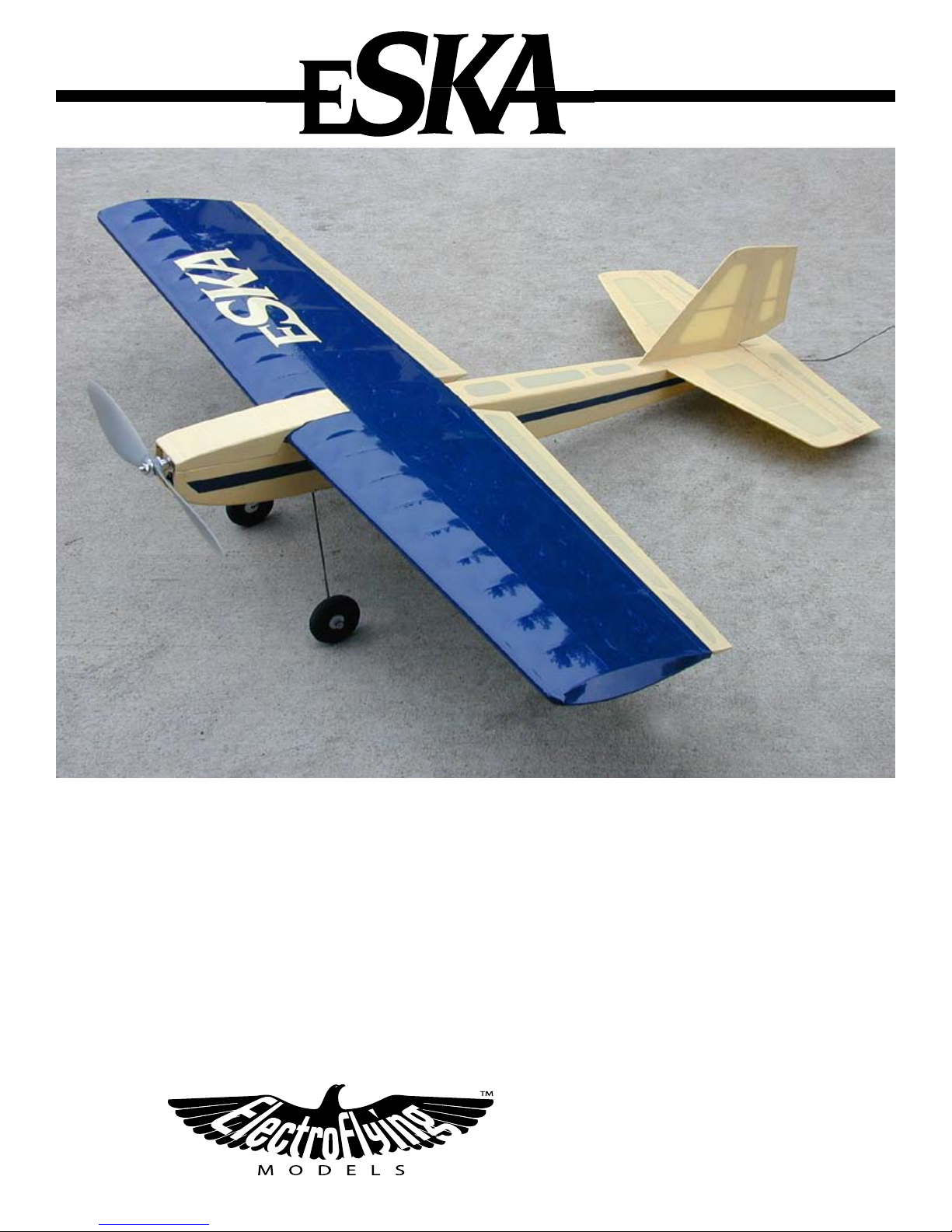
Tail Group Construction
Start the Horizontal Stabilizer and Elevator construction by
covering the Plan with wax paper to protect the Plan and keep the
parts from sticking to it. The Stabilizer and Elevator are constructed
from 1/8" balsa stock.
2 Position and pin laser cut Balsa pieces HS1 through HS5
over Plans. Use a straightedge to keep the TE of the Stab straight.
Note: You should build the Stabilizer bottom side up with the part
labels up as shown here. The Rudder Push Rod Slot will be on the
opposite side from the Top View shown on the Plans.
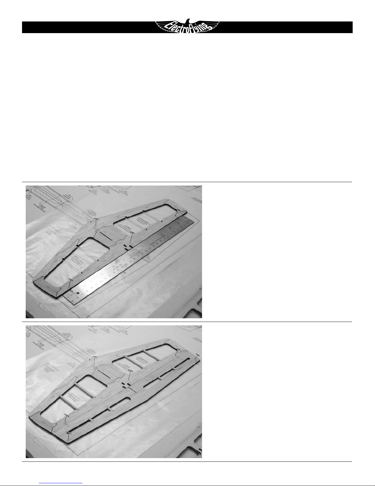
3 Glue all Joints.
4 Position Elevator near TE of the Stabilizer.
5 Cut and glue 1/8" sq. Balsa Sticks between LE and TE of
Stabilizer and Elevator as shown on plans.
eSKA - INSTRUCTIONS 5
M O D E L S
6 Start the Vertical Fin and Rudder construction by covering
the Plan with wax paper to protect the Plan and keep the parts
from sticking to it. The Vertical Fin and Rudder are constructed from
1/8" Balsa stock.
7 Position and pin laser cut Balsa pieces F1 through F4 over
Plans and CA in place.
8 If you will not be using a Rudder control, glue the Rudder to
the TE of the Fin.
9
Cut and glue 1/8" sq. Balsa Sticks between LE and TE of Fin
and Rudder.
Sand Stabilizer, Elevator, Fin and Rudder flat. Round LE of
Fin and top of Rudder. Round LE of Stabilizer.
Taper TE of Rudder and Elevator to match the profile on the
plans. The Rudder and Elevator should be 1/16" Thick at the Trailing
Edge.
2
Bevel the LE of the Elevator as shown on plans.
3
If you plan to use a Rudder Servo, bevel the LE of the Rud-
der as shown on the plans.
Note: Your finished Fin, Rudder, Stabilizer and Elevator should look
like this when your done. They should weigh less than 0.5 oz. after
sanding. You can harden all the Balsa corners with Thin CA for a little
more durability.
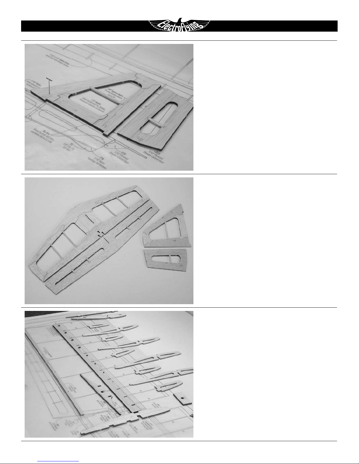
Wing Construction
Start the wing construction by covering the Wing Plan with
4
wax paper to keep the wing from sticking to it. The Wing is built topside-up over the plans.
Note: You will build the Left Wing Panel first. The Left Wing Panel
is lifted 1/2" at Rib 11 for the correct dihedral, then the Right Wing
Panel is built onto the Left Wing Panel.
5
Locate the wing pieces and lay them out in order so you
don't assemble them in the wrong order. Be careful, there is only a
small difference between each Wing Rib. Rib labels should be topside-up when they are glued to the Wing Spar. Check and doublecheck before you glue each Rib in place, you don’t want to have to
build another wing.
eSKA - INSTRUCTIONS 6
M O D E L S
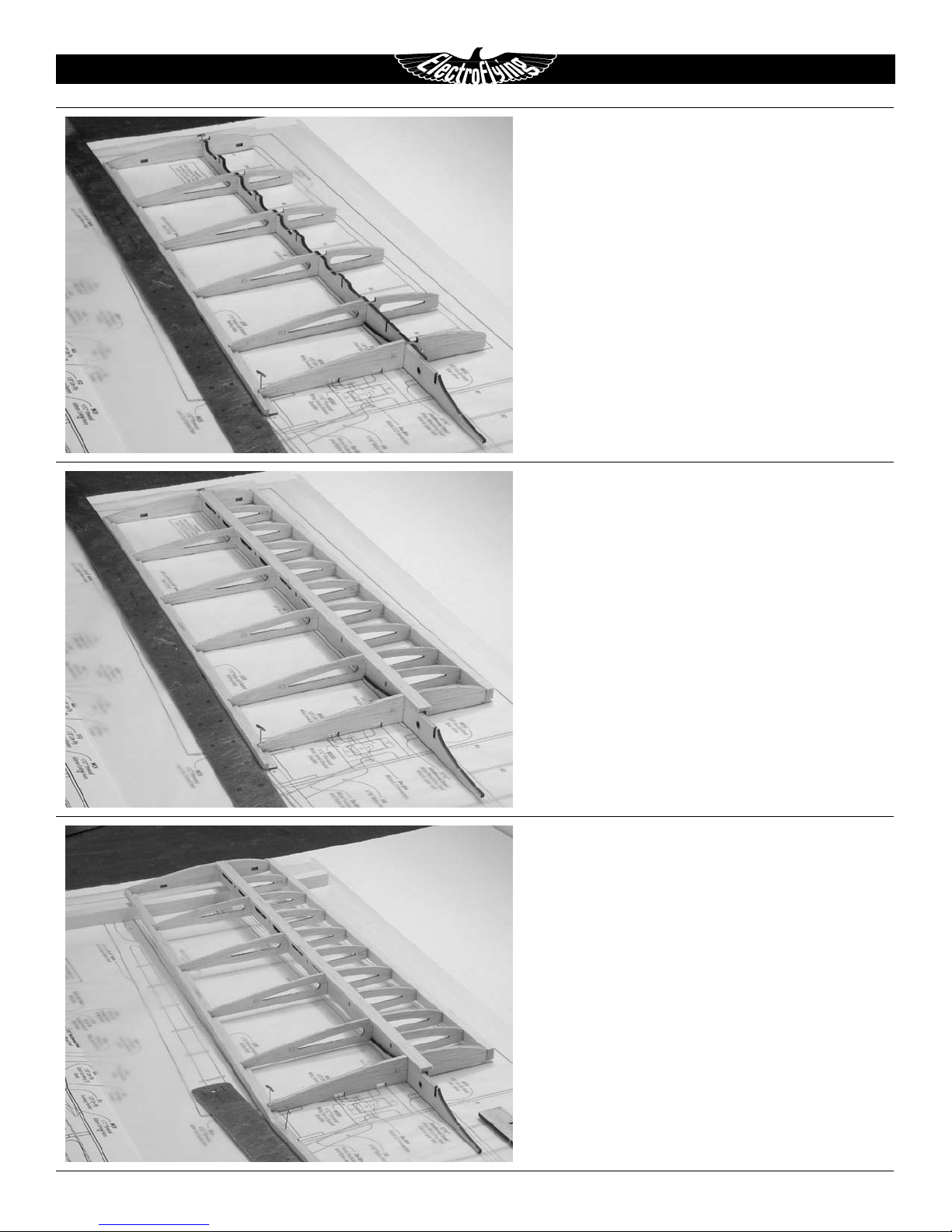
6 While holding the laser cut 1/8" Balsa Wing Spar (WS)
and 1/8" Lite-Ply Rear Spar Joiner (RSJ) together, slide the laser cut
1/16" Balsa Rib 1 (R1) into slot. Glue Joiner to Spar with Thin C/A.
7
Glue laser cut 1/16" Balsa Left Bottom Trailing Edge (LBTE)
to a 1/8"x 1/4"x 15-1/4" Balsa Trailing Edge. Use a straightedge to
keep TE straight. Refer to plans for alignment.
8
Position Wing Spar, Joiner and Rib 1 over plans and pin in
place. Position Trailing Edge assembly over plans Align the root end
with the center of the Wing.
9
Position Trailing Edge over Plans. Ribs fit in notch of LBTE
and against the vertical edge of the Trailing Edge. Glue the rear of
Rib 1 to the Trailing Edge.
2
Glue the laser cut 3/32" Balsa Rib 11 (R11) and Wing Tip
(WT) to end of Spar. Align Rib 11 and TE with Plan and pin in place.
2 Slide the laser cut 1/16" Balsa Full Ribs 3, 5, 7 and 9 (R3, R5,
R7 & R9) into slots on Spar. Glue Ribs to the TE, BUT NOT the Spar.
22 Glue the 1/4"x 3/8"x 15" Balsa Leading Edge to front of Rib
1 and Rib 11. Adjust the other Ribs so they line-up with the Leading
Edge and glue in place at the leading edge and at the Spar.
23 Slide the laser cut 1/16" Balsa Sub Ribs 2, 4, 6, 8 & 10 (R2,
R4, R6, R8 & R10) into place on Spar and line-up front tips with the
Leading Edge. Glue Sub Ribs to Spar and LE.
24 Position 1/8"x 3/8"x 15-1/4" Balsa Top Wing Spar in Rib
slots. Align root end with Wing center. Glue in place. Trim excess off
at Rib 11.
25 Remove pins near Wing Tip and tip Wing up. Place a 1/2"
spacer between building board and Wing at Rib 11. This will set the
correct dihedral as you build the Right wing half onto the completed
Left Wing half.
26 Locate the laser cut 1/16" Balsa Right Bottom Trailing Edge
(RBTE) and 1/8"x 1/4"x 15-1/4" Balsa Trailing Edge. Make up the
other Trailing Edge assembly as before.
27
the two TE root ends together.
Position Trailing Edge over Plans and pin in place. Glue
 Loading...