

Electro Detectors EDA-R5000 Zerio plus Installation Instructions Manual
Electro-Detectors
0359
Electro Detectors Ltd.
Electro House
Edinburgh Way
Harlow, Essex
CM20 2EG, UK
EN54-7:2000+A1:2002+A2:2006
EN54-25:2008
0359-CPR-00229 (2014)
DOP_EDA_R5000
EDA-R5000
Radio smoke detector for use in
fire detection and fire alarm
systems for buildings.
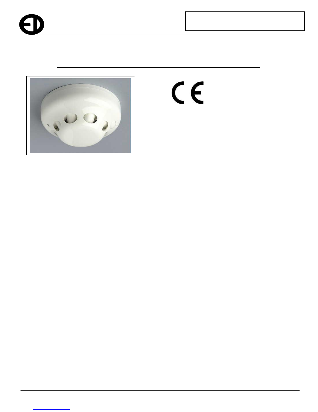
EDA-R5000 Radio Smoke Detector Installation Instructions
The EDA-R5000 Radio Optical Smoke Detector is used as part of the Zerio Plus Radio Fire Alarm System. It cannot be
used with other ranges of Electro-Detectors products.
To fix the unit to the ceiling
The smoke detector should be fitted in an appropriate position as detailed in BS5839 Part 1. The base plate should be
separated from the unit by rotating the detector anti-clockwise and pulling apart. The base should be screwed to a flat
surface using 2 x No 6 screws of appropriate length for the material that the unit is being mounted on. It is
recommended that the base should be used as a template for the screw holes. If the surface is not flat, the unit may
buckle and cause tamper conditions, when screwed tightly to the surface. It is recommended that the units not be
secured too tightly or a rigid mounting plate be fixed to the wall first. The units should not be fitted covering holes in
ceilings where water could possible drip through. Any hole should be made good prior to installing the detector. The
unit should be fitted away from any metal objects or electrical items to avoid radio interference and a radio survey for
the position should have been carried out prior to installation.
Adding the device to the system
Before the unit will operate on a system, it must be programmed via the control panel. To program the unit the panel
must be set in the appropriate mode to add a device to the system. If a device is being added or replaced on the system
then the appropriate menu option should be selected on the control panel. Please refer to the panel manual for further
information. Before adding/replacing the device on the system you will need to know what unit number/address the unit
is to be programmed to. The zone number, sensitivity and text location information should also be to hand but this can
be added/changed later.
Zone Number
The zone number is a logical way of grouping devices and is used as a way of indicating where the alarm is in a
building. Careful attention to BS5839 should be exercised when allocating devices to zones and would usually be
defined when the system is designed. The number of zones available depends on the type of control panel that is being
installed. There are 8, 20 and 100 zone models available.
EDA-R5000 Installation Manual Page 1 of 3 Ref: EDA_R5000_Install_V104.doc
Zerio Plus

Electro-Detectors
Sensitivity
The sensitivity can be adjusted by the control panel to the following settings.
High: 0.08dB/m (1.8%)
Medium: 0.12dB/m (2.7%) Type approved to EN54 Part 7
Low: 0.20dB/m (4.4%)
Alarm Verify
The time period, in seconds, that a detector remains in alarm before sending an alarm signal.
Range: 1 to 20 seconds
The recommended value which conforms with third party type approval tests is 2 Seconds
To put the smoke detector into log mode, follow the procedure below:-
1. The panel will need to be put into ‘add device’, ‘replace device’ or new set-up mode
2. Remove the base by rotating the detector anti-clockwise and pulling apart.
3. Ensure the power jumper is removed.
4. Press and hold the unit removal peg and the reset button on the front of the detector simultaneously.
5. With these buttons both pressed down, fit the power link.
6. If the mode is successfully selected the LED on the front of the unit will glow green.
7. Both buttons can now be released.
8. The panel will indicate that it has found a device of type smoke detector.
9. Confirm this on the panel and select the correct zone number.
10. The panel will now ask whether to use default values or custom settings. Select which option you require.
Default values will meet the relevant parts of EN54.
11. Follow the instructions on the screen selecting the appropriate values. The selections can be made by using the
cursor keys. The available settings in the advanced menu, which are described above, are as follows.
Zone Number
Sensitivity
Alarm Verify
Fitting the unit to the ceiling.
If not already fitted, the power link should be fitted on the ON position. When applied, the unit will beep and the LED
will flash initially green. It will then flash red once a second indicating the unit removal condition. When fitting the unit
to its base the red marking on the base should be aligned with the led on the outer case. The detector should be located
in the base and rotated clockwise. Once mounted correctly press the reset button for about a second until it beeps. The
LED should stop flashing if the unit is mounted correctly.
Should enough smoke enter the chamber, the unit will indicate the alarm condition by illuminating the LED red. The
internal buzzer on the detector will also beep. An alarm transmission will be made to the control panel and the alarm
will be indicated on the panel.
To change the battery in the detector:- replacement part: 1 x EDA-Q690
The battery should last approximately seven years in the smoke detector. Always use batteries supplied by Electro
Detectors otherwise this will invalidate the certification. Many similar battery technologies are available but only the
ones that meet certain properties can be used with these units. The battery pack is fitted with 2xAA Lithium Thynol
Chloride cells. Min voltage 3.0V, Max 3.7V. When the battery is approaching its end of life the unit will transmit a low
battery condition, which will be indicated on the control panel. The system will still function for at least a further 60
days in this condition before the unit fails to operate. Once the batteries are too flat to operate, the unit will either
EDA-R5000 Installation Manual Page 2 of 3 Ref: EDA_R5000_Install_V104.doc
 Loading...