

Electrocube RC NETWORKS ENGINEERING GUIDE
®
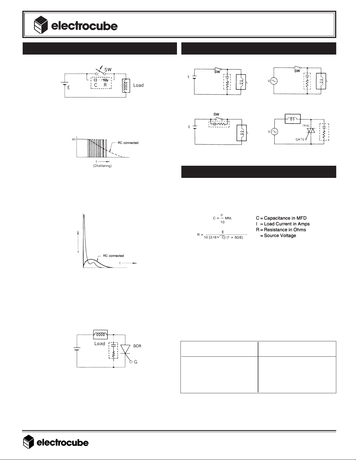
EFFECT OF RC NETWORKS APPLICATION EXAMPLES
ARC SUPPRESSION
RC NETWORKS
ENGINEERING GUIDE
At the moment of switch opening, the RC combination
absorbs and suppresses the energy of the arc by letting it
bypass the switch.
DAMPING OSCILLATION
The RC combination absorbs the high frequency oscillations
caused by mechanical vibrations such as relay contact chattering.
Similarly, the oscillations created by arcing are also averaged and
suppressed by the RC combination regardless of their origin.
BACK ELECTROMOTIVE FORCE SUPPRESSION
With back electromotive force due to inductance, the surge
voltage peak is suppressed by conducting it through the RC
circuit on the low impedance side. the peak is absorbed by the
capacitance of RC. The waveform is averaged and smoothed
by the time constant of the RC; thus generated noise is
eliminated or substantially minimized.
DV/DT SUPPRESSION
Standard example in AC circuitsStandard example in DC circuits
Standard example in DC circuits
For phase control circuits employing
SCR or TRIAC, etc.
DETERMINING RC VALUE
In general, the calculated RC value is difficult to determine
using the following formula. This is due to contributing factors
such as equipment wiring and component locations which can
vary from machine to machine.
E
The best way to determine the values needed is to obtain a
storage oscilloscope and match combinations of resistors and
capacitors while viewing the amount of spike reduction on the
oscilloscope. The user should change the combination of R & C
until the optimum spike reduction is achieved.
Electrocube has determined that the best overall combination is
0.47-.50 Mfd @ 220W. This combination seems to work for 90%
of the applications. The voltage should be selected for the
normal DC or AC voltages, however, the designer must take
into consideration the peak voltages involved.
The resistor wattage depends upon the number of times per
minute the circuit is activated. As a general rule of thumb, the
following chart should be considered.
The RC combination allows the dv/dt of the “on” and “off”
operation of thyristors or similar devices to decrease; thus surge
voltages are suppressed and semiconductor elements are
protected. Even in the case of zero crossing circuits, such as AC
circuits, protection is necessary since harmonic noise occurs
when there is a gap between phases of current and voltage of
the load circuit.
1307 S. Myrtle Ave. • Monrovia, CA 91016 • TEL: (626) 301-0122 • FAX: (626) 357-8099
®
e-mail: sales@electrocube.com • Internet: www.electrocube.com • (IR: 9/99)
CIRCUIT ACTIVATION RESISTOR
TIMES/MINUTE WATTAGE
1-3 1/2
4-5 1
6-9 2
10-15 5
>15 10
The chart and formula are guidelines to give the user a starting
point from which to work. The final selection must be evaluated
in the application to determine its acceptability.
 Loading...