

ElectroCraft IQ 2000, IQ 5000 Instruction Manual

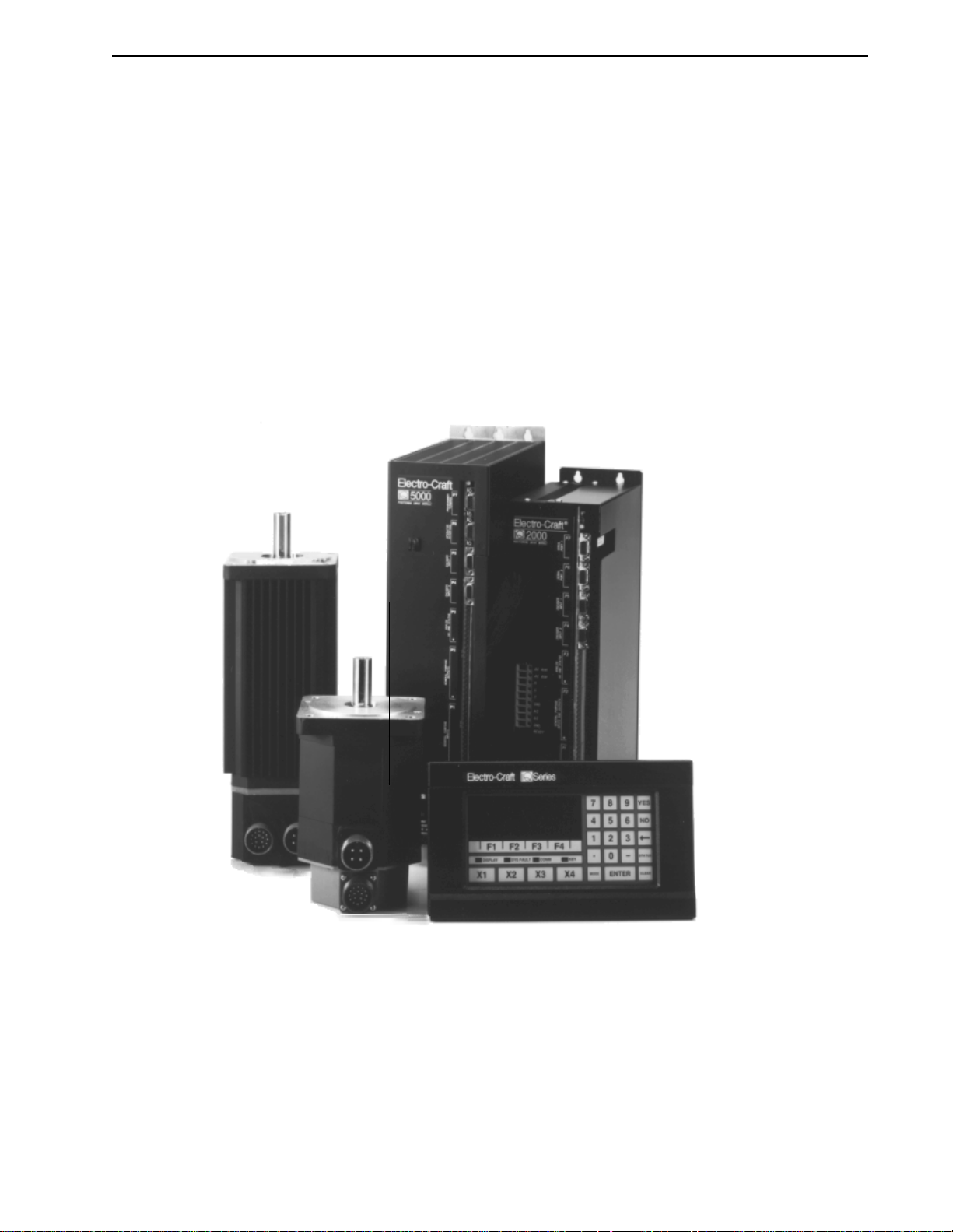
IQ 2000/5000
Positioning Drive
Modules
Instruction Manual
Electro-Craft
SERVO SYSTEM S
A Rockwell Business
Electro-Craft
6950 Washington Avenue South
Eden Prairie, MN 55344
T HE RIGHT COMPANY. THE RIGHT SOLUTION.

Product Notice
Use of IQ 2000/5000 Positioning Drive Modules
IQ 2000/5000 Positioning Drive Modules (PDM) are int ended for use as transistorized electronic amplifiers
powering servo motors in machinery. As such, they must be part of a controlled system that includes a
controlling dev ice. They a re n ot intende d to independ ently contr ol a motor. Inst ructions in the motor and
control system manuals must be observed; this document does not replace those instructions.
Unless specified otherwise, IQ 2000/5000 PDM are int ended for use in a normal indust rial env ir onmen t,
installed in a suitable electrical cabinet without exposure to excessive or corrosive moisture or abnormal
ambient temperatures. T he exa ct oper ating con ditions may be established by referring to the data for t he
PDM. The connecti on and contr ol of PDMs i n machinery is a skilled opera tion, disassembly or repair must
not be attempted. In the event that a PDM fails to operate corr ectly , con tact the place of purchas e for return
instructions.
Safety Notes
There are some possible hazards associated with the use of Positioning Drive Modules. The following
precautions should be observed. Specific Warnings and Cautions are listed on the back of the Title Page
to the manual.
Installation and Maintenance: Installation and maintenance or replacement must be carried out by suitably qualified service perso nnel, paying particula r attention to possib le electrical and mechan ical hazard s.
Weight: PDMs are heavy, the center of gravity may be offset and removable covers shield internal components. When handling, take appropriate precautions and lift the equipment using permanent, fixed
surfaces, such as the ba se; avoid lift ing the dev ice using protect ive cover shi elds that ma y be loose . Bewar e
of sharp edges; use protective gloves when handling such assemblies.
Flying Leads and Loose Cable s: Ensure that flying le ads or loose cables are suitably restrained, to pr event
snagging or entanglement, or are disconnected before carrying PDMs with such leads or cables.
Generation: If a motor is driven mechanically, it may generate hazardous voltages which are conducted
from its power input terminals to the PDM. The power connector must be suitably guarded to prevent a
possible shock hazard.
Loose PDMs: When running an unmounted PDM, ensur e t hat t he coolin g fan is adequa tely guar ded and
sufficient airflow is provided around the PDM to ensure adequate cooling. The mounting surface of the
PDM is a heatsink and its surface temperature may increase when the PDM is operating. If a motor is
connected to the PDM, remove the key which otherwise could fly out and r estrain the motor b efore applying power to the PDM.
Damaged cables: Damage to cables or connectors may cause an electrical hazard. Ensure there is no
damage before energizing the system.
Supply: PDMs connect to a permanent main power source; not a portable power source. Suitable fusing
and circuit protection devices are required. Consul t the instr uc ti ons an d adhe r e to loc al an d nationa l
regulations before connecting and energizing the PDM.
Safety Logic Signals: Logic sig nals from the PDM are interr uptible signals ; they are r emoved when pow er
is removed from the PDM. Consult the manual for information on auxiliary pow er connections th at may
be employed when these signals are used for safety purposes.
Safety Requirements: The safe incorporation of IQ 2000/5000 Positioning Drive Moduless into a machine
system is the respon sibility of the machine designer , w ho should comply with the local safe ty requirements
at the place where the machine is to be used. In Europe this is likely to be the Machinery Directive, the
ElectroMagnetic Compat ibility Dir ective and the Low Voltage Directive. In the United States th is is likely
to be the National Electrical Co de.
Mechanical Connection: PDMs must be installed in side an electrical cab inet that provid es environment al
controls and prot ection . I nstallation information for the PDM is prov ided in th e manua l an d list th e mi nimum installation requirements for the PDM are provided in the manual. Motors and controlling devices
that connect to the PDM should have specifications that complement the capabilities of the PDM.
Motors: Motors con trolled b y the PDM should only connect to t he PDM; they should n ot connect dir ectly
to the AC line. Use of custom mo tors requir es the en tering of a va lid thermal time c onstant, ot herwise the
motor overload protection will not function properly.
P/N 0013-1027-005 Rev A

IQ 2000/5000
Positioning Drive
Modules
Instruction Manual
P/N 0013-1027-005 Rev A
Electro-Craft
SERVO SYSTEM S
A Rockwell Business
Electro-Craft
6950 Washington Avenue South
Eden Prairie, MN 55344

© 1998 Rockwell International Corporation. All rights reserved.
Printed in the United States of America.
Information contained in this manual is subject to change without notice.
Electro-Craft is a trademark of Rockwell Automation.
Other trademarks cited are the property of their respective owner.
P/N 0013-1027-005 Rev A

IntroContents
Contents Intro-3
List of Figures Intro-7
List of Tables Intro-9
CHAPTER 1 Getting Started
Purpose of this manual....................................... 1-1
Functional Description .. ............. ............. ........... 1-2
IQ2000/5000 System Overview................ ............. ..... 1-2
IQMaster for Windows...................................... 1-2
Positioning Drive Module (PDM)....................... ......... 1-2
Power Supply Module (PSM).................. ............. ... 1-4
Motor........... ............. ............. ........... 1-4
Operator Terminal......................................... 1-4
Personality Module (PM)..................... ............. ... 1-4
Manuals ......................................... ..... 1-4
Personal Computer (PC)........... ............ ............. . 1-5
Option Cards......................................... ... 1-5
Accessories.................................... ......... 1-6
Contents
CHAPTER 2 Installation
Fusing Requirements........................................ 2-2
IQ-2000 Short Circuit Protection............................ ..... 2-2
IQ-5000 Short Circuit Protection............................ ..... 2-2
Personality Module Installation.............. ............. ....... 2-3
Installing the Personality Module (PM)............. ............. ... 2-4
System Firmware Installation................................. ... 2-4
Installing the Firmware EPROMs....................... ......... 2-5
Jumper and DIP Switches... ............. ............. ......... 2-5
Option Card Installation ................................. ..... 2-6
IQ-2000......................... ............. ......... 2-6
IQ-5000......................... ............. ......... 2-7
Mounting............................................... 2-8
Environment..... ............. ............ ............. . 2-8
Ventilation..................... ............. ........... 2-8
Transformer Sizing. ............. ............ ............. . 2-9
Mounting Requirements..................................... 2-9
IQ-5000 Positioning Drive Module and Power Supply Module . . . . . . . . . . . . . . 2-13
PSM Auxiliary Transformers................................ .. 2-14
Motors ..................... ......................... 2-14
Operator Terminal........................................ 2-15
24VDC Sourcing I/O Conversion Card ........................... 2-16
System Installation for Electromagnetic Compatibility.................... 2-17
Filtering.......................................... .... 2-18
AC Line Filter Selection..................................... 2-19
Grounding............................................ 2-20
Shielding and Segregation................................... 2-20
IQ 2000/5000 Installation Manual

Intro-4 Contents
Bonding Your System ...................................... 2-23
Bonding Multiple Sub Panels............... ............. ...... 2-24
Regulatory Requirements..................................... 2-24
IQ 2000 Installation for European Directive Compliance.................... 2-24
Electromagnetic Compatibility Directive........................... 2-24
Motors and Cables.................................. ...... 2-26
Low Voltage Directive.................................... .. 2-27
CHAPTER 3 Wiring
System Power Connections .................................. .. 3-1
IQ-2000 Positioning Drive Module (PDM) ............. ............. 3-1
IQ-5000 PDM.. ............. ............. ............. .. 3-2
Operator Terminal........................................ 3-6
Motor Power Connections.................................... 3-6
Control Connections ........................................ 3-8
Digital Inputs and Outputs . . . . . . . . . . . . . . . . . . . . . . . . . . . . . . . . . . . 3-9
Digital Inputs . . . . . . . . . . . . . . . . . . . . . . . . . . . . . . . . . . . . . . . . . . . 3-10
Digital Outputs . . . . . . . . . . . . . . . . . . . . . . . . . . . . . . . . . . . . . . . . . . 3-11
Connecting Inputs and Outputs Together. ............. ............. 3-11
Analog Input ...... ............. ............ ........... 3-12
Analog Output.......................................... 3-13
Monitor Output.......................................... 3-13
Ready Relay Output ....................................... 3-13
Enabled Relay Output...................................... 3-14
Encoders............................ ............. ...... 3-14
Step and Direction Inputs.................................... 3-17
Serial Ports...................................... ...... 3-18
Expansion I/O and Memory ...... ............. ............. .. 3-23
Cables ................ ............. ............. ...... 3-31
CHAPTER 4 Applying Power for the First Time
Start-up Procedure for IQ-2000 PDMs .............................. 4-1
Start-up Procedure for IQ-5000........ ............. ............. 4-3
Power Supply Module...................................... 4-3
Start-up Procedure for PDM.................................. 4-3
Motor Start-up Procedure.......................... ........... 4-5
Operator Terminal......................................... 4-5
Backing Up the Personality Module............................... 4-5
CHAPTER 5 Diagnostics/Troubleshooting
Light Emitting Diodes (LED)................................... 5-1
Positioning Drive Module STATUS LED..................... ...... 5-1
DC Bus Power (IQ-2000)... ............. ............. ........ 5-1
Operator Terminal......................................... 5-2
Operator Terminal Status Screens . . . . . . . . . . . . . . . . . . . . . . . . . . . . . . . 5-2
Personality Module Default Initialization............................ 5-3
Error Messages and Error Output (08) . . . . . . . . . . . . . . . . . . . . . . . . . . . . . . 5-3
CHAPTER 6 Specifications
IQ-2000 Series Specifications.................................... 6-1
IQ-5000 Series............................................ 6-2
Operator Terminal......................................... 6-2
P/N 0013-1027-005 Rev A

Transformer Specifications..................................... 6-3
CHAPTER 7 Component Ordering Information
Contents Intro-5
Our Warranty
Help-1
Documentation Improvement Help-2
EU Directives Help-3
Index of Topics Help-7
Product Support Help-13
IQ 2000/5000 Installation Manual

Intro-6 Contents
P/N 0013-1027-005 Rev A

IntroList of Figures
CHAPTER 1 Getting Started
IQ2000/5000 Product Family................................. 1-1
IQ2000/5000 System Components ............................. 1-3
IQ2000/5000 Operator Terminal............................. .. 1-5
CHAPTER 2 Installation
Location of Personality Module................................ 2-3
Location of System Firmware................................. 2-4
Location of Jumper and DIP Switch ..................... ........ 2-5
IQ-2000 Option Card Installation......................... ...... 2-6
IQ-5000 Option Card Installation......................... ...... 2-7
IQ-2000 PDM-10, PDM-20 and PDM-30 Mounting..................... 2-10
IQ-2000 PDM-75 Mounting.. ............. ............. ...... 2-11
IQ-2000 PDM-150B Mounting................................. 2-12
IQ-5000 PDM & PSM Mounting.............................. .. 2-13
PSM Auxiliary Transformer Mounting... ............. ............ 2-14
Operator Terminal, Dimensions....... ............. ............ 2-15
24VDC I/O Conversion Card Mounting Dimensions............... .... 2-16
EMI Source-Victim Model................................... 2-17
AC Line Filter Installation. ............. ............. ........ 2-19
Single Point Ground Types.................................. 2-20
Torroid Encoder Shielding Method for Brushless Servo Motors . . . . . . . . . . . . . 2-22
Motor Power Winding Methods to M inimize Noise Emissions . . . . . . . . . . . . . . 2-22
Recommended bonding practices. . . . . . . . . . . . . . . . . . . . . . . . . . . . . . . 2-23
Bonding Multiple Sub Panels and Cabinet...................... .... 2-24
Recommended IQ-2000 Installation for EMC . . . . . . . . . . . . . . . . . . . . . . . . 2-25
Emergency Stop Contactor Wiring.............................. 2-28
IQ-5000 Transformer Outline Diagram........................ .... 2-29
IQ-5000 Transformer Load Regulation Curve.................. ...... 2-30
PSM-AUX Outline and Connection Diagram........................ 2-31
IQ-2000 Transformer Outline Diagram........................ .... 2-32
IQ-2000 Transformer Load Regulation Curve.................. ...... 2-33
External Shunt Mounting and Connection Diagram.................... 2-34
External Shunt Wiring Examples............................... 2-34
24V Sourcing I/O Conversion Card............................. 2-35
List of Figures
CHAPTER 3 Wiring
PSM Interface – Internal Circuit Examples ......................... 3-3
PSM Interface – External Connection Examples . . . . . . . . . . . . . . . . . . . . . . 3-4
Power Supply Module Jumper Location ..... ............. ........ 3-5
Shunt Fuse Location...................................... 3-5
Operator Terminal Power Connections ........................... 3-6
Motor Power Connections ....... ............ ............. .. 3-6
Motor Power EMC Shield Connection.................. .......... 3-7
PDM Control Connections................ ............. ...... 3-8
Typical Digital I/O Wiring . . . . . . . . . . . . . . . . . . . . . . . . . . . . . . . . . . 3-9
Analog Input and Output – Typical Internal Circuits ................... 3-12
IQ 2000/5000 Installation Manual

Intro-8 List of Figures
Enable and Ready Relay – Typical Internal Circuits.................... 3-13
Encoder Input Circuitry Example. ............. ............. ... 3-14
Encoder 1 Connections............................... ..... 3-15
Encoder 2 Connections............................... ..... 3-16
Step and Direction Input Connections . ............ ............. . 3-17
Personal Computer RS-232C Connections......................... 3-19
IQ Operator Terminal RS-232 Connections ........................ 3-20
IQ Operator Terminal RS-422 Connections................ ......... 3-21
IQ Operator Terminal RS-422 Multi-Drop Connections.................. 3-21
Dip Switch SW1........................................ 3-21
Dip Switch SW1 Set For Address 5 Example........................ 3-21
Dip Switch SW1-7 Set ON For Daisy-Chain Mode Example............... 3-22
RS-422 Multi-Drop Connections............................... 3-22
RS-232C Daisy-Chain Connections............................. 3-22
IQ-5000 Power Wiring .................................... 3-25
PSM-AUX Connections.................................... 3-26
IQ-2000 Power Wiring for PDM-10, -20 and -30 . . . . . . . . . . . . . . . . . . . . . . 3-27
IQ-2000 Power Wiring for PDM-75.......................... ... 3-28
IQ-2000 Power Wiring for PDM-150B ........................... 3-29
Expansion Card I/O Connections........................... ... 3-30
IQ P7 to Operator Terminal (P/N 9101-2025) . . . . . . . . . . . . . . . . . . . . . . . 3-31
IQ P6 to PC Serial Port (9 pin) (P/N 9101-2024)...................... 3-31
IQ P4 or P5 to Auxiliary Encoder (Unterminated) (P/N 9101-2031). . . . . . . . . . . 3-32
IQ P4 to P4, 2 foot (P/N 9101-2127)............. ............. ... 3-33
IQ P5 to S-, H-, or F-Series Motor Encoder (P/N 9101-2027) . . . . . . . . . . . . . . . 3-33
CHAPTER 4 Applying Power for the First Time
Initialize PM Dialog Box for IQ-2000............................ 4-1
Initialize PM Dialog Box for IQ-5000............................ 4-4
CHAPTER 5 Diagnostics/Troubleshooting
Initialize Personality Module window........................... 5-3
CHAPTER 6 Specifications
CHAPTER 7 Component Ordering Information
P/N 0013-1027-005 Rev A

IntroList of Tables
CHAPTER 1 Getting Started
CHAPTER 2 Installation
Mounting and Related Diagrams ....................................2-1
Maximum Power Losses for IQ-Series Related Products ......................2-8
Suitable AC Line Filter Types .....................................2-18
PDM Current Ratings and Suitable Supply Filters.........................2-26
Roxburgh Filters Available Directly from Rockwell Automation ................2-26
Shielded Motor Power Cables ..................................... 2-26
CHAPTER 3 Wiring
PSM Interface Signals .........................................3-3
Digital Imputs and Assignable Fu nctions ..............................3-10
Digital Outputs and Assignabl e F unctions ............................. 3-11
Analog Inputs and Signal Name .................................3-12
Analog Output and Signal Name ..................................3-13
Monitor Output and Signal Name .................................. 3-13
Ready Relay Output and Signal Name .............................. 3-13
Enabled Relay Output and Signal Name .............................3-14
Encoder 1 and Signal Name .................................... 3-15
Encoder 2 and Signal Name ..................................... 3-16
Step and Direction Inputs and Signal Name ...........................3-17
Host Computer and Signal Name .................................. 3-18
P7 at Serial Port 1 on Operator Terminal ............................3-20
COM1 Connector on back of Operator Terminal.......................... 3-20
P1 and P2 on IQ and Expansion Board Connections ....................... 3-23
P3 Pins on Expansion Card ...................................... 3-24
List of Tables
CHAPTER 4 Applying Power for the First Time
CHAPTER 5 Diagnostics/Troubleshooting
Power Supply Module LEDs (IQ-5000 s ystems only) .......................5-2
Variables Available on Status Screens .................................5-2
Error Messages ...............................................5-4
CHAPTER 6 Specifications
PDM-10, PDM-20, PDM-30, PDM-75, and PDM-150B Specifications .............6-1
PDM-25, PDM-50, PDM-100, and PDM-150/150X Specifications ................6-2
Operator Terminal Specifications. ....................................6-2
Single Phase Transformer Specifications ...............................6-3
Three Phase Transformer Specifications ...............................6-3
CHAPTER 7 Component Ordering Information
Part Numbers of Positioning Drive Modules .............................7-1
Part Numbers of Power Supply Modules ...............................7-1
Part Numbers of Cables ..........................................7-2
Personality Module Identification Codes ...............................7-2
Motor Identification Codes .......................................7-3
IQ 2000/5000 Installation Manual

Intro-10 List of Tables
Part Numbers of Motor Mating Connector Kits ............................7-3
Part Numbers of Motor Shaft Seal Kits .................................7-4
Part Numbers of Transformers ......................................7-4
Part Numbers of Interface Cards .....................................7-4
P/N 0013-1027-005 Rev A
CHAPTER 1: Getting Started
Purpose of this manual
This manual describes the function and installation of IQ 2000/5000 Positioning Drive Module
(PDM) products and standard Electro-Craft motors recommended for use with the IQ 2000/
5000 PDM. It is intended for engineers or technicians directly involved in the installation, operation, and field maintenance of the IQ 2000/5000 PDM.
The IQ Master Instruction Manual describes the operation of the IQ Master executive software.
This software package is used to software configure the IQ 2000/5000 products, which are
shown in Figure 1.1. Refer to the IQ Master Instruction Manual for programming and software
related issues.
FIGURE 1.1 IQ 2000/5000 Product Family
IQ 2000/5000 Installation Manual

1-2 Getting Started
Functional Description
The IQ 2000/5000 system is for use as a servo drive and control system in industrial machinery.
It is intended to be use d as a s ystem c omprised o f at le ast a m otor an d a PDM. The P DM is n ot
intended for use with motors other than Electro-Craft motors as specified in this manual. PDMs
are intended to be permanently connected to the supply, not for portable equipment. The motors
are not intended to be directly connected to the supply and must only be connected to a suitable
Electro-Craft drive. The system is intended for use in a normal industrial environment (refer to
Chapter 6, “Specifications”) and precautions must be taken during storage, handling, installation and use to ensure that it does not encounter extreme environments exceeding the
specifications.
The IQ 2000/5000 motion control system is a positioning drive system which integrates a high
performance sinusoidal brushless motor velocity controller and a programmable position controller into a single package. Traditional motion controller architecture uses separate d rive and
position control modules, with an analog interface between individual components. The
IQ 2000/5000 motion controllers use advanced microprocessor technology to control both position and velocity with a single processor, eliminating the need for any analog interface. The
single processor architecture eliminates the problems associated with analog circuitry, such as
offset and thermal drift. Bo th the velocity and position contr ol loops are closed digitally, so gain
parameters are stored as n umbers wh ich give repeatable results over time and from controller
to controller.
The IQ may be used as a distributed motion control element integrated with a host computer
in a flexible automation system or as a stand-alone, programmable motion controller. Optically
isolated I/O and power supplies are integrated into the products.
The electronic gearing feature allows the closed-loop axis to follow a second (master) encoder
at a programmable ratio. A multi-axis addressing scheme (multi-drop operation) allows multiple IQs to be controlled from a host computer over a single serial communications link.
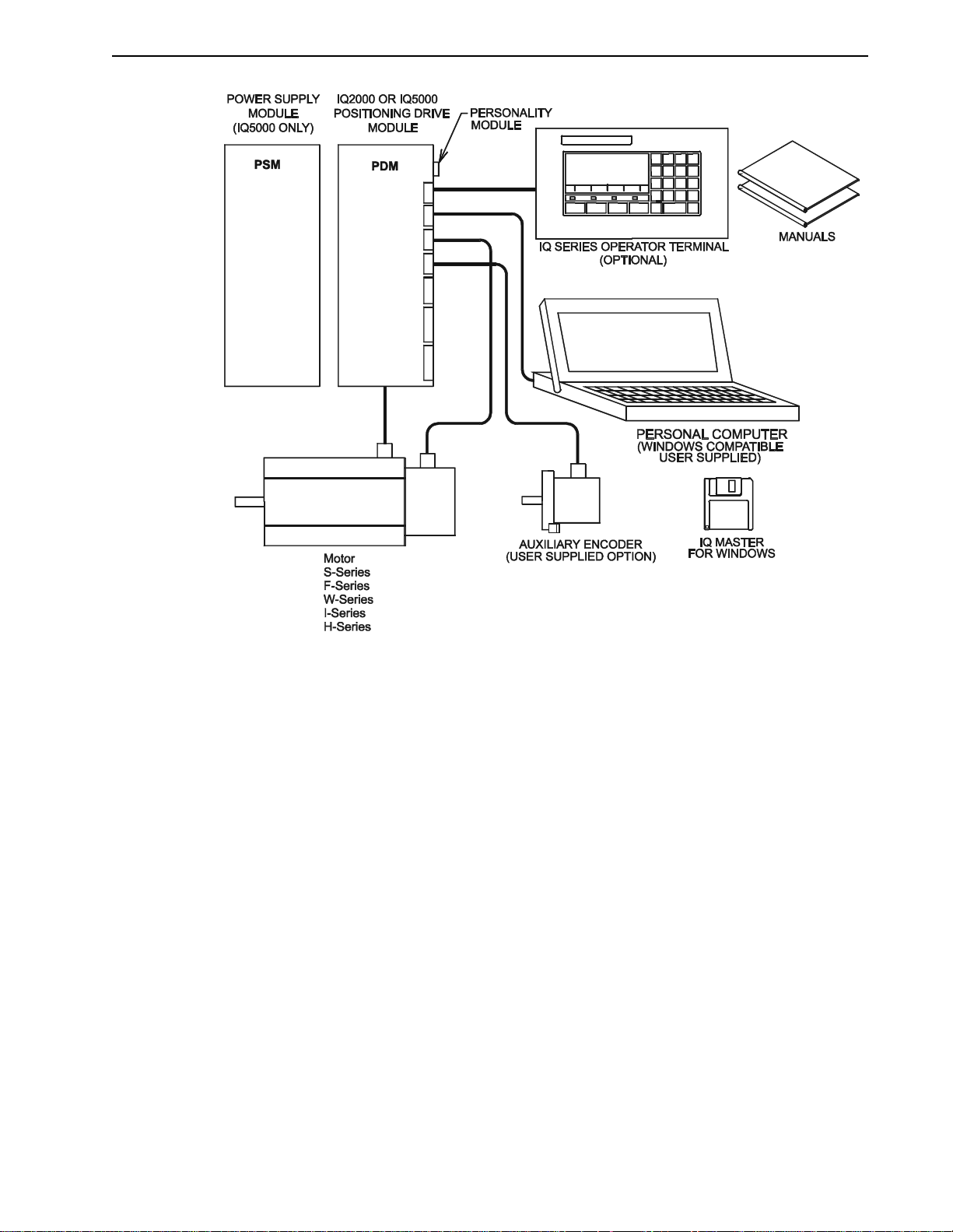
An IQ 2000/5000 system consists of a Positioning Drive Module ( PDM), which controls the
position, velocity and torque of the motor; a Personality Module which plugs into the PDM to
match the controller with the motor used; a brushless motor with an integral optical encoder
for feedback; a Power Supply Module, integral to the IQ-2000 PDMs, and separate for the IQ5000 PDMs; and an optional Operator Terminal. Option cards for I/O or memory expansion or
other application specific functions mount directly on the PDM.
Combinations of matched PDMs and motors are available which provide continuous torques
of 0.34 Nm to 88.14 Nm (3 inch/pound to 750 inch/pound), and speeds up to 6000 RPM.
IQ 2000/5000 System Overview
An IQ 2000/5000 motion control system consists of a number of components connected to
accomplish a specific function. This section provides a brief overview of the various components
of the IQ 2000/5000 motion control system.
IQ Master for Windows
IQ Master is a Windows based software package that provides the user interface to the PDM.
It is used to edit and compile application programs, and to configure, monitor , and troubleshoot
the PDM.
Positioning Drive Module (PDM)
The IQ 2000/5000 PDM is a self-contained single axis programmable motion controller. The
PDM provides control and power for the brushless servo motor. Motion programs are stored
in on board nonvolatile memory . T wo RS -232/RS-422 serial ports provide communications with
the personal computer and the optional Operator Terminal. Optically isolated digital I/O allows
simple machine interfacing and control.
P/N 0013-1027-005 Rev A
Getting Started 1-3
FIGURE 1.2 IQ 2000/5000 System Components
PDMs are manufactured in different packages which cover a wide range of power capability.
The IQ-2000 Series PDMs incorporate an integral power supply in each PDM, and supply con-
tinuous torques of 3 to 450 inch–pounds in combination with standard motors. The IQ-5000
Series PDMs use a separate power supply module, which can be shared among multiple PDMs,
and provide continuous torques of 20 to 750 inch pounds with the standard motors.
IQ-2000 PDMs
The PDM-10, PDM-20, PDM-30, PDM-75, and PDM-150B are rated for 10, 20, 30, 75, and 150
amp peak currents respectively. These modules are packaged with an integral power supply to
achieve a small size.
Input power to a PDM-10 , P DM-20, or PDM-30 is s ingle ph ase 115 or 230 VAC. Input power to
a PDM-75 or PDM-150B is three-phase 115 or 230 VAC. The input power may be optionally
isolated through a transformer. These PDMs have a built-in solid state “soft charge” of the
internal DC bus capacitor. They also include a built-in dissipative shunt regulator that provides
synchronous motor dynamic braking. The PDMs allow use of an optional external shunt resistor
for applications requiring higher shunt power capability than provided by the internal shunt
resistor.
IQ 2000/5000 Installation Manual

1-4 Getting Started
IQ-5000 PDMs
The PDM-25, PDM-50, PDM-100, and PDM-150/150X are rated for 25, 50, 100, and 150 amp
peak currents respectively. These higher power PDM modules use a separate power supply
module (PSM-50 or PSM-125), which may be shared among multiple PDMs to achieve the most
economical system package. Other than the packaging and power ranges, the IQ-5000 is identical to the IQ-2000 from a setup and programming perspective.
Power Supply Module (PSM)
The power supply module is only required for IQ-5000 systems. The Power Supply Module
(PSM) can supply DC power to as many as six PDM modules. The only input to the PSM is 100–
240 VAC single or three phase power. The input power may be optionally isolated through a
transformer. The output is a two wire DC bus. The PSM requires no adjustments, protects itself,
provides troubleshooting diagnostics, and has a built-in solid state “soft charge” of the DC bus
capacitors. It also includes a built-in dissipative shunt regulator that provides quick discharge
of the DC bus capacitors and doubles as an emergency synchronous motor dynamic brake.
Motor
A wide range of Electro-Craft F-Series, H-Series, N-Series and W-Series permanent magnet
synchronous motors, and the I-Series induction motors are available for use with the PDM
modules. Each motor includes an integrally mounted encoder . Most motors ar e available with
options including spring set brake and/or shaft oil seal. Military Standard (MS) connectors are
standard for all H-Series and F-Series motors.
Operator Terminal
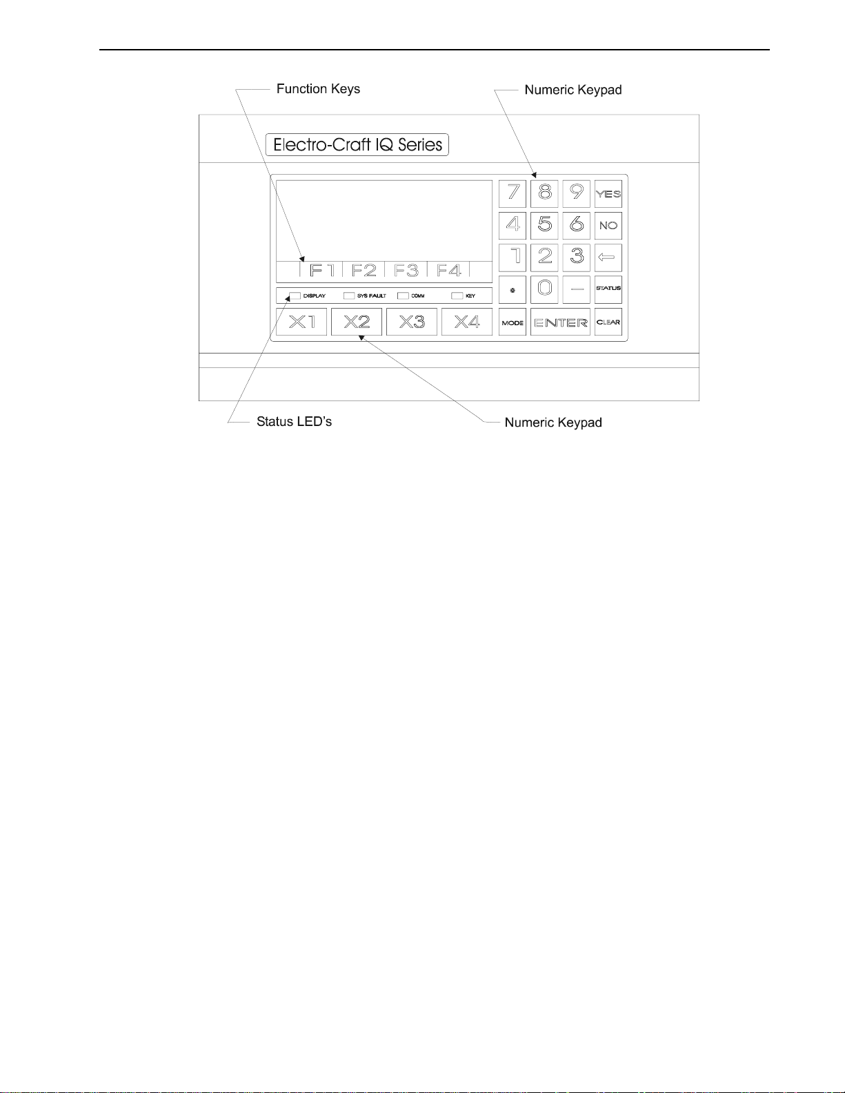
The optional Operator Terminal is a rugged man/machine interface device. It allows the
machine operator convenient access to status information, pr ogram variables, and contr ol functions, plus message display capabilities. The Operator Terminal has a bright 4 line by 20 character
vacuum fluorescent display and a sealed membrane keyboard with tactile feedback.
The Operator Terminal displays multiple status screens for monitoring and diagnostics. Four
soft function keys are available to perform up to twenty-four (24) predefined functions, some
of which are selecting and running a program, jogging the sys tem, and stopping a program.
The user program may display messages and prompts on the screen, and receive input from
the keypad. Four additional user programmable keys provide extra flexibility within a user
program. Input power to the Operator Terminal is 115 or 230 VAC, or optionally 24 VDC or
24 VAC.
Personality Module (PM)
The Personality Module is a nonvolatile memory device which stores the information necessary
to customize an IQ2000/5000 PDM for a speci fic application. The PM holds param eters to match
the encoder feedback, motor and the drive, as well as user programs and parameters. A Personality Module may be physically removed and transferred to another PDM if the replacement
of a PDM is necessary to simplify servicing the machine. The Personality Module data can also
be saved in a computer file and loaded into the IQ 2000/5000 using the File > Transfer dialog
box in IQ Master.
Manuals
The manuals are conveniently broken into two volumes. This manual contains all the information required for mounting and wiring the motor and PDM. The IQ Master Software Manual
contains all the information that a user and programmer requires to quickly setup the PDM and
develop programs for the PDM.
P/N 0013-1027-005 Rev A
Getting Started 1-5
FIGURE 1.3 IQ 2000/5000 Operator Terminal
Personal Computer (PC)
A user supplied Personal Computer is required to run IQ Master software. The minimum computer requirements to run this software are contained in the IQ Master Instruction M a nual.
Option Cards
Each PDM can have an option card mounted on its main control board, inside the PDM cover.
The option card mounting allows either a half-size or full-size option card. The PDM has a
connector that connects the option card to the PDM power supplies and microprocessor through
a ribbon cable.
The option cards currently available include a com bination M emory an d I/O Expan sion Card
and an I/O Expansion Card. Refer to“Part Numbers of Interface Cards” on page 7-4.
Memory and I/O Expansion Card
Additional memory and I/O may be added vwith a Memory and I/O Expansion Card. This
board adds the following memory, input and output capabilities to the PDM.
◆ 32 Kilobytes of additional nonvolatile memory to the base PDM for the storage of up to 32
additional programs
◆ 32 TTL Inputs
◆ 16 TTL Outputs
◆ four 12-bit Analog inputs
IQ 2000/5000 Installation Manual

1-6 Getting Started
I/O Expansion Card
Additional I/O may be added with an I/O Expansion Car d. This board adds the following input
and output capabilities to the PDM.
◆ 32 TTL Inputs
◆ 16 TTL Outputs
NOTE:
The digital inputs and outputs on the I/O expansion cards are 5 Volt TTL signals which are not
optically isolated.
I/O Interface Card
A DIN rail mounted interface card fo r I/O conversion. The interface car d converts the IQ inputs
and outputs from sinking (act ive low), which is common in the USA but unacceptable in Europe,
to sourcing (active high). The interfa ce card must be mounted in the same enclosure a s the drive.
Installation instructions are provided with the card.
Accessories
Transformers
Multi-tap single phase and three phase isolation transformers are available in a variety of power
ratings for line voltage matching. See “Part Numbers of Transformers” on page 7-4.
Auxiliary Power Supply Module (IQ-5000 Only)
An auxiliary power supply module (PSM-AUX) is available to supply DC power to the logic
supplies of up to four PDMs if the PSM is off. The PSM-AUX uses single phase 115 VAC power
as the input. This option is only necessary for the IQ-5000 with the separate power supply
module. The IQ-2000 PDMs with an integral power supply include the auxiliary supply in the
PDM.
The PSM-AUX option is useful if PDM logic power must stay on even when the motor supply
(the PSM) is off. Absolute positioning is on e exa mple of when the PSM-AU X w ould be useful,
since position information is maintained as long as logic power is on. Another example would
be maintaining PDM logic power so the PDM serial interface could be used for troubleshooting
and diagnostics. Refer to Figure 2.24 on page 2-31 for additional information on the use of the
PSM-AUX and optional PSM-AUX isolation transformer. See “Part Numbers of Power Supply
Modules” on page 7-1.
Cables
Motor power cables with connectors are available in four standard lengths 3, 7.6, 15 and 23
meters (10, 25, 50 and 75 ft.). Motor encoder ca bles with connectors an d fifteen pin “D” connectors are available in the four standard lengths. Nine pin serial cables are available in 3 and 7.6
meter (10 ft. and 25 ft.) lengths. See “Part Numbers of Cables” on page 7-2.
Motor Connectors
Mating connectors are available if you choose to build your own motor cables. See “Part Numbers of Motor Mating Connector Kits” on page 7-3.
P/N 0013-1027-005 Rev A

CHAPTER 2: Installation
This chapter explains the physical mounting of each of the individual components associated
with an IQ 2000/5000 system. Refer to the drawings listed below for assistance.
TABLE 2.1 Mounting and Related Diagrams
Figure Part Number Title Page
2.22 9101-0131 IQ-5000 Transformer Outline Diagram 2-29
2.23 9101-0132 IQ-5000 Transformer Load Regulation Curve 2-30
2.24 9101-0134 PSM-AUX Outline and Connection Diagram 2-31
2.25 9101-1056 IQ-2000 Transformer Outline Diagram 2-32
2.26 9101-1057 IQ-2000 Transformer Load Regulation Curve 2-33
2.27 9101-1328 External Shunt Mounting and Connection Diagram 2-34
2.28 --- External Shunt Wiring Examples 2-34
2.29 9103-0152 24V Sourcing I/O Conversion Card 2-35
Prior to installation of the IQ 2000/5000 system, verify that all the necessary components are
available. Ea ch axis of motion req uires an IQ 2000/5000 Positioning Dri ve Module (PDM), either
IQ-2000 or IQ-5000 and a motor. There must be one PDM for each motor. If IQ-5000 PDMs are
used, there must be at least one power supply module for the system.
Optional compon ent s of the system are an IQ 2000/5000 Operator Terminal, a transformer, an
Auxiliary power supply for the IQ-5000, an external shunt for the IQ-2000, and any IQ 2000/
5000 option cards.
A personal computer, with IQ Master software will be required to setup the system. The PC is
customer supplied.
Machines which integrate the PDM must be designed to meet all regulatory requirements for
locations where the machine may be brought into use. In the U.S. these include but are not
limited to UL and NEC requirements. In Europe, machines must comply with the Machinery
Directive and the basic standards which this directive references .
DANGER: Only qualified electrical personnel familiar with the
construction and operation of this equipment and the hazards
!
involved should inst all, adjust, operate, or service this equipm ent.
Read and understan d this ma nual and other appl icable m anuals
in their entirety before proceeding. Failure to observe this precaution could result in severe bodily injury or loss of life.
IQ 2000/5000 Installation Manual

2-2 Installation
Fusing Requirements
Fusing for the IQ-5000 differs from the IQ-2000 in that the IQ-5000 utilizes a separate power
supply . Since the power supply can pr ovide power to up to six drives, the “ 4 times motor FLA”
rule does not apply.
IQ-2000 Short Circuit Protection
In the United States, the National Electrical Code (NEC) specifies that fuse selection must be
based on the motor full load amperage (FLA), which is not to be confused with the drive input
current. The largest fuse allowed under any circumstances is four times the motor FLA. Therefore the largest fuses permissible for use are four times the motor FLA (marked on the motor)
converted to an RMS value. The IQ-2000 has been evaluated and listed by Underwriter Laboratories
(FLA) of the drive.
In almost all cases, fuses selected to match the drive input current rating will me et the NEC
requirements and provide the full drive capabilities. Dual element, time delay fuses should be
used to avoid nuisance trips during power initialization due to inrush current.
Short Circuit Current Rating with No Fuse Restrictions
Suitable for use on a circuit capable of delivering not more than 5000 RMS symmetrical Amperes,
240 Volts maximum.
®
Inc. according to UL 508C, with fuses sized as four times the continuous output current
Short Circuit Current Rating with Fuse Restrictions
Suitable for use on a circuit capable of delivering not more than 200,000 RMS symmetrical
Amperes, 240 Volts maximum, when protected by high interrupting capacity, current limiting
fuses (Class CC, G, J, L, R, T).
Motor Overload Protection
This drive utilizes solid state motor overload protection which operates:
◆ within 8 minutes at 200% overload
◆ within 20 seconds at 600% overload
IQ-5000 Short Circuit Protection
In the United States, the National Electrical Code (NEC) specifies that fuse selection must be
based on the motor full load amperage (FLA), which is not to be confused with the drive input
current. The largest fuse allowed under any circumstances is four times the motor FLA. Therefore the largest fuses permissible for use are four times the motor FLA (marked on the motor)
converted to an RMS value. The IQ-2000 has been evaluated and listed by Underwriter Laboratories
In almost all cases, fuses selected to match the drive input current rating will me et the NEC
requirements and provide the full drive capabilities. Dual element, time delay fuses should be
used to avoid nuisance trips during power initialization due to inrush current.
®
Inc. according to UL508.
Short Circuit Current Ratings and Fuse Requirements
Suitable for use on a circuit capable of delivering not more than 5,000 RMS symmetrical
Amperes, 240 Volts maximum, when protected by
◆ PSM 50: class R fuses rated 40A
◆ PSM 125: class R fuses rated 90A
P/N 0013-1027-005 Rev A
Motor Overload Protection
This drive utilizes solid state motor overload protection which operates:
◆ within 8 minutes at 200% overload
◆ within 20 seconds at 600% overload
Personality Module Installation
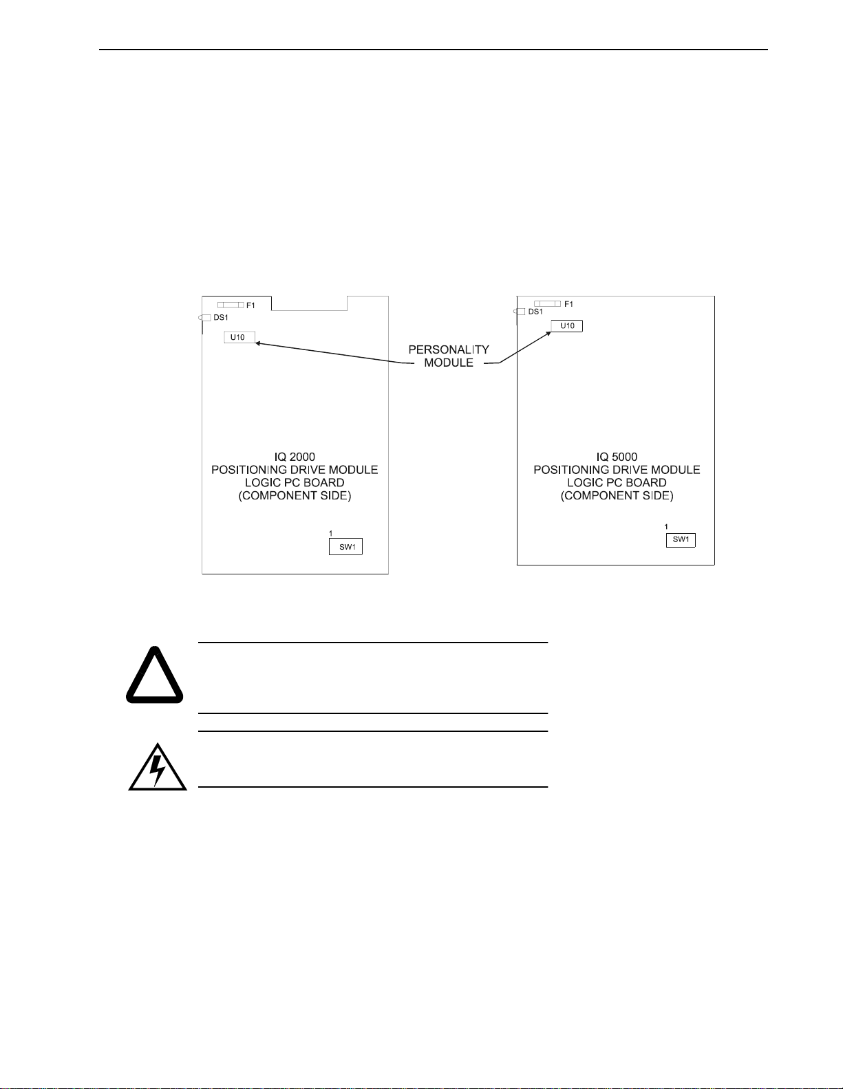
The Personality Module is already installed on the IQ 2000/5000. The following procedure is
to be used if the Personality Module needs to be changed for machine servicing. Refer to
Figure 2.1 for the location of the Personality Module on the IQ 2000/5000 logic board.
Installation 2-3
FIGURE 2.1 Location of Personality Module
CAUTION: Do
power to the PDM is ON. Static electricity can damage the per-
!
sonality module. Wear a conductive wrist strap while handling, or
touch earth ground before handling.
CAUTION: Static electricity can damage Personality Modules.
Wear a conductive wrist strap while handling, or touch earth
ground before handling.
not
install or remove th e personality modul e while
IQ 2000/5000 Installation Manual
2-4 Installation
Installing the Personality Module (PM)
1. Check that power to the PDM is OFF.
IQ-2000: Measure voltage between PDM terminals marked L1 and L2/N (L1, L2/N and
L3 for PDM-75) to ensure incoming power is OFF. Also measure voltage between terminals marked L1 AUX and L2/N A UX, if used, to ensure power is OFF . The green DC BUS
LED and the bicolor STATUS LED should be OFF.
IQ-5000: Measure voltages at Positive and Negative bus terminals to ensure incoming
power is OFF. If a PSM-AUX is used, measure the voltage at L1 and L2 of the PSM-AUX
to ensure that incoming power is OFF
2. Remove PDM cover (IQ-5000 only).
3. Install Personality Module on PDM logic board in socket at location U10. The end of the
Personality Module (PM) with the colored label must be toward the front of the PDM.
4. Install the PDM cover (IQ-5000 only).
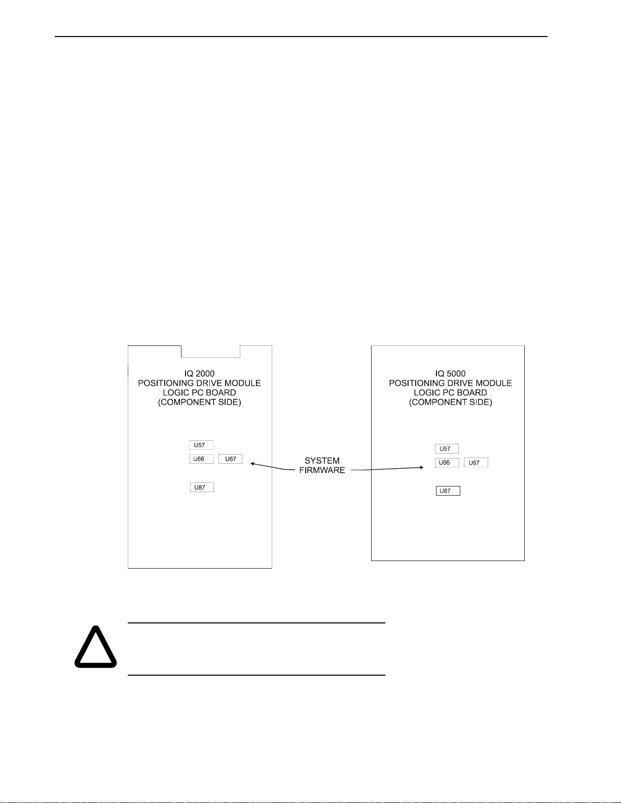
System Firmware Installation
All IQ 2000/5000 controllers come with the system firmware installed. Therefore, unless you
are upgrading your PDM to a newer version of firmware, you will not need to install system
firmware. Refer to Figure 2.2 for system firmware location.
FIGURE 2.2 Location of System Firmware
CAUTION: Do
power to the PDM is ON. Static electricity can damage the
!
P/N 0013-1027-005 Rev A
EPROMs. Wear a con ductive wrist strap whil e handling, or touch
earth ground before handling.
not
install or remove the fi rmware EPROMs while
Installing the Firmware EPROMs
1. Check that power to the PDM is OFF.
a. IQ-2000: Measur e voltage between PDM terminals m arked L1 an d L2/N (and L 3 on
PDM-75) to ensure incoming power is OFF. Also measure voltage between terminals marked L1 AUX and L2/N AUX if used, to ensure po wer is OFF. The green DC
BUS LED and the bicolor STATUS LED should be OFF.
b. IQ-5000: Measure voltages at Positive and Negative bus terminals to ensure incom-
ing power is OFF. If a PSM-AUX is used, measure the voltage at L1 and L2 of the
PSM-AUX to ensure that incoming power is OFF
2. Remove PDM cover.
3. Install the fo ur EPROMs on th e PDM logic boar d in s ockets U57, U66, U67 and U87. The
end of the EPROM with the notch must be toward the front of the PDM.
4. Install the PDM cover.
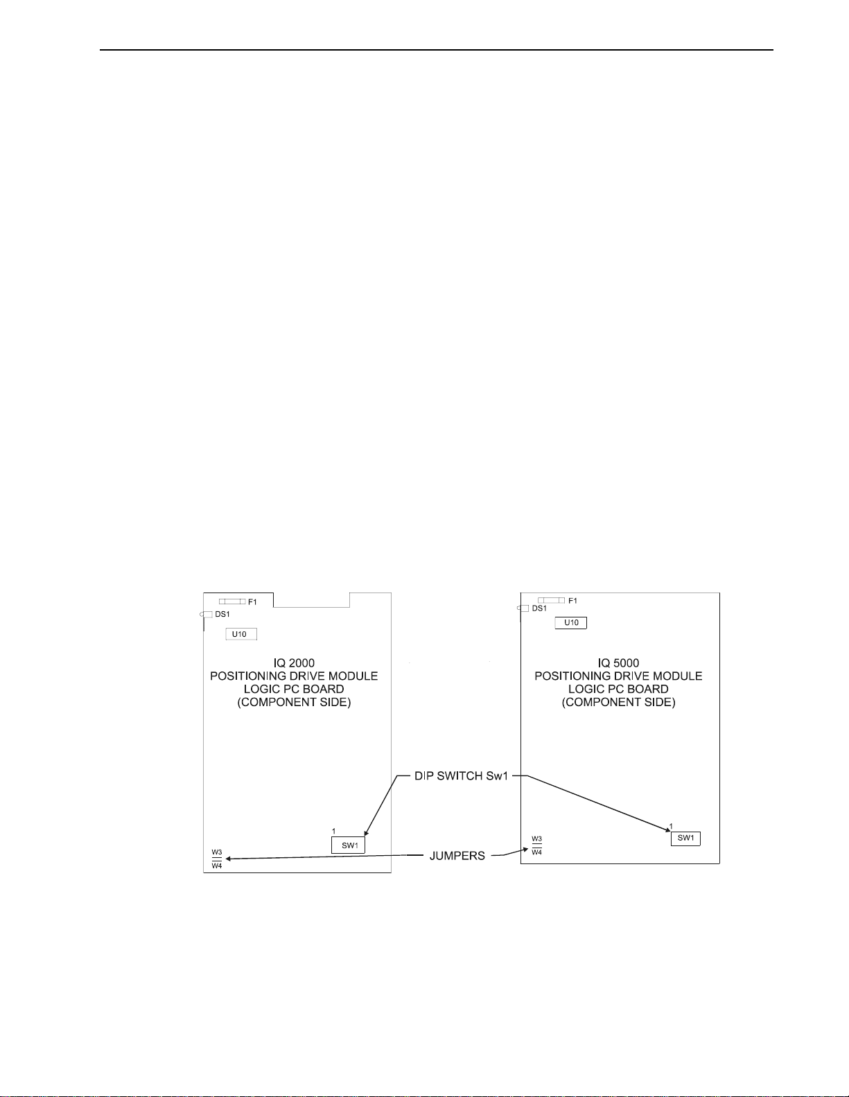
Jumper and DIP Switches
Jumpers W3 and W4 may be removed if an external 24 VDC power supply is used. Removing
these jumpers will disconnect the internal supply. The jumpers do not need to be removed if
only the 24 V common (P1 pin 1) is connected to m achine co mmon, but must be removed if an
external +24 VDC supply is connected to P2 pin 12.
Dip switch SW1 sets the address when multiple IQs are connected in multi-drop serial communications mode, and sets the mode of operation for the Operator Terminal serial port (port 1).
Refer to “Networking the IQ Operator Terminal” on page 3-20 for more information.
Refer to Figure 2.3 for the locations of jumpers W3, W4, and dip switch SW1 on the PDM logic
board.
Installation 2-5
FIGURE 2.3 Location of Jumper and DIP Switch
IQ 2000/5000 Installation Manual
2-6 Installation
D
C
Option Card Installation
Option cards should be installed before the PDM is mounted. Ensur e that power to the PDM is
OFF before installing.
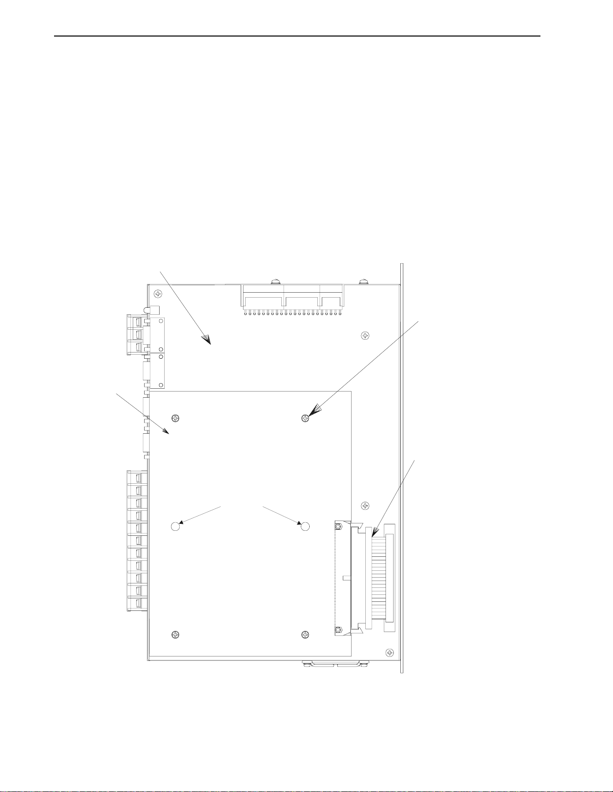
IQ-2000
Figure 2.4 illustrates the IQ-2000 option card. Follow these steps to install the card on the PDM
logic board:
1. Remove side cover by loosening the mounting screws and sliding cover off the unit.
2. Install option card B on IQ-2000 logic board C, using screws D. Six screws are provided
for mounting option cards on units built prior to J anuary 1995.
3. Install ribbon cable E between logic board and option card.
4. Install side cover back onto unit.
P10
P8
P9
111
B
not used
E
2
1
NOTE:
Mating connectors are provided with the option card for
customer connections to the option card connectors.
FIGURE 2.4 IQ-2000 Option Card Installation
P/N 0013-1027-005 Rev A
Installation 2-7
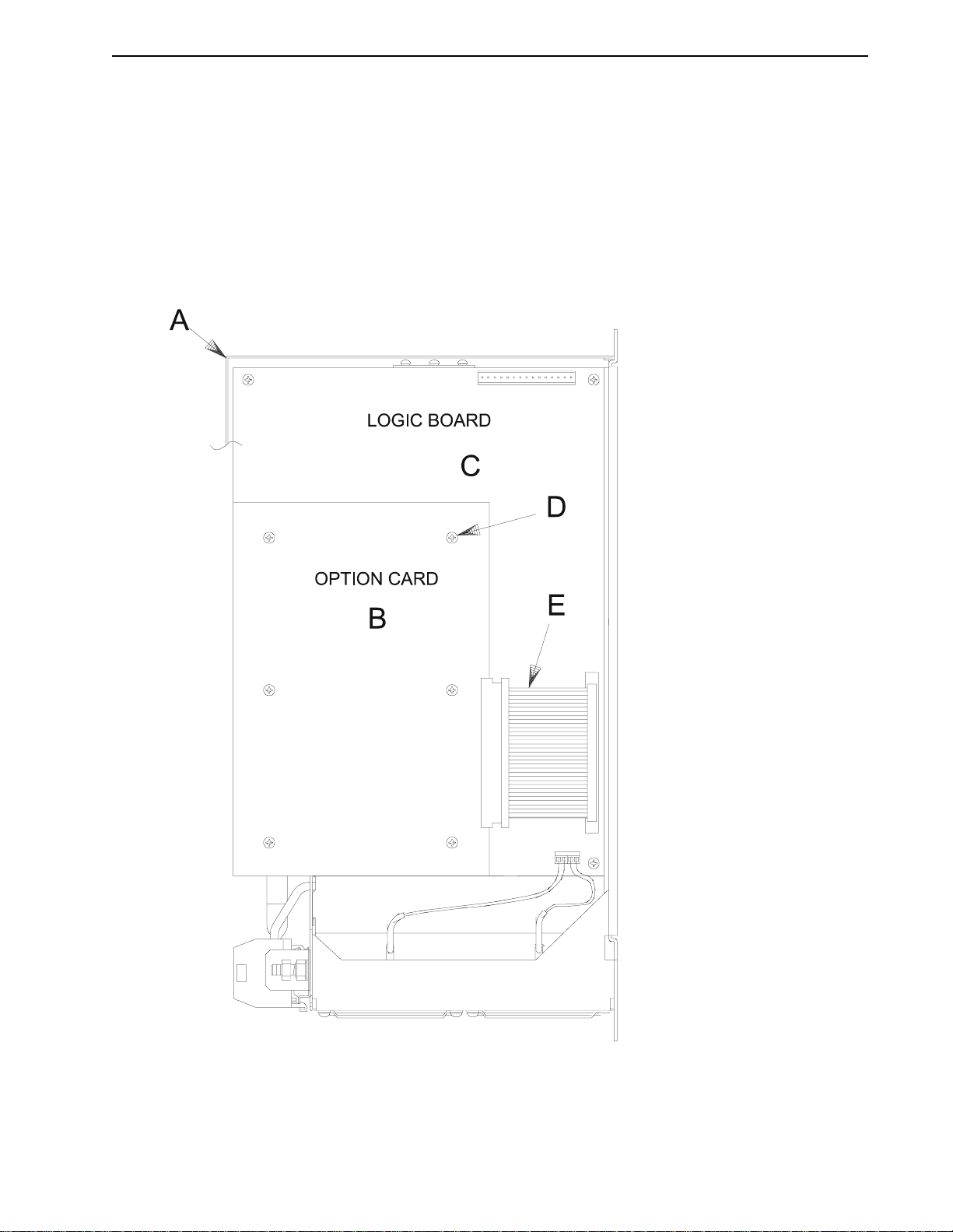
IQ-5000
Figure 2.5 illustrates the IQ-5000 option card. Follow these steps to install the card on the PDM
logic board:
1. Remove cover A from drive module. From inside the cover, remove the filler panel and
its two mounting nuts.
2. Install option card B onto IQ-5000 logic board C, using screws D.
3. Install ribbon cable E between logic board and option card.
4. Install cover A back onto drive module.
NOTE:
Mating connectors are provided with the option card for
customer connections to the option card connectors.
FIGURE 2.5 IQ-5000 Option Card Installation
IQ 2000/5000 Installation Manual

2-8 Installation
Mounting
Before mounting the PDM, any installation of option cards, Personality Modules, and system
firmware should be completed. Other opera tions such as r emoving jumpers on the logic boar d
should also be performed before mounting the system.
CAUTION: Complete all drilling, cutting, welding, etc., before
mounting the equipment. During installation, protect equipment
!
from metal chips, weld splatters and other debris. Failure to
observe this precautio n could resu lt in damage to or destruc tion
of the equi pment.
Environment
The PDM and power supply modules are designed for simple installation on a flat surface such
as the back wall or plate of an enclosur e. They mu st be enclosed in a gr ounded metal e nclosure
offering prot ection as defined in standard EN 60 529 (IEC 529) to at least IP54 such that they are
not accessible to an operator or unskilled person. A NEMA 12 enclosure exceeds these r equir ements providing protection to IP65. The environment in the enclosure must be clean and free
of oil mist, coolant mist, conductive particles, water and corrosive chemicals. The enclosure
must also be properly sized (and ventilated if required) to ensure that the maximum ambient
temperature of the PDM is not exceeded.
Ventilation
The maximum power losses are shown below to help in sizing an enclosure and any required
ventilation. Typical heat losses can run approximately one-half maximum power losses.
TABLE 2.2 Maximum Power Losses for IQ-Series Related Products
Model Maximum Loss (Watts)
PDM-10 50 + dissipative shunt
PDM-20 100 + dissipative shunt
PDM-25 120
PDM-30 150 + dissipative shunt
PDM-50 180
PDM-75 300 + dissipative shunt
PDM-100 275
PDM-150 300
PDM-150B 500 + dissipative shunt
PSM-50 110 + dissipative shunt
PSM-125 240 + dissipative shunt
Operator Terminal 25
3.0 kVA Transformer 350
TF-03 (3 kW transformer) 350
TF-06 (6 kW transformer) 600
TF-18 (18 kW transformer) 1200
As an additional aid in sizing an enclosure, with no active method of heat dissipation, the
following approximate equation is used:
T = 4.08 (Q/A) + 1.1,
Where T is temperature difference between inside air and outside ambient (°F), Q is heat generated in enclosure (Watts), and A is enclosure surface area (ft²).
The exterior surface of all six sides of an enclosure is calculated as
A = (2dw + 2dh + 2wh)/144
Where d (depth), w (width), and h (height) are in inches.
P/N 0013-1027-005 Rev A

Installation 2-9
TIP
TIP
Transformer Sizing
IQ 2000 and IQ 5000 systems do not require isolation transformers. A transformer may be
required, however, to match the voltage requirements of the contr oller to the available se rvice.
To size a transformer for an IQ 2000 or IQ 5000, the power output (KVA) of each axis must be
known. This can be derived by calculating the horsepower for each axis and converting that
horsepower into units f watts. If you are suppling power to more than one motor and drive,
simply add the KW ratings together from each calculation to get a system KW total.
Definitions:
KW = power or “real power”
KVA = apparent power
Transformer KVA rating = (Sum of average output power of each axis) x 2.0
Calculations are multiplied by a factor to compensate for the power and loss
elements within a power system. A factor of 2.0 is used with a single phase
system and a factor of 1.5 is used with a three phase system. This factor should
minimize the effects of the secondary line voltage sagging in the transformer
during peak current peri ods.
Intro
KVA
Speed RPM()Torque lb in–()×
---------------------------------------------------------------------------------- -
63 025,
746Watts
-------------------------
×
HP
KVA
--------------------------- -
× 2.0×=
1000Watts
If you are using t he Electro-C raft system siz ing program, Ea sySize™, the average speed and average torque data has already been calculated and can be
used in the above equation. If you are not sure of the exact speed and torque
in your application, another approach is to look at the speed/torque curve for
your drive/motor combination in the Electro-Craft catalog and use the values
for the worst case continuous speed and torque.
Sizing a transformer with an IQ-2000 PDM-30 drive and H-4075 motor:
Intro
3000RPM 75lb in–×
KVA
Transformer Size 5.3KVA=
NOTE:
The speed/torque curve information is based upon a drive module input voltage of 230 VAC. For a 115 VAC
input voltage, the maximum speed is reduced by half.
------------------------------------------------------ -
63 025,
746Watts
-------------------------
×
HP
KVA
--------------------------- -
× 2.0×=
1000Watts
Mounting Requirements
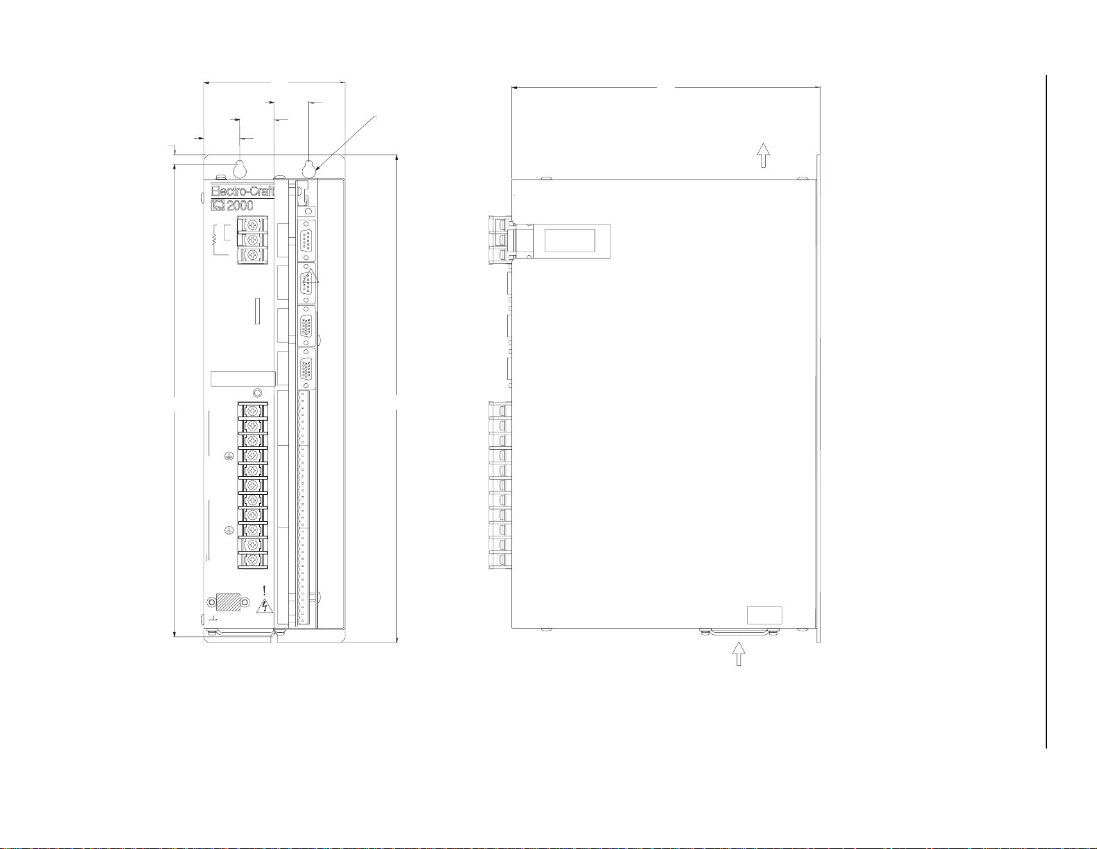
Position the PDM in a vertical position on a flat, solid surface that meets the mounting requirements for weight, humidity, and temperature listed in Chapter 6 , “Specifications.” The
following diagrams list dimensional mounting requirements.
IQ 2000/5000 Installation Manual
P/N 0013-1027-005 Rev A
[226.8]
AIR INTAKE
(
0.25
[6.4]
13.75
[349.3]
1
INTERNAL
2
EXTERNAL SHUNT
3
WARNI NG:
MAY EXIST U P TO FIVE MINUT ES
AFTER REMOVING POWER.
DC BUS
R
S
MOTOR
T
DC BUS+
DC BUS-
L1
L2/N
100-240 VAC 50/ 60 Hz
L1 AUX
L2/N AUX
1.05
[26.6]
TB2
HIGH VOLTAGE
TB1
4.10
[104.1]
STATUS
2-10 Installation
8.93
1.00
[25.4]
1.00
[25.4]
P7
SERIAL 1
AUXILIARY
P6
SERIAL 2
COMPUTER
P5
MOTOR
ENCODER 1
P4
ENCODER 2
AUXILIARY
P3
5
STATUS/ANALOG I/O
1
P2
10
DIGITAL INP UTS AN D OUT PUTS
5
1
P1
10
DIGITAL INPUTS
5
1
CLEARANCE HOLES FOR #10
(M5) MOUNTING SCREWS.
14.20
[360.6]
U10
AIR
EXHAUST
SW1
NOTES:
1. ALLOW 2.00 (50.8mm) CLEARANCE ABOVE & BELOW UNIT FOR AIR FLOW.
2. ALLOW 3.00
FIGURE 2.6 IQ-2000 PDM-10, PDM-20 and PDM-30 Mounting
76.5mm) CLEARANCE IN FRONT OF UNIT FOR CABLES.
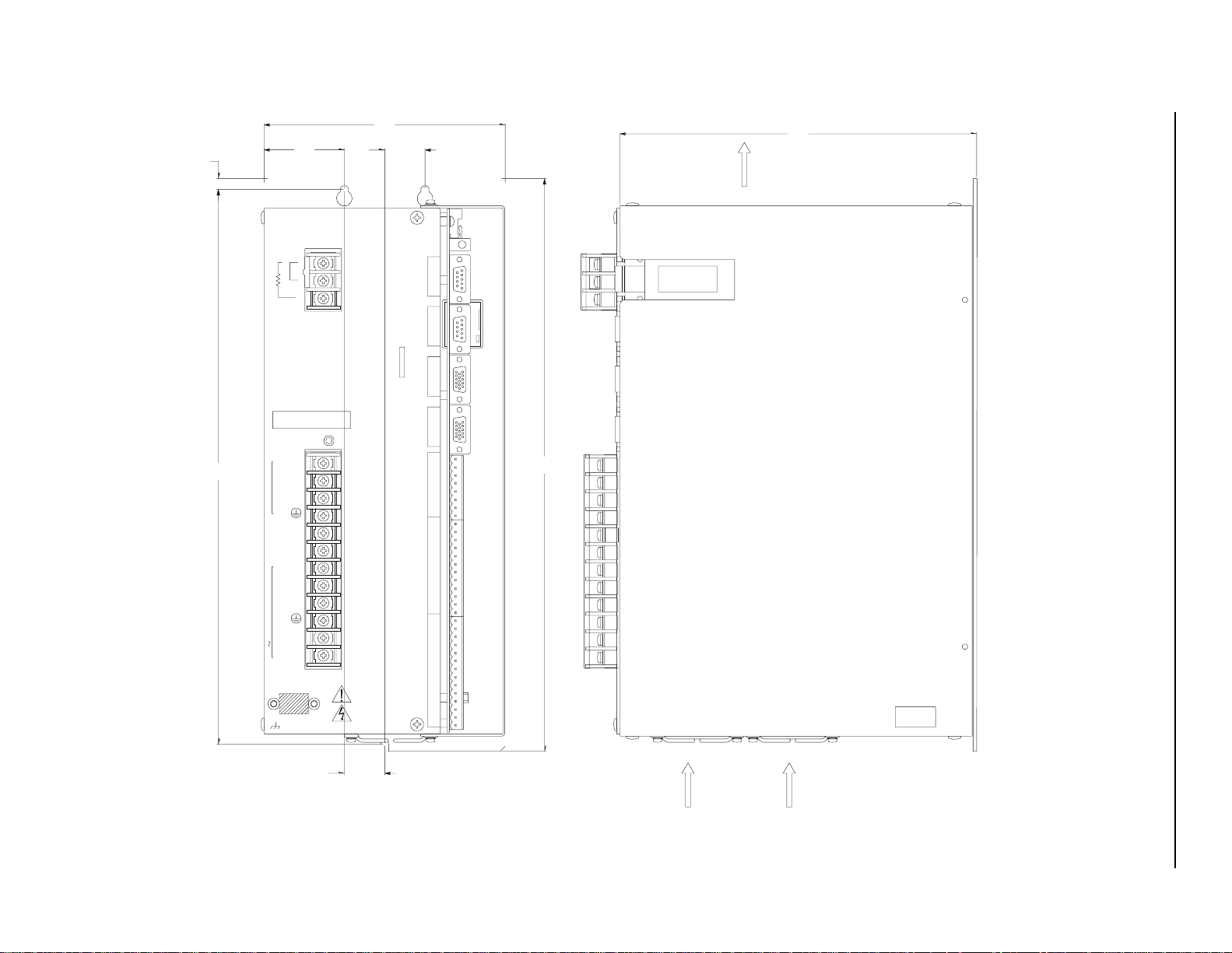
[224.5]
5.97
AIR EXHAUST
1.99
0.27
[7.0]
[50.5]
1
INTERNAL
2
EXTERNAL SHUNT
3
TB2
WARNING:
HIGH VOLTAGE
MAY EXIST UP TO EIGHT MINUTES
AFTER REMOVING P OW ER.
DC BUS
13.75
[349.3]
IQ 2000/5000 Installation Manual
R
S
MOTOR100-240 VAC 50/60 Hz
T
DC BUS+
DC BUS-
L1
L2/N
L3
L1 AUX
AUXL2/N
[151.7]
1.00
[25.4]
STATUS
P7
SERIAL 1
AUXILIARY
P6
SERIAL 2
COMPUTER
FINAL INSPECTION
P5
MOTOR
ENCODER 1
P4
ENCODER 2
AUXILIARY
P3
5
1
STATUS/ANALOG I/O
P2
10
5
DIGITAL INPUTS AND OUTPUTS
1
P1
10
14.20
[360.7]
U10
8.84
TB1
5
DIGITAL INPUTS
1
SW1
Installation 2-11
1.00
NOTES:
1. ALLOW 2.00 (50.8mm) CLEARANCE ABOVE & BELOW UNIT FOR AIR FLOW.
[25.4]
2. ALLOW 3.00 (76.5mm) CLEARANCE IN FRONT OF UNIT FOR CABLES.
FIGURE 2.7 IQ-2000 PDM-75 Mounting
AIR INTAKE
AIR INTAKE
P/N 0013-1027-005 Rev A
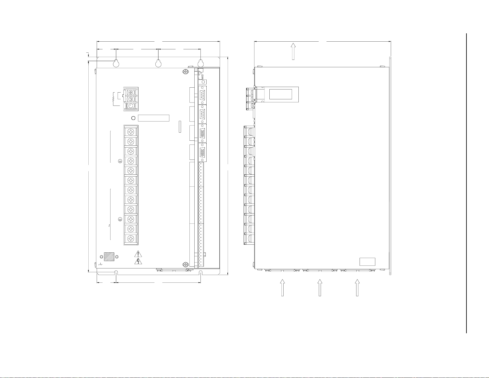
AIR INTAKE
AIR INTAKE
8.89
[7.0]
0.27
13.75
[349.3]
8.00
1.25
[31.8] [69.9] [69.9]
EXTERNAL SHUNT
MOTOR
DC BUS+
DC BUS-
100-240 VAC 50/60 Hz
L2/N AUX
2.75 2.75
1
INTERNAL
2
3
TB2
DC BUS
R
S
T
L1
L2
L3
L1 AUX
[203.2] [225.8]
HIGH VOLTAGE
WARNING:
MAY EXIST UP TO FIFTEEN MI NU TES
AFTER REMOVING POWER.
TB1
STATUS
2-12 Installation
AIR EXHAUST
P7
SERIAL 1
AUXILIARY
P6
SERIAL 2
COMPUTER
P5
MOTOR
ENCODER 1
P4
ENCODER 2
AUXILIARY
P3
5
STATUS/ANALOG I/O
1
P2
10
DIGITAL INPUTS AND OUTPUTS
5
1
P1
10
DIGITAL INPUTS
5
1
14.20
[360.7]
U10
SW1
1.25 5.50
NOTES:
1. ALLOW 2.00 (50.8mm) CLEARANCE ABOVE & BELOW UNIT FOR AIR FLOW.
[31.8] [139.7]
2. ALLOW 3.00 (76.5 mm) CLEARANCE IN FRONT OF UNIT FOR CA BLES.
FIGURE 2.8 IQ-2000 PDM-150B Mounting
AIR INTAKE
 Loading...