

Page 1
™
]
-45-37
A
n
]
z
0
g]
S
SPECIFICATIONS
PECIFICATION
Wingspan:
Wingspan:
26.5 in
.5 i
[675mm]
675mm
Wing Area: 153 in
[9.9 dm2]
2
Weight:
Weight
Wing
Loading:
28–30 oz
28–30 o
[790– 850 g]
–
50
26.4– 28.2 oz/ft
[81–86 g/dm2]
WARRANTY
Great Planes® Model Manufacturing Co. guarantees this kit to
be free from defects in both material and workmanship at the
date of purchase. This warranty does not cover any component
parts damaged by use or modification. In no case shall Great
Planes’ liability exceed the original cost of the purchased kit.
Further, Great Planes reserves the right to change or modify this
warranty without notice.
In that Great Planes has no control over the final assembly or
material used for final assembly, no liability shall be assumed nor
accepted for any damage resulting from the use by the user of
the final user-assembled product. By the act of using the
user-assembled product, the user accepts all resulting liability.
If the buyer is not prepared to accept the liability associated
with the use of this product, the buyer is advised to return
INSTRUCTION MANUAL
Length: 30.5 in [775mm]
ength:30.5 in [775mm
Radio: 3-Channel, two micro servos,
io:3-Channel, two micro servos,
mini Rx
ni Rx
™
Motor,
2
otor,
ESC
24-45-3790kV Ammo
35A ESC, HyperFlow
56mm fan
this kit immediately in new and unused condition to the
place of purchase.
To make a warranty claim send the defective part or item to
Hobby Services at the address below:
Hobby Services
3002 N. Apollo Dr. Suite 1
Champaign IL 61822 USA
Include a letter stating your name, return shipping address, as
much contact information as possible (daytime telephone
number, fax number, e-mail address), a detailed description of
the problem and a photocopy of the purchase receipt. Upon
receipt of the package the problem will be evaluated as quickly
as possible.
,
™
READ THROUGH THIS MANUAL BEFORE STARTING CONSTRUCTION. IT CONTAINS IMPORTANT
INSTRUCTIONS AND WARNINGS CONCERNING THE ASSEMBLY AND USE OF THIS MODEL.
Entire Contents © Copyright 2010 GPMA1800 Mnl
Champaign, Illinois
(217) 398-8970, Ext 5
airsupport@greatplanes.com
Page 2
TABLE OF CONTENTS
INTRODUCTION . . . . . . . . . . . . . . . . . . . . . . . . . . . . . . . .2
SAFETY PRECAUTIONS . . . . . . . . . . . . . . . . . . . . . . . . .2
DECISIONS YOU MUST MAKE. . . . . . . . . . . . . . . . . . . . .3
Battery and ESC . . . . . . . . . . . . . . . . . . . . . . . . . . . . .3
Servos, Receiver . . . . . . . . . . . . . . . . . . . . . . . . . . . . .3
ADDITIONAL ITEMS REQUIRED . . . . . . . . . . . . . . . . . . .3
Battery Chargers . . . . . . . . . . . . . . . . . . . . . . . . . . . . .3
Adhesives and Building Supplies . . . . . . . . . . . . . . . .4
IMPORTANT BUILDING NOTES. . . . . . . . . . . . . . . . . . . .4
KIT INSPECTION. . . . . . . . . . . . . . . . . . . . . . . . . . . . . . . .4
ORDERING REPLACEMENT PARTS . . . . . . . . . . . . . . . .4
KIT CONTENTS. . . . . . . . . . . . . . . . . . . . . . . . . . . . . . . . .5
ASSEMBLY INSTRUCTIONS . . . . . . . . . . . . . . . . . . . . . .6
Assemble the Stand. . . . . . . . . . . . . . . . . . . . . . . . . . .6
Prepare the HyperFlow Fan Unit . . . . . . . . . . . . . . . . .6
Install the Fan Unit . . . . . . . . . . . . . . . . . . . . . . . . . . . .9
ASSEMBLE THE WING . . . . . . . . . . . . . . . . . . . . . . . . . .10
Mount the Wing . . . . . . . . . . . . . . . . . . . . . . . . . . . . .10
Hook up the Ailerons . . . . . . . . . . . . . . . . . . . . . . . . . 11
Mount the Horizontal Stabilizer (Stab) . . . . . . . . . . . . 11
Install the Elevators . . . . . . . . . . . . . . . . . . . . . . . . . .12
Hook up the Elevators . . . . . . . . . . . . . . . . . . . . . . . .14
FINAL ASSEMBLY . . . . . . . . . . . . . . . . . . . . . . . . . . . . .14
Mount the Receiver and Battery . . . . . . . . . . . . . . . .14
Attach the Landing Skids . . . . . . . . . . . . . . . . . . . . . .16
Apply the Hand Grips. . . . . . . . . . . . . . . . . . . . . . . . . 17
Apply the Decals . . . . . . . . . . . . . . . . . . . . . . . . . . . .17
GET THE MODEL READY TO FLY . . . . . . . . . . . . . . . . .18
Set the Control Throws. . . . . . . . . . . . . . . . . . . . . . . .18
Balance the Model (C.G.). . . . . . . . . . . . . . . . . . . . . .18
Balance the Model Laterally. . . . . . . . . . . . . . . . . . . .19
PREFLIGHT . . . . . . . . . . . . . . . . . . . . . . . . . . . . . . . . . . .19
Identify Your Model. . . . . . . . . . . . . . . . . . . . . . . . . . .19
Charge the Batteries . . . . . . . . . . . . . . . . . . . . . . . . .19
Break In the Motor . . . . . . . . . . . . . . . . . . . . . . . . . . .19
Run the Motor . . . . . . . . . . . . . . . . . . . . . . . . . . . . . .19
Assemble the Bungee Launch . . . . . . . . . . . . . . . . . .20
CHECKLIST. . . . . . . . . . . . . . . . . . . . . . . . . . . . . . . . . . . 21
FLYING. . . . . . . . . . . . . . . . . . . . . . . . . . . . . . . . . . . . . . .21
Mount the Wing . . . . . . . . . . . . . . . . . . . . . . . . . . . . .22
Ground Check and Range Check . . . . . . . . . . . . . . .22
Takeoff . . . . . . . . . . . . . . . . . . . . . . . . . . . . . . . . . . . .22
Hand-launch. . . . . . . . . . . . . . . . . . . . . . . . . . . . . . . .22
Bungee-launch. . . . . . . . . . . . . . . . . . . . . . . . . . . . . .23
Flying . . . . . . . . . . . . . . . . . . . . . . . . . . . . . Back Cover
Landing . . . . . . . . . . . . . . . . . . . . . . . . . . . Back Cover
INTRODUCTION
Thank you for purchasing the ElectriFly Evader EDF (electric
ducted fan) ARF. Prepare to be thrilled! Before you fl y your
Evader make sure you’re ready; get a good night’s sleep
and make sure your vision is good. If you don’t bring your
“A-game,” the Evader’s small size and extreme speed will
cause it to get out of visual range within a few seconds.
We’ve clocked it at average speeds of 105mph [170kph], but
it seems like it’s going at least 200mph [320kph]! The Evader
does fl y predictably and smoothly, so TOC (Tournament of
Champions) skills are not required, but you still should be a
competent pilot. And even after you get used to your Evader,
you’ll still breathe a sigh of relief after every landing (but
you’ll quickly become addicted to the speed and be ready for
the next fl ight as soon as you catch your breath).
For the latest technical updates or manual corrections to the
Evader visit the Great Planes web site at www.greatplanes.
com. Open the “Airplanes” link, then select “Evader ARF”. If
there is new technical information or changes to this model
a “tech notice” box will appear in the upper left corner of
the page.
AMA
If you are not already a member of the AMA, please join! The
AMA is the governing body of model aviation and membership
provides liability insurance coverage, protects modelers’
rights and interests and is required to fl y at most R/C sites.
ACADEMY OF MODEL AERONAUTICS
5151 East Memorial Drive
Muncie, IN 47302-9252
Tele. (800) 435-9262
Fax (765) 741-0057
Or via the Internet at:
http://www.modelaircraft.org
IMPORTANT!!!
Two of the most important things you can do to preserve the
radio controlled aircraft hobby are to avoid fl ying near full-
scale aircraft and avoid fl ying near or over groups of people.
PROTECT YOUR MODEL, YOURSELF
& OTHERS… FOLLOW THESE
IMPORTANT SAFETY PRECAUTIONS
1. Your Evader should not be considered a toy, but rather a
sophisticated, working model that functions very much like
a full-size airplane. Because of its performance capabilities,
the Evader, if not assembled and operated correctly, could
possibly cause injury to yourself or spectators and damage
to property.
2. You must assemble the model according to the
instructions. Do not alter or modify the model, as doing so
may result in an unsafe or unfl yable model. In a few cases
the instructions may differ slightly from the photos. In those
instances the written instructions should be considered
as correct.
3. You must take time to build straight, true and strong.
4. You must use an R/C radio system that is in good condition,
a correctly sized motor, and other components as specifi ed
in this instruction manual. All components must be correctly
2
Page 3
installed so that the model operates correctly on the ground
and in the air. You must check the operation of the model and
all components before every fl ight.
5. If you are not an experienced pilot or have not fl own
this type of model before, we recommend that you get
the assistance of an experienced pilot in your R/C club for
your fi rst fl ights. If you’re not a member of a club, your local
hobby shop has information about clubs in your area whose
membership includes experienced pilots.
6. While this kit has been fl ight tested to exceed normal use,
if the plane will be used for extremely high stress fl ying, such
as racing, or if a motor larger than one in the recommended
range is used, the modeler is responsible for taking steps to
reinforce the high stress points and/or substituting hardware
more suitable for the increased stress.
7. WARNING: The fuselage and tail cone adapter included in
this kit are made of fi berglass, the fi bers of which may cause
eye, skin and respiratory tract irritation. Never blow into a
part to remove fi berglass dust, as the dust will blow back into
your eyes. Always wear safety goggles, a particle mask and
rubber gloves when grinding, drilling and sanding fi berglass
parts. Vacuum the parts and the work area thoroughly after
working with fi berglass parts.
We, as the kit manufacturer, provide you with a top quality,
thoroughly tested kit and instructions, but ultimately the
quality and fl yability of your fi nished model depends
on how you build it; therefore, we cannot in any way
guarantee the performance of your completed model,
and no representations are expressed or implied as to the
performance or safety of your completed model.
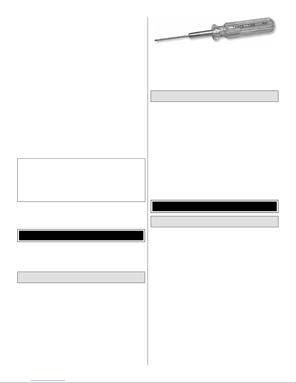
Note: A precision 1.5mm Allen wrench will be required
for tightening the set screws in the brass fan adapter. Do
not attempt to use a worn out wrench; you may strip out
the wrench or set screws, making it impossible to securely
tighten or remove them for replacement. The 1.5mm MIP
Thorp Hex Driver (MIPR9007) is recommended.
Servos and Receiver
No unusual radio gear is required for the Evader, just a small
receiver and one elevator servo and one aileron servo in the
20 oz-in torque range.
• Suitable servo choices (in order of preference) for Futaba
servos include S3156 (digital, metal gear, high-torque–
FUTM0656), S3153MG (digital, metal gear–FUTM0652),
S3153 (digital–FUTM0653), S3117 (high-torque–
FUTM0417) and S3107 (standard micro–FUTM0025).
• Any mini 4-channel aircraft receiver will work. In the
prototypes a Futaba 2.4GHz R617FS FASST
(FUTL7627) was used.
™
receiver
®
Remember: Take your time and follow the instructions to
end up with a well-built model that is straight and true.
DECISIONS YOU MUST MAKE
This is a partial list of items required to fi nish the Evader
that may require planning or decision making before starting
assembly. Order numbers are provided in parentheses.
Battery and ESC
• The Evader was designed for and comes equipped with
the Great Planes ElectriFly HyperFlow 56mm ducted fan
system (GPMG3910) and the Great Planes ElectriFly 24-
45-3790kV Ammo inrunner brushless motor (GPMG5185).
These components drop right in with no modifi cation.
• The recommended battery is the Great Planes ElectriFly
14.8V (4S) 2200mAh 25C LiPo (GPMP0521). Under “normal”
fl ying conditions (mostly full throttle), this provides average
fl ight times of approximately 4 minutes with approximately
one more minute of motor run time for additional landing
attempts.
• The Great Planes ElectriFly SS-35 35 Amp brushless ESC
(GPMM1830) is also recommended.
ADDITIONAL ITEMS REQUIRED
Battery Chargers
• A LiPo-capable battery charger and a power source for the
battery charger is required. One recommended charger
is the Great Planes ElectriFly TritonEQ™ AC/DC Charger
(GPMM3155). The Triton EQ can be powered either by an
AC or DC power source and features a built-in LiPo cell
balancer.
• Another suitable LiPo battery charger is the Great Planes
PolyCharge4
PolyCharge4 can charge up to four LiPo batteries at the
same time, but requires separate LiPo cell balancers, so
for each LiPo battery you wish to charge simultaneously
(up to 4), one Great Planes Equinox™ LiPo Cell Balancer
(GPMM3160) will be required. Additionally, the Equinox
comes with 2S and 3S charge adapters, so a 4S charge
adapter (GPMM3162) must also be purchased separately.
Finally, the PolyCharge4 does not have AC capability, so
if wall-charging from home is a priority a separate A/C
12-Volt power source must also be purchased. A suitable
power supply then for the PolyCharge4 is the Great Planes
12V 12A DC power supply (GPMP0901).
3
™
DC LiPo charger (GPMM3015). The
Page 4
Adhesives and Building Supplies
LITHIUM BATTERY HANDLING & USAGE
Other than common hobby tools this is the list of adhesives
and Building Supplies that are required to fi nish the Evader.
1/2 oz. [15g] Thin Pro™ CA (GPMR6001)
❏
1/2 oz. [15g] Medium Pro CA+ (GPMR6007)
❏
CA applicator tips (HCAR3780)
❏
Pro 30-minute epoxy (GPMR6047)
❏
1/16" [1.6mm] drill bit
❏
#1 Hobby knife (XACR3511)
❏
#11 blades (5-pack, XACR2911)
❏
2 oz. [57g] spray CA activator (GPMR6035)
❏
CA debonder (GPMR6039)
❏
Denatured alcohol (for epoxy clean up)
❏
Threadlocker thread locking cement (GPMR6060)
❏
Stick-on segmented lead weights (GPMQ4485)
❏
Great Planes 1/8" x 3/8" [3.2 x 9.5mm] single-sided
❏
adhesive foam tape (GPMQ4224) (Optional, for plywood
stand)
IMPORTANT BUILDING NOTES
The wing and horizontal stabilizer of the Evader are factory-
covered with Top Flite® MonoKote® fi lm. Should repairs ever be
required, MonoKote can be patched with additional MonoKote
purchased separately. MonoKote is packaged in six-foot rolls,
but some hobby shops also sell it by the foot. If only a small
piece of MonoKote is needed for a minor patch, perhaps a
fellow modeler would give you some. MonoKote is applied
with a model airplane covering iron, but in an emergency a
regular iron could be used. A roll of MonoKote includes full
instructions for application. Following are the colors used on
this model and order numbers for six foot rolls.
White (TOPQ0204)
Orange (TOPQ0202)
Black (TOPQ0208)
WARNING!! Read the entire instruction sheet included with
your battery. Failure to follow all instructions could cause
permanent damage to the battery and its surroundings, and
cause bodily harm!
• ONLY use a LiPo approved charger. NEVER use a
NiCd/NiMH peak charger.
• NEVER charge in excess of 4.20V per cell.
• ONLY charge through the “charge” lead. NEVER
charge through the “discharge” lead.
• NEVER charge at currents greater than 1C.
• ALWAYS set the charger’s output volts to match
the battery volts.
• ALWAYS charge in a fi reproof location.
• NEVER trickle charge.
• NEVER allow the battery temperature to exceed
150° F (65° C).
• NEVER disassemble or modify the pack wiring in
any way or puncture the cells.
• NEVER discharge below 2.5V per cell.
• NEVER place the battery or charger on
combustible materials or leave it unattended during
charge or discharge.
• ALWAYS KEEP OUT OF THE REACH OF
CHILDREN.
• NEVER charge the battery in the plane.
• ALWAYS remove the battery from the plane after
a crash. Set it aside in a safe location for at least
20 minutes. If the battery is damaged in the crash it
could catch fi re.
If the battery starts to swell, quickly move the battery to a safe
location, preferably outside: Place it in a bucket, covering the
battery with sand.
The stabilizer and wing incidences and motor thrust angles
have been factory-built into this model. However, some
technically-minded modelers may wish to check these
measurements anyway. To view this information visit the web
site at www.greatplanes.com and click on “Technical Data.”
Due to manufacturing tolerances which will have little or no
effect on the way your model will fl y, please expect slight
deviations between your model and the published values.
KIT INSPECTION
Before starting to build, inspect the parts to make sure
they are of acceptable quality. If any parts are missing or
are not of acceptable quality, or if you need assistance
with assembly, contact Product Support. When reporting
defective or missing parts, use the part names exactly as
they are written in the Kit Contents list.
Great Planes Product Support
3002 N. Apollo Drive, Suite 1
Champaign, IL 61822
Telephone: (217) 398-8970, ext. 5
Fax: (217) 398-7721
E-mail: airsupport@greatplanes.com
4
Page 5
ORDERING REPLACEMENT PARTS
REPLACEMENT PARTS LIST
Replacement parts for the Great Planes Evader ARF are
available using the order numbers in the Replacement Parts
List that follows. The fastest, most economical service can
be provided by your hobby dealer or mail-order company.
To locate a hobby dealer, visit the Great Planes web site
at www.greatplanes.com. Choose “Where to Buy” at the
bottom of the menu on the left side of the page. Follow the
instructions provided on the page to locate a U.S., Canadian
or International dealer.
Parts may also be ordered directly from Hobby Services
by calling (217) 398-0007, or fax at (217) 398-7721, but full
retail prices and shipping and handling charges will apply.
Illinois and Nevada residents will also be charged sales tax.
®
If ordering via fax, include a Visa
or MasterCard® number
and expiration date for payment.
Mail parts orders and payments by personal check to:
Hobby Services
3002 N. Apollo Drive, Suite 1
Champaign, IL 61822
Be certain to specify the order number exactly as listed in
the Replacement Parts List. Payment by credit card or
personal check only; no C.O.D.
If additional assistance is required for any reason, contact
Product Support by telephone at (217) 398-8970, or by
e-mail at productsupport@greatplanes.com.
Order No. Description
GPMA2881
GPMA2882
GPMA2883
GPMA2884
GPMA2885
GPMA2886
GPMA2887
GPMA2888
GPMG3910
GPMG5185
Wing Set
Horizontal Stabilizer Set
Canopy/Hatch Set
Fuselage Set
Bungee Launch Set
Decal
Wing and Tail Skids
Bungee Hook/Nut/Washer
HyperFlow Fan
Ammo (24-45-3790 kV) Brushless Motor
Full-size plans are not available.
NOTE
You can download a copy of this
manual at www.greatplanes.com.
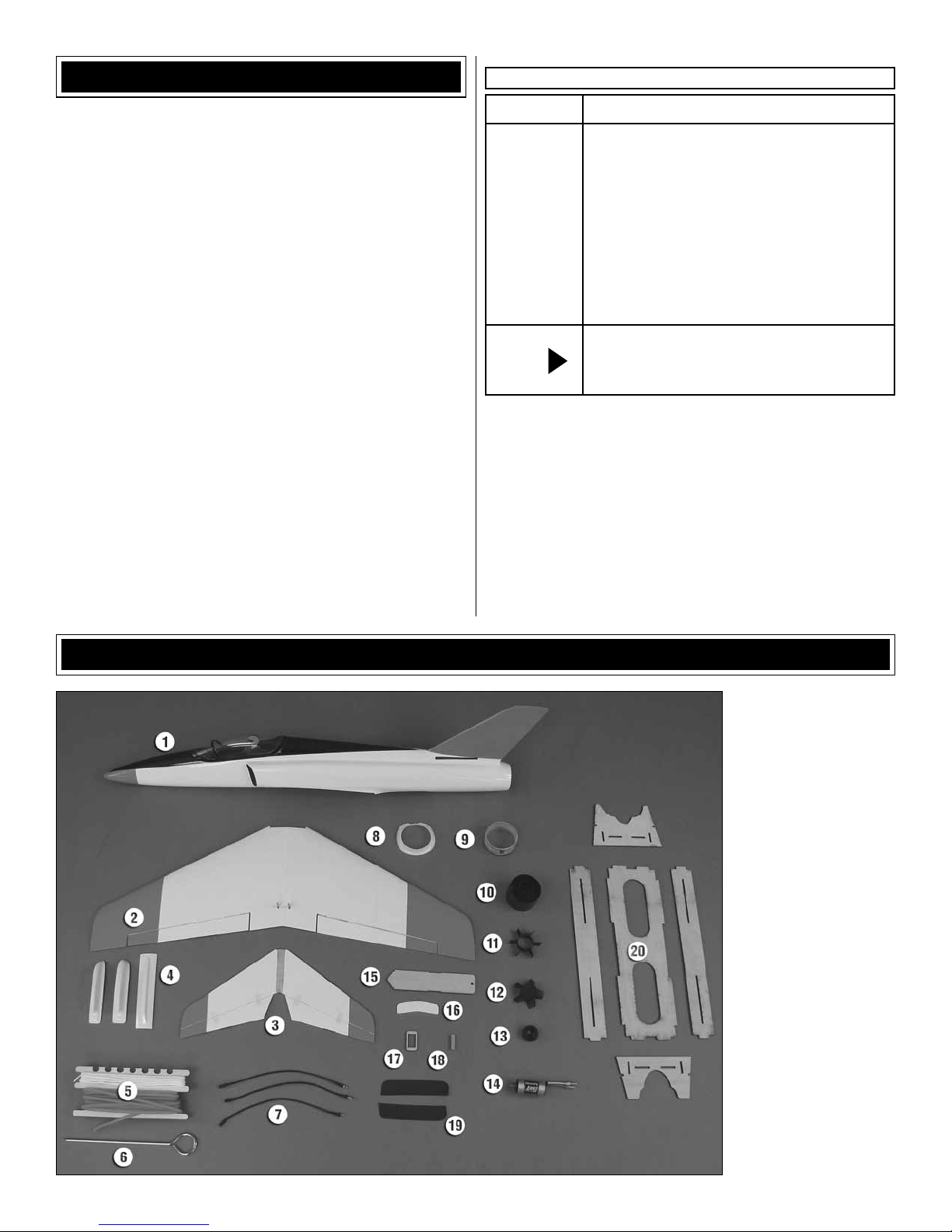
KIT CONTENTS
1. Fuselage, canopy hatch
2. Wing
3. Horizontal stabilizer
(stab) with elevators
4. Wing skids, tail skid
5. Bungee launch cord,
tubing, winder
6. Bungee launch stake
7. ESC motor extension
wires
8. Front housing fl ange
9. Cone adapter
10. Fan housing
11. Stator extension
12. Fan rotor
13. Rotor cone
14. Ammo inrunner motor
15. External battery plate
16. Wing bolt plate
17. Aileron servo mount plate
18. Wing dowel
19. Hand grips
20. Assembly/transport stand
5
Page 6
MOTOR & FAN INSTALLATION
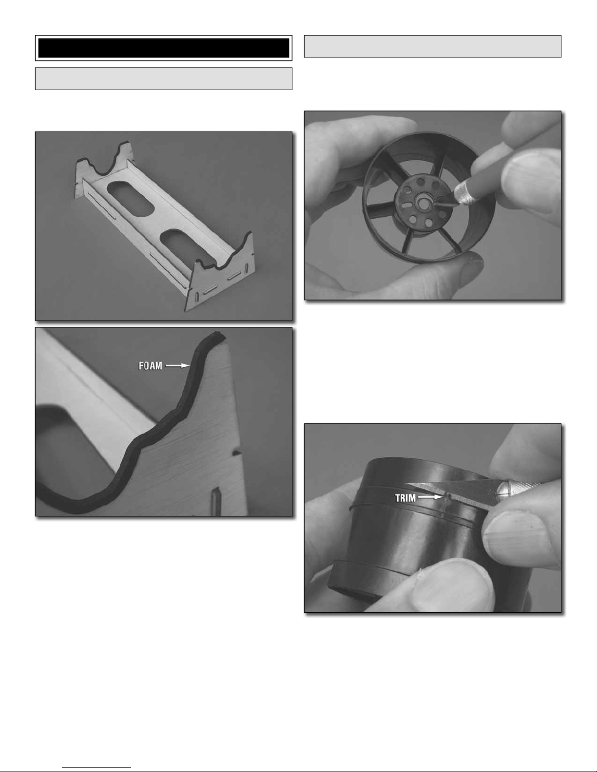
Assemble the Stand
The included assembly/transport stand holds your Evader
upside-down or upright.
Prepare the HyperFlow Fan Unit
1. Review steps 1 through 6 for Installing a Brushless
❏
Motor on pages 6 and 7 of the separate HyperFlow instruction
manual, but don’t perform any of the steps yet.
2. Enlarge the hole in the fan housing as shown. Once the
❏
fan unit and motor have been installed in the fuselage, this
will allow removal of the motor without having to remove the
brass fan adapter.
Test-fi t, then glue together the plywood parts of the stand.
The stand may be used as-is, or you could add foam tape
cut into 1/8" x 9" [3.2 x 230mm] strips. The foam will adhere
best if you fi rst sand the edges of the stand, then seal with
medium CA before applying the foam.
3. As shown in the HyperFlow manual, trim the three
❏
alignment guides from inside the fan housing. (Also as
noted in the HyperFlow manual, a rotary tool with a sanding
drum make this easier.)
4. Trim any fl ashing from around the fan housing so the
❏
fi berglass cone adapter will fi t well.
6
Page 7
FAN ROTOR
S
O
ADAPTER
(BRASS)
MOTOR
SHAFT
NO
The adapter is
not all the way on.
YES
T
P
FLAT
The adapter is
all the way
down onto the
motor shaft up
to the threads.
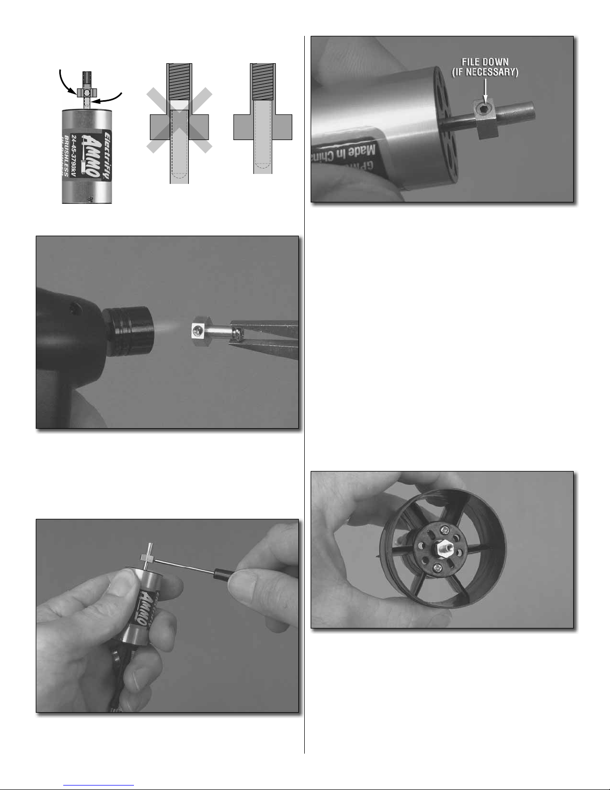
7. Test fi t only the fan rotor to the rotor adapter. If the head
❏
of the set screw opposite the fl at spot is protruding from the
adapter and making it diffi cult to install the fan rotor, cover
the front of the motor with a cloth or paper towel and use a
metal fi le to fi le down the screw so the fan will fi t properly.
8. Test mount the fan rotor to the adapter with the rotor
❏
cone, the 3mm Phillips screw and the 3mm washer that
came with the fan unit—the HyperFlow instructions specify
using a 3mm x 8mm screw, but the 3 x 5mm screw included
with the fan may be used.
5. Press the brass fan rotor adapter onto the motor
❏
shaft—make sure one of the set screw holes in the adapter
is aligned with the fl at spot on the shaft and make certain the
adapter goes on all the way up to the threads. If you can’t get
the adapter to go all the way, use a hobby torch to heat the
adapter fi rst. Then, slide it into the shaft.
Hint: For optimal performance it is desirable for the fan rotor
to turn as concentrically (“true”) as possible. Test fi t the rotor
in different orientations around the adapter spinning it by
hand each time. When you fi nd the orientation that is the
truest, use a hobby knife to lightly scratch a small “X” at the
base of the rotor where it aligns with the fl at spot on the motor.
When you mount the rotor later, do so in this orientation.
9. Remove the cone and rotor and set them aside.
❏
10. Mount the motor to the fan housing–you can use the
❏
3 x 5mm screws included with the Ammo motor (and a drop
of threadlocker on the threads). Any set of holes in the fan
housing that align with the holes in the motor may be used,
but we used the outer holes in the motor. Use care not to
overtighten the screws so much that you damage the plastic.
6. Add a small drop of threadlocker to the threads on the
❏
set screws for the adapter. Then, use a quality 1.5mm Allen
wrench to tighten set screws.
11. Glue the stator extension to the fan housing as shown
❏
in the HyperFlow manual. Make sure the little notches in the
stator fi t around the housing.
7
Page 8
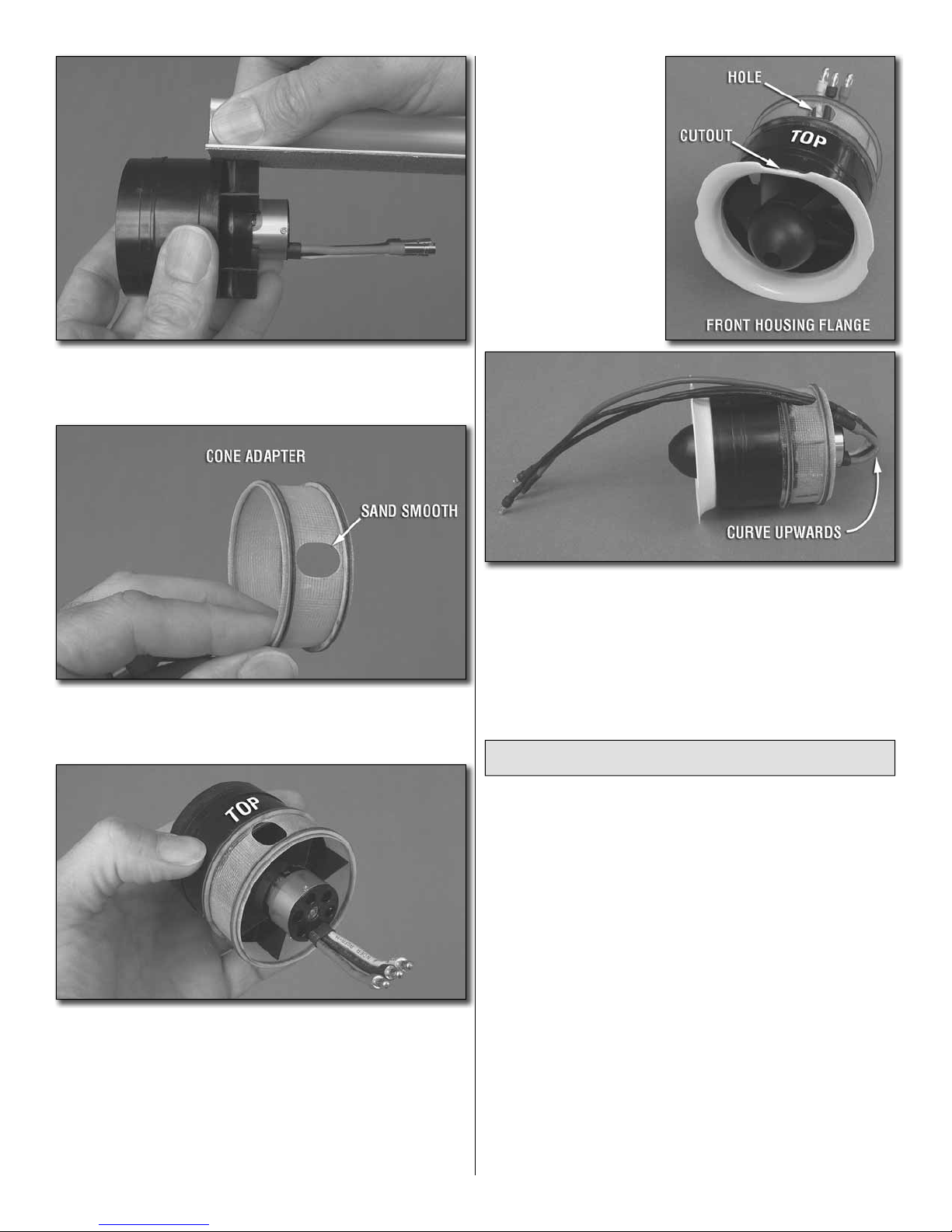
12. Lightly sand the edge of each blade on the stator
❏
extension to remove any fl ashing and to make sure they are
even with the fan housing.
15. Fit, then use thin
❏
CA to glue the included
vacuum-formed front
housing fl ange into the
front of the fan unit. Make
sure the cutout for the
motor wires is also on the
top of the unit (aligned
with the wire hole in the
cone adapter).
13. Use medium-grit sandpaper to smooth the rough
❏
edges around the motor wire hole in the fi berglass tail cone
adapter so it won’t damage the motor wires.
14. Test fi t but do not glue the cone adapter to the rear of the
❏
fan housing. Note that the hole in the housing should be 180°
from the side of the motor where the wires exit—this will be the
top of the unit. Once you have the housing and adapter mated
correctly, permanently glue the two together by adding a few
drops of thin CA to the seam around the outside. Also apply a
few drops of medium CA to each stator blade where it contacts
the inside of the adapter. Note: Apply the CA sparingly and
with care. Otherwise it will run all over the place.
16. Curve the motor wires upward toward the hole in the
❏
top of the cone adapter. Then guide the included motor wire
extensions through the hole and connect them to the motor.
17. Install the fan rotor onto the motor noting the orientation
❏
you marked earlier (for minimal run out)—be certain to use a
small drop of threadlocker on the 3mm screw.
Test Run the Motor/Fan Unit
1. You may perform either a brief test-run of the motor/fan
❏
unit, or do the complete break-in procedure as described on
the back cover of the HyperFlow instruction manual. In either
case prepare to run the motor by connecting the ESC to
your receiver and to the motor wires coming from the motor.
Reverse the throttle channel in your transmitter and turn on
the transmitter. Connect your motor battery to the ESC.
2. Follow all the precautions and run the motor at no more
❏
than 1/4 throttle as described by the “PREPARE TO RUN
THE FAN” instructions on the back cover of the HyperFlow
fan instructions. (If the motor is turning backwards switch any
two of the motor wires with each other.) Check for vibration
and/or unusual noises and do not proceed until resolving
any problems.
3. Continue with the rest of the break-in procedure until
❏
the system is fully broken-in, or if you’re satisfi ed with the
way the unit is performing stop now and mount the unit in
the fuselage as described in the next section. Be certain to
complete the break-in procedure before fl ying your Evader
for the fi rst time.
8
Page 9

Install the Fan Unit
The fan unit is easy to install, but it takes a little fi nagling
to get it through the intake hole. It’s a good idea to test fi t
the fan without glue so you can make sure it fi ts properly.
Once permanently installed, the fan unit will not be possible
to remove. However, the motor may be removed by taking
off the fan rotor, unscrewing the motor mounting screws and
taking the motor out the back through the tail cone. Once
the motor is out of the tail cone, the motor wires can be
disconnected. If you can’t get a good enough grip with your
fi ngers to pull the fan rotor off the adapter, make a rotor
puller from an 8-1/2" [215mm] piece of 2-56 pushrod wire
by bending it as shown. Insert the short hooks on the ends
of the puller under the fan hub and pull.
1" [25mm]
3-1/2" [90mm]
ROTOR PULLER
1/4" [6mm]
2. Rotate the fan unit until the motor wire cutout is centered
❏
in the top of the fuselage just under the fi n. The motor wires
should also be in the top of the fuselage as shown.
3. Guide the fan unit aft until the cone adapter mates with
❏
the tail cone already in the fuselage and the front housing
fl ange is just aft of the opening. Note that the cone adapter
should key around the inside of the front of the tail cone.
1. With the fan unit on its side (so the wire cutout in
❏
the housing fl ange will straddle the edge of the fuselage
opening), drop the rear, then the front of the unit down into
the fuselage.
4. Now that you’ve confi rmed how the fan unit fi ts, remove
❏
it from the fuselage. Apply a bead of 30-minute epoxy mixed
with microballoons fi ller (or just 30-minute epoxy) around
9
Page 10

the cone adapter and around the outside of the cone in the
fuselage. Reinstall the unit into the fuselage, making sure the
cone adapter is properly engaged with the front of the cone.
Wipe away excess epoxy by reaching down in through the
back of the tail cone with your fi nger. Allow to harden. Hint: If
you’re a messy builder, you could add a thin fi lm of petroleum
jelly to the motor extension wires at the aft end of the cone
adapter to keep excess epoxy from sticking to the wires.
5. Glue the front housing fl ange to the inside of the
❏
fuselage with medium CA.
Let’s install the ESC now, but fi rst make sure the wires
are connected properly so the motor turns the correct
direction…
6. Temporarily connect the ESC to the motor and connect
❏
the ESC to your receiver, but don’t mount the ESC in the
fuselage yet. Turn on the transmitter and connect your motor
battery. Make sure the motor turns and in the correct direction
(by blowing air out the back of the fuselage) when you advance
the throttle. If the motor is turning backwards, switch any two
of the three wires between the motor and the ESC.
ASSEMBLE THE WING
Mount the Wing
1. Test fi t, then use epoxy or medium CA to glue the
❏
hardwood wing dowel into position with approximately 1/4"
[6.4mm] protruding from the wing.
7. Now that you have the ESC connected and set up
❏
correctly, mount it to the inside of the fuselage with the
included double-sided adhesive foam tape or RTV silicone.
Note in the top photo that the motor wires are routed above
the elevator pushrod guide tubes in the top of the fuselage,
keeping them neatly out of the way.
2. Cut the covering from the top and bottom of the wing over
❏
the mounting bolt holes near the trailing edge. Temporarily
mount the wing to the fuselage with the 3 x 15mm Phillips
screws, 3mm fl at washers and the plywood wing bolt plate.
Use a fi ne-point felt-tip pen to mark the perimeter of the wing
bolt plate onto the wing.
3. Remove the wing bolt plate and cut the covering from
❏
the wing 1/16" [1.6mm] inside the lines. Wipe away the ink
with a paper towel dampened with denatured alcohol.
4. Re-mount the wing, this time gluing on the wing bolt
❏
plate—use care not to get any glue in the threads of the
screws.
10
Page 11

Hook Up the Ailerons
12 – 13mm
[7/16" – 1/2"]
NO
NOT CENTERED CENTERED
YES
Refer to this photo while hooking up the ailerons.
1. Same as was done for the plywood wing bolt plate, cut
❏
the covering from the top of the wing for the aileron servo
mount plate. Then securely glue the plate to the wing.
2. Drill appropriate-size holes in the servo mount plate for
❏
your servo mounting screws—for most Futaba screws and
the screws that came with the S3156 servos shown a 1/16"
[1.6mm] drill is suitable.
3. Temporarily mount the aileron servo with the servo
❏
mounting screws that came with it. Remove the screws and
servo, add a drop or two of thin CA to each screw hole, allow
to harden, and then mount the aileron servo.
4. Thread both plastic torque rod horns onto the aileron
❏
torque rods about ten full turns each.
SCREW-LOCK
CONNECTOR
RETAINER
6. Use a servo arm that will have mounting holes
❏
12mm – 13mm [7/16" – 1/2"] apart and connect the pushrods
using the hardware shown—make sure the ailerons are
centered when you tighten down the screw-lock connectors
and use a drop of threadlocker on the threads (and on the
servo arm screw if it goes into a metal output shaft).
7. Since you’re working on your ailerons and have them
❏
operating now, this would be a good time to set the aileron
throw as noted on page 18 (or, you could wait to set the
throws when you get to that part of the manual later).
THREADLOCK
Mount the Horizontal Stabilizer (Stab)
5. Turn on the transmitter and center the aileron trim.
❏
Temporarily connect the ESC, receiver, aileron servo and
battery to center the servo. Make sure the aileron servo is
rotating the correct direction according to your transmitter
inputs.
1. Test fi t the horizontal stabilizer (stab) into the fuselage
❏
centering it so the exposed balsa in the middle is centered.
View the model from behind to see if the stab is parallel with
the wing. If the stab is not parallel with the wing, place a
small amount of weight (1 – 2 oz. [30 – 60 grams]) on the
high side of the stab. If that doesn’t bring it into alignment,
remove the stab and lightly sand the slot in the fuselage
where necessary to get the stab level.
11
Page 12

A'
may not harden and could run out onto the fuselage when
you turn it over. Allow the CA to fully harden—if you want
to use CA accelerator apply only a fi ne mist from about 8"
[200mm] away.
4. Turn the fuselage over and glue in the bottom of the
❏
stab with thin CA—again, don’t use too much!
5. After the thin CA has hardened, follow with a very thin
❏
fi llet of medium CA all the way around both sides.
Install the Elevators
A
A' = A
2. Use a measuring tape to measure the distance from the
❏
tip of the black, anti-glare panel at the front of the fuselage
back to the tip of both sides of the stab. Adjust the stab until
the measurements on both sides are equal and the stab
is centered.
1. Insert a pin through the middle of each of the four
❏
elevator hinges. Temporarily join the elevators to the stab
with the hinges, but do not glue.
MOUNTING PLATE
#55
(.052" [1.3mm])
CUT OFF
MOUNTING POSTS
3. Double- and triple-check the stab alignment to make
❏
sure it is parallel with the wing and square with the fuselage.
Carefully glue the top of the stab to the fuselage with thin CA—
apply only enough CA to do the job. Otherwise, excess CA
ELEVATOR CONTROL HORNS
2. Cut the mounting plate off both elevator control
❏
horns, then enlarge the outer pushrod hole in the horns
with a #55 (.052" [1.3mm]) drill or a hobby knife. If you use a
hobby knife, test fi t the pushrod into the holes as you proceed
so you don’t over enlarge them—otherwise there will be
free play.
12
Page 13

OUTER HOLE
3. Connect one of the elevator pushrods to the outer
❏
hole in one of the horns. Note that the horn should be on
the outside of the main part of the wire. Slide the pushrod
into the fuselage and position the horn over the elevator
so the holes in the horn align with the pivot point/leading
edge of the elevator. Push the horn down onto the elevator
so the mounting posts will make indentations in the elevator
marking their location.
5. Reattach the elevator to the stab and remove the pins
❏
from the hinges. With the pushrod connected to the horn,
mount the horn to the top of the elevator by pushing the
mounting plate tightly to the mounting posts up from the
bottom.
6. Securely glue in the hinges with at least eight to ten
❏
drops of thin CA on both sides of each hinge, or until the
hinges stop absorbing CA (make sure the CA isn’t running
into the hinge gap). Also add a few drops of thin CA around
the base of the control horn, around the mounting plate
and around the mounting posts to make certain the horn is
permanent and secure.
7. Mount the horn and hinge the other elevator to the
❏
other side of the stab the same way.
4. Remove the elevator. Drill 3/32" [2.4mm] holes at the
❏
marks (or use a 3/32" [2.4mm] brass tube sharpened on the
end to cut perfectly sharp holes).
13
Page 14

Hook Up the Elevators
1. Now that the elevators have been hinged, free them up
❏
by moving them up and down several times.
Refer to this photo while hooking up the elevators.
2. Shorten one of the elevator pushrods by cutting it with
❏
pliers over the aft edge of the elevator servo tray. Making
sure the elevators are even with each other, join the two
pushrods by tightening them together with the wheel collar
and the 3mm Phillips screw and a drop of threadlocker on
the threads.
3. The same way you mounted the aileron servo, mount
❏
the elevator servo to the servo tray and center the elevator
servo with your radio. Mount a screw-lock connector to the
farthest-inward hole in your servo arm and attach the arm to
the servo. Make sure the elevators are centered when you
tighten down the pushrod and use threadlocker on the screw.
Also make sure the elevators respond in the correct direction
according to your control inputs.
4. Check and set the elevator control throw according to
❏
the instructions on page 18, or wait until later when you get
to that part of the manual.
FINAL ASSEMBLY
Mount the Receiver and Battery
1. Mount the receiver to the bottom of the fuselage just
❏
ahead of the wing with the included Velcro strip or double-
sided adhesive foam tape.
2. If using a 2.4GHz receiver, cut the included 2" [50mm]
❏
plastic antenna tube in half and glue the pieces in the
fuselage to position the antennas. If using a 72MHz radio
that has a long, wire antenna, use the tubing to guide the
antenna down through the fuselage and out a small hole
you drill in the side just ahead of the horizontal stab. Tape
any remaining antenna to the side of the fuselage so it won’t
get stepped on or caught up with up in any other part of
the plane.
If you prefer mounting your battery by securing it with a
Velcro strap, perform steps 3 through 7. If not strapping
the battery down, skip to step 8. Testing proved that a
strap wasn’t necessary, but some modelers may prefer to
use one anyway.
This model belongs to:
Name
Address
City, State, Zip
Phone Number
AMA Number
14
Page 15

“HOOK” SIDE
“LOOP” SIDE
3. To mount your battery with a strap, fi rst apply the
❏
rougher, “hook” side of the included adhesive-backed Velcro
material to the plywood external battery plate and the
softer, “loop” side to your battery. Mount your battery to the
plate. Then make a strap from the included non-adhesive
Velcro strips.
5. Sand a small bevel to the front of the top of the external
❏
battery plate.
6. Using care not to drill down through the bottom of the
❏
fuselage, enlarge the hole in the battery plate in the fuselage
with a 3/32" [2.4mm] drill. Cut the “window” from the battery
plate to accommodate the Velcro strap.
4. Glue the strap across the bottom of the battery plate
❏
with CA.
7. Insert the battery plate with the battery into the fuselage
❏
making sure the tab in the front locks into the notch in the
former. Secure the battery plate with the included 3mm
Phillips wood screw.
15
Page 16

8. If not mounting your battery with a strap, simply apply
❏
the rougher, “hook” side of the included adhesive-backed
Velcro material to the plywood battery plate in the fuselage
and the softer, “loop” side to your battery. Install your battery
in the fuselage.
the skid is parallel with the center of the wing. Then, use
a fi ne-point felt-tip pen to mark the outline of the skid onto
the wing.
Attach the Landing Skids
Don’t fl y your Evader without the landing skids. In addition
to protecting the underside, the landing skids perform the
important function of causing the plane to maintain a straightahead trajectory on landing. Otherwise the Evader may spin
and pirouette, allowing the nose or wing tip to dig into the
ground and possibly causing damage.
1. Cut out the skids and trim the edges so there will be an
❏
approximately 3/32" [2.4mm] rim all the way around.
3. Cut the covering from the wing 1/32" [.8mm] around
❏
the inside of the line you marked. Use extreme care not
to cut into the balsa sheeting under the covering. Hint:
Use a soldering iron with a fi ne tip to melt the covering, thus
assuring that you won’t be cutting into the balsa. Move the
tip at a rate just fast enough to melt through the covering.
4. Wipe away the ink with a paper towel lightly dampened
❏
with denature alcohol. Peel off the covering.
5. Position the skid on the wing and securely glue it into
❏
position with thin CA.
2. Hold one of the skids to the wing aligned with the gap
❏
between the root end of the aileron and the wing. Make sure
6. Fit, then glue on the other wing skid the same way.
❏
16
Page 17

7. Trim, then glue the tail skid to the center of the bottom
❏
of the fuselage.
Apply the Hand Grips
The no-slip hand grips may seem unnecessary, but they really
do assist when gripping the fuselage for bungee launching.
The last thing you want is for the plane to slip out of your
hands before you’re ready!
Remove the protective backing from the included no-slip
hand grips, then adhere them to both sides of the fuselage
where shown.
Refer to this photo while mounting the bungee hook.
8. While you’re working on the bottom of the wing, cut
❏
the covering from the hole for the bungee hook. Use a pin
to perforate the covering around the hole, Then harden the
balsa under the covering by saturating with thin CA—use
care not to get any CA into the blind nut under the sheeting.
9. Add a drop of threadlocker to the threads on the bungee
❏
hook. Then thread a 3mm nut all the way onto the bungee
hook. Install a washer, then screw the hook into the hole.
Apply the Decals
The decals are applied “wet,” with window cleaner. This
allows for precise positioning and after you squeegee out
the window cleaner from under the decal there will be no air
bubbles (as there usually are when you apply them dry).
1. Use scissors or a sharp hobby knife to cut each decal from
the sheet.
2. Be certain the model is clean and free from oily fi ngerprints
and dust. Peel the fi rst decal you wish to apply from its
protective backing. Then spray the back of the decal with
window cleaner.
3. Position the decal where desired and adjust for perfection.
Use a piece of soft balsa or something similar to squeegee
the window cleaner from under the decal. Apply the rest of
the decals the same way.
17
Page 18

GET THE MODEL READY TO FLY
These are the recommended control surface throws:
HIGH RATE LOW RATE
Set the Control Throws
To ensure a successful fi rst fl ight it is critical that the
Evader is set up according to the control throws specifi ed
in this manual. The throws have been determined through
actual fl ight testing and accurate record-keeping allowing
the model to perform in the manner in which it was
intended. If, after you have become accustomed to the
way the Evader fl ies, you would like to change the throws
to suit your taste, that is fi ne. However, too much control
throw could make the model too responsive and diffi cult
to control, so remember, “more is not always better.”
Measure the high rate elevator throw fi rst…
1. Place the model upright in the stand. Turn on the
❏
transmitter and connect the motor battery.
Up
ELEVATOR
AILERONS
NOTE: The throws are measured at the widest part of the
elevators and ailerons.
If your radio does not have dual rates, we recommend setting
the throws at the high rate settings.
3. Measure and set the low-rate elevator throw and the
❏
high and low-rate aileron throw.
1/4"
[6.4mm]
10°
Up
3/8"
[9.5mm]
17°
Down
1/4"
[6.4mm]
10°
Down
3/8"
[9.5mm]
17°
Up
3/16"
[4.8mm]
7°
Up
1/4"
[6.4mm]
11°
Down
3/16"
[4.8mm]
7°
Down
1/4"
[6.4mm]
11°
Balance the Model (C.G.)
More than any other factor, the C.G. (center of gravity/
balance point) can have the greatest effect on how a
model fl ies and could determine whether or not your fi rst
fl ight will be successful. If you value your model and wish
to enjoy it for many fl ights, DO NOT OVERLOOK THIS
IMPORTANT PROCEDURE. A model that is not properly
balanced may be unstable and possibly unfl yable.
2. Holding a ruler vertically on your workbench against the
❏
trailing edge of the root end of one of the elevators, measure
and compare the up and down throw to the specifi ed throw in
the chart. If necessary, adjust the elevator throw by changing
the ATVs in your transmitter or by moving the pushrods on
the servo arm.
1. Use a fi ne-point felt tip pen to mark the balance point
❏
on the top of wing 3-3/8" [86mm] back from the cutout in
the leading edge. Apply narrow (1/16" [2mm]) strips of tape
over the lines so you will be able to feel them when lifting the
model with your fi ngers.
18
Page 19

This is where the Evader should balance for the fi rst
fl ights. Later, you may experiment by shifting the C.G.
1/4" [6.4mm] forward or 1/4" [6.4mm] back to change
the fl ying characteristics. Moving the C.G. forward will
improve stability, but the model will then not slow as much
for landing requiring a longer approach. Moving the C.G.
aft will allow for slightly slower landing speeds, but the
model will then be more responsive. In any case, start at
the recommended balance point and do not at any time
balance the model outside the specifi ed range.
At this stage the Evader should be in ready-to-fl y condition
with all of the components in place including the complete
radio system, fan unit, motor and the motor battery.
Balance the Model Laterally
1. With the wing level, lift the model under the nose and
❏
tail of the fuselage. Do this several times.
2. If one wing always drops, it means that side is heavy.
❏
Add stick-on weight to the bottom of the wing under the light
wing tip. An airplane that has been laterally balanced will
track better in loops and other maneuvers.
PREFLIGHT
Identify Your Model
No matter if you fl y at an AMA sanctioned R/C club site or if
you fl y somewhere on your own, you should always have your
name, address, telephone number and AMA number on or
inside your model. It is required at all AMA R/C club fl ying sites
and AMA sanctioned fl ying events. Fill out the identifi cation
tag on page 14 and place it on or inside your model.
2. With the wing attached to the fuselage, and all parts of the
❏
model installed (ready to fl y), lift the Evader upside-down with
one fi nger of each hand on the balance lines you marked.
3. If the tail drops, the model is “tail heavy” and ballast
❏
will be required in the nose. If the nose drops the model
is “nose heavy” and ballast will be required in the tail. If any
ballast is required it will probably be only 1/4–1/2 oz. [7–14g]
which is not enough to adversely affect the Evader’s fl ight
performance. To fi nd out how much weight will be required
lay segments of Great Planes Stick-On Lead (GPMQ4485)
on the nose over the location where it will be placed inside
or on the tail until you can get the model to balance. A good
place to add nose weight is to the battery tray all the way in
the front of the fuselage and a good place to add tail weight
is to the bottom of the stab next to the fuselage. Once you
have determined the amount of weight required it can be
permanently attached.
4. IMPORTANT: If you found it necessary to add any
❏
weight, recheck the C.G. after the weight has been installed.
Charge the Batteries
Follow the battery charging instructions that came with your
radio control system to charge the batteries. You should
always charge your transmitter and receiver batteries the
night before you go fl ying, and at other times as recommended
by the radio manufacturer.
CAUTION: Unless the instructions that came with your
radio system state differently, the initial charge on new
transmitter and receiver batteries should be done for 15
hours using the slow-charger that came with the radio
system. This will “condition” the batteries so that the
next charge may be done using the fast-charger of your
choice. If the initial charge is done with a fast-charger the
batteries may not reach their full capacity and you may be
fl ying with batteries that are only partially charged.
Run the Motor
If you haven’t yet done so, complete the fan unit break-in
procedure and test-run the system at full throttle. If for
some reason you suspect that the system is not making full
power, usually the fi rst component to suspect is the battery.
To check the battery, operate the system at full rpm with an
Amp meter (such as an R/C Electronics brand Watt’s Up watt
meter – RELP0100) connected between the battery and the
ESC. Note the current draw. The battery should be providing
a current of approximately 33 Amps. If the motor is drawing
much less it is possible the battery is faulty.
19
Page 20

Assemble the Bungee Launch
1. Loop one end of the rubber tubing and insert it through
❏
one of the metal rings.
5. Bring the loop in back over itself and the ring. You’ll
❏
have to pull the rest of the cord up all the way through the
loop before tightening it around the ring.
2. Bend the loop down around the ring. Then pull the ring
❏
the rest of the way through the loop.
3. Pull the tubing to tighten the knot and make sure it is
❏
secure.
Now attach the cord…
6. Pull tightly on the tubing and the cord to make sure it is
❏
secure. Add a drop of thin or medium CA to the knot in the
cord over the ring.
7. Secure the end of the tubing to the ring with one of the
❏
included small nylon ties.
8. Attach the other end of the tubing to the stake and the
❏
other end of the cord to the other ring. Add another nylon tie
to the end of the tubing at the stake as well.
4. Loop one end of the cord through the ring.
❏
9. Now the bungee is ready to use. Wind it back up onto
❏
the plywood holder.
20
Page 21

AMA SAFETY CODE (EXCERPTS)
CHECK LIST
Read and abide by the following excerpts from the Academy
of Model Aeronautics Safety Code. For the complete Safety
Code refer to Model Aviation magazine, the AMA web site or
the Code that came with your AMA license.
General
1) I will not fl y my model aircraft in sanctioned events, air
shows, or model fl ying demonstrations until it has
been proven to be airworthy by having been previously,
successfully fl ight tested.
2) I will not fl y my model aircraft higher than approximately
400 feet within 3 miles of an airport without notifying the
airport operator. I will give right-of-way and avoid fl ying
in the proximity of full-scale aircraft. Where necessary,
an observer shall be utilized to supervise fl ying to avoid
having models fl y in the proximity of full-scale aircraft.
3) Where established, I will abide by the safety rules for the
fl ying site I use, and I will not willfully and deliberately fl y my
models in a careless, reckless and/or dangerous manner.
5) I will not fl y my model unless it is identifi ed with my name
and address or AMA number, on or in the model. Note:
This does not apply to models while being fl own indoors.
7) I will not operate models with pyrotechnics (any device
that explodes, burns, or propels a projectile of any kind).
Radio Control
1) I will have completed a successful radio equipment ground
check before the fi rst fl ight of a new or repaired model.
2) I will not fl y my model aircraft in the presence of spectators
until I become a qualifi ed fl ier, unless assisted by an
experienced helper.
3) At all fl ying sites a straight or curved line(s) must be
established in front of which all fl ying takes place with the
other side for spectators. Only personnel involved with
fl ying the aircraft are allowed at or in the front of the fl ight
line. Intentional fl ying behind the fl ight line is prohibited.
4) I will operate my model using only radio control frequencies
currently allowed by the Federal Communications
Commission.
5) I will not knowingly operate my model within three miles
of any pre-existing fl ying site except in accordance
with the frequency sharing agreement listed [in the
complete AMA Safety Code].
9) Under no circumstances may a pilot or other person touch
a powered model in fl ight; nor should any part of the
model other than the landing gear, intentionally touch
the ground, except while landing.
During the last few moments of preparation your mind may
be elsewhere anticipating the excitement of the fi rst fl ight.
Because of this, you may be more likely to overlook certain
checks and procedures that should be performed before
the model is fl own. To help avoid this, a check list is provided
to make sure these important areas are not overlooked.
Many are covered in the instruction manual, so where
appropriate, refer to the manual for complete instructions.
Be sure to check the items off as they are completed.
1. Make certain you’ve set the C.G. and the control throws
❏
according to the measurements provided in the manual.
2. Confi rm that all controls operate in the correct direction.
❏
3. Make sure the servo arms are secured with the screws
❏
that came with them.
4. Make sure the receiver antenna is secured.
❏
5. Use threadlocking compound on metal-to-metal screws.
❏
6. Tug on the elevators and ailerons to make sure all the
❏
hinges are securely glued in place.
7. As explained in the manual, make sure holes for wood
❏
screws have been hardened with thin CA.
8. Place your name, address, AMA number and telephone
❏
number on or inside your model.
9. Range check your radio when you get to the fl ying fi eld.
❏
FLYING
Caution: The Evader is a great-fl ying model that fl ies
smoothly and predictably, but it is not a plane that should
be fl own by beginners or pilots with little experience. The
Evader possesses no self-correcting tendencies what-soever and therefore, must be fl own only by experienced pilots
who are able to decisively provide the correct control inputs.
The Evader looks like a lot of fun sitting there at rest. You
may even think it looks kind of cute. But rest assured when
you get it into the air the Evader’s combination of small size
and extreme speed cause it to get “real small” “real fast,” so
you must have good eyesight and piloting skills. Although
the Evader is stable and fl ies “on a rail,” even at reduced
speeds it can still cover a lot of “sky” in a hurry. For these
reasons please follow these pieces of advice—especially for
your very fi rst fl ight.
1. Do not fl y the Evader on a cloudy day. Poor lighting and
a gray background make it even more diffi cult to see. No
matter what colors or markings are on the Evader, in a gray
sky it just becomes a black dot with no orientation cues.
2. Do not fl y when facing the sun. Wait for ideal light conditions
when the sun is at your back.
3. Do not try to fl y the Evader in tight fl ying fi elds. While it is
always possible (but not advisable) to fl y above obstructions,
the Evader requires at least two or three times the approach
and landing space of regular sport models.
4. Do not fl y the Evader if for some reason, any of your
senses may have been compromised (from lack of sleep,
hunger, dehydration, etc.). Your vision and the ability to
concentrate and think clearly must be optimum.
21
Page 22

Mount the Wing
Mount the wing with the two 3 x 15mm Phillips screws and
fl at washers. With the canopy off, don’t forget to connect the
aileron servo to the receiver through the cockpit.
Ground Check and Range Check
Always perform an operational ground check of your radio
before the fi rst fl ight of the day following the manufacturer’s
instructions that came with your radio. This should be done
once with the motor off and once with the motor running
at various speeds. If the control surfaces do not respond
correctly, do not fl y! Find and correct the problem fi rst. Look
for loose servo connections or broken wires, corroded wires
on old servo connectors, or poor receiver antenna routing.
Hand Launch
Takeoff
First, it’s a good idea to use a fl ight timer to alert you when
it’s time to land—you always want reserve battery power
because—especially on the fi rst fl ight—more than one
landing attempt may be necessary. Throughout testing
we set our timer to four minutes (of motor run time). This
should provide an additional minute of run time for landing
approaches. For your fi rst fl ight it might even be a good idea
to set your timer to three minutes.
In order of preference (with the bungee-launch being the
most preferable), the Evader may be bungee-launched with
the included bungee system, hand-launched by an assistant
or hand-launched by the pilot. It is acceptable to hand-launch
the Evader, but it must be thrown just about as hard as
possible to acquire suffi cient velocity. However, sometimes
the harder a person throws an object the less control they
may have possibly causing a bad launch. This is amplifi ed
by the fact that there is no perfect way to grab the Evader.
Additionally, while it is possible for the pilot to hand-launch
the Evader, for obvious reasons it is preferable to have an
assistant launch it for you (this way, your hands will already
be on the transmitter). We have performed several handlaunches, so if this is your preference here’s the best way:
Have your assistant (or yourself) hold the model by the
bottom of the fuselage just behind the wing. Use your pinky
fi nger and the fi nger next to it to steady the plane and level
the wing.
As you always should before every fl ight, double-check that
the controls are responding properly and in the correct
direction, then arm the motor and run it up for a second to
make sure it is making full power. Make sure your launch is
directly into any prevailing wind. Inform your assistant of your
intentions and make sure he acknowledges, then apply full
throttle. Under control, your assistant should run for several
steps, then throw the plane into the air at about a 40° angle
doing his best not to release it into a roll.
Expect the Evader to briefl y lose altitude before it gains
enough airspeed to establish a climb. At this point you
should be able to pull full, high-rate elevator to get the nose
up. Always be ready on the ailerons to correct any unwanted
roll and keep the wing level—this all will happen within a few
seconds.
At this point you’re in the clear and the model will climb as it
rapidly continues to gain speed.
3
3. Now you’re in the clear.
Allow the Evader to gain
speed and begin climbout.
2
1
2. Expect the Evader to briefly
dive before it gains enough
velocity to establish a climb.
You should be able to pull full
elevator to keep it airborne.
1. Throw the Evader
about as hard as you
can at approximately
a 30-40º angle.
22
Page 23

Bungee Launch
The great thing about the bungee launch is its consistency—you should be able to get a perfect bungee-launch every time.
Also, bungee-launching the Evader by your self is much easier than hand-launching it by your self, but for the fi rst one or two,
it’s still a good idea to have an assistant launch it for you so your hands will be ready on the transmitter.
NO
(Uphill)
YES
(Downhill or level)
Find a suitable location to string out the bungee that is fl at or has a downhill grade—try not to launch uphill. And be sure the
ground will hold the stake securely. Push the stake into the ground at about a 45° angle away from the launch, then unwind
the bungee so the launch will be directly into the wind. As you unwind, inspect the tubing and cord to make sure there are no
cuts, cracks, tears, knots or other defects and make sure the line and cord are securely connected to the rings and stake.
When ready, turn on the transmitter and connect the battery.
As you should always do before every fl ight, double-check
that the controls are responding properly and in the
correct direction, then arm the motor and run it up for a
second to make sure it is making full power.
Pick up the tow ring (do not connect it to the model yet) and
stretch out the bungee by walking approximately twenty-fi ve
steps (approximately 70’ [21m]). Holding the model securely,
connect the bungee to the tow hook under the wing. For
launching, the model should be held by the fuselage over the
wing as shown in the photo.
Hold the model waist-high away from your side so the plane won’t catch your leg. If using an assistant, inform him of your
intentions, make sure he acknowledges, and then apply full throttle. Holding the Evader at approximately a 30° to 40° angle,
don’t just let go, but give it a good push into the air—this is key. All within a second or two, the Evader will initially climb,
level off, then possibly angle slightly downward before the elevator takes over and the Evader over-fl ies the bungee. From
the moment the plane is released from your (or your assistant’s) hand you should initially be holding some up elevator
working the stick as necessary to keep the plane level or slightly climbing. Also be ready on the ailerons to keep the wing
level so the Evader doesn’t veer off to the side (though the trim would have to be pretty far off for this to happen).
Once the bungee releases “keep the pedal to the metal” and begin a shallow climb out, but be ready to make your fi rst turn
quickly because it’s going to get far away quickly.
23
Page 24

Flight
Once the Evader begins climbing, simply fl y straight out,
maintaining a good climb rate and keeping the wings level.
When ready, bank into your fl ight pattern. If you feel the need,
throttle back to about 1/2 throttle to slow it down some.
Usually, the fi rst priority is to trim a plane for straight-andlevel fl ight. But because the Evader can get so far away
so quickly, your other “fi rst” priority will be simply fl ying the
Evader to keep it within visual range. You won’t have much
time to let go of the sticks for trim changes, so you’ll have to
do some multi-tasking! Again, you can always throttle back,
but the Evader still covers a lot of ground!
Once you have the model trimmed you should be able to fl y
full throttle for extended periods, but it’s wise to throttle back
in turns so it doesn’t get too far away. Fly “large” keeping
turns wide and smooth. One suitable turn-around maneuver
is to climb vertically, half roll, throttle back, then pull a 3/4
loop to upright level.
While at a high altitude with plenty of battery power, simulate
a landing approach by cutting the throttle and watch the
Evader glide. This will give you an indication of how the
Evader will land.
Landing
The landing procedure for the Evader is the same as any
other model, with the exception that it doesn’t slow as much
and requires a longer approach. When ready to land, cut the
throttle all the way while on the downwind leg. The Evader
will establish a gradual descent but will not slow very much
unless there is a headwind. Perform a large, banked turn
allowing it to continue its descent. When the Evader reaches
an altitude of just a foot or so off the ground, keep the wings
level, continually applying more and more up elevator to
hold it off as long as you can until the Evader fi nally touches
down. It will still be going fast so make sure your landing is
over smooth ground so it doesn’t catch the nose or a wing
tip. The Evader never really fl ares like a regular plane—it
just loses fl ying speed before touching down and skidding
across the grass.
If, at any point during your landing setup, you realize you
are coming in too fast, simply throttle up, go around and try
again. And if you’re coming in too short simply apply throttle
to stretch the landing. NOTE: Sometimes, if you throttle up
suddenly when the Evader is fl ying slowly and nearly stalled,
the nose may pitch down. In this situation, throttle up more
gradually.
After each landing inspect the intake, fan and exhaust tube
and remove any grass or debris.
After a few fl ights you’ll have your Evader all trimmed out for
level fl ight and be executing fl awless, anxiety-free bungee
launches, adrenaline-pumping fl ights and smooth, routine
landings right at your feet!
One fi nal note about fl ying your model. Have a goal or fl ight
plan in mind for every fl ight. This can be learning a new
maneuver(s), improving a maneuver(s) you already know,
or learning how the model behaves in certain conditions
(such as on high or low rates). This is not necessarily to
improve your skills (though it is never a bad idea!), but more
importantly so you do not surprise yourself by impulsively
attempting a maneuver and suddenly fi nding that you’ve run
out of time, altitude or airspeed. Every maneuver should be
deliberate, not impulsive. For example, if you’re going to do a
loop, check your altitude, mind the wind direction (anticipating
rudder corrections that will be required to maintain heading),
remember to throttle back at the top, and make certain you
are on the desired rates (high/low rates). A fl ight plan greatly
reduces the chances of crashing your model just because of
poor planning and impulsive moves. Remember to think.
Have a ball!
But always stay in control and fl y in a safe manner.
GOOD LUCK AND GREAT FLYING!
Finally the Evader will
touch down when it can no
longer remain airborne.
Continue skimming the ground with
approximately 1' [.3m] of altitude
holding more and more elevator to
stay airborne as long as you can.
1
Cut the power
all the way.
345
Position the model a few
feet from the ground.
Establish a wide,
long, descending
banked turn.
2
 Loading...