

Page 1

Electric Signal
MMXV AD
User manual
Delta Transconductance
band Compressor
Electric Signal 2016 - Revision Alpha
Page 2

Delta Transconductance band Compressor
Electric Signal MMXV AD
User manual
Serial
number
a priori
Line voltage
Page 3

Table of Contents
I
2. Introduction 5
3. Warning 6
1. Thank You 5
V
3.1 Paralell compression
3.2 Crossover frequency
3.3 Lp bypass
3.4 Hp bypass 30
3.5 Order
3. Filter 29
II
2. Heat and ventilation 7
3. Operation voltage 8
III
1. Power 9
2. Balance measurement 9
3. Balance calibration 10
4. Meter zero/bias 10
5. Output stage balance/
measurement 11
IV
1. Block chain of the Machine 13
2. Control Matrix 15
2.1 Input gain 16
2.2 Attack time
2.3 Release time
2.4 Threshold
2.5 Recovery gain
2.6 Stereo link 17
2.7 Mute
3. Gain reduction meters
4. Main output 18
4.1 Main mute
4.2 Main system bypass
4.3 Main input
V
2. Bode plot’s of filter settings
1. Getting Started 7
Powering up the machine
Using the system 12
1. Filter block chain 19
2.1. high to mid 6dB/oct - mid to low 6dB/oct 21
2.2. high to mid 12dB/oct - mid to low 12dB/oct 23
2.3. high to mid 12dB/oct - mid to low 6dB/oct 25
2.4. high to mid 6dB/oct - mid to low 12dB/oct 27
VI
2. Replacing the tubes 32
VII
2. Warrenty
VIII
IX
X
XI
XII
1. Tube complement 31
1. Disclaimer 33
Specifications
Edison Effect 35
Declaration of Confirmity 36
Contact details 36
Recall sheet 37
Electric Signal MMXV AD
Page 3
Delta Transconductace band Compressor
User Manual
Page 4
Page 4

I.
1
Thank You
For choosing the Electric Signal Delta
Transconductance band Compressor and trust
in us.
Eletric Signal has the mission to ensure the
professional audio engineer has reliable, high
quality equipment.
By knowing the status quo, annihilating the
dogma’s and standing on a many shoulders,
Electric Signal is always innovating. Pushing the
envelope further and tries to leave the real
decisions for the engineer. By knowing we are
only a switch in the chain we try to achieve to
give the engineer the maximum potential by
providing him the relevant choices.
It is tough to vocolise, however Arthur
Shoppenhauwer writes in ‘the world as will and
reprentation’
“The effect of music is so very much more
powerful and penetrating than is that of the
other arts, for these others speak only of the
shadow, but music of the essence.”
I.2
Introduction
The Delta Transconductance band compressor
is a vacuum tube based three band compressor
and is essentially three stereo compressors, a
three band passive crossover filter and a tube
based mixer
For the compression, the delta mu technology
is used. The 6386 tiode, used in many classic
compressors is ideal for this task, nowadays
difficult to obtain. Therefore the Delta
Transconductance band Compressor uses the
6ba6/5749 penthode in triode configuration and
has the same characteristics as the 6386 triode.
Like all delta mu compressors, balance needs to
be (re)calibrate to cancel out 2nd order
harmonics. Therefore these calibration settings
are on the front panel. To make proper settings
there are sockets on the front panel to measure
the (in)balance.
Furthermore, solid state components are used
in the power supply and the side chain. There are
no integrated circuit's, electrolytes or transistors
in the audio chain. The input and output are
transformer balanced.
The controls on the front panel are toggle
switches or rotary switches, so recall is possible.
These switches control relay based attenuators,
never touch the audio signal directly and
make a short as possible audio chain.
I.3
For personal safety, please read this user
manual and warning thoroughly before using the
equipment. To reduce the risk of electric shock,
it is essential that the unit is disconnected from
the mains supply before removing the cover. The
Delta Transconductance band Compressor uses
thermionic vacuum electron tubes and works on
a lethal voltage up to 300 volts. Even after a
long period of disconnection, components can
still be charged.
Use and store the Delta Transconductance band
Compressor only in studio conditions. Do NOT
operate the Delta Transconductance band
Compressor in a hazardous area, near water
or moisture.
Due the amount of tubes, the Delta
Transconductance band Compressor
generates heat.
However the unit should never run this hot so that
it makes it untouchable. Ensure that adequate
ventilation is provided(see II.2).
In the event that this unit has been suffered an
impact, an electrical safety test must be carried
out before reconnection to the mains supply.
Refer servicing of the unit to qualified personnel
only.
Warning
Electric Signal MMXV AD
Page 5
Delta Transconductace band Compressor
User Manual
Page 6
Page 5

II.1
Getting Started
II.3
Operation voltage
The package contains:
-this manual
-the Delta Transconductance band
Compressor
-a power inlet cable
If you’re not sure, control the operating voltage
is the correct one(II.3) While doing so check for
compromised vacuum and broken glass.
Use short XLR cables for input/output where:
pin 1: ground, shield
pin 2: positive phase, hot
pin 3: negative phase,cold
Use the power inlet cable to connect the
equipment with a earthed power source.
Make sure the unit is installed in a rack, with
sufficient ventilation(see II.2) or on a stable flat
surface.
II.2 Heat and ventilation
Due to the amount of tubes the Delta
Transconductance band Compressor uses more
energy than a laptop and therefore generates
significantly amount of heat.
The machine is equipped with a very low noise
noctus fan and had a operation time of 100000
hour. Installed in a rack the unit should be inaudible.
It is recomended to have 1U of space between the
unit and other equipment. Make sure that the
ventilation slots are not obstructed. When rack
mounting this equipment, an external fan may be
required to provide sufficient airflow.
The Delta transconductance band compressor
can operate from 240 vac 50 Hz or 120 vac 60
Hz. The line voltage is set at the factory based
on the buyers request at time of the order.
To change the line voltage, padlock the machine
from mains. The line
voltage switches are located at the back of the
machin. Switch it in the correct
position. Do NOT operate the equipment with
the line voltage switch in the wrong position.
Electric Signal MMXV AD
Page 7
Delta Transconductace band Compressor
User Manual
Page 8
Page 6
III
Powering up
the Machine
Now that the Delta transconductance band
Compressor is installed and all connections are
made, it is ready to operate
III.
1
Power
Set the multimeter to mV and connect the wires
of the meter to pin 1and pin 2 of the right D sub
socket, If the multimeter measures anthing other
than 0 volts the balance of this stage is not
calibrated properly. See next chapter for balance
calibration (III.3).
III.
3
Balance calibration
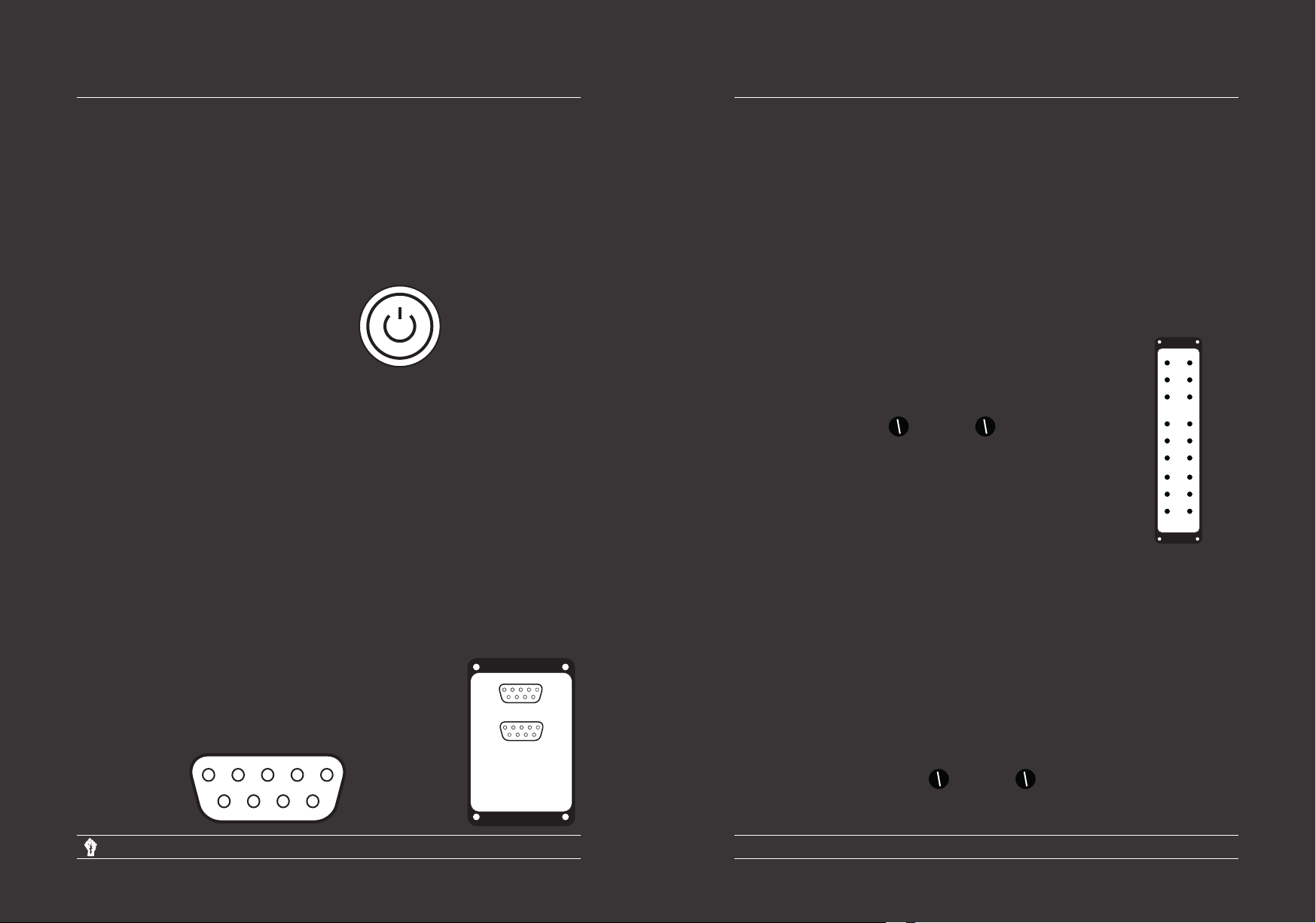
Push the power button:
Now the light in the power button will illuminate, and
the machine generate sa few clicks from the
relays. Now the tubes heat up, inside
them a physical process occures named ‘the
Edison effect’ and electrons will flow into the
micro universe of the tube. The gain reduction
meters measure the current trough the tubes
responsible for the compression and the leds of
the meters will lit up. After 30 to 60 seconds
the machine is ready for operation.
III.
2
Balance measurement
The machine is calibrated in our factory, however
the procedure is as follows. The tubes can drift
directly after the warm up so it is recommended to
leave the unit on for half an hour, before
calibration /measurement. For this procedure is
needed:
-a flat screwdriver
-a (digital) multimeter
Remove the the measurement panel.
Behind the measurement panel there
are two 9pins d-sub sockets, with the
numbering of pins:
5 4 3 2
9 8 7 6
1
Power
5 4 3 2
9 8 7 6
Right
5 4 3 2
9 8 7 6
Left
Pinout
1, 2: High
3, 4: Mid
5, 6: Low
7, 8: Main
9 : Gnd
If an unbalance is measured, second
order harmonics occure. To rebalance
the stage, apply the multimeter to the
correct stage (see III.2) and use the flat
screw driver to adjust the balance
trim-pot until the multimeter indicates
0 volts.
bal
III.
4
Meter zero/bias
While tubes age, their conductance decrease and
therefore the gain reduction meters will indicate
compression. Although this is not immediately a
problem, there is a way to recalibrate the idle
current of the tubes. Use a flat screwdriver to
adjust the zero pot-meter of the desired channel
1
1
(mid, high, low, and left or right) and set the
meter to 0 dB. If thie problem is not solved, a
tube replacement may be necessary. After
altering the bias, it is recommended to re balance
the stage.
level
zero
bal
r
l
i
e
g
f
h
t
t
level
zero
bal
level
zero
bal
zero
Electric Signal MMXV AD
Page 9
Delta Transconductace band Compressor
User Manual
Page 10
Page 7

III.
5
Output stage balance/
This procedure is equal to the delta mu gain
stages; if an inbalance is measured at pin 7 and
8, the balance needs to be recalibrated. The
balance pots are next to the 6h30 tubes. (see
visual below)
measurement
III.
6
There is a possibility that an imbalance may exist
between the levels low/mid/high and left/right.
These imperfections can be set properly
by adjusting the level trim-pots. They can
atttenuate 2.5dB.
Level
level
left balance
right balance
IV
The next chapters describe
how the machine can be used. Due to the high
amount of controls, compared to other
compressors, the front panel may be a bit
overwhelming, but is actually simple if familiar.
Remember there are three elements: Main, filter
and compressors. The controls for the
compressors are arranged in a matrix. This
matrix is present in the whole front panel design
exept for the filter and main section. The
controls for the filters are divided in two
sections, because there are two crossover
frequency’s. Furthermore all secondary functions
are engraved in red and all controls (besides the
calibration trim-pots) operates the left and the
right channel. As mentioned before, due to the
relative large number of operations and the
axiom; ‘a shorter signal pad is in most cases
better’ the Delta Transconductance band
Compressor uses more than 100 signal relays
and they may give a light ‘clicking’ sound if a
control is used.
On the next page there is a visual of the block
chain of the machine. In the manual and
on the front panel, the three compressors of the
machine will be defined by high, mid and low
channel. Once the filter is bypassed
this definition
(high, mid, low) it may partially loose it’s meaning, so
for example; bypassing the low pass filter of the
high to mid section resulting in the ‘high’
compressor working over the whole (20hz20kHz) frequency range.
Using the system
Electric Signal MMXV AD
Page 11
Delta Transconductace band Compressor
User Manual
Page 12
Page 8

I V. 1
Block chain
of system
Input
transformer
Main input
-∞
Input gain
Gain reduction
Input gain
Gain reduction
level
Balance
leds
measurement
level
Balance
leds
measurement
voltage
controlled amp
Meter zero Balance Attack time Release time
voltage
controlled amp
Meter zero Balance Attack time Release time
Side chain
0.1
0.01
0.6
0.04
0.3
0.05
0.8
0.08
1.0
0.10
1.5
0.13
4.0
100
130
0.1
0.6
0.3
0.8
1.0
1.5
4.0
100
130
34
20
50
34
20
50
Side chain
0.2
1.2
0.5
1.5
0.8
1.8
0.01
0.04
0.05
0.08
0.10
0.13
0.2
1.2
0.5
1.5
0.8
1.8
Threshold Stereo link
Threshold Stereo link
mono
link
mono
link
High mute Recovery gain
-∞
High mute Recovery gain
Σ
Audio signal
Control signal
Main output
-∞
Main mute
output
transformer
On
XLR Input
Electric Signal MMXV AD
Filter
System bypass
Input gain
Gain reduction
-∞
level
Balance
leds
measurement
voltage
controlled amp
Meter zero Balance Attack time Release time
Side chain
0.1
0.6
0.3
0.8
1.0
1.5
4.0
34
20
50
100
130
Page 13
High mute Recovery gain
0.01
0.04
0.05
0.08
0.10
0.13
0.2
1.2
0.5
1.5
0.8
1.8
Threshold Stereo link
mono
link
Delta Transconductace band Compressor
User Manual
XLR Output
Page 14
Page 9
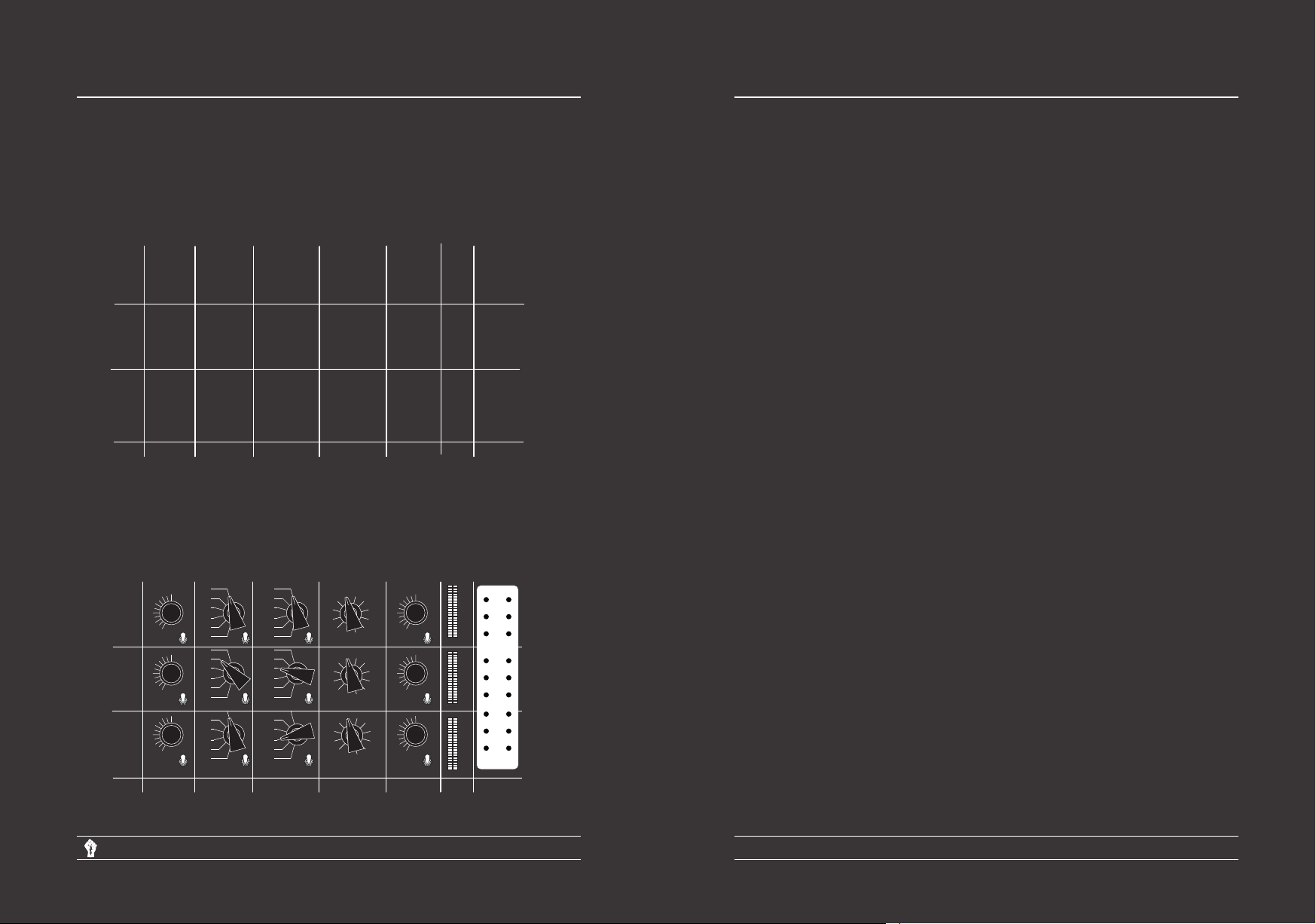
I V.
2
Control Matrix
IV.
2.1
Input Gain
Behold the following visual: This is a manipulated
image from the front panel; the control, main and
the filter section are edited out. What is left is an
empty matrix.
High
Mid
Low
Input Gain (dB)/
stereo link
Attack time (ms)/
time adder
Recovery time (s)/
time adder
Threshold (dBu) Recovery gain
(dB)/mute
The controls are arranged in that matrix:
off
on
off
on
off
on
0.01
0.04
0.05
0.08
0.10
0.13
0.2
1.2
0.5
1.5
0.8
1.8
0.01
0.04
0.05
0.08
0.10
0.13
0.2
1.2
0.5
1.5
0.8
1.8
0.01
0.04
0.05
0.08
0.10
0.13
0.2
1.2
0.5
1.5
0.8
1.8
Recovery time (s)/
time adder
31
0 5
-2
-8
off
on
off
on
off
on
out
31
0 5
-2
-8
out
31
0 5
-2
-8
out
Threshold (dBu) Recovery gain
6
3
7
0
9-6
-3
14
-6
6
3
7
0
9-6
-3
14
-6
6
3
7
0
9-6
-3
14
-6
(dB)/mute
Mid
High
Low
12
9
6
3
0
-3
12
9
6
3
0
-3
12
9
6
3
0
-3
Input Gain (dB)/
stereo link
mono
link
mono
link
mono
link
0.1
0.6
0.3
0.8
1.0
1.5
4.0
34
20
50
100
130
0.1
0.6
0.3
0.8
1.0
1.5
4.0
34
20
50
100
130
0.1
0.6
0.3
0.8
1.0
1.5
4.0
34
20
50
100
130
Attack time (ms)/
time adder
This Control is an 11 position rotary switch, and
controls a relay based attenuater with a
resolution of 1.5dB per step. Together with the
Threshold control this defines the slope and the
threshold of the compression curve.
IV.
The attack control determines the speed with
which the compressor attacks a level above the
threshold point. It also determines the ratio of
action the compressor will have on short
duration spikes and transients.
Gain
Calibration
reduction
IV.
It determines the time-rate of compression holding
action. Increasing the control clockwise lengthens
the holding time.
IV.
0.2
9
9
9
0
-0.5
level
-1
-2
-3
mute
l
e
f
on
t
mute
l
on
e
f
t
mute
on
Gain
reduction
bal
-20
r
i
g
h
t
0.2
0
-0.5
-1
-2
-3
-6
-8
-10
-14
-20
r
i
g
h
t
0.2
0
-0.5
-1
-2
-3
-6
-8
-10
-14
-20
l
e
f
t
level
zero
bal
level
zero
bal
Calibration
r
i
g
h
t
zero
-6
-8
-10
-14
The threshold control is used to adjust the
amount of compression in conjunction with the
input gain. With the control in the full clockwise
position (out), there will be no compression.
Turning the control anti-clockwise increases the
amount of compression.
IV.
This Control is an 11 position rotary switch and
controls a relay based attenuater with a
resolution of 1.5dB per step. Besides amplefying
the signal after compression, this control can be
used to mix the low, mid and high band together.
2.2
2.3
2.4
2.5
Attack time
Release time
Threshold
Recovery gain
Electric Signal MMXV AD
Page 15
Delta Transconductace band Compressor
User Manual
Page 16
Page 10

IV.
2.6
Stereo link
IV.
4
Main output
When switched to “mono”, the amount of
compression of the right channel is independent
of the left channel. When switched to “link” the
control voltage is combined, left and right
channel are reduced in gain by the same number
of dB.
IV.
Mutes the channel.
IV.3
2.7
Mute
Gain reduction
meters
Six meters, mid, high, low and left.right measure
the current trough the remote cutoff valves
responsible for the gain reduction/compression
and therefore measures the gain reduction. Over
time while the tubes age and the conductance of
them lowers, the meters may drop. However the
bias can be recalibrated if this occurs (see III.3)
24 position rotary switch, controls the output
gain, with a resolution of 1 dB per step.
IV.
If the main output rotary switch is turned
completelyanti clockwise to the - the output is
muted.
IV.
4.1
4.2
Main Mute
Main system
bypass
Removes all the electronics from the signal chain
and links the input to the output, see the block
chain IV.1.
IV.
11 position rotary switch, controls the output
gain, with a resolution of 1dB per step, Notify that
this control can effect every compressor in the
unit. In combination with the input gain 121
gain combinations are possible
4.3
Main input
Electric Signal MMXV AD
Page 17
Delta Transconductace band Compressor
User Manual
Page 18
Page 11

V. 1
Filter
Block chain
high to mid
highpass filter
bp
high
pass
high to mid
highpass filter
bp
high
pass
high to mid
lowpass filter
Bypass
On
high to mid
highpass filter
order
6 dB
/oct
12 dB
/oct
high to mid
order
1st order
2nd order
6dB/oct
high pass filter
1.0k
3.8k 4.8k
Crossover frequency
-3dB fc
1.5k
1.2k
6.2k 8.0k 10k 14k
high to mid
-6dB fc
12dB/oct
high pass filter
2.3k
1.8k
High
output
Phase
inverter
3.0k
Bypass
Filter
intput
high to mid
highpass filter
Audio signal
Control signal
Filter I/O
On
Bypass
high to mid
highpass filter
order
-6dB fc
2nd order
-3dB fc
1st order
low pass filter
2nd order
low pass filter
mid to low
highpass filter
bp
high
pass
mid to low
highpass filter
bp
high
pass
mid to low
lowpass filter
mid to low
highpass filter
On
On
Bypass
1st order 1st order
mid to low
highpass filter
order
6 dB
/oct
12 dB
/oct
mid to low
order
mid to low
highpass filter
order
1st order
2nd order
2nd order
6dB/oct
high pass filter
1.0k
3.8k 4.8k
Crossover frequency
-3dB fc
1st order
low pass filter
-3dB fc
1.5k
1.2k
6.2k 8.0k 10k 14k
mid to low
-6dB fc
12dB/oct
high pass filter
2.3k
1.8k
2nd order
low pass filter
Mid
output
3.0k
-6dB fc
Low
out
put
Phase
inverter
Electric Signal MMXV AD
Page 19
Delta Transconductace band Compressor
User Manual
Page 20
Page 12
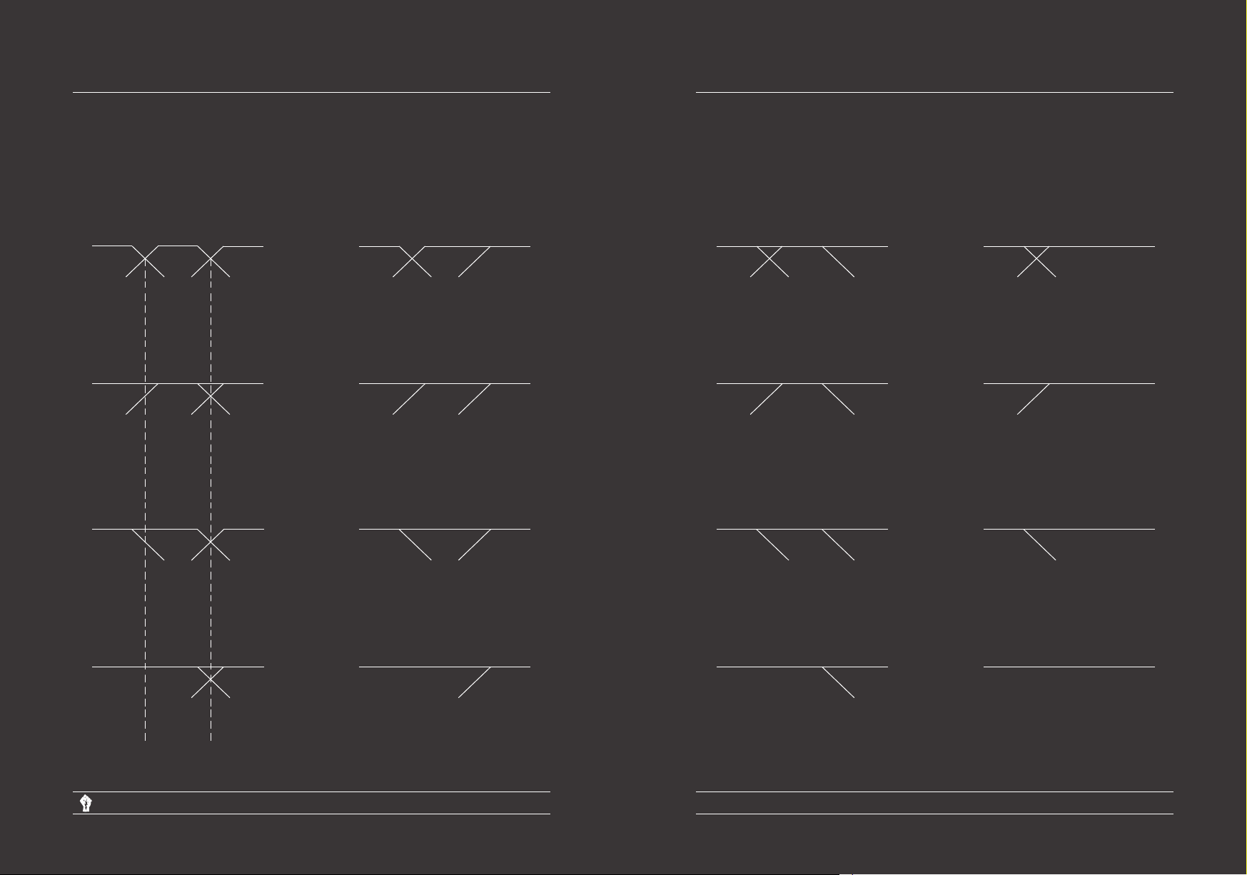
V.
2.1
filter setting
high to mid 6dB/oct - mid to low 6dB/oct
Bode plot’s of
-
high to mid hp:on lp:on
mid to low hp:on lp:on
high to mid hp:on lp:on
mid to low hp:on lp:off
high to mid hp:on lp:on
mid to low hp:off lp:on
high to mid hp:on lp:off
mid to low hp:on lp:on
high to mid hp:on lp:off
mid to low hp:on lp:off
high to mid hp:on lp:off
mid to low hp:off lp:on
high to mid hp:off lp:on
mid to low hp:on lp:on
high to mid hp:off lp:on
mid to low hp:on lp:off
high to mid hp:off lp:on
mid to low hp:off lp:on
high to mid hp:off lp:off
mid to low hp:on lp:on
high to mid hp:off lp:off
mid to low hp:on lp:off
high to mid hp:off lp:off
mid to low hp:off lp:on
high to mid hp:on lp:on
mid to low hp:off lp:off
mid to low
crossover
frequency
high to mid
crossover
frequency
Electric Signal MMXV AD
high to mid hp:on lp:off
mid to low hp:off lp:off
Page 21
high to mid hp:off lp:on
mid to low hp:off lp:off
Delta Transconductace band Compressor
User Manual
high to mid hp:off lp:off
mid to low hp:off lp:off
Page 22
Page 13
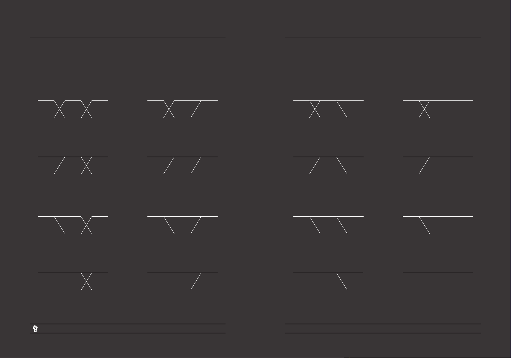
V.
2.2
filter setting
high to mid 12 dB/oct - mid to low 12 dB/oct
Bode plot’s of
-
high to mid hp:on lp:on
mid to low hp:on lp:on
high to mid hp:on lp:on
mid to low hp:on lp:off
high to mid hp:on lp:on
mid to low hp:off lp:on
high to mid hp:on lp:off
mid to low hp:on lp:on
high to mid hp:on lp:off
mid to low hp:on lp:off
high to mid hp:on lp:off
mid to low hp:off lp:on
high to mid hp:off lp:on
mid to low hp:on lp:on
high to mid hp:off lp:on
mid to low hp:on lp:off
high to mid hp:off lp:on
mid to low hp:off lp:on
high to mid hp:off lp:off
mid to low hp:on lp:on
high to mid hp:off lp:off
mid to low hp:on lp:off
high to mid hp:off lp:off
mid to low hp:off lp:on
high to mid hp:on lp:on
mid to low hp:off lp:off
Electric Signal MMXV AD
high to mid hp:on lp:off
mid to low hp:off lp:off
Page 23
high to mid hp:off lp:on
mid to low hp:off lp:off
Delta Transconductace band Compressor
User Manual
high to mid hp:off lp:off
mid to low hp:off lp:off
Page 24
Page 14

V.
2.3
filter setting
high to mid 6 dB/oct - mid to low 12 dB/oct
Bode plot’s of
-
high to mid hp:on lp:on
mid to low hp:on lp:on
high to mid hp:on lp:on
mid to low hp:on lp:off
high to mid hp:on lp:on
mid to low hp:off lp:on
high to mid hp:on lp:off
mid to low hp:on lp:on
high to mid hp:on lp:off
mid to low hp:on lp:off
high to mid hp:on lp:off
mid to low hp:off lp:on
high to mid hp:off lp:on
mid to low hp:on lp:on
high to mid hp:off lp:on
mid to low hp:on lp:off
high to mid hp:off lp:on
mid to low hp:off lp:on
high to mid hp:off lp:off
mid to low hp:on lp:on
high to mid hp:off lp:off
mid to low hp:on lp:off
high to mid hp:off lp:off
mid to low hp:off lp:on
high to mid hp:on lp:on
mid to low hp:off lp:off
Electric Signal MMXV AD
high to mid hp:on lp:off
mid to low hp:off lp:off
Page 25
high to mid hp:off lp:on
mid to low hp:off lp:off
Delta Transconductace band Compressor
User Manual
high to mid hp:off lp:off
mid to low hp:off lp:off
Page 26
Page 15

V.
2.4
filter setting
high to mid 12dB/oct - mid to low 6dB/oct
Bode plot’s of
-
high to mid hp:on lp:on
mid to low hp:on lp:on
high to mid hp:on lp:on
mid to low hp:on lp:off
high to mid hp:on lp:on
mid to low hp:off lp:on
high to mid hp:on lp:off
mid to low hp:on lp:on
high to mid hp:on lp:off
mid to low hp:on lp:off
high to mid hp:on lp:off
mid to low hp:off lp:on
high to mid hp:off lp:on
mid to low hp:on lp:on
high to mid hp:off lp:on
mid to low hp:on lp:off
high to mid hp:off lp:on
mid to low hp:off lp:on
high to mid hp:off lp:off
mid to low hp:on lp:on
high to mid hp:off lp:off
mid to low hp:on lp:off
high to mid hp:off lp:off
mid to low hp:off lp:on
high to mid hp:on lp:on
mid to low hp:off lp:off
Electric Signal MMXV AD
high to mid hp:on lp:off
mid to low hp:off lp:off
Page 27
high to mid hp:off lp:on
mid to low hp:off lp:off
Delta Transconductace band Compressor
User Manual
high to mid hp:off lp:off
mid to low hp:off lp:off
Page 28
Page 16

V.
3
Filter
V.
3.2
Lp bypass
In general, the filter splits the signal in a low, mid
a high band. furthermore the filter settings
enables the user to enables/bypass filters and
sets the order or bypass all the filters to enable
paralell compression. The next subjects besides
cross over frequency discribes one of the two
filter sections but they work equally.
V.
3.1
Paralell compression
New York compression, mowtown compression
or parralell compression is one or more
compressors working paralell on the same
material and later mixed together. Often, a
heavy compressed signal is combined with an
ligtly or uncompressed signal. The filter bypass
function makes it possible to change from a band
compressor to a set of three stereo
compressors configured in paralell, wich enables
paralell compression.
The bode plot’s in the prevous chapters indicates
that if the machine is set as three paralell
compressors, the order and filter crossover
frequency cotrol has no function, see for
example the right bottom bode plot (V.2.1-V.2.1)
V.
3.1
Crossover frequency
Activates or bypasses the lowpass filter, see
V.2.1 to V.2.4
V.
3.3
Activates or bypasses the highpass filter. see
V.2.1 to V.2.4
V.
3.4
This cotrol defines the rollof slope, choose
beteween first order(6dB/oct) of second order
(12dB/oct). The first order filter crossoverpoint
is at -3dB. And the second order filter is -6dB.
Hp bypass
Order
See V.2.1and V.1, Controls the crossover
frequency of the low passfilter and the highpass
filter. Notify the frequency multiplier switch(1x
white or 4x red) so Twelve cross over frequency
values can be set,
Electric Signal MMXV AD
Page 29
Delta Transconductace band Compressor
User Manual
Page 30
Page 17

VI.
Tubes for replacement can be obtained from our
factory.
The Delta Transconductance band compressor
uses the following thermionic tubes:
12X 6ba6/5749/6k4p Compression
3X 6H30 Input/output
2X 6H2p(-ev/-er) Mixing
4X 12AT7/ECC83 PI/tonecontrol
1
Tube complement
VI
.2 Replacing the tubes
6h2p
Notify that the remote cutoff tubes, responsible
for the compression(6ba6/5749/6k4p) need to
be matched pairs. The 5749W (wich comes with
the compressor) is an joint Army Navy electron
tube from General Elecric.
The two 6h30 for the output need to be
matched triodes.
The Delta Transconductance band compressor
comes with two russian milspec 6h2p-er,
responsible for mixing, if desired to use an
european ecc81or an nowadays 12ax7 make
use of a ecc to 6h2p socket (contact electric
signal for more information)
Not every ECC83 is usable due to the maximum
rating specifications, contact electric signal for
more information.
See next subject for tube replacement.
6h30
ecc81/12at7
6ba6/5749/6k4p
To remove a tube, press the screening can down
and twist anti-clockwise, when it will spring out.
Then remove the tube by pulling upwards,
possibly using a cloth if it’s still hot. Take care
not to bend the pins when putting back in.
Electric Signal MMXV AD
Page 31
Delta Transconductace band Compressor
User Manual
Page 32
Page 18

VII.
Electric Signal reserves the right to alter
specifications without prior notice. Electric Signal
cannot be held responsible for any damage
resulting in using the Delta Transconductace
band Compressor.
VII.
The unit comes with a 24 month warranty
covering parts and labor, It is essential that it is
returned to our factory or to the dealer from
which it was purchased for repairs to be carried
out otherwise the warranty is invalidated.
Contact Electric Signal how to send it to us.
1
2
Disclaimer
Warrenty
VII
Power consumption
Frequency responce
Input impedance
Output impedance
Signal to noise
Operating voltage
Attack time
Release time
Specifications
15k
Weight
THD
600
>80dB
200Watt max
12kg
240vac/130vac
0,1%
-1dB 12Hz-30KHz
0,1-130ms
10ms-1s
Electric Signal MMXV AD
Page 33
Delta Transconductace band Compressor
User Manual
Page 34
Page 19

IX
Edison Effect
X
Declaration of
Confirmity
Edison Effect or Thermionic emission:
Thermionic emission is the thermally induced
flow of charge carriers from a surface or over a
potential-energy barrier. This occurs because the
thermal energy given to the carrier overcomes
the work function of the material. The charge
carriers can be electrons or ions, and in older
literature are sometimes referred to as
"thermions". After emission, a charge that is
equal in magnitude and opposite in sign to the
total charge emitted is initially left behind in the
emitting region. But if the emitter is connected
to a battery, the charge left behind is neutralized
by charge supplied by the battery as the emitted
charge carriers move away from the emitter, and
finally the emitter will be in the same state as it
was before emission.
The classical example of thermionic emission is
the emission of electrons from a hot cathode
into a vacuum (also known as thermal electron
emission or the Edison effect) in a vacuum tube.
The hot cathode can be a metal filament, a
coated metal filament, or a separate structure
of metal or carbides or borides of transition
metals. Vacuum emission from metals tends to
become significant only for temperatures over
1,000 Kelvin The science dealing with this
phenomenon has been known as "thermionics",
but this name seems to be gradually falling into
disuse.
The Delta Transconductance band Compressor
complies with the requirements of Conformité
Européenne.
XI
Contact details
www Electricsignal.eu
@ info@electricsignal.eu
Phone 0031640237096
Leiden, Netherlands
2332PZ
Electric Signal
Electric Signal MMXV AD
Page 35
Delta Transconductace band Compressor
User Manual
Page 36
Page 20

XII
Recall sheet
Delta Transconductance Band Compressor
High
Mid
Low
12
9
6
3
0
-3
12
9
6
3
0
-3
12
9
6
3
0
-3
Input Gain (dB)/
stereo link
mono
link
mono
link
mono
link
0.1
0.6
0.3
0.8
1.0
1.5
4.0
34
20
50
100
130
0.1
0.6
0.3
0.8
1.0
1.5
4.0
34
20
50
100
130
0.1
0.6
0.3
0.8
1.0
1.5
4.0
34
20
50
100
130
Attack time (ms)/
time adder
0.01
0.04
0.05
0.08
0.10
0.13
0.2
1.2
0.5
1.5
off
0.8
1.8
on
0.01
0.04
0.05
0.08
0.10
0.13
0.2
1.2
0.5
1.5
off
0.8
1.8
on
0.01
0.04
0.05
0.08
0.10
0.13
0.2
1.2
0.5
1.5
off
0.8
1.8
on
Recovery time (s)/
time adder
0 5
-2
-8
off
on
0 5
-2
-8
off
on
0 5
-2
-8
off
on
Threshold (dBu) Recovery gain
1.5k
1.0k
31
7
9-6
14
out
31
7
9-6
14
out
31
7
9-6
14
out
9
6
3
0
-3
mute
-6
on
9
6
3
0
-3
mute
-6
on
9
6
3
0
-3
mute
-6
on
(dB)/mute
1.2k
3.8k 4.8k
bp
high
pass
High to mid
6080100 130 180 240
300 370
bp
high
pass
Mid to low
Crossover frequency
(Hz)/filter settings
2.3k
1.8k
6.2k 8.0k 10k 14k
12 dB
/oct
bp
low
6 dB
pass
/oct
450
530 660
12 dB
/oct
bp
low
6 dB
pass
/oct
3.0k
1x
4x
800
1x
4x
0.2
-2.5
-12
-15
-20
r
l
i
e
g
f
h
t
t
0.2
-2.5
-12
-15
-20
r
l
i
e
g
f
h
t
t
0.2
-2.5
-12
-15
-20
Gain
reduction
0
-8
0
-8
0
-8
Calibration
Bal measurement
-10
Calibration settings
behind this panel
-16
-18
Main Calibration
settings
behind this panel
-4-6
-8
Input (dB)/
system bypass
-10-12
-14
-20
-∞
0
-22
Output (dB)
Main
Power
-2
0
bp
on
-8
-6
-4
-2
Electric Signal
MMXV AD
Electric Signal MMXV AD
Page 37
Delta Transconductace band Compressor
User Manual
Page 38
 Loading...