


TERMOSTATI ELETTRONICI
INSTALLAZIONE DA PARETE O DA SEMINCASSO
SURFACE-MOUNTED OR SEMI FLUSH-MOUNTED
ELECTRONIC THERMOSTATS
THERMOSTATS ÉLECTRONIQUES POUR
MONTAGE EN SAILLIE OU SEMI-ENCASTRÉ
ELEKTRONISCHER THERMOSTAT FÜR WANDMONTAGE
ODER EINGELASSENE INSTALLATION
TERMOSTATOS ELECTRÓNICOS
DE PARED O SEMIEMPOTRADO
PE - DETENN500 07/18

GB - English
IT - Italiano
DATI TECNICI - ISTRUZIONI PER L’INSTALLAZIONE
MODO D’IMPIEGO
Pagina 3
EN - English
FR - Français
DE - Deutsch
ES - Espanòl
2
TECHNICAL DATA - INSTALLATION GUIDELINES
USER INSTRUCTIONS
DONNÉES TECHNIQUES - NORMES D’INSTALLATION
MODE D’EMPLOI
TECHNISCHE DATEN - NORMEN FÜR DIE INSTALLATION
BEDIENUNGSANLEITUNG
DATOS TÉCNICOS - NORMAS DE INSTALACIÓN
INSTRUCCIONES PARA EL USUARIO
Page 10
Page 17
Seite 24
Página 31
AVVERTENZE PER LA SICUREZZA
Si raccomanda di leggere attentamente le presentiistruzionidiinstallazioneedusoeconservarleperfutureconsultazioni.
Il costruttore si riserva la facoltà di introdurre tutte le modifiche tecniche e costruttive che riterrà necessarie senza obbligo
di preavviso.
Assicurarsi di aver toltol’alimentazione direte230Vprima di procedere all’installazione oalla manutenzione.
DATI TECNICI
Tensione di alimentazione:
Tipo azione, disconnessione, apparecchio:
Tipo di uscita:
Collegamento utenza (carico):
Ingressi per comando remoto di “Riduzione”:
Sezione max dei fili ai morsetti:
Tipo di isolamento:
Grado di protezione:
Grado di inquinamento:
Limiti della temperatura di funzionamento:
Limiti della temperatura di stoccaggio:
Scala di regolazione temperatura:
Limite di temperatura max impostabile:
Riduzione della temperatura:
Precisione di lettura della temperatura:
Tipo di funzionamento:
Funzionamento differenziale:
Gradiente termico:
Classificazione energetica ERP
Normative di riferimento per marcatura CE:
230 V~ 50 ÷ 60 Hz
1/ B / Elettronico
a relè con contatto in scambio NA / COM / NC
libero da potenziale - max 8(2) A / 250 V~
2 o 3 conduttori
per contatto libero da potenziale (mod. predisposti)
alimentazione = 2,5 mm
contatto relè = 2,5 mm
riduzione remota = 1,5 mm (mod. predisposti)
classe II
I30P
normale
0 °C ÷ +50 °C
-10 °C ÷ +65 °C
+5 °C ÷ +30 °C
16,18, 20, 22, 24 °C (impostabile con disco range)
- 4 °C dal set di temperatura impostato
± 1 °C
ON/OFF con differenziale
t = 0,4 °C (fisso)D
1 °K/15 min
ErP: Class I; 1% Reg. EU 811/2013
LVD EN60730-2-9 EMC EN60730-2-9
2
2
2
IT
3

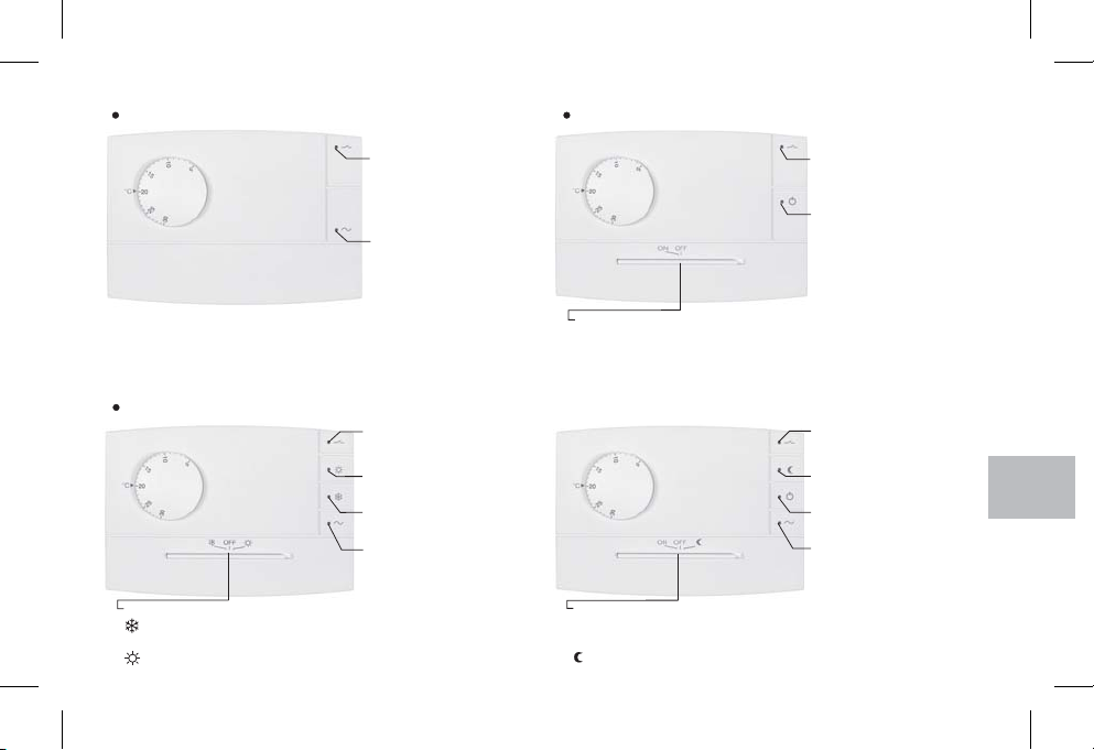
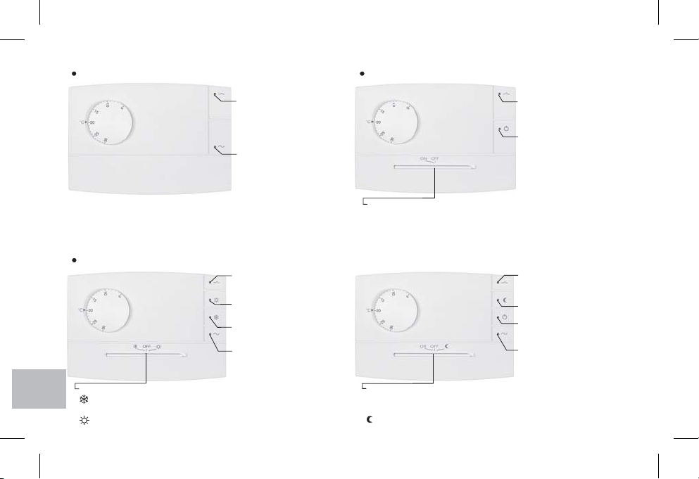
Modello con:
Ingresso per comandoremotodiriduzione della temperatura
IT
G
B
Modello con:
Ingresso per comandoremotodiriduzione della temperatura
LED rossostato delrelè
(acceso =utenza attivata)
LED verdealimentazione
(acceso =presenza direte)
LED rossostato delrelè
(acceso =utenza attivata)
LED rossofunzione ESTATE
(acceso =raffrescamento)
LED rossofunzione INVERNO
(acceso =riscaldamento)
LED verdealimentazione
(acceso =presenza direte)
Modello con:
Ingresso per comandoremotodiriduzione della temperatura
LED rossostato delrelè
(acceso =utenza attivata)
LED rossotermostato infunzione
(acceso =termoregolazione attivata)
Commutatore:
ON=termoregolazione attivata
OFF = termoregolazione disattivata
Modello con:
LED rossostato delrelè
(acceso =utenza attivata)
LED rosso termoregolazione in
riduzione
LED rossotermostato infunzione
(acceso =termoregolazione attivata)
LED verdealimentazione
(acceso =presenza direte)
Commutatore:
INVERNO =funzionamentoriscaldamento
OFF = termoregolazionedisattivata
ESTATE= funzionamento raffrescamento
4
Commutatore:
ON=termoregolazioneattivata
OFF = termoregolazionedisattivata
= termoregolazione inriduzione (funzionamento -4 °Cdal set ditemperatura impostato)
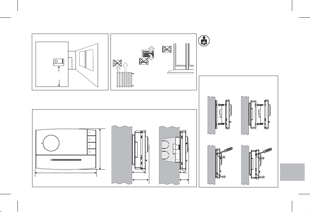
ESEMPI DI INSTALLAZIONE
OK!
h 1,5 m
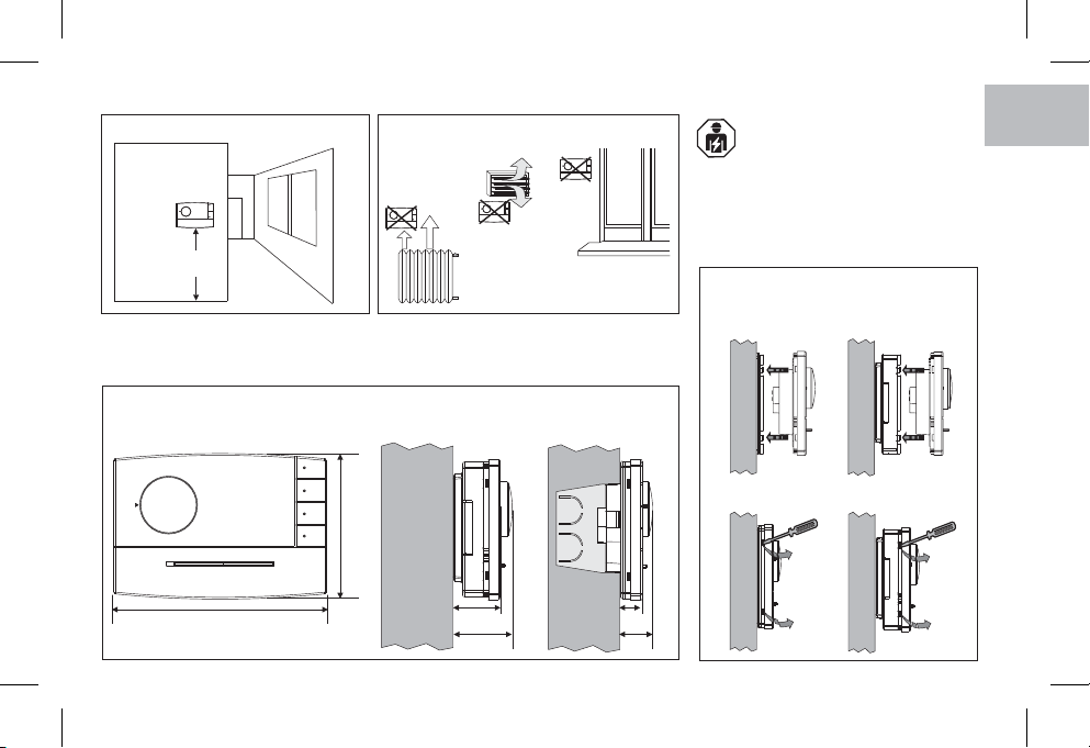
Installare preferibilmente il termostato a quota 1,50 ÷ 1,70 m dal pavimento; lontano da
sorgenti di calore, prese d'aria, porte o finestre e da quanto possa influenzarne il
funzionamento.
DIMENSIONI DI INGOMBRO
modello aparete modello asemincasso
82
Importante: l'installazione edil collegamento
elettrico deldispositivodevonoessere
eseguiti solo da elettricista qualificato ed in
conformità alle norme e leggi vigenti. Il costruttore
non si assume alcuna responsabilità per quanto
concerne l’impiego di prodotti che debbano seguire
particolari norme diambiente e/o installazione.
Fissaggio e rimozione del
termostato
IT
120
27,5
33,5
12,5
18,5
5

INSTALLAZIONE DEL TERMOSTATO
IT
G
Modelli per installazione a SEMINCASSO
B
Modelli per installazione a PARETE
A
B
A
A
A
D
D
Supporto per installazione a semincasso del termostato
A Fori di fissaggio del supporto:-
su scatola ad incasso tonda o rettangolare
B Passaggio fili da:-
Scatola ad incasso tonda o rettangolare,
tubo corrugato (per modello a parete)
C Fori di fissaggio della base:-
a parete, su scatola ad incasso tonda o rettangolare
D Dentini di fissaggio termostatoE Passaggi per fili da canalina a parete (asportare diaframma)-
6
Per assicurare un corretto
montaggio del termostato al
supporto o alla base a parete,
gli stessi non devono
presentare incurvature dovute
all’eccessivo serraggio delle
viti di fissaggio nella scatola
tonda orettangolareincassata
a muro.
B
C
C
E
E
E
D
D
Base per installazione a parete del termostato
(per fissare direttamente la base a muro utilizzare appositi
tasselli nonforniti)

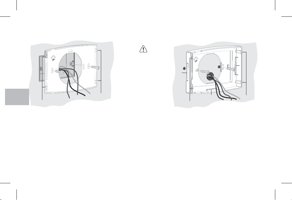
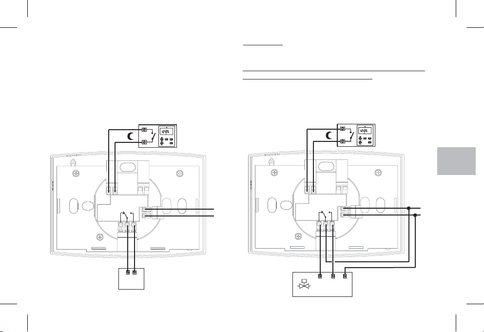
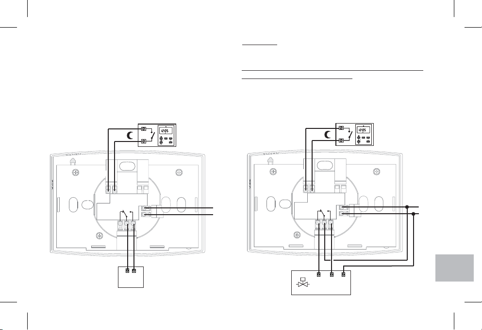
COLLEGAMENTI ELETTRICI
disattivare la tensione di rete
Collegare l’alimentazione di rete 230V~ ai morsetti:
n° =1 Linea
n° =2 Neutro
Collegare i fili del dispositivo da comandare ai morsetti:
n° = contattonormalmente aperto3
n° = comune4
n° = contattonormalmente chiuso5
Ingresso riduzione
(modelli predisposti)
7
6
89
SEC
SEC
ON
ON
5
5
7
7
4
4
123
6
123
6
DayDay
OkOk
YYMMChCh
ResetReset
ProgProg
esempio
Interruttore orario
Importante: con forti carichiinduttivi (pompeed elettrovalvole)
si consiglia di collegare un filtro RC in parallelo al carico.
Collegamenti per la selezione remota della temperatura
"Riduzione" solo su modelli predisposti
Qualora si desideri utilizzare la selezione remota della
temperatura “Comfort" o "Riduzione", provvedere al
collegamento del contatto esterno (privo di potenziale) ai
morsetti: n° e n° del termostato.67
SEC
SEC
ON
ON
esempio
5
5
7
7
4
4
123
6
123
89
6
DayDay
OkOk
YYMMChCh
ResetReset
ProgProg
Interruttore orario
Ingresso riduzione
(modelli predisposti)
7
6
IT
1
2
5
3
4
L
230 V ~
N
Caldaia
5
3
4
Chiude
1
2
N
Elettrovalvola motorizzata
Apre
L
230 V ~
N
7

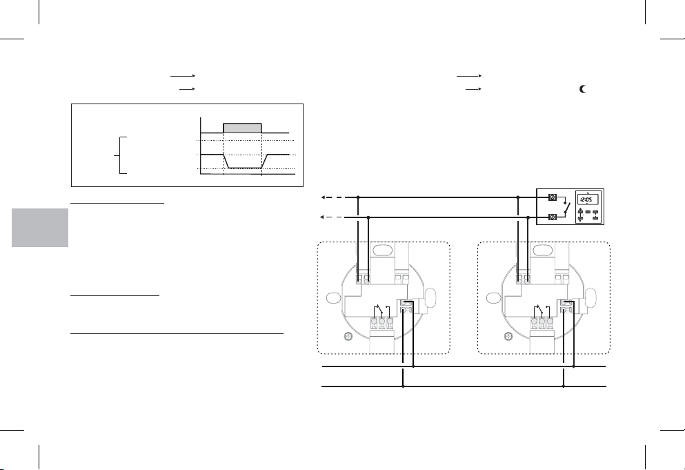
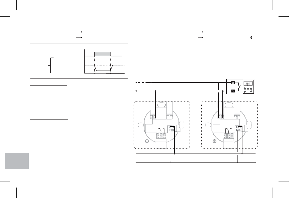
Principio di funzionamento delcomandoabordo o remoto di riduzionedellatemperatura(per modelli predisposti)
IT
Temperatura “ ”Comfort Contatto remoto aperto
G
Temperatura “ ”Riduzione Contatto remoto chiuso
B
Esempio
Temperatura
ambiente
Contatto
24 °C
T set (Comfort) = 20 °C
16 °C
Aperto
Chiuso
Riduzione
h 22:00
Installazioni multiple
Nelle installazioni multiple (vedi uffici, scuole, abitazioni,
ecc.) comandate per la riduzione notturna centralizzata
h 6:00
Aperto
La selezione della temperatura di “Riduzione”
determina una riduzione di 4 °C, rispetto al
valore di set impostato della temperatura.
Temperatura “ ”Comfort Commutatore in posizione ON
Temperatura “ ”Riduzione Commutatore in posizione
Interruttore orario
M1
M2
da un solo interruttore orario, è necessario attenersi
scrupolosamente alle seguenti indicazioni (figura a lato).
Per tutti i termostati
Alimentazione (230V~)
7
6
89
7
6
Tutti i morsetti n° : collegare la Linea1
Tutti i morsetti n° : collegare il Neutro2
Collegamenti per comando riduzione notturna
Tutti i morsetti n° : collegare in parallelo con uscita6 M1
1
2
del comando remoto (interruttore orario).
5
3
Tutti i morsetti n° : collegare in parallelo con uscita7 M2
del comando remoto (interruttore orario).
Nota per l’installatore: nell’esecuzionedei collegamenti elettrici, nelcaso diinstallazione a parete senzascatola incasso,prestareparticolare attenzione
affinché ilcablaggio siaben disposto enon interferiscacon la correttachiusura deltermostato.
8
TERMOSTATO
4
TERMOSTATO
5
3
4
SEC
SEC
ON
ON
5
5
7
7
4
4
123
6
123
6
DayDay
OkOk
YYMMChCh
ResetReset
ProgProg
89
1
2
L
230 V ~
N
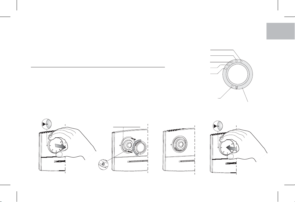
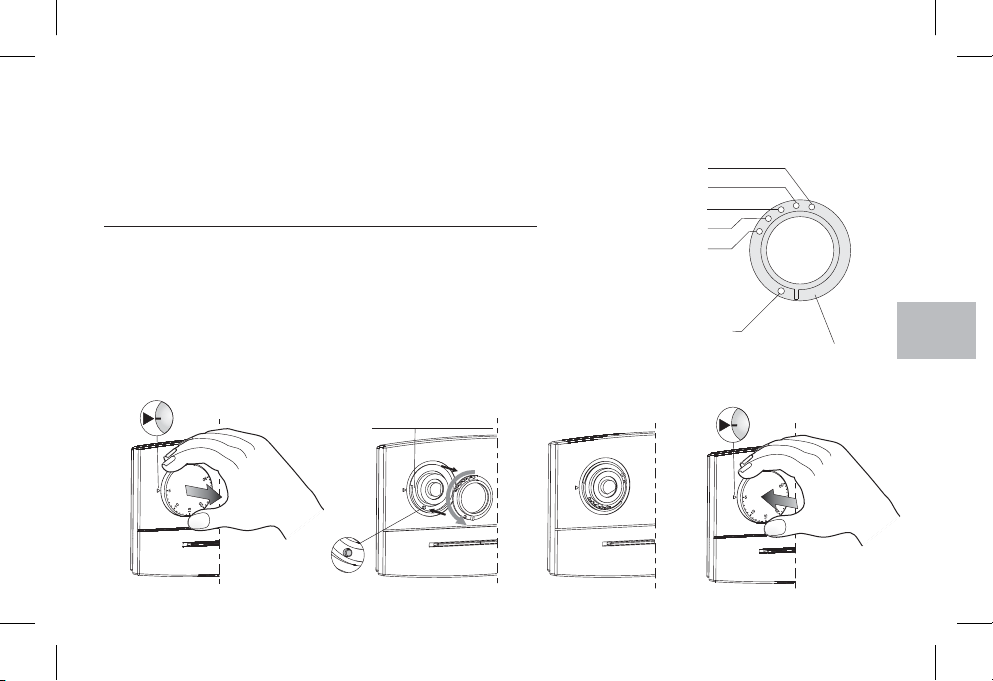
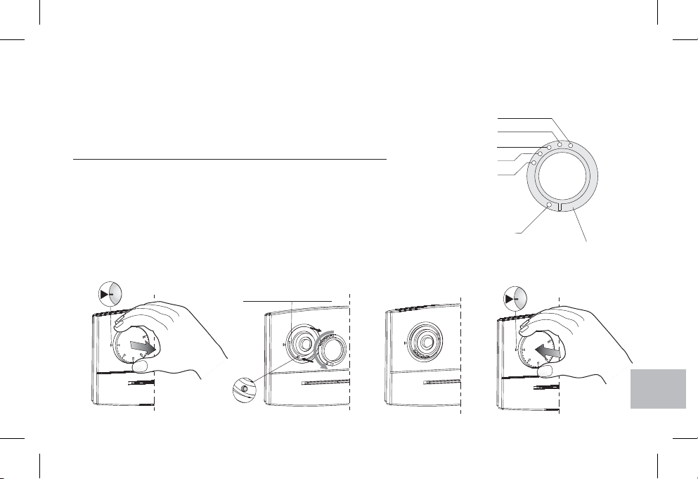
LIMITAZIONE TEMPERATURA MASSIMA DELL’AMBIENTE
E' possibile prefissare da 16 °C a 24 °C, con step di 2 °C, il massimo valore di temperatura
impostabile.
N.B.: il termostato viene fornito con il "disco range" preinstallato con il perno nel foro
neutro (nessuna limitazione di temperatura).
Impostazione del limite ditemperaturaosua successiva modifica
a) Ruotare la manopola in corrispondenza dei (30 °C per modelli in funzionamento5°C
Estate) ed estrarla.
b-c) Estrarre il "disco range", quindi reinserirlo facendo corrispondere il foro relativo alla
temperatura massima desiderata con il perno situato sul termostato.
d) Reinserire la manopola avendo cura di inserirla nella medesima posizione che aveva in
precedenza; posizione dei (30 °C per modelli in funzionamento Estate) in
corrispondenza dell’indice presente sul frontale del termostato.
5°C
IT
Fori per limitazione set di temperatura
16 °C
18 °C
20 °C
22 °C
24 °C
(± 0,5 °C)
Foro neutro
Disco range
a)
Perno
Sede disco range
c)
5
d)
9
5
b)

SAFETY PRECAUTIONS
Read this manual carefully beforeusingtheproductasitprovidesimportant guidelines regarding safety,installation and use.
The manual must be preserved with care for future reference. The manufacturer reserves the right to introduce any technical
and/or constructive changes deemed necessary, with no prior notice.
Before starting anyoperations onthedevice, disconnect the 230V~ mainspower supply
EN
G
TECHNICAL DATA
DATI TECNICIDATI TECNICI
Supply voltage:
B
Type of action, disconnect and device:
Type of output:
Output connection (load):
Inputs for “Reduction” control, remote:
Maximum wire section at terminals:
Insulation type:
Protection degree:
Pollution:
Operating temperature limits:
Storage temperature limits:
Temperature adjustment range:
Settable max. temperature limit:
Reduction temperature:
Precision of reading of the temperature:
Operation:
Differential operation:
Thermal gradient:
ERP Energy classification:
Reference standard for CE mark:
10
230 V~ 50 ÷ 60 Hz
1/ B / Electronic
relay with changeover contact NO / COM / NC
voltage free - max 8(2)A / 250 V~
2 or 3 conductors
for voltage free contact (models where provided for)
supply voltage = 2,5 mm
relay contact = 2,5 mm
reduction remote = 1,5 mm2(models where provided for)
Class II
I30P
Normal
0 °C ÷ +50 °C
-10 °C ÷ +65 °C
+5 °C ÷ +30 °C
16,18, 20, 22, 24 °C (settable with range disc)
- 4 °C from temperature setpoint
± 1 °C
ON/OFF with differential
Dt = 0,4 °C (fixed)
1 °K/15 min
ErP: Class I; 1% Reg. EU 811/2013
LVD EN60730-2-9 EMC EN60730-2-9
2
2

Model with:
Input for remotecontroltemperaturereduction
Model with:
Input for remotecontroltemperaturereduction
Model with:
Input for remotecontroltemperaturereduction
Relay statusred LED
(alight =load ON)
Summer operationred LED
(alight =cooling)
Winter operationred LED
(alight =heating)
Supply voltage green LED
(alight = power ON)
Switch
WINTER= heatingoperation
OFF = thermoregolationOFF
SUMMER=coolingoperation
Relay statusred LED
(alight =load ON)
Supply voltage green LED
(alight = power ON)
Relay statusred LED
(alight =load ON)
Thermostat Onred LED
(alight =thermoregulation ON)
Switch:
ON=thermoregolationON
OFF = thermoregolationOFF
Model with:
Relay statusred LED
(alight =load ON)
Thermoregolation reductionred LED
Thermostat Onred LED
(alight =thermoregulation ON)
Supply voltage green LED
(alight = power ON)
Switch:
ON=thermoregolationON
OFF = thermoregolationOFF
= thermoregolation inreduction (operation -4°C from theset temperature)
EN
11

INSTALLATIONEXAMPLES
OK!
EN
G
B
h 1,5 m
Install the thermostat at a heightof 1,5m ÷1,7 mfrom thefloor, far fromheat sources, air
vents, doors or windows and anything else that could affect its operation
.
Important: t lhe installationandelectrica
connections ofdevicesandappliancesmust
be implemented by person with
electrotechnical expertise only and in conformity
with current laws and regulations. The manufacturer
declines any liability in connection with the use of
products subject to special environmental and/or
installation standards.
Fixing and removing the
thermostat
DIMENSIONS
12
120
model
surface mounting
82
27,5
33,5
model
semi flush mounting
12,5
18,5

THERMOSTAT INSTALLATION
Models for SEMI FLUSH mounting
Models for SURFACE mounting
A
B
A
A
A
D
D
Support for thermostat semi flush mounting
A - Holes for fixing the support:
to round or rectangular flush-mounted box
B - Passage of wires from:
Round or rectangular flush-mounted box,
corrugated tube (for surface-mounted model)
C - Holes for fixing the base:
D - Thermostat fixing teeth
E - Passages for wires from wall raceway (remove diaphragm)
To ensure correct fitting of the
thermostat to the support or
surface-mounted base, make
sure the latter arenot distorted
by overtightening of the fixing
screws in the round or
rectangular flush-mounted
box.
E
D
Base for thermostat surface mounting
(to fixthe base directly tothe wall, use specialplugs
not supplied)
to wall, to round or rectangular flush-mounted box
B
C
C
E
E
D
EN
13

ELECTRICAL CONNECTIONS
Switch mains supply off
Connect 230V ~ power supply to the terminals:
n° =1 Line
n° =2 Neutral
Connect the controlled device to the terminals:
n° = normallyopen contact3
EN
n° = common4
G
n° = normallyclosed contact5
B
Reduction input
(models where
provided for)
123
123
YYMMChCh
SEC
SEC
5
5
7
7
4
4
6
6
DayDay
ResetReset
ON
ON
OkOk
time switch
ProgProg
example
IMPORTANT: for heavy inductive loads (pumps and solenoid
valves) it is advisable to connect an RC filter in parallel with the
load.
Connections for the temperature "Reduction" remote
control (models where provided for)
If you want to use remote control of or“Comfort" "Reduction"
temperature, connect the exterior contact (potential-free) to the
terminals: n° and n° of thethermostat.67
SEC
SEC
ON
ON
example
5
5
7
7
4
4
123
6
123
Reduction input
(models where
provided for)
YYMMChCh
6
DayDay
OkOk
ResetReset
ProgProg
time switch
67 89
1
2
5
3
4
L
230 V ~
N
Heater
14
67 89
1
2
5
3
4
Open
Close
N
Motorized valve
L
230 V ~
N

Workingprinciple of theonboard orremotetemperature reduction control(models where provided for)
“ ” TemperaturComfort e
“ ” TemperaturR du ionect e
Example
Ambient
temperature
T set (Comfort) = 20 °C
Open remote c conta t
Closed remote contact
Conta tc
Open
24 °C
16 °C
h 22:00
Closed
R du ionect
Open
h 6:00
“ ” TemperaturComfort e
“ ” TemperaturR du ionect e
Selecting “Reduction” (Economy)
temperature determinesadecreaseof 4 °C
with respect to the set temperature value.
Multiple installations
Besides all that has been mentioned above, in multiple
installations (for example offices, schools, houses,
etc.) operated only by one clock for the centralized
night reduction, it is necessary to follow carefully the
indications below.
7
6
89
Forall thermostats
Supply voltage (230V~)
All terminals n° : connect the Line1
All terminals n° : connect the Neutral2
1
2
Connections for night reduction control
5
3
All terminals n°. : connect in parallel with output6 M1
of the remote control (time switch)
THERMOSTAT
4
All terminals n°. : connect in parallel with output7 M2
of the remote control (time switch)
Note forthe contractor:make the electricalconnections takingparticular care inthe eventof surface mountingwithout boxthat the
wires are correctly arranged and do not hinder a proper fit between the body and thebase.
Switch in position ON
Switch in position
Time switch
M1
M2
7
6
1
2
5
3
THERMOSTAT
4
89
123
123
YYMMChCh
SEC
SEC
ON
ON
5
5
7
7
4
4
6
6
DayDay
OkOk
ResetReset
ProgProg
230 V ~
EN
L
N
15

LIMITATION OF THE MAXIMUM ROOM TEMPERATURE
It is possible to preset from 16 °C to 24 °C, with 2 °C step, the maximum temperature value.
NB: the thermostat is supplied with the "range disc" preinstalled with pin in the neutral hole
(no temperature limitation).
Temperature limit settingor itssubsequent modification
EN
G
B
a) Turn the knob to the (30 °C for models in Summer mode) mark; then remove the5°C
knob.
b-c) Take out the “temperature range” disc and reinsert it by locating the maximum
desired temperature hole over the pin placed on thermostat.
d) Replace the knob, making certain it is positioned as before: (30 °C for models in
Summer mode) position coinciding with the index on the front of the case.
5°C
Holes for temperature setpoint limitation
16 °C
18 °C
20 °C
22 °C
24 °C
(± 0,5 °C)
Neutral hole
Range disc
5
a)
16
b)
Pin
Range disc seat
c)
5
d)

MESURES DE SÉCURITÉ
Il est recommandé de lire avec attention les présentes instructions d'installation et d'utilisation et de les conserver pour de
futures consultations. Le fabricant se réserve la faculté d'apporter toutes les modifications techniques et de construction qu'il
jugera nécessaires sans obligation de préavis.
Avant d'effectuer tout travailsur ledispositif,couperl'alimentationduréseau 230V~.
DONNÉES TECHNIQUES
Tension d’alimentation:
Type d’action, déconnexion et appareil:
Type de sortie:
Connexion asservissement (charge):
Entrées pour commande “Réduction”, à distance:
Section maximum des fils aux bornes:
Type d’isolation:
Degré de protection:
Pollution:
Limites de la température de fonctionnement:
Limites de la température de stockage:
Echelle de réglage de la température:
Limite de température maxi programmable:
Réduction de la température:
Précision de lecture de la température:
Fonctionnement:
Fonctionnement différentiel:
Gradient thermique:
Classement énergétique ERP:
Normatives de référence pour le label CE:
230 V~ 50 ÷ 60 Hz
1/ B / Electronique
A relais avec contact d’échange NO / COM / NF
libre de potentiel - max 8(2)A / 250 V~
2 ou 3 conducteurs
pour contact libre de potentiel (modèles pré-équipés)
alimentation = 2,5 mm
contact relais = 2,5 mm
réduction à distance = 1,5 mm (modèles pré-équipés)
Classe II
I30P
Normale
0 °C ÷ +50 °C
-10 °C ÷ +65 °C
+5 °C ÷ +30 °C
16,18, 20, 22, 24 °C (réglable à l'aide du disque gamme de température)
- 4 °C de la plage de température programmée
± 1 °C
ON/OFF avec différentiel
t = 0,4 °C (fixe)D
1 °K/15 min
ErP: Class I; 1% Reg. EU 811/2013
LVD EN60730-2-9 EMC EN60730-2-9
2
2
2
FR
17

Modèle avec:
Entrée pour commandeàdistancede la réductiondelatempérature
Modèle avec:
Entrée pour commandeàdistancede la réductiondelatempérature
Rouge (DEL)état durelais
(allumée =charge activée)
Vert(DEL)alimentation
(allumée =présence duréseau)
FR
G
Modèle avec:
B
Entrée pour commandeàdistancede la réductiondelatempérature
Rouge (DEL)état durelais
(allumée =charge activée)
Rouge (DEL)fonctionnement ETÉ
(allumée =réfroidissement)
Rouge (DEL) fonctionnementHIVER
(Allumée = réchauffement)
Vert(DEL)alimentation
(allumée =présence duréseau)
Commutateur:
HIVER =fonctionnementréchauffement
OFF = réglagethermique désactivé
ETÉ =fonctionnementréfroidissement
18
Rouge (DEL)état durelais
(allumée =charge activée)
Rouge (DEL)thermostat enservice
(allumée =réglage thermiqueactivé)
Commutateur:
ON=réglage thermique activé
OFF = réglagethermique désactivé
Modèle avec:
Rouge (DEL)état durelais
(allumée =charge activée)
Rouge (DEL)réglage thermique
en réduction
Rouge (DEL)thermostat enservice
(allumée =réglage thermiqueactivé)
Vert(DEL)alimentation
(allumée =présence duréseau)
Commutateur:
ON=réglage thermique activé
OFF = réglagethermiquedésactivé
= réglage ther miqueen réduction (-4°C référéà la température programmée)

EXEMPLES D’INSTALLATION
OK!
h 1,5 m
Si possible,installer le thermostatà1,50÷ 1,70 mdu sol etàbonnedistance des sources
de chaleur, des prises d’air, des portes ou des fenêtres et de tout ce qui peut agir sur le
fonctionnement.
DIMENSIONS DU THERMOSTAT
modèl en saillie modèl semi-encastré
82
Important: 'installation et lebranchementl
électrique desdispositifsetappareils
doivent être effectués par un électricien
qualifié et conformément aux normes et aux lois
en vigueur. Le constructeur n'assume aucune
responsabilité en ce qui concerne l'utilisation des
produits qui doivent suivre des normes
particulières concernant l'environnement et/ou
l'installation.
Fixation et démontage du
thermostat
FR
120
27,5
33,5
12,5
18,5
19
INSTALLATION DU THERMOSTAT
Modèles pour montage SEMI-ENCASTRÉ
Modèles pour montage EN SAILLIE
A
B
A
A
A
FR
G
B
D
Plaque pour montage semi-encastré du thermostat
20
Pour un montage correct du
thermostat sur la plaque ou la
base murale, celles-ci ne
doivent pas être courbées à
cause d'un serrage excessif
des vis de fixation à la boîte
ronde ou rectangulaire
encastrée danslemur.
E
D
Base pour montage en saillie du thermostat
(pour fixer directement la base au mur, utiliser des chevilles
appropriées nonfournies)
A Trous de fixation de la plaque:-
sur boîte à encastrer ronde ou rectangulaire
B Passage des fils de:-
boîte à encastrer ronde ou rectangulaire,
gaine (pour mod. à montage mural)
C Trous de fixation de la base:-
en saillie ou sur boîte à encastrer ronde ou rectangulaire
D Dents de fixation du thermostatE Passages pour fils sous gaine en saillie (enlever le diaphragme)-
B
C
C
E
E
D
D
BRANCHEMENTS ELECTRIQUES
Désactiver la tension du réseau
Brancher les fils d’alimentation 230V~ aux bornes:
n° =1 Ligne
n° =2 Neutre
Brancher les fils du dispositif à commander aux bornes:
n° = contactnormalement ouvert3
n° = commun4
n° = contactnormalement fermé5
Entrée “Réduction”
(modèles pré-équipés)
67 89
SEC
SEC
ON
ON
5
5
7
7
4
4
123
6
123
6
DayDay
OkOk
YYMMChCh
ResetReset
ProgProg
exemple
Interrupteur horaire
IMPORTANT: en cas de fortes charges inductives (pompes et
électrovalves), il est conseillé de raccorder un filtre RC en
parallèle à la charge.
Connexions pour la commande à distance de "Réduction"
de la température (modèles pré-équipés)
Pour utiliserla sélection àdistance dela température “Confort"/
"Réduction", brancher le contact extérieur (sans potentiel) aux
bornes: n° et n° du thermostat.67
SEC
SEC
ON
ON
exemple
5
5
7
7
4
4
123
6
123
Entrée “Réduction”
(modèles pré-équipés)
67 89
6
DayDay
OkOk
YYMMChCh
ResetReset
ProgProg
Interrupteur horaire
FR
1
2
5
3
4
L
230 V ~
N
Boiler
1
2
5
3
4
N
Vanne motorisée
Ouvert
Fermé
L
230 V ~
N
21
Principe de fonctionnement de lacommande embarquée ou à distance deréduction delatempérature(modèles pré-équipés)
Température “ ”Comfort Contact à distance ouvert
Température “ ”Réduction Contact à distance fermé
Exemple
Temp raturée
ambi ntea
Conta tc
24 °C
T set (Comfort) = 20 °C
16 °C
Ouvert
Fermé
R du ionéct
h 22:00
Installation multiples
Dans le cas des installations multiples (voir bureaux,
écoles, maisons d’habitation, etc.) commandées pour
FR
G
la réduction nocturne centralisée par un seul
interrupteur horaire,ilfaut s’en tenirscrupuleusement à
B
ce quivient d’être dit, ainsiqu’aux indications suivantes
(figure ci-contre).
h 6:00
Ouvert
Température “ ”Comfort
Température “ ”Réduction
La sélection de la température "Réduction"
engendre une réduction de4 °C,parrapport
à la valeur programmée de la température.
7
6
89
Commutateur position: ON
Commutateur position:
Interrupteur horaire
M1
M2
7
6
Pour tous les thermostats
Alimentation (230V~)
Toutes les bornes n° : brancher Ligne1
Toutes les bornes n° : brancher Neutre2
1
2
Branchements pour commande réduction nocturne
Toutes les bornes n° : brancher en parallèle avec6
sortie de la commande à distance (inter. horaire).M1
THERMOSTAT
5
3
4
THERMOSTAT
5
3
4
Toutes les bornes n° : brancher en parallèle avec7
sortie de la commande à distance (inter. horaire).M2
Note pour l’installateur:exécuter les branchementsélectriques, en prêtant une attention particulière en cas de montage en saillie
sans boîte à encastrer,en faisantensortequelescâblagesoitbienposéetqu’ilnegênepaslabonnefermetureducorps.
22
SEC
SEC
ON
ON
5
5
7
7
4
4
123
6
123
6
DayDay
OkOk
YYMMChCh
ResetReset
ProgProg
89
1
2
L
230 V ~
N
LIMITATION DE LA TEMPÉRATURE AMBIANTE MAXIMALE
Il est possible de programmer la valeur maximum de température programmable de 16 °C
à 24 °C avec des pas de 2 °C.
N.B.: le thermostat est livré avec un "disque gamme de température" pré-installé, son axe
se trouvant dans le trou neutre (aucune limite de température).
Réglage de la limitedetempératureet modification successive
a) Mettre la manette au niveau de (30 °C pour les modèles en fonctionnement Été);5°C
sortir la manette.
b-c) Extraire le disque “gamme de température” et le remettre en place en faisant
correspondre le trou de la température maximum souhaitée avec l’axe sur la façade
du thermostat.
d) Remettre la manette en place en veilant à l’introduire dans la même position que celle
d’avant: position des (30 °C pourles modèlesen fonctionnementÉté) au niveau de
l’indice présent sur la façade du dispositif.
5
5°C
Logement du disque
gamme de température
Axe
Trous pour limiter la plage de température
16 °C
18 °C
20 °C
22 °C
24 °C
(± 0,5 °C)
Trou neutre
Disque gamme
de température
5
FR
a)
b)
c)
d)
23
SICHERHEITSVORKEHRUNGEN
Es wirdempfohlen, die vorliegende Montage- und Gebrauchsanweisung aufmerksam durchzulesenundfür spätere Fragen aufzubewahren.
Der Hersteller behält sich das Recht vor, technische Modifikationen und Konstruktionsänderungen, die der Produktverbesserung dienen,
ohne vorherige Ankündigungvorzunehmen.
VorderAusführungjeglicherArbeitenam Gerät ist dieNetzversorgung 230V~zuunterbrechen
TECHNISCHE DATEN
Versorgungsspannung:
DATI TECNICIDATI TECNICI
Antrieb, Trennen der Verbindung und Gerät:
Ausgang:
Anschluss des Verbrauchers (Last):
G
Eingänge für Fernsteuerung “Reduzierung”:
Kabelquerschnitt für Klemmen:
B
Isolierung:
Schutzart:
Verschmutzungsgrad:
Betriebstemperatur:
DE
Lagerungstemperatur:
G
Temperaturregelung Skala:
B
Max. einstellbare Temperaturbegrenzung:
Nachtbetrieb Temperatur (Reduktionstemperatur):
Präzision der Temperaturlektüre:
Funktionsweise:
Differentielle Funktionsweise:
Temperaturgradient:
Energieklassifizierung ErP:
Referenznormen für CE - Zeichen:
24
230 V~ 50 ÷ 60 Hz
1/ B / Elektronisches Gerät
Relais mit unipolarem Weichenkontakt
NO / COM / NC und potentialfrei 8(2)A / 250 V~
2 oder 3 Leiter
Für potentialfreier Wechselkontakt (Modelle mit Vorrüstung)
Versorgungsspannung = 2,5 mm
Relaiskontakte = 2,5 mm
Eingang Reduzierung = 1,5 mm (Modelle mit Vorrüstung)
Klasse II
I30P
Normal
0 °C ÷ +50 °C
-10 °C ÷ +65 °C
+5 °C ÷ +30 °C
16,18, 20, 22, 24 °C (Einstellbar mit Scheibe Temperaturbereich)
- 4 °C vom eingestellten Temperatursollwert
± 1 °C
ON/OFF mit Differenzwert
t = 0,4 °C (fix)D
1 °K/15 min
ErP: Class I; 1% Reg. EU 811/2013
LVD EN60730-2-9 EMC EN60730-2-9
2
2
2
Modell mit:
Eingang für FernsteuerungzurReduzierung der Temperatur
Modell mit:
Eingang für FernsteuerungzurReduzierung der Temperatur
Rote LEDRelaiszustands
(leuchtet =Ladefunktion aktiviert)
Grüne LEDVersorgungsspannung
(leuchtet =Netzversorgung)
Modell mit:
Eingang für FernsteuerungzurReduzierung der Temperatur
Rote LEDRelaiszustands
(leuchtet =Ladefunktion aktiviert)
Rote LEDSOMMER Betrieb
(leuchtet =Kühlen)
Rote LEDWINTER Betrieb
(leuchtet =Heizen)
Grüne LEDVersorgungsspannung
(leuchtet =Netzversorgung)
Umschalter:
WINTER = Heizen Betrieb
OFF = temperaturregelung deaktiviert
SOMMER = Kühlen Betrieb
Rote LEDRelaiszustands
(leuchtet =Ladefunktion aktiviert)
Rote LED-AnzeigeThermostatbetrieb
(leuchtet =temperaturregelung aktiviert)
Umschalter:
ON=temperaturregelung aktiviert
OFF=temperaturregelung deaktiviert
Modell mit:
Rote LEDRelaiszustands
(leuchtet =Ladefunktion aktiviert)
Rote LED-Anzeige Temperaturregelung
Reduzierung
Rote LED-Anzeige Thermostatbetrieb
(leuchtet = temperaturregelung aktiviert)
Grüne LEDVersorgungsspannung
(leuchtet =Netzversorgung)
Umschalter:
ON= temperaturregelung aktiviert
OFF = temperaturregelung deaktiviert
= temperaturregelung Reduzierung(betrieb-4°C voneingegebenerTemperatur)
DE
25

INSTALLATIONSBEISPIELE
OK!
h 1,5 m
Bringen Sie den Thermostat möglichst in einer Höhe von 1,5 m ÷ 1,7 m, entfernt von
Wärmequellen, Luftzufuhrgittern, Fenestern und Türen und weiteren den Betrieb des
Gerätes beeinträchtigenden Gegenständen bzw.Umständen an
ABMESSUNGEN
Modell Wandmontage Modell Eingelassene
DE
G
B
82
Die InstallationundderelektrischeAnschluß
der Geräte muß durch nur von
Elektrofachkraft und in Übereinstimmung mit den
geltenden Vorschriften und gesetzlichen
Bestimmungen vorgenommen werden. Der
Hersteller übernimmt keine Haftung für die
Verwendung von Produkten, für die besondere
Umgebungs- und/oder Installationsbedingungen
erfüllt werden müssen.
BEFESTIGUNG UND AUSBAU
DES THERMOSTATS
120
26
27,5
33,5
12,5
18,5

INSTALLATION DER GERÄTS
Modelle für EINGELASSENE Installation
Modelle für WANDMONTAGE
A
B
A
A
A
D
D
Halterung für eingelassene Thermostinstallation
A - Bohrungen zur Befestigung der Halterung:
auf rundem oder rechteckigem Unterputzgehäuse
B - Kabeldurchführung vom:
rundem oder rechteckigem Unterputzgehäuse,
geripptem Rohr (für Wandmodelle)
C - Bohrungen zur Befestigung der Basis:
an der Wand, auf rundem oder auf dem rechteckigem Unterputzgehäuse
D - Befestigungsklauen des Thermostats
E - Kabeldurchführung vom Kabelkanal zur Wand (Membran ausbrechen)
Für die korrekte Montage des
Thermostats auf der Halterung
oder der Wandbasis dürfen
sich dieselben nicht durch zu
starkes Festziehen der
Befestigungsschrauben auf
dem runden oder rechteckigen
Unterputzgehäuse verziehen.
B
C
C
E
E
E
D
D
Basis für Wandmontage des Thermostaten
(Bei direkterWandmontage der BasisDübel verwenden nicht
im Lieferumfanginbegriffen)
DE
27

ELEKTRISCHE ANSCHLÜSSE
Trennen sie das stromnetz ab
Versorgungskabel (230 V~) an die klemmen angeschlossen:
n° =1 Leitung
n° =2 Neutralleiter
Das zu steuernde Gerät mit den Klemmen:
n° = Kontakt Ruhestellungoffen3
n° = Gemeinsam4
n° = Kontakt Ruhestellunggeschlossen5
Eingang "Reduzierung"
(Modelle mit Vorrüstung)
SEC
SEC
4
4
123
123
DayDay
YYMMChCh
ON
ON
5
5
7
7
6
6
OkOk
ResetReset
ProgProg
Beispiele
Zeitschaltuhr
HINWEIS: bei starken induktiven Lasten (Pumpen und
Elektroventile) wird empfohlen einen RC-Filter parallel zu
schalten.
Anschlüsse für die Fernsteuerung der Temperatur "Reduzierung" (Modelle mit Vorrüstung)
Für die Nutzung der Temperatur-Fernsteuerung “ ” /Komfort
“ ” den externen Kontakt (ohne Spannung) an dieReduzierung
Klemmen und des Thermostats anschließen67 .
SEC
SEC
ON
ON
Beispiele
5
5
7
7
4
4
123
6
123
Eingang "Reduzierung"
(Modelle mit Vorrüstung)
YYMMChCh
6
DayDay
OkOk
ResetReset
ProgProg
Zeitschaltuhr
DE
67 89
1
2
5
3
4
L
230 V ~
N
Kessel
28
67 89
1
2
5
3
4
Offnet
Schließt
N
Motorisiertes Ventil
L
230 V ~
N

Funktionsprinzipder Temperaturreduzierung aufdemGerät oder mit Fernsteuerung(Modelle mit Vorrüstung)
Temperatur “ omfort”K K kt Fernsteuerung offenonta
Temperatur “Reduzierung” K kt Fernsteuerung geschlossenonta
Beispiele
Raumtemperatur
Kkonta t
24 °C
T set ( omfort) = 20 °CK
16 °C
Offen
22:00 Uhr
Geschlossen
R duzieert
6:00 Uhr
Offen
Die Auswahl der Temperatur “Reduzierung”
führt zu einer Verringerung von 4 °C in Bezug
auf den eingestellten Temperatursollwert.
Mehrfachinstallationen
Bei Mehrfachinstallationen (z.B. in Büros, Schulen,
Wohnungen usw.), die zur zentralisierten nächtlichen
Absenkung der Temperatur durch eine einzige Uhr gesteuert
werden, müssen außer den obigen Angaben die folgenden
Anleitungen sorgfältig eingehalten werden (siehe abbildung).
Für alle Thermostate
6
Versorgungsspannung (230V~)
Alle Klemmen nr. : Leitung1
Alle Klemmen nr. : Neutralleiter2
Anschlüsse für die Fernsteuerung zur Reduzierung
Nachttemperatur
Alle Klemmen nr. : parallel an Ausgang der6 M1
Fernsteuerung anschließen (Zeitschaltuhr).
THERMOSTAT
Alle Klemmen nr. : parallel an Ausgang der7 M2
Fernsteuerung anschließen (Zeitschaltuhr).
Hinweis fürden Installateur: Führen SiedieelektrischenAnschlüsseauswobeiSieimFalleinerWandmontageohne Gehäuse besonders auf
den VerlaufderKabel achten sollen,damitdiesedieSchließung des Gerätekörpersnichtbeeinträchtigen.
Temperatur “Komfort” Umschalter: ON
Temperatur “Reduzierung” Umschalter:
7
89
1
2
5
3
4
THERMOSTAT
7
6
Zeitschaltuhr
M1
M2
89
1
2
5
3
4
123
123
YYMMChCh
SEC
SEC
ON
ON
5
5
7
7
4
4
6
6
DayDay
OkOk
ResetReset
ProgProg
230 V ~
DE
L
N
29

BEGRENZUNG DER MAXIMALEN RAUMTEMPERATUR
Der höchste einstellbare Temperaturwert kann in Schritten von 2 °C zwischen 16 und 24 °C
vorgegeben werden.
Hinweis: der Thermostat wird mit der werkseitig eingebauten "Scheibe Temperaturbereich"
geliefert; der Stift steckt in der Bohrung des Nullleiters (keine Temperaturbegrenzung).
Einstellung der Temperaturbegrenzungoder anschließendeÄnderung
a) Den Drehknopf auf 5 °C (30 °C für Modelle mit Sommerbetrieb) drehen und dann
herausziehen.
b-c) Die Scheibe "Temperaturbereich" herausziehen und mit dem an der Thermostat
befindlichen Stift in die Bohrung wieder einstecken, der der maximal gewünschten
Temparatur entspricht.
Bringen Sieden Drehknopf wiederan. Achten Siedabei darauf, dass dieser wieder
d)
in der gleichen Position wie zuvor eingesetzt wird Stellung 5 °C auf der Skala am
30 °C für Modelle mit Sommerbetrieb).
Gerät (
5
Sitz der Scheibe
Temperaturbereic
DE
Stift
Bohrungen für den Sollwert
der Temperaturbegrenzung
16 °C
18 °C
20 °C
22 °C
24 °C
(± 0,5 °C)
Neutrale
Bohrung
Scheibe
Temperaturbereich
5
a)
30
b)
c)
d)

PRECAUCIONES DE SEGURIDAD
Se recomienda leer con atención las presentes instrucciones de instalación y uso, conservándolas para futuras consultas.
El fabricante se reserva el derecho de realizar las modificaciones técnicas y de fabricación que considere oportunas, sin
obligación de aviso previo.
Antes de realizar cualquiertrabajo eneldispositivocorte la alimentaciónde redde230V~
DATOS TÉCNICOS
Tensión de alimentación:
Tipo de acción, disconexión, aparato:
Tipo de salida:
Conexión de los servicios (carga):
Entradas para mando remoto “Reducción”:
Sección max. de los cables a los terminales:
Tipo de aislamiento:
Grado de protección:
Polución:
Límites de temperatura de funcionamento:
Límites de temperatura de almacenaie:
Escala de regulación de temperatura:
Temperatura máxima programable:
Temperatura de reduccón:
Precisión de lectura de la temperatura:
Funcionamiento:
Funcionamiento diferencial:
Gradiente térmico:
Clasificación energética ERP
Normas de referencia para la marca CE:
DATI TECNICIDATI TECNICI
230 V~ 50 ÷ 60 Hz
1/ B / Electrónico
Relé con contacto en intercambio NA / COM / NC
libre de potencial - max 8(2) A / 250 V~
2 o 3 conductores
para contacto libre de potencial (modelos preparados)
alimentación = 2,5 mm
contacto de relé = 2,5 mm
reducción remota = 1,5 mm (modelos preparados)
Clase II
I30P
Normal
0 °C ÷ +50 °C
-10 °C ÷ +65 °C
+5 °C ÷ +30 °C
16,18, 20, 22, 24 °C (programable con disco rango)
-4 °C desde la temperatura programada
± 1 °C
ON/OFF con diferencial
Dt = 0,4 °C (fijo)
1 °K/15 min
ErP: Class I; 1% Reg. EU 811/2013
LVD EN60730-2-9 EMC EN60730-2-9
2
2
2
ES
31
Modelo con:
Entrada para mandoremotoparala reducción delatemperatura
Modelo con:
Entrada para mandoremotoparala reducción delatemperatura
LED rojode estadodel relé
(encendido =carga activada)
LED verdealimentación
(encendido =presencia dered)
Modelo con:
Entrada para mandoremotoparala reducción delatemperatura
LED rojode estadodel relé
(encendido =carga activada)
LED rojofuncionamiento VERANO
(encendido =refrigeración)
LED rojofuncionamiento INVIERNO
(encendido =calefacción)
LED verdealimentación
(encendido =presencia dered)
Conmutador:
ES
INVIERNO =funcionamientocalefacción
OFF = termorregulación desactivada
VERANO =funcionamientorefrigeración
32
LED rojode estadodel relé
(encendido =carga activada)
LED rojo termostato en funcionamiento
(encendido = termorregulación activada)
Conmutador:
ON=termorregulación activada
OFF = termorregulación desactivada
Modelo con:
LED rojode estadodel relé
(encendido =carga activada)
LED rojo termorregulación reducción
LED rojo termostato en funcionamiento
(encendido = termorregulación activada)
LED verdealimentación
(encendido =presencia dered)
Conmutador:
ON=termorregulaciónactivada
OFF = termorregulación desactivada
= termorregulación reducción (funcionamiento-4°C de latemperatura impostata)
EJEMPLOS DE INSTALACIÓN
OK!
h 1,5 m
Instalar, en preferencia, el termostato a1,5 m ÷ 1,7 mdel suelo;lejos de fuentesde
calor, respiraderos,puertas,ventanasuotroselementosque puedan influir en elfuncionamiento.
DIMENSIONES
modelo de pared modelo semiempotrada
82
La instalacióny la conexión eléctricade los
dispositivo y equipos deben ser realizadas
unicamente por electricistas especializados, de
conformidad con las normas y leyes vigentes. El
constructor no asume ninguna responsabilidad en lo
concerniente al empleo de productos que deban
seguir particulares normas ambientales y/o de
instalación.
Fijación y desmontaje del
termostato
120
27,5
33,5
12,5
18,5
ES
33

INSTALACIÓN DEL TERMOSTATO
Modelos para instalación SEMIEMPOTRADA
Modelos para instalación de PARED
A
B
A
A
A
D
D
Soporte para la instalación semiempotrada del termostato
A - Orificios de fijación del soporte:
B - Paso de los cables por:
C - Orificios de fijación de la base:
ES
34
D - Dientes de fijación del termostato
E - Pasos para cables por canaleta de pared (quitar el diafragma)
Para asegurar un correcto
montaje del termostato en el
soporte oen la basedepared,
estos no deben presentar
curvaturas debidas al apriete
excesivo de los tornillos de
fijación de la caja redonda o
rectangular empotrada en la
pared.
C
E
D
Base para la instalación de pared del termostato
(para fijardirectamente la basede pared, utilizartacos adecuados
no suministrados).
en caja de empotrar redonda o rectangular
Caja de empotrar redonda o rectangular,
tubo corrugado (para modelos de pared)
de pared, en caja de empotrar redonda o rectangular
B
C
E
E
D
CONEXIONES ELÉCTRICAS
Desactivar la tensión de red
Conecte los cables de alimentación 230V~ al borne:
n° =1 Línea
n° =2 Neutro
Conecte los cables del dispositivo accionador alborne:
n° = contactonormalmente abierto3
n° = común4
n° = contactonormalmente cerrado5
Entrada reducción
(modelos preparados)
SEC
SEC
ON
ON
5
5
7
7
4
4
123
6
123
6
DayDay
OkOk
YYMMChCh
ResetReset
ProgProg
ejemplo
Interruptor horario
Importante: si las cargas inductivas son fuertes (como en el
caso de lasbombas y elettroválvulas) se aconseja conectar un
filtro RC en paralelo a la carga.
Conexiones para el mando a distancia de reducción de la
temperatura (modelos preparados)
Para utilizar la opción remota de temperatura “Confort" /
"Reducción", hay que conectar el contacto externo (sin
potencial) a los bornes: n° y n° del termostato.67
SEC
SEC
ON
ON
ejemplo
5
5
7
7
4
4
123
6
123
Entrada reducción
(modelos preparados)
6
DayDay
OkOk
YYMMChCh
ResetReset
Interruptor horario
ProgProg
67 89
1
2
5
3
4
Caldera
L
230 V ~
N
67 89
1
2
5
3
4
Abierto
Cerrado
N
Válvula motorizada
L
230 V ~
N
ES
35
Principio defuncionamientodelmando de reduccióndela temperatura instaladoabordo o adistancia(modelos preparados)
Temperatura “ ”Co fortn Contacto remoto abierto
Temperatura “ ”Reducción Contacto remoto cerrado
Ejemplo
Temperatura
ambiente
Conta toc
24 °C
T set (Co fort) = 20 °Cn
16 °C
A ertobi
Rdu ineccó
h 22:00
Coerrad
A ertobi
h 6:00
Instalación múltiple
En las instalaciones múltiples (oficinas, escuelas,
viviendas, etc.) en las que un solo interruptor horario
Temperatura “ ”Comfort Conmutador en posición: ON
Temperatura “ ”Reducción Conmutador :en posición
La selección de la temperatura de
“Reducción” determina una disminución
de 4 °C con respecto a la temperatura
programada.
Interruptor horario
M1
M2
controla la reducción nocturna, es necesario atenerse
estrictamente a las seguientes indicaciones (ver fig. al
lado).
Para todos los termostatos
7
6
89
7
6
Alimentación (230V~)
Todos los bornes n° : conectar la Línea1
Todos los bornes n° : conectar el Neutro2
Conexiones para el mando de reducción nocturna
Todos los bornes n° : conectar en paralelo con6
salida del mando a distancia (interruptor horario).M1
Todos los bornes n° : conectar en paralelo con7
TERMOSTATO
1
2
5
3
4
TERMOSTATO
5
3
4
salida del mando a distancia (interruptor horario).M2
ES
Nota para el instalador: si eltermostatosemontadirectamenteenla pared sin cajaempotradahayqueprestarespecialatención a los cables,
que nodebenobstaculizarelcierredel cuerpo.
36
SEC
SEC
ON
ON
5
5
7
7
4
4
123
6
123
6
DayDay
OkOk
YYMMChCh
ResetReset
ProgProg
89
1
2
L
230 V ~
N
LÍMITE DE LA MÁXIMA TEMPERATURA AMBIENTE
Puede prefijarse de 16 °C a 24 °C con incrementos de 2 °C, el máximo valor de
temperatura que puede establecerse.
N.B.: el termostato posee un disco de rango preinstalado con el perno en el orificio neutro
(ninguna limitación de temperatura).
Programación del límite detemperaturaomodificación sucesiva
a) Gire el mando hasta la temperatura de (30° C para modelos en funcionamiento5°C
Verano)yextráigalo.
b-c) Extraiga el disco “rango de temperatura" y vuelva a introducirlo de manera que el
orificio de la temperatura máxima deseada coincida con el perno situado en la parte
frontal del termostato.
d) Volver a colocar el mando procurando introducirlo en la misma posición originaria; la
posición de los (30° C para modelos en funcionamiento Verano) tiene que
corresponder con el índice de la parte frontal del termostato.
5°C
Orificios para limitar la temperatura
programada
16 °C
18 °C
20 °C
22 °C
24 °C
(± 0,5 °C)
Orificio neutro
Disco rango de
temperatura
a)
5
Sede del disco de rango
Perno
5
ES
b)
c)
d)
37
SMALTIMENTODI VECCHIAPPARECCHIELETTRICI EDELETTRONICI
Questo simbolosul prodottoo sul suoimballo indicache questo prodottonon puòessere trattato comerifiuto domestico.
IT
Al contrario,dovrà essereportato ad unpunto diraccolta determinato peril riciclaggiodegli apparecchi elettricied elettronici,come ad esempio:
- puntivendita, nelcaso si acquistiun prodottonuovo simile aquello dasmaltire
- puntidi raccoltalocali (centri diraccolta rifiuti,centri locali diriciclaggio, ecc...).
AssicurandoVi che il prodotto sia smaltito correttamente, aiuterete a prevenire potenziali conseguenze negative per l'ambiente e la salute, che
potrebbero esserecausate daun inadeguato smaltimentodi questoprodotto.
Il riciclaggio dei materiali aiuterà a conservare le risorse naturali. Per informazioni più dettagliate riguardo il riciclaggio di questo prodotto,
contattate percortesia ilVs. ufficio locale,il Vs.servizio di smaltimentorifiuti domesticio il negoziodove aveteacquistato questo prodotto.
DISPOSAL OFOLD ELECTRICAL& ELECTRONIC EQUIPMENT
EN
FR
This symbolon theproduct or itspackaging toindicates that thisproduct shallnot be treatedas householdwaste.
Instead, itshall behanded over tothe applicablecollection point forthe recyclingof electrical andelectronic equipment,such as forexample:
- salespoints, incase you buya newand similar product
- localcollection points(waste collection centre,local recyclingcenter, etc...).
By ensuring this product is disposed of correctly, you will help preventpotential negative consequencefor the environment and human health,
which couldotherwise becaused by inappropriatewaste handingof this product.
The recycling of materialswill helpto conservenatural resources.Formore detailedinformation aboutrecycling ofthis product,please contact
your localcity office,your house holdwaste disposalservice or theshop whereyou purchased theproduct.
TRAITEMENT DESAPPAREILS ÉLECTRIQUESET ÉLECTRONIQUESEN FIN DEVIE
Ce symbole,apposé surle produit ousur sonemballage, indique quece produitne doit pasêtre traitéavec les déchetsménagers.
It doitêtre remisà un pointde collecteapproprié pour lerecyclage deséquipements électriques etélectroniques:
- dansle pointsde distribution encas d’achatd’un équipement équivalent.
- dansle pointsde collecte misà votredisposition localement (déchetterie,collecte sélective,etc...).
En s’assurant que ce produit est bienmis au rebut de manière appropriée, vousaiderez à prévenir les conséquences négatives potentiellespour
l’environnement et la santé humaine. Le recyclage des matériaux aidera à conserver les ressources naturelles. Pour toute informations
supplémentaire ausujet du recyclagede ce produit,vous pouvez contactervotremunicipalité, votre déchetterieou le magasinoù vous avez acheté
le produit.
38

DE
ES
ENTSORGUNG VONGEBRAUCHTEN ELEKTRISCHERUND ELEKTRONISCHER GERÄTEN
Dieses Symbol auf demProdukt oder seiner Verpackung weist daraufhin, dass diesesProdukt nicht als normalerHaushaltsabfallzu behandeln
ist, sondernan einerAnnahmestelle für dalRecycling vonelektrischen oder elektronischenGeräten abgegebenwerden muss, wiezum Beispiel:
- anden Verkaufsstellen,falls Sieeinähnliches Neugerätkaufen.
- anden örtlichenöffentlichen Sammelstellen (W rtstoffhof, Recyclingsammelstellen,usw...).e
Durch Ihren Beitrag zum korrektenEntsorgen dieses Produktes schützen Siedie Umwelt und die GesundheitIhren Mitmenschen. Umwelt und
Gesundheit werdendurch falsches Entsorgengefährdet. Materialrecycling hilftdenVerbrauch von Rohstoffenzu verringern. WeitereInformation
über das Recycling dieses Produktes erhalten Sie von Ihrem Gemeinde, den kommunalen Entsorgungsbetrieben oder dem Geschäft, in dem
Sie dasProdukt gekaufthaben.
TRATAMIENTODE LOSAPARATOS ELÉCTRICOSY ELECTRÓNICOSEN FINAL DEVIDA
Ese símbolo,colado enel producto oen suembalaje, indica queese productono debe sertratado conlos desechos domésticos.
Debe depositarseen unpunto de colectaapropiado parael reciclaje delos equiposeléctricos y electrónicos:
- enlos puntosde distribución encaso decompra de unequipo equivalente.
- enlos puntosde colecta puestosa sudisposición localmente (vertedero,colecta selectiva,etc...).
Asegurándose queese producto sedesechade manera apropiada,ayudaráa prevenir laspoten iales consecuencias negativ s sobreel medioca
ambiente yla saludhumana. El reciclajede losmateriales ayudará aconservar losrecursos naturales.
Para cualquierinformación complementaria al respectode este producto, puedecontactar con su ayuntamiento,el vertedero de sulocalidad, o
el almacéndónde secompró el producto.
39

G
B
Il costruttore si riserva la facoltà di introdurre tutte le modifiche tecniche e costruttive che
IT
riterrà necessarie senzaobbligodi preavviso.
EN
FR
DE
ES
The manufacturer reserves the right to make all technical and manufacturing modifications
deemed necessary withoutpriornotice.
Le fabricant seréserve la facultéd’apporter, sans obligation de préavis, les modifications qu’il
jugera nécessaires àlaconstruction.
Der Hersteller behält sich das Recht vor, notwendige technische Änderungen ohne
Vorankündigungvorzunehmen.
El fabricante se reserva la facultad de introducir todas las modificaciones técnicas y
constructivas que creanecesariassin obligación depreaviso.
 Loading...