

DIGITAL THERMOSTAT
MENU DRIVEN with BACKLIT DISPLAY
Recessed installation
Mod. TE540
Battery-operated
Winter / Summer
2 temperature levels + antifreeze
Input for remote contact
Input for remote temperature probe
2x 1,5V dc LR6-AA
(not included)
www.perry.it
PE - DETIPE023 06/17
Set
PERRY ELECTRIC Srl
Via Milanese, 11
22070 VENIANO (Como) ITALY

INDICE
DEVICE PRESENTATION
WARNINGS
1 - TECHNICAL DATA
2 - FACTORY SETTINGS
3 - KEY FUNCTIONS
4 - DISPLAY FEATURES
5 - INSTALLATION
5.1 - Overall dimensions
5.2 - Installation rules
5.2 - Installation example
5.4 - Electrical connections
5.5 - Removing and inserting the thermostat (e.g. battery replacement)
5.6 - Signalling batteries low or down
6 - START THE THERMOSTAT
7 - USE OF THE THERMOSTAT
7.1 - Temperature adjustment from COMFORT to ECONOMY
(energy saving) and vice-versa
7.2 - Modification of T Set temperature set
7.3 - Temperature control pause
7.4 - OFF (disabling the thermostat)
8 - STRUCTURE OF THE MAIN MENUS (use and configuration)
9 - ACCESS TO MENUS
10 - USER MENU
10.1 - Set WINTER or SUMMER mode
10.2 - Modification or disabling of set antifreeze temperature
10.3 - USER PASSWORD Menu (user)
10.3.1 - Entering the user password
10.3.2 - Password modification or cancellation
)
COMPATIBILITY TO THE MOST COMMON RESIDENTIAL SERIES PLATES
IMPORTANT: for the assembly procedure of the thermostat with the chosen residential plate,
IMPORTANT: for the assembly procedure of the thermostat with the chosen residential plate,
follow instructions contained in the specific compatibility sheet contained in the package.
follow instructions contained in the specific compatibility sheet contained in the package.
2
11 - CONFIGURATION MENU (installer)
pag. 3
11.1 - Access to configuration menu
pag. 3
11.2 - Change set language
pag. 4
11.3 - Type of temperature adjustment mode
pag. 5
11.3.1 - Selection of the temperature adjustment mode
pag. 6
pag. 7
pag. 8
pag. 8
pag. 8
pag. 9
pag. 10
pag. 12
pag. 13
pag. 13
pag. 13
pag. 13
pag. 14
pag. 14
pag. 15
pag. 16
pag. 16
pag. 16
pag. 17
pag. 17
pag. 17
pag. 17
pag. 17
(differential on/off or proportional)
11.3.2 - Setting hysteresis for thermal differential ON-OFF
11.3.3 - Setting period duration for modulating Proportional
11.4 - Change unit of measure for temperature reading
11.5 - Correction of room temperature reading
11.6 - Max and min set temperature lock (winter and summer mode)
11.7 - Probe menu
11.7.1 - No connection to separate probe
11.7.2 - Setting separate remote probe
11.7.3 - Setting floor probe
11.7.4 - Setting separate external probe
11.8 - Connection to external contact for remote
thermostat switching on/off
11.8.1 - Activation / disabling with a Telephone Programmer
11.8.2 - NO Duty - for normally open contact
11.8.3 - NC Duty - for normally closed contact
11.9 - Descaling cycle
11.10 - Display contrast adjustment
11.11 - Backlighting
11.12 - Entering and managing password
11.12.1 - Entering new password
11.12.2 - Password modification or cancellation
11.13 - Restore (Reset)
11.14 - System software information
12 - POSSIBLE PROBLEMS AND SOLUTIONS
pag. 18
pag. 18
pag. 18
pag. 19
pag. 19
pag. 20
pag. 20
pag. 20
pag. 21
pag. 21
pag. 23
pag. 23
pag. 24
pag. 24
pag. 25
pag. 25
pag. 26
pag. 27
pag. 27
pag. 28
pag. 28
pag. 28
pag. 29
pag. 29
pag. 29
pag. 30
pag. 30
pag. 31

PRESENTATION
Dear Customer, thank you for choosing our product.
The thermostat, suitable for allheating and/or cooling system, isfitted with a large andclear backlit display to keepall its functions under
control in real time. The fundamental feature is its easy to use menu navigation, which makes it extremely user-friendly despite its
comprehensive range of functions. The thermostat is factory-set to adjust temperature in a Differential ON/OFF manner and hysteresis
can beset from0.2°C to1.2°C toadapt tothe thermalinertia ofyour specificinstallation. Alternatively, modulatingProportional operation
may be selected with settable duration cycles (from 7 to 20 minutes): this system ensures the desired temperature is maintained more
stable, increasing user comfort and is particularly suitable for installations with high thermal inertia such as, for instance, forunderfloor
radiant panels. The set temperature scale is in degrees Centigrade (Celsius) with the option to calibrate room temperaturemeasurement
setting a correction value (from -3 to +3 °C). The thermostat can be connected to a separate remote controllable temperature probe
(optional) which maythen beset according to one'sinstallation needs: remote, floor, external.
Special attention was devoted to energy saving: pausing for household cleaning, optional Set temperature (MAX/MIN) lock, adjustable
anti-freeze temperature value, control through an external contact (e.g. optional telephone programmer), are conducive to avoiding
wasting energy withconsequent savings.See the following pagesfor a descriptionof these aswell asof other features.
WARNINGS!
Read this manual carefully beforeusing theproduct as itprovides important guidelines regarding safety, installationand use.
The manual mustbe preserved with carefor future reference.
&
The installation and electrical connection of the programmable thermostat must be implemented by qualifiedonly a
electrician and inconformity with currentlaws and regulations.
The thermostat is not intended for use by persons (including children) with reduced physical, sensory or mental capabilities, or by
those with a lack of experience and knowledge of the instructions, unless they are supervised or have received the necessary
instructions concerninguse of thedevice bya personresponsible fortheir safety.
Children should besupervised toensure that theydo not playwith the device.
If (+23°F or +99.9 °F) roomtemperature flashes onthe display,the measuredtemperature is beyond thescale.-5 °C or+37.7 °C
If flashes on thedisplay,it indicates faulty probe:any temperature control activityis suspended."Err"
Use 2 stilo 1.5V batteries typeAA (LR6). Batteriesnot included.alkaline
N.B.: the producthas been testedand its characteristicsare guaranteed whenalkaline DURACELLor ENERGIZERbatteries areused.
If necessary, gentlyclean thethermostat andthe display with asof t, drycloth.
The manufacturer reserves the rightto introduce anytechnical and/or constructive changes deemednecessary,with no priornotice.
3
1 - TECHNICAL DATA
Power supply:
Autonomy:
Battery life after the "battery low" symbol starts
flashing on the display:
White color backlight:
Type of action, disconnection and device:
Type of output:
Software:
Rated impulse voltage:
Cross-section of wires to terminals:
Input for remote contact ON/OFF:
Input for separate remote probe:
Type of insulation:
Degree of protection:
Pollution rating:
Number of temperature levels:
Ambient temperature display range:
Floor probe threshold display range:
External probe display range:
Relay ON signal:
Room temperature indicator resolution:
Temperature Set adjustment range:
Setting temperature Set:
Temperature correction (Offset):
Antifreeze temperature: (t ):
Type of temperature adjustment:
- DIFFERENTIAL ON/OFF (default)
- PROPORTIONAL WITH CONTROL PERIOD
Thermal gradient:
Temperature reading tolerance:
Operating temperature limits:
Storing temperature limits:
ErP classificaenergy tion:
Reference regulations for CE markings:
4
n° 2 batteries 1,5 V type AA (LR6)Alkaline
Approx. 2 years
Approx. 15 days
timed 6 sec. (default) / always off
1 / B / U / Electronic
voltage free relay with COM / NO / NC changeover contact,
max 5(3)A/250 V ~
class A
4 kV
22
1,5 mm ÷ 2,5 mm
for NO or NC contact free from potential
yes - probe may be set depending on use: remote, floor, external
class II
I30P
normal
n° 2 « = COMFORT», « = ECONOMY» + t antifreezet1 t2
- 5.0 °C ÷ + 37.7 °C (+ 23 °F ÷ +99.9 °F)
- 0.0 °C ÷ + 60.0 °C (+ 32 °F ÷ +140 °F)
- 9.9 °C ÷ + 60.0 °C ( +14.2 °F ÷ +140 °F)
Flashing + ON (winter) or + ON (summer)
0.1 °C (0.1 °F)
+5 °C ÷ +37.7 °C (+41.0°F ÷ +99.9 °F) limitable
adjustable by 0.1 °C / 0.1 °F sets
adjustable from -3.0 °C (5.4°F) to +3.0 °C (5.4°F) default 0.0 °C/0,0 °F
adjustable + 5 °C ÷ <t2 (41,0 °F ÷ <t2) default 6 °C (42.8 °F)
adjustable from 0.2 °C to 1.2 °C (from 0,3 °F to 2.1 °F) default 0,3 °C (0,4°F)
cycles adjustable from 7 to 20 minutes (default 10 minutes)
max 1°K / 15 min
± 0,5°C (± 0,9°F)
0 °C ÷ +45 °C
-10 °C ÷ +60 °C
ErP Class I; 1% (Reg. EU 811/2013)
LVD - EMC EN60730-2-7 EN60730-2-9
2 - FACTORY SETTINGS
The data enteredin thethermostat called «FACTORY SETTINGS»refer tooperation definedas «Standard».
The following chaptersdescribe all customisablefunctions, inorder to satisfy anyambient comfort need.
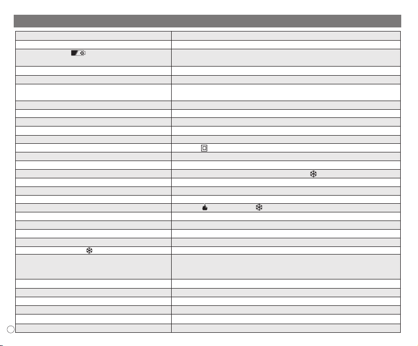
FACTORY SETTINGS TABLE (default)
Parameter
Language
Active season
Temperature unit of measure
Set t1 COMFORT Winter
Set t2 ECONOMY Winter
Set t antifreeze (Winter)T
Set t1 COMFORT Summer
Set t2 ECONOMY Summer
Temp. locks Winter
Temp. locks Summer
Temp. adjustment mode
Differential hysteresis
Modulating proportional
Modulating period
Room temp. correction
Room temp. correction
Anti-scale protection cycle
Display contrast
Display back-lighting
Remote Probe
External Input
User Password
Installer Password
Password reset code
Default
IT (Italian)
Winter
°C (celsius)
20.0°C
18.0°C
6.0°C
24.0°C
27.0°C
Disabled
Disabled
DIFF. ON/OFF
0.3°C
Prop (not active)
10 min. (not active)
0,0 °C
0,0 °C
Disabled
Level 6
Timed 6 sec.
(not active)
(not active)
none
none
0927
Restore «reset»
To confirm
Default
Last value
Default
Default
Default
Default
Default
Default
Default
Default
Default
Default
Default
Default
Default
Last value
Default
Default
Last value
Last value
Default
Default
Default
RESTORE «Installer RESET»
Restore manyfactory settings (default)
RESTORE brings the thermostat back to factory settings with the
exception of some items as shown in the table; to perform the
operation follow theinstr uctions inparagraph 11.13.
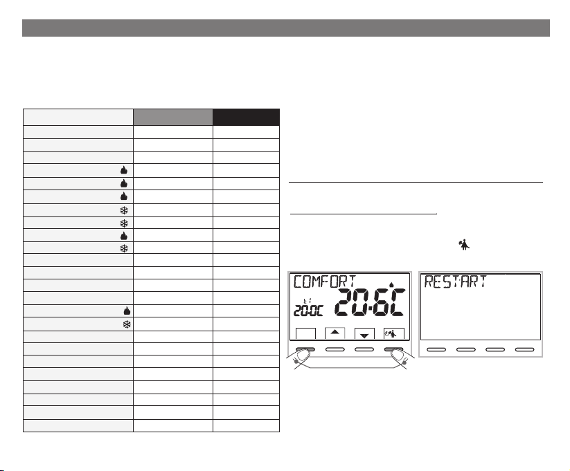
RESTART
It does not cancel the entered settings
Should thethermostat featuremalfunctioning, wrong displays or other
incorrect conditions,per form a .«User reset»
Simultaneously press for4 secs. the and keys.Menu
The thermostat resumesnormal operation.
Set
SetT
Menù
back
Press simultaneously for 4 seconds
Set
0
6810
2 4
SetT
Menù
back
12 14
161820
22
OK
5
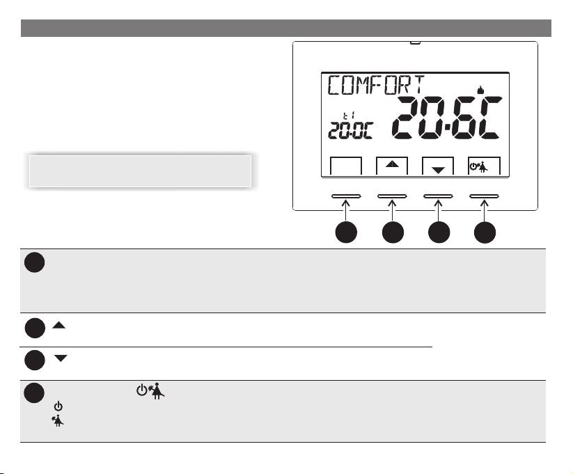
3 - KEY FUNCTIONS
Backlit display
Touching anykey activates back-lighting, displayingthe
words selection and navigation, press the desired key
within 6 sec. to vary the settings (touching any key
reactivates a 6secs. time-out).
Set
Note: more particularbutton functions aredescribed
in the specificparagraphs.
Multifunction Key Menu/back,
A
its use changes depending on function or active menu:
Menu = press briefly to switch temperature from comfort to economy and vice-versa,
press and hold (3 sec.) access to menus
back = exit from menusgo back to previous item,
B
C
D
6
increases the desired Set temperature;Key
navigation through the menus: to increase a setting value;
Key decreases the desired Set temperature;
navigation through the menus: to decrease a setting value;
Multifunction Key
thermostat in OFF (disabled temperature control)
current program pause for household cleaning
access to selected menu / confirm function or set value (within the menus)
OK
OK
Menù
back
SetT
A
OK
B
C
D
Press the pulse arrow key to
increase/decrease per unit
and keep pressed to
increase/decreaserapidly.
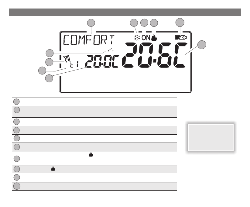
4 - DISPLAY FEATURES
5
4
3
Set
2
1
Display Set temperature
1
Currently active set temperature depending on the desired setting:
2
Comfort or Economy (saving) or antifreezet1 t2 t
Current program pause (example: for household cleaning)
3
Enabling thermostat from remote control
4
Info and thermostat operating mode, menu items
5
Cooling mode ( Summer) active
6
Signalling operating user = and flashingON
7
Signalling operating user = and flashingON
Heating mode ( Winter) active
8
8
Batteries low signal
9
8
Detected room temperature
10
T
T
T
(e.g. boiler on)
(e.g. conditioner on)
7
6
8
9
10
Note: further displays
are described in the
specific operation
paragraphs
7
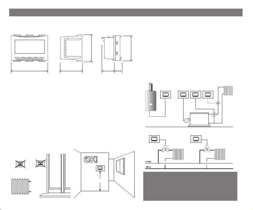
5 - INSTALLAZIONE
5 - INSTALLATION
5.1 - DIMENSIONS
47
3965 20 13
battery
thermostat module
5.2 - INSTALLATION REGULATIONS
The installation and electrical connection of the programmable
thermostat must be implemented by qualified electrician and inonly a
conformity with current laws and regulations.
declines allliability inconnection with theuse ofproducts subject to
special environmental and/orinstallation standards.
Thermostat installation: independent - fixed
recessed in rectangularbox 3 modules.
Install the thermostat at a height of 1.50 to 1. 0 m from the floor, far from7
sources of heat,windows and anything thatmay alter its operation.
The manufacturer
5.3 - INSTALLATION EXAMPLE
Warning: before installing, deactivate
the mains voltage of the device to be controlled.
Examples of installation in heating systems with a
thermostat that controls:
43,5
A) Wall mounted boiler
B) Burner or Circulation pump or Motorized solenoid valve
C) solenoid valveZone
(example for floor system or other)
N.B.: theexamples contained inthis documentation arein principle..
AB BB
C C
!
8
h 1,5 m
IMPORTANT: for the assembly procedure of
the thermostat with the chosen residential
plate, follow instructions contained in the
specific compatibility sheet contained in the
package.
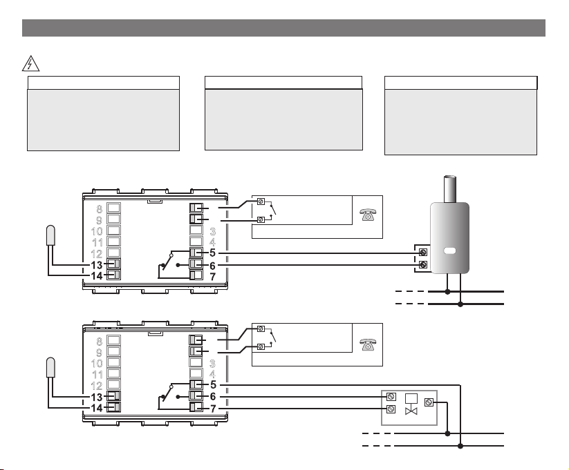
5 - INSTALLATION
5.4 - ELECTRICAL CONNECTIONS
Disconnect the 230V~ mains voltage that powers the devices to be controlled
Relay terminals
! connect the device to be controlled
to the terminals
5 - common (C)
- normally open contact (NO)6
- normally closed contact (NC)7
Examples of electrical connections
Separate
temperature
probe
(optional)
AUX 1
Separate
temperature
probe
(optional)
AUX 1
AUX 2
C
NC
AUX 2
C
NC
AUX 1 Terminals (remote probe)
! terminals may be connectedand13 14
to a separatetemperature probe
!(see paragraph 11.7to set the probe)
Note: maximum cable length 4 m
1
2
NO
example: Telephone programmer
1
2
NO
example: Telephone programmer
Contact for remote
thermostat control
Contact for remote
thermostat control
AUX 2 Terminals (remote contact)
! terminals may be connectedto12and
a telephone programmer (or switch)
for remote thermostat enabling (see
paragraph 11.8 for external contact
setting)
BOILER
(optional)
(optional)
opens
closes
LOAD
Connection
to a boiler
N
230V~
Connection to a
motorized valve
N
230V~
L
L
9
5 - INSTALLATION
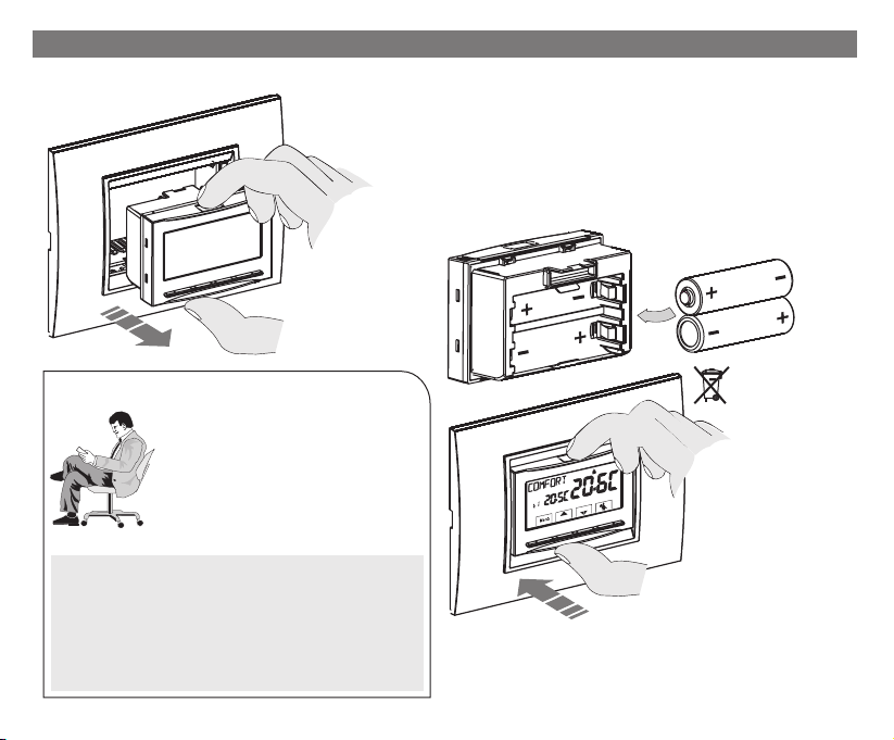
5.5 - THERMOSTAT REMOVAL AND INSERTION
Insert or replace with 2 1.5V AA-LR6batteries paying attention
to polarity.
ONLY USEGOOD QUALITY ALKALINE BATTERIES
(Duracell or Energizerbatteries are recommended)
Attention: batterylife may be morethan 2years.
However,it isrecommended toreplace themat leastevery 24 monthsto avoid
them runningout when you areaway (e.g. Christmas holidays,etc.)
1°
Remove the
thermostat module
by grasping it with
your fingers in the
appropriate seats.
(es. battery replacement, programming)
2°
ALKALINE
ALKALINE
Convenient programming
All setting operations may beperformed before
inserting the thermostat module to the
recessed base; this means setting may be
carried out while comfortably seated.
The flashing indication with fixed winter orON
summer symbol indicates that the thermostat
is detachedfrom therecessed base.
Attention!
If programming of the thermostat module takes place before fixing
to the recessed base, upon completing installation the ON
indication (off or flashing) on the display might not correspond to
the actual relay status.
Within 1 minuteat the mostthe insertion of the thermostat module
to the recessed base, the relay activateswith the indication (offON
or flashing) displayed.
10
Dispose of flat
batteries in
appropriate containers
and as required by the
environmental
protection regulations.
ON
Set
3°
Reinsert the thermostat
module fully into the
recessed base.
Important: if the display shows the message , itNO RELAY
indicates that the thermostat module has not been correctly
inserted all theway into therecessed relay base.

5 - INSTALLATION
5.6 - SIGNALLING BATTERIES LOW OR DOWN
When the symbol blinks,this indicatesthat thebatteries arer unning out and
as from thismoment there are 15days to replace them.
Note: the backlight of the display is automatically deactivated.
If the discharged batteries are not replaced within this time the display will
completely turn off.
All thermoregulation is suspended and all settings are saved to be restored when
the new batteriesare inserted.
Set
11

6 - START THE THERMOSTAT
5 - INSTALLAZIONE
Upon first insertion of the batteries, the thermostat performs a lamp-test by switching on all display segments, displaying the
installed softwareversion fora fewseconds.
When thisphase is over, thethermostat asks to selectthe languageof use.
Select the desired language by scrolling through
the available languagesusing the keys.
Set
0
6810
OK
2 4
12 14
161820
Confirm pressingthe key.OK
The selectable languagesare:
22
OK
ITALIAN ENGLISH FRENCH(default)=It , =En,
=, =Fr = dE, ES.GERMAN SPANISH
1°
2°
Press twice
Press 2 timethe key.back
the back key
Winter mode (heating)
ON + flashing = e.g. operating boiler
Set
The thermostat is operative, Winterdisplaying: «heating» mode, the temperature Set at 20°C COMFORT, room temperature
detected.
From normal thermostat operation in stand-by, pressing a key lights up the display (unless back-lighting has been disabled)
and the wordsselection andnavigation appear. Within 6secs., a variationis madethe second time thedesired key ispressed.
See use ofthe thermostatto the nextchapter.
12

7 - USE OF THE THERMOSTAT
7.1 - MODIFICATION of temperature from COMFORT to ECONOMY
(energy saving) and vice-versa
Press the MENU key briefly
WINTER= heating (factory setting)
With COMFORT temperature
Set Set
7.2 - MODIFICATION OF T TEMPERATURE SETSet
Directly press the keys.
IMPORTANT!
The thermostat allows temperature values that satisfy the following
conditions:
Set Set
Winter: t1 t2 tgreaterthan or equalto greater than or equalto
Summer: t2 t1greater than orequal to
In the presence of max and min. temperature locks (see
paragraph 11.6) it is not possible to seta higher or lowerSet t
than the entered locks. The display will signal impossibility to
perform the operation bydisplaying .
Every time the keys are pressed, it changes by 0.1 degrees;or
pressing and holding enables you to scroll through the values rapidly.
Range: +5 °C to +37,7°C (+41,0°F ÷ 99,9°F).
7.3 - TEMPERATURE CONTROL PAUSE (example for household cleaning)
Pressing the key connected user will switch off for a max 3hour period during which the thermostat will enter antifreeze
mode ( ).t
After 3hours the thermostat temperaturecontrol will resume.
It is possible to restar t temperature control before the 3 hours
have elapsed, press« »:the word disappears.back «CLEANING»
Note: in theevent antifreeze temperaturehas been permanently disabled
or in "Summer"operation, the connected user(e.g. boiler or airconditioner) will remain disabledfor 3 hours maximum.
Set
Set
OK
OK
13

7 - USE OF THE THERMOSTAT
7.4 - OFF (disabling the thermostat)
This settinghas the purposeof lockingthermostat functions
when heating orcooling must remain off.
1- In «CLEANING» mode, press the button briefly to
set the thermostat to and consequentlyOFF «Switch off
the system».
2- The display shows , to indicate thatthe thermostat is disabled andall functions are inactive; the
display only shows room temperature reading, the descaling function, if enabled and (in WINTER
mode) the temperatureSet plus the antifreezeprotection symbol .t
in WINTER mode with antifreeze temperature disabled or in Summer mode, the symbol will nott
be visible.
3- to reactivatethe thermostatPress key .
OFF
Set
OK
OK
8 - STRUCTURE OF THE MAIN MENUS (use and configuration)
The Menus are arranged in sequential order
User Menu:
1 SEASON (Winter or Summer mode)
2 SET TEMP
(modification or disabling of Set antifreeze temperature)
T
3 USER PASSWORD (set user password)
Installer or skilled user menu:
4 CONFIGUR
- LANGUAGE (selection of the desired language)
- RULE (selection of temperature control mode)
14
- UNIT (selection of temperature unit of measure °C/°F)
- OFFSET (correction of detected room temperature)
- BLOCKS (it lets you limit the value of set temperature points)
- PROBE (setting a remote temperature probe)
- INPUT (setting an external contact for remotely enabling / disabling
the programmable thermostat)
- PUMP ON (disabling / enabling the descaling function)
- CONTRAST (to change display contrast)
- BACKLIGHT (to enable/disable display backlighting)
- PASSWORD (to restrict the use of user and/or installer
- RESTORE (RESET operation)
functions of the thermostat)
- INFO SW (information about the firmware version installed)
OK
OK

9 - ACCESSO AI MENU
9 - ACCESS TO MENUS
From normal thermostatoperation, pressthe key for3 sec . toaccess the first availablemenu.Menu s
Or,if asecret user and/orinstaller access code , follow thesteps below to accessthe user or installermenus.has been previouslyentered
main screen
with the user and installer password
Set
for
3 sec .s
OK
with user password only
1°
password entry example
OK
no password entered
Set
0
2 4
The keysare used toscroll through themenus: press to enter the selectedmenu, press
6810
1°
12 14
161820
2°
22
OK
1°
the 1st user menu is accessed after
entering the user password
(see next paragraph)
OK back
OK
2°
to goback to the previous item.Settings inthe menus must be confirmedby pressing the key whereOK
required, otherwise,after 3minutes have elapsed,the thermostat goes backto normal stand-by operation
and changes willnot be saved.
OK
2°
is displayed
for a few seconds after
pressing the key to
OK
indicate incorrect
OK
password.
the 1st menuCONFIGUR
item is accessed after
entering the installer
password (see par 11.1)
Set
0
2 4
6810
12 14
161820
22
OK
15

10 - USER MENU
10.1 - SET WINTER OR SUMMER MODE
From normal thermostat operation,access the menus
by pressing andholding the « » key.Menu
Under item confirm with .SEASON SEt OK
Select with the keys the WINTER (heating) or
SUMMER (cooling) modeand confirm withOK.
Press the key to exit.«back»
10.2 - MODIFICATION OR DISABLING OF SET ANTIFREEZE TEMPERATURE
From normal thermostat operation, accessthe menus
by pressing andholding the « » key.Menu
Use the keys to select item .SET TEMP Set
Press to confirm.OK
The screen displays .ANTIFREEZE
Press to confirm.OK
Use the keys to set the desired antifreeze
temperature.
Every time the keys are pressed, it changes by 0.1 degrees;or
pressing and holding enables you to scroll through the values rapidly.
Range: +5 °C a +12°C
Todisable antifreeze temperature t , go below+5.0 °C .(41.0°F)
Set
Confirm with Press the key to exit.OK. «back»
16
Set
disabled antifreeze temperature
T
Set
0
6810
Set
0
6810
2 4
0
6810
2 4
12 14
12 14
161820
161820
22
OK
22
OK
2 4
Set
0
6810
2 4
Set
0
6810
2 4
Set
0
6810
2 4
1°
12 14
12 14
12 14
12 14
161820
161820
161820
161820
2°
OK
OK
OK
OK
22
22
22
22

10 - USER MENU
10.3 - USER PASSWORD Menu
10.3.1 - Entering the user password
No code is set in the factory configuration.
From normal thermostat operation,
menus by pressingand holding the « » key.Menu
1- Select item with the keysUSER PASSWORD Set
and confirm with .OK
2- Use the , keys enter 4 digits (dashes not
included) between and , individually0000 9999
confirm themwith «OK».
access the
Set
0
2 4
6810
12 14
161820
22
OK
The thermostat entersnormal operation.
From now on, the password will be required for any
variation on thethermostat.
Set
0
6810
2 4
1°
10.3.2 - Password modification or cancellation
Press and enter the previously set password; follow the procedureMENU for 3 secs.,
described above toaccess the menu:User PASSWORD SEt
- set 4hyphens (- -- -), the passwordwill becancelled,
- set anothernumber and itwill be modified.
12 14
161820
2°
Set
0
6810
2 4
22
OK
1°
12 14
161820
2°
22
OK
password entry example
Set
0
2 4
6810
12 14
161820
22
OK
17

11 - ACCESS TO CONFIGURATION MENU (installer)
11.1 -
ACCESS TO CONFIGURATION MENU
ATTENTION: access to the configuration menu is recommended since thefor the installer or experienced users
modification of some settings might affect correct systemoperation.
From normal thermostat operation, access the menus by
pressing and holdingthe « »key.Menu
Select with the keys the item andCONFIGUR Set
confirm with access the 1st item ofOK: LANGUAGE SEt
the menu (see chapter 8 the list of sub-menus to the item
CONFIGUR).
If onlyan installer passwordwas entered
the display requests entering the 4 digits,
which may be selected using the ;
keys; individually confirmthem with«OK».
11.2 - CHANGE SET LANGUAGE
When is displayed, press to confirm.LANGUAGE SEt OK
•Use the keys to select the desired language
scrolling through availableones.
•Confirm bypressing OK.
The selectable languagesare:
ITALIAN ENGLISH FRENCH GERMAN SPANISH(default) = , ==It , = En, Fr = dE, ES.
•Press the « » keyto exit.back
Set
0
2 4
6810
12 14
161820
22
OK
Set
0
6810
2 4
12 14
1°
Set
0
2 4
6810
12 14
161820
22
OK
Set
0
6810
2 4
12 14
1°
161820
2°
161820
2°
22
OK
22
OK
18

11 - ACCESS TO CONFIGURATION MENU (installer)
11.3 - TYPE TEMPERATURE ADJUSTMENT METHODS
The thermostatis factoryset towork in modeTHERMAL DIFFERENTIAL
ON/OFF with apreset thermal differentialvalue (Hysteresis)of 0,3°C.
Note: adjustable from0,2 °C to 1,2°C (from 0,3 °Fto 2,1 °F).
The hysteresis value must be set according to the system's thermal
inertia; a low valueis recommended forsystems with radiatorsmade of
°C/°F
T SET
hysteresis
OFF
e.g. cast ironand a high valuefor systems with fancoils.
As opposed to the thermal differential, the temperature can be adjusted
example of differential adjustment
MODULATING PROPORTIONALLY (PROP) setting cycles from 7 to 20
minutes (default 10minutes).
This system maintains the desired temperature more stable, whilst
increasing the user's comfor t sensation and saving on energy
consumption.
°C/°F
T SET
OFF
A longcycle is recommended forsystems with high thermalinertia (cast
iron radiators, floor systems) and a short cycle for systems with low
thermal inertia (fan coils).
example of modulating proportional adjustment
11.3.1 - SELECTION OF THE TEMPERATURE ADJUSTMENT MODE (DIFFERENTIAL ON/OFF OR PROPORTIONAL)
From normal thermostatoperation, accessthe menusby pressing andholding the « » key, select press to confirm.Menu OKCONFIGUR Set,
With thekeys select laitem RULE Set.
Press to confirm.OK
It will be possible to select temperature adjustment mode
between factory setting orThermal differential (On:OFF)
Modulating proportional(PrOP) operation.
Use the
keys to select the desired temperature adjustment
mode. After making your choice press to confirm and displayOK
the screen to set if you have opted for or toHYSTERESIS On:OFF,
set the if you have opted for (see next paragraphs:PERIOD PrOP
11.3.2 and11.3.3).
Set
0
2 4
6810
12 14
161820
thermal inertia over temperature
of the heating element
ON
ON
OFF
thermal inertia over temperature
of the heating element
ON OFF
OFF
22
OK
Set
0
2 4
ON
6810
Set
0
time
ON
time
161820
12 14
22
OK
6810
161820
12 14
2 4
22
OK
19

11 - ACCESS TO CONFIGURATION MENU (installer)
11.3.2 -Setting hysteresis for thermal differential ON-OFF
From normal thermostatoperation, accessthe menusby pressing andholding the « » key.Menu
•Through the path then press .CONFIGUR SEt ->RULE SEt -> On:OFselect , OK
•With the keys enter the desiredhysteresis value
(values may beset from 0.2 °Cto 1.2 °C /from 0.3 °F to2.1 °F- default0.3 °C/0.4°F).
•Press to confirm.OK
•Pressthe keytoexit.back
Set
0
2 4
OK
10
161820
12 14
8
6
22
Set
0
2 4
6810
12 14
161820
22
OK
11.3.3 - Setting period duration for modulating Proportional
Dal normale funzionamentodel termostato,accedere aimenu tenendopremuto tasto« ».Menu
•Through the path thenpress .CONFIGURSEt -> RULE SEt-> PrOP,select OK
•With the keys enter theduration of thedesired period
(settable from 7to 20 minutes, default10 min.).
Set
0
2 4
OK
•Press to confirm.OK
•Press the key toexit.back
11.4 - CHANGE UNIT OF MEASURE FOR TEMPERATURE READING
The thermostat is pre-set in the factory to display temperatures in degrees Centigrade (Celsius), it is
possible to switchto the Fahrenheit scaleor viceversa withthe followingprocedure:
From normal thermostatoperation, accessthe menusby pressing andholding the « » key.Menu
•Through the path then press .CONFIGURSEt -> UNIT SEtselect OK
•Select the desiredunit of measure withthe keys: °C or °F,
then press to confirm.
All temperature setpoints will be updatedaccording to the newscale.
•Press the key toexit.
20
OK
back
OK
Set
12 14
12 14
2°
161820
2°
161820
22
OK
22
OK
1°
10
8
6
SetSet
0
6810
2 4
1°
Set
0
6810
2 4
OK
Set

11 - ACCESS TO CONFIGURATION MENU (installer)
11.5 - CORRECTION OF ROOM TEMPERATURE READING
If for any reason the thermostat must beinstalled in a position where the measured
room temperaturemight be affected(e.g. perimeter wallwhich is onaverage colder
in winter and warmer in summer than the rest of the dwelling) the device has 2
separate parameters to adjust the room temperature measured in the andWinter
Summer modes.
From normal thermostat operation, access the menus by pressing and holding the « » key.Menu
• Through thepath CONFIGUR SEt -> OFFSET Set.select item
Press to confirm.OK
OFFSET for winter mode ()
The display alternates the empty fields to be inser ted ( ) with the current---temperature value.
•Use the key to enter positivevalues, the key toenter negative values (sign«-»).
Possible correction -3.0°C ÷ 3.0°C(-5.4 °F) (5.4 °F)
default 0.0 °C/°F=
----
At each selection the displaywill show the new correctionvalue (e.g.: 0.6°C) alternated
to the detectedtemperature value (e.g.: 21.2°C).
•After performing thecorrection press «OK».
The displayshows the ( ); proceed withthe correctionOFFSET forthe Summermode
as per theabove procedure or press to quit.back
to cancelany previously settemperature correctionstake OFFSET
back to .
11.6 - MAX AND MIN SET TEMPERATURE LOCK (Winter and Summer mode)
In certain thermostat installations (public buildings, hotels, etc.) it might be useful to limit the maximum and minimum temperature set points.
This avoids incorrectsettings by unauthorised personnel(energy savings).
It ispossible to limit(lock) themaximum, minimum orboth temperature valuessettable onthe thermostat.
The restrictionmay be appliedeither tothe or mode.Winter Summer
SetSet
0
2 4
6810
Set
12 14
Set
161820
22
OK
OK
OK
Set
Set
21

11 - ACCESS TO CONFIGURATION MENU (installer)
11 - MENU PER LA CONFIGURAZIONE (installatore)
From normal thermostatoperation,
access the menusby pressing and holdingthe « »key.Menu
•Through the path , select item . Press to confirm.CONFIGUR SEt -> LOCKS SEt OK
In asequential manner itis possible toset maximumtemperature locks and/or minimum( ) for the and/or(t1 comfort) t2 economy winter mode
maximum temperature and/or minimum ( ) for the .(t1 comfort) t2 economy Summer mode
If no lockshave been entered yet,the display shows emptyflashing fields ( ).----
•Use the ,
keys to setthe desired temperature lockvalues from time totime.
•Upon completing eachsetting press to confirmand move tothe next lock item.OK
Press the impulse keyto moveto adifferent item. Pressthe key toexit.OK back
Set
0
2 4
6810
12 14
161820
22
OK
Set
Set
Set
OK
To cancel any previously set locks bring the
MAX/MIN setpoints back to .
Set
Set
OK
General rule
If (comfort) is , it willlevel out with it.Set temperature t1 greater than themaximum entered lock
If is , it willlevel out with it.Set temperature t or t2 less thanthe minimumentered lock
The following rule will applyto all other temperatures:WINTER ( ) = > > - SUMMER ( ) = <t1 t2 t t1 t2
During thermostat operation,the usermay notset a higher orlower thanthe maxand min. locksentered.Set t
The display willsignal impossibility to perform theoperation bydisplaying .
22
OK
OK

11 - ACCESS TO CONFIGURATION MENU (installer)
11.7 - PROBE MENU
In addition to the internal probe of the thermostat, it is possible to connect to terminals and « (see wiring diagrams in ch. 5.4) a13 14 AUX 1»
supplementary probe(optional) which may beset to read temperaturein various modes.
•Press for3 secs. the key press . Selectablefunctions are asfollows:Menu OK,-> ->CONFIGUR SEt PROBESet
PROBE NO
REMOTE PROBE
FLOOR PROBE
EXTERNAL PROBE
Select the desired type of probe with the keys and confirm with OK.
The separate probe is not read, it is disabled (factory setting upon first witch on).
It measures the temperature of a room in replacement to the internal probe of the thermostat.
It measures the floor temperature and switches off the connected load if it exceeds a certain set threshold.
Room temperature control is managed by the internal thermostat probe.
It measures the temperature outside the home without affecting internal room temperature control.
12 14
Set
0
6810
2 4
18
20
16
22
OK
12 14
161820
Set
0
6810
161820
2 4
Set
0
6810
2 4
12 14
161820
22
OK
12 14
22
OK
Set
0
6810
2 4
Possible fault signals on the display concerning the separate probe
4 flashing hyphens = thermostat removed from the wall base
Err flashing = interrupted probe or in short or no probe connected. Temperature control is suspended.
Flashing beginning or end of scale value = the probe detects a higher or lower value than the operating range.
11.7.1 - NO CONNECTION TO SEPARATE PROBE
Should you wish to disable the previously active separate temperature probe and go back to using the
standard internal one (default), follow this procedure: key down for 3 secs. and through pathMenu ->
CONFIGUR SEt ->PROBE SEt -> selectitem (NO) andpress toconfirm.PROBE nO OK
Press the key toexit.back
Internal probe reading range: - 5.0°C +37.7°C (+ 23.0°F +99.9°F)÷÷
22
OK
Set
0
6810
2 4
Set
0
2 4
6810
12 14
12 14
161820
OK
161820
22
22
OK
23

11 - ACCESS TO CONFIGURATION MENU (installer)
11.7.2 - SETTING SEPARATE REMOTE PROBE
This is a remote probe to detect temperature in a different room from the one where the thermostat is
installed, for instance in the event of unfavourable installation or in premises unsuitable to reading and
adjusting the temperature. The remote probe has the same parameters and reading range as the internal
probe. Reading range:-5.0°C÷+37,7°C (+23°F÷+99,9°F).
It completely replacesthe internal thermostat probe andthe product will controlroom temperature through
this remote probe.
After connecting the remote temperature probe to the thermostat, it may be activated through the path:
Menu -> REMOTEkey for 3 secs. select item .CONFIGURSet -> PROBE SEt->
«OK»
Press to confirm.
Press the key toexit.back
11.7.3 - SETTING FLOOR PROBE (over temperature protection function)
This isa separateand remotecontrollable temperature probe, buriedin the screed ofan underfloorheating
system with radiating panels, to monitor the temperature and turn off thesystem in casethe temperature
read exceeds apre-set threshold value.
After connecting the separate temperature probe to the thermostat, it may be activated holding down the
Menu -> FLOOR.key for 3secs. select itemCONFIGUR SEt ->PROBE SEt ->
Confirm withthe key.
Use the , keysto define the desiredtemperature (e.g. 35°C)threshold
Press to confirm.Press the key toexit.
Floor probe reading range: + 0.0°C +60.0°C (+ 32.0°F +140.0°F)÷÷
The thermostat displaysand controls the roomtemperature detected by theinternal probe:
at thesame time the separateprobe alsodetects the floortemperature, which will becompared with
the threshold setby the installer,to prevent this temperaturefrom exceeding the safetythreshold.
Should thisoccur thethermostat willswitch offthe systemeven if temperature isnot reached;Set t
the display signalsthis condition by displayingthe code and theset thresholdvalue flashes.tP
24
OK
OK back
Exceeding the 99.9°F value (Fahrenheit scale) involves suppressing decimals
Set threshold exceeded warning. The temperature control system is disabled.
Set
0
6810
2 4
Set
Set
0
6810
2 4
Set
0
6810
2 4
1°
Set
0
12 14
12 14
12 14
16
161820
161820
2°
18
20
22
OK
OK
22
OK
22
OK
OK

11 - ACCESS TO CONFIGURATION MENU (installer)
11.7.4 - SETTING SEPARATE EXTERNAL PROBE
This is anadditional probe to readthe temperature outside thedwelling ( ).tE
It does not have any home temperature control features, which are controlled by the internal thermostat
probe.
After connecting the external temperature probe to the thermostat, it may be activated by pressing the
Menu EXTERNAL.key for 3secs. and through thepath -> ->select itemCONFIGUR SEt PROBESet
«OK» back
Press to confirm.Press the key to exit.
External probe reading range: - 9.9°C +60.0°C (+ 14.2°F +140.0°F).÷÷
Exceeding the 99.9°F value (Fahrenheit scale) involves suppressing decimals.
Note: in normal thermostat operation, the display will alternate reading externaltemperature ()tE
with the currentlySet temperature value every 10 seconds.
every 10 secs.
11.8 - CONNECTION TO EXTERNAL CONTACT FOR REMOTE
THERMOSTAT SWITCHING ON/OFF
Before enabling any item of the «INPUT» menu listed below ensure you have connected an
external contactto terminals 1 and2 (AUX2).
A remote device may beconnected to the thermostat (e.g.telephone programmer, hourly switch, switch)
able to remotelyenable/disable the thermostat.
From normal thermostat operation,
and through the path select item .CONFIGUR SEt->, INPUT SEt
Press to confirm.
OK
Various operation modesmay beselected dependingon thetype ofcontact free frompotential (NOor NC)
and type ofdevice connected to theterminals « » (see par. 5.4electrical connections):1 2 AUX 2and
- = Input exclusion (factory setting);INPUT nO
- = for «Normally Closed» contact of a telephone Programmer;PHONE nC
- PHONE nA = for «Normally Open» contact of a telephone Programmer;
- = for «Normally Open» contact e.g.: switch;DUTY nA
- = for «Normally Closed» contact e.g.: switch.DUTY nC
access the menusby pressing and holding the key for 3 secs. « »Menu
Set
0
6810
2 4
Set
Set
0
6810
2 4
Set
0
6810
2 4
Note: to exclude the previously enabled input,
select the above screen with the keys,
confirming with the key.
Press to exit.
back
12 14
12 14
12 14
161820
161820
161820
OK
22
OK
OK
22
OK
22
OK
25

11 - ACCESS TO CONFIGURATION MENU (installer)
11.8.1 - ACTIVATION / DISABLING WITH A TELEPHONE PROGRAMMER
After connecting theTelephone programmer (optional)to the thermostat , it will be possible toselect the NA (normally openor other control device
contact) or NC(normally closedcontact contact typesetting on the telephoneprogrammer.
Press the key for 3secs. and throughthe path press and with keys choose itemMenu CONFIGUR SEt -> INPUT SEt,display item «OK»
PHONE nC PHONE nA «OK» backor . Press to confirm. Pressthe key to exit.
Set
0
6810
2 4
0
2 4
6810
12 14
12 14
161820
161820
11.8.1a - Example of remote thermostat switching
on/off, connected to a telephone
programmer with «nA» contact (NO
normally open).
- (change ofstate): and displaying thesteady icon indicatingProgrammer contactclosure causes temperature t1COMFORT override “”
incoming telephone override.
After that it will be possible to change the operation mode on the spot by manually acting on the thermostat keypad, even if the telephone
programmer contact remainsclosed; the icon “ ” it will remainon (steady),indicating thatthe contactis stillclosed.
- (change ofstate): (par.7.4 - Thermostat disabling) with antifreezefunctionProgrammer contactopening causes operationstatus override OFF
unless it isdisabled; thedisplay shows (steady)and icon“ ” flashing, indicating incoming telephoneoverride. Afterthat itwill bepossibleOFF
to go backto normal thermostatoperation by pressing the key ,the icon “ ” will go outindicating the end oftelephone override.
Note: contact opening and closure controls are operative within 10 secs.
26
)
e.g. Telephone programmer (NC contact)
22
OK
Contact closure
Contact opening
in WINTER mode with antifreeze temperature disabled or in Summer mode, the symbolt
will not be visible.
e.g. Telephone programmer (NO contact)
22
OK
Contact closure
Contact opening
Note: contact opening and closure controls are operative within 10 secs.
Set
Thermostat operation
in mode withOFF t antifreeze
in modet1 COMFORT
Thermostat operation
in modet1 COMFORT
in mode withOFF t antifreeze
E.g. Telephone programmer
NO contact

11 - ACCESS TO CONFIGURATION MENU (installer)
11.8.2 - «nA» DUTY - for normally open contact (NO)
By selecting this function it is possible to connect a NO remote contact which upon closing sets the thermostat in the mode with antifreezeOFF
temperature t , unlessit hasbeen previouslydisabled.
In this conditionit toact onthe thermostat keysto change operationstatus.will not bepossible
Open the contactand the thermostat .resumes operation modeactive before overriding
Press the key for 3sec ., follow thepath select item .Menu nA DUTYs CONFIGUR SEt ->INPUT SEt->
Press to confirm. .«OK» Press the key toexitback
Set
0
6810
2 4
12 14
161820
22
OK
Contact closure
Contact opening
e.g. Switch
Thermostat operation
in mode withOFF antifreezet
operation mode in progress
in WINTER mode with antifreeze temperature disabled or in Summer mode, the symbol will not be visible.t
Note: contact opening and closure controls are operative within 10 sec .s
11.8.3 - «nC» DUTY - for normally closed contact (NC)
Attention OFF: do not enable thenC DUTY item prior to connecting a switchor other device that allowschange of statefrom mode to operation
mode in progressand vice versa toterminals and (AUX 2).12
By selecting this function it is possible to connect a NC remote contact which upon opening sets the thermostat in the mode withOFF
antifreeze temperature t , unless it has been previously disabled.
In this conditionit toact onthe thermostat keysto change operationstatus.will not bepossible
Close the contactand the thermostat resumesoperation mode activebefore overriding.
Press the key for 3sec ., follow thepath select item .Menu nC DUTYs CONFIGUR SEt ->INPUT SEt->
Press to confirm. .«OK» Press the key to exitback
Set
0
6810
2 4
12 14
161820
22
OK
Contact closure
Contact opening
in WINTER mode with antifreeze temperature disabled or in Summer mode, the symbol will not be visible.t .
Note: contact opening and closure controls are operative within 10 sec .s
e.g. Switch
Thermostat operation
operation mode in progress
in mode withOFF antifreezet
27

11 - ACCESS TO CONFIGURATION MENU (installer)
11.9 - DESCALING CYCLE
If the function is activated, the programmable thermostat activates every
day ofthe year (24haf ter thelast intervention of therelay), for2 minutes.It
activates the controlled device (pump, valve etc.) to prevent scaling or
jamming caused byprolonged inactivity.
The thermostat activates only if the connected load was never
switched on inthe previous 24 hours.
From normal thermostat operation, press the key for 3 secs. followMenu ,
the path press and with theCONFIGUR SEt -> PUMP ON SEt -> «OK»
keys select thedesired item:
PUMP ON nO PUMP ON2'(NO) or .
Press toconfirm. Pressthe key toexit.«OK» back
11.10 - DISPLAY CONTRAST ADJUSTMENT
8 adjustment levels are available. Level 6 is set in the factory.
From normal thermostat operation, press the key for 3 secs. follow theMenu ,
path ->useCONFIGUR SEt
keys to selectitem .CONTRASTSet
Press to confirm.OK
Select the desired level with the keys.
The contrast variation obtained will be visible at every selection.
Press to confirm. Press the key to exit.OK back
11.11 - BACKLIGHTING
It lets you enable or disable timed display backlighting. From the normal
operate of the thermostat press the key for 3 secs., follow the pathMenu
CONFIGUR SEt ->use
Press to confirmOK .
With the keys select the desired item: timed backlighting or6secs.
disabled backlighting (NO).nO
Press to confirm. Pressthe key toexit.OK back
Factory setting: timed backlighting 6 secs.
28
keys to selectitem .BACKLIGHTINGSet
Set
0
2 4
OK
Set
6810
Set
0
2 4
OK
12 14
Set
0
6810
1°
Set
2 4
161820
6810
22
OK
12 14
Set
0
6810
2 4
161820
12 14
OK
Factory setting upon first
switching on the function
is disabled.
Set
0
6810
2 4
161820
22
OK
2°
Set
0
6810
2 4
back
161820
12 14
22
12 14
161820
22
OK
22
OK
OK
161820
12 14
22
OK
OK

11 - ACCESS TO CONFIGURATION MENU (installer)
11.12 - ENTERING AND MANAGING PASSWORDS
Some functions of the thermostat may be protected by a user Password (Ut)
and/or installer , sothat theymay be only modifiedby authorisedpersons. No(Inst)
password is activein factory settings.
11.12.1 - ENTERING THE NEWPASSWORD
•From normal thermostat operation,press the key for3 secs. andfollow theMenu
path press to access thescreen toCONFIGUR Set-> PASSWORDSEt -> «OK»
create a secret code ( confirm with , or select itemUser OKPASSWORD SEt Ut),
PASSWORD SEt InSt with the keys and confirm with to create theOK
Installer code.
•Using the , keys enter 4 digits (dashes not included) between and0000
9999 «OK», individually confirmthem with .
Press the key to exit.back
The password lets youaccess available functions throughthe key.«User» Menu
If an installer password is also present the menu may not beCONFIGUR SEt
accessed.
The password lets you access all«Installer» «Configurations» (CONFIGUR
SEt) Usermenu functions as well as settings.
0
2 4
example:
6810
OK
12 14
161820
Set
0
OK
2 4
OK
OK
22
6810
enter the user password as
161820
12 14
an example to the side
22
OK
OK
11.12.2 - PASSWORD MODIFICATION OR CANCELLATION
When required, enterthe previously created Useror Installer password;
OK
follow the aboveprocedure and access item or :PASSWORDSEt Ut InSt
- enter 4hyphens (- -- -) to cancelthe password
- enter 4new digits tomodify the password
Information reserved to installer or expert user only
in the event of forgottenpassword enter thereset code when useror installer access is requested.
The secret user or installer code will be cancelled.
OK
OK
OK
29

11 - ACCESS TO CONFIGURATION MENU (installer)
11.13 - RESTORE (RESET)
IMPORTANT! The RESTORE (Reset) operation is recommended for the
installer or expert user. In fact, this operation deletes many previous
settings carriedout alsoaccording to thetype ofsystem.
•The operation may be carried out pressing the key for 3 secs., follow the pathMenu
CONFIGUR Set -> RESTORE SEt:OKusing keys select item confirm with .
The display willask to choose betweenrestore and .«YES» «NO»
•Use the keys, toselect thenpress to confirm.OK
•If you opt for the display exits the function and goes back to the initialNO RESTORE SEt
screen. Press the key to exit.back
•If you confirm will bedisplayed for3 seconds,then thesystem willrestartYES «RESTORE»
and display thelanguage screen.
• Use the keys to select the scrolling throughavailable ones.desiredlanguage
• Confirm bypressing Press 2 timesthe key toexit.OK. back
•The thermostat entersnormal operation.
Note: the thermostat restores many factor y settings (default) with the exception of some
special items thatuse the last setvalue (see summary tablein chapter2).
The RESTOREoperation deletes anyuser and/or installer password entered.
OK
Set
0
6810
2 4
12 14
161820
22
OK
OK
OK
Set
0
6810
2 4
12 14
161820
22
OK
11.14 - SYSTEM SOFTWARE INFORMATION
From normalthermostat operation, pressing for 3 secs. the key and follow the pathMenu
CONFIGUR SEt INFO SW->, use to obtaininformation about
the installed firmware.
Press the key toreturn to the previousmenu or press to exit the menu.back OK
This information isuseful inthe eventof request fortechnical support.
30
keys to select item
Firmware version
Example:
Set
0
2 4
6810
Firmware revision
161820
12 14
22
OK
OK

12 - POSSIBLE PROBLEMS AND SOLUTIONS
PROBLEM
The thermostat display is OFF
The display flashes the
Batteries not installed
Wrong battery polarity
Dead batteries
The batteries are running low
CAUSE
SOLUTION
Check that the batteries are installed
Check polarity of batteries
Replace the batteries
Replace the batteries within 15 days
symbol
The display only shows a steady
symbol
Display of theinscription: NO RELAY
The batteries are dead
The thermostat module has not
been fullyinserted into the recessed
relay base.
No power to the system
The thermostat works but the system
does not start
The temperature fluctuates too much
between hot and cold
Iin OFF operation (Winter ), the Set
antifreeze temperature is not
displayed
DISPOSAL OFOLD ELECTRICALAND ELECTRONIC EQUIPMENT
When thissymbol isfound on theproduct oron its packaging,it indicatesthat this productcannot bedisposed of ashousehold waste.
It mustbe deliveredto a specificcollection pointwhere electrical andelectronic equipmentis recycled, suchas:
- retailoutlets, ifa new productis bought,similar to thatbeing disposedof
- localcollection points(waste collection centres,local recyclingcentres, etc).
By ensuringthat theproduct isdisposed ofcorrectly,you will helpprevent potential negative consequencesfor theenvironment andhealth, whichcan becaused by
this productbeing disposedof inappropriately.
Recycling thematerials willhelp conserve naturalresources.
For moredetailed information aboutrecycling this product,please contact yourLocal Council, householdwaste disposal service orthe shop whereyou purchased
the product.
The thermostat is not connected
properly
The thermostat is not set correctly
for the typeof system
The antifreeze temperature has
been excluded
Replace the batteries
Extract andreinsert thethermostat module
fully into the recessed relay base as
indicated in paragraph5.5.
Make sure the switch or differential
protection device is not set to OFF
Contact the installer
Contact the installer
Set theantifreeze temperatureby following
the instructions inparagraph 10.2
31

 Loading...