

PE - DETIPE016EN 11/19
ENGLISH
PERRY ELECTRIC Srl
Via Milanese, 11 - 22070 VENIANO (CO) ITALY
www.perry.it
RECESS ELECTRONIC THERMOSTAT
Models with LCD DISPLAY,
differential ON/OFF intervention and luminous charge inserted signal
Ins allationt
and user
in tructionss
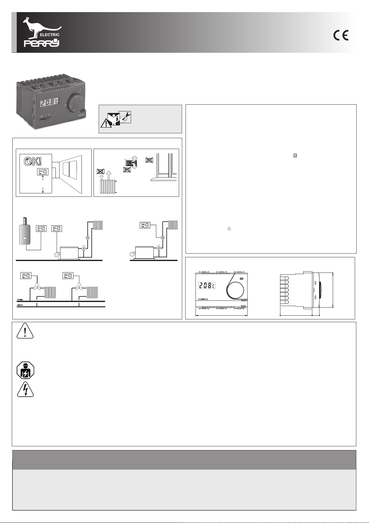
INSTALLATION EXAMPLES
5
101
0
1515
0
303
20
2525
5
101
0
1515
0
303
20
5
1010
5
151
3030
2020
2525
5
1010
1515
3030
20
2525
h 1,5 m
Install the thermostat at a height of 1,5 m ÷ 1,7 m from the floor, far from heat00
sources, air vents, doors or windows and anything else that could affect its operation.
B
A
5
5
1010
1010
1515
1515
3030
3030
20
2020
2525
2525
2525
5
101
0
1515
3030
2020
2525
C
Series MODULE - H 45 mm
TECHNICAL DATA
DATI TECNICI
Supply voltage:
Type of action, disconnect and device:
Output connection (load):
Inputs for remote "Reduction” control:
Wire section at terminals:
Insulation type:
Protection degree:
Pollution:
Operating temperature limits:
Storage temperature limits:
Temperature adjustment range:
Antifreeze temperature:
Temperature display scale:
R ion temperature:educt
(remote control)
Precision of readingtemperature :
Room temperature indicator resolution:
Differential operation - selectable:
ERP Energy classification:
Thermal gradient:
Reference standard for CE mark:
:Type of output
t
230 V~ 50 ÷ 60 Hz
1/ B / Electronic
relay with changeover contact
NO / COM / NC - voltage free
max 8(2)A / 250 V~
2 or 3 conductors
for potential-free contact
min. 0,75 mm ÷ max. 2,5 mm
Class II
I30P
Normal
0 °C ÷ +50 °C
-10 °C ÷ +65 °C
22
+5 °C ÷ +30 °C (limitable)
+5 °C fixed
- 5 °C ÷ +39 °C
- 4 °C from the set temperature
("Winter" operation)
+4 °C from the set temperature
(“ ” operation)Summer
± 0,5 °C
0,1 °C
0,3 °C - 0,5 °C - 0,7 °C - 0,9 °C
ErP: Class I; 1% Reg. EU 811/2013
1 °K/15 min
LVD EN60730-2-9
EMC EN60730-2-9
D
5
1010
5
151
3030
20
2525
D
5
1010
5
151
30
2020
2525
Heating systems with a thermostat
DIMENSIONS
that controls:
A)
Wall mounted boiler
BurnerB)
45
Circulation pumpC)
Zone solenoid valveD)
N.B.: the examples contained in this documentation are in principle.
66
40 9
SAFETY PRECAUTIONS!
Read this manual carefully before using the product as it provides important guidelines regarding safety, installation
&
The thermostat is not intended for use by persons (including children) with reduced physical, sensory or mental capabilities,
or by those with a lack of experience and knowledge of the instructions, unless they are supervised or have received the
necessary instructions concerninguse of the device by aperson responsible for their safety.
Children should be supervised to ensure that they do not play with the device.
If necessary, gently clean the thermostatand the displayusing a soft, dry cloth.
The manufacturer reserves the right to introduce any technical and/or constructive changes deemed necessary, with no prior notice.
and use. Themanual must be preserved with carefor future reference.
Important: installation and electrical connections of devices and appliances must be carried out by skilled people
and in compliancewith current regulations
Before starting any operations on the device, disconnect the 230V~ mains power supply
COMPATIBILITY TO THE MOST COMMON RESIDENTIAL SERIES PLATES
IMPORTANT: for the assembly procedure of the thermostat with the chosen
residential plate, follow instructions contained in the specific compatibility
sheet contained in the package.
SIGNALS AND CONTROLS
Load status LED
Temperature display
(alight LED = load inserted)
- Display of room temperature
- Display of temperature being set
The display normally shows thedetected room temperature. Whensetting the
Temperature setting knob
temperature withthe knob, the display showsthe temperature being set. Afew
seconds after the operation, the display goes back totheroomtemperature.
In mode, the displayed temperature being set is the reduced“Reduction”
Reference index for temperature setting
temperature:
-4 °C from the temperature setpoint (for model with )On - Off - Antifreeze
-4 °C in “ ” +4 °C in “ ” (Winter Summerand for model with Winter - Off -
Summer)
Flashing indications
-5.0 °c 39.0 °c
or
- - -
= “faulty probe” (the relay is deactivated)
= “room temperature out of display range”
Temperature control
Selector for controlling work mode (according to model)
Model: 1TITE312/MC
0
activated
Temperature control
disabled
Anti-freeze
operation
Operation
Winter
(Heating)
Model: 1TITE313/MC
0
Temperature control
disabled
Operation
Summer
(Cooling)
INSTALLATION INSTRUCTIONS
Important: t only a electricianhe installation and electrical connection of the programmable thermostat must be implemented by qualified and in conformity with current laws and
regulations.
Warning: before making the product setting, switch off the mains voltage.
The manufacturer declines all liability in connection with the use of products subject to special environmental and/or installation standards.
1-INSTALLATION EXAMPLE
COMPATIBILITY TO THE MOST COMMON RESIDENTIAL SERIES PLATES
IMPORTANT: for the assembly procedure of the thermostat with the
chosen residential plate, also follow instructions contained in the
specific compatibility sheet contained in the package.
Thermostat body
Fasten the chosen frame
to the type 503 recess box
Front
AB C D
Apply the chosen front
(4 lateral blocking teeth)
IMPORTANT!
30
25
5
5
20
10
15
Correct positionknob
Insert the knob
2 - CHANGING THE DIFFERENTIAL VALUE
The thermostat operates in differential mode (ON-OFF) with the differential value that can be edited
(preset by default to 0.5°C).
Differential valuemodification:using the tip of asmall screwdriver,set the dip-switcheson the thermostat
(below the front panel) to the desired value, asindicatedinfigure1.
Make the electrical connections
30
25
20
10
15
Left ledge
Insert the thermostat into
the frame until itis blocked
Attention to the position of the
insertion pins of the ledges
30
25
5
20
10
15
F
Apply the two ledges to the frame
(if required based on the plate type)
Right ledge
fig. 1
Set temperature lock
(only if desired)
30
25
5
20
10
15
GFE
Apply the chosen plate
Range disc
Plate
Important: changing the differential value allows you do optimise
the temperature control of the system.
This must be performed by expert personnel (electrician, plumber).
ATTENTION: if the operation is performed after
installing the thermostat, cutoffthe power before
removing the front panelof the thermostat.
ON
1
2
Dt = 0,3 °C Dt = 0,5 °C Dt = 0,7 °C Dt = 0,9 °C
ON
1
2
ON
1
2
ON
1
2
Positions of the Dip-Switches
2
Small
screwdriver
opening to access
the Dip-Switches
Dip-Switch

3 - LIMITATION OF THE MAXIMUM ROOM TEMPERATURE
It is possible to preset from 16 °C to 24 °C, with 2 °C step, the maximum adjustable
temperature value
.
N.B.: thethermostat is supplied withthe "range disc" preinstalled withpin in the neutralhole
(no temperature limitation).
Temperature limit setting or its subsequentmodification
a) Rotate theknobanti-clockwise(5°Con index) and pull it out.
b) Take out the “temperature range” disc and reinsert it by locating the maximum
desired temperature hole over the pin placed on thermostat .
(fig. 2)
c) Reinsert the knob and verify at the end of the anti-clockwise limit corresponding to
5°C with index; if different, re-insert the knob rotatedby180°.
(± 0,5 °C)
4 - ELECTRICAL CONNECTIONS
With the mains voltage deactivated:
Connect the power supply wires to the terminals:
Connect the wires of the device to be controlledtotheterminals:
IMPORTANT:for heavy inductive loads(pumpsand solenoid valves) itis advisable to connectan RC filter inparallel with the load.
Connections for remote selection of the "Comfort" or "Reduction" temperature
If you want to use remote control of “Comfort" or "Reduction" temperature, connect the exterior
contact to the terminals n° and n° of the thermostat (examples infig.3andfig.5).67
n° (Line)4
n° (Neutral)5
n° =1
n° = normallyopen2
n° = normallyclosed3
common
16 °C
18 °C
20 °C
22 °C
24 °C
Range disc seat
Pin
Index
Neutral hole
Holes for temperature set point limitation
Heater
Holes
Rdange isc
fig. 2
5
10
Knob
30
25
20
15
Remote selection of "Comfort" or "Reduction" temperature
Closed Closed
Open
Reduction
WINTER SUMMER
OpenOpen Open
Reduction
Set
Temperature
Contact
24 °C
T set (Comfort) = 20 °C
16 °C
“ ” Temperature = Contact openComfort
“ ” Temperature= Contact closedReduction
the command is operational within 1 minute.N.B.:
THERMOSTAT
Supply voltage (230V~)
Inputs for night
reduction control
C
NO
NC
L
N
1
2
3
4
5
6
7
LN
230 V~
time switch
123
YMCh
SEC
ON
5
7
4
6
Day
Ok
Reset
Prog
1
2
Fig. 3 - Example of connection to boiler andclockfornightreductioncontrol
Motorized
Solenoid Valve
Opens
ClosesN
THERMOSTAT
Supply voltage (230V~)
Inputs for night
reduction control
Fig. 4 - Example of connection to motorised valve
3
LN
230 V~
esempi collegamenti elettrici - segue

4 - ELECTRICAL CONNECTIONS multiple installations.1
Multiple installations
Besides all that has been mentioned above, in multiple installations (for example
offices, schools, houses, etc.) operated only by one clock for the centralized night
reduction, it is necessary to follow carefully the indications below
For all thermostats
1) Supply voltage 230V~
Terminal n° :connecttheLineof network (230 V~)4
Terminal n° :connecttheNeutralof network (return)5
N.B.: normally in the residential power supply networks the "brown" color is unified
for the phase, "blue" for the neutral (line return).
2) Connections for night reduction control
All terminals n° : connect in parallel withoutput of the time switch.62
All terminals n° : connect in parallel with output of the time switch.71
(fig. 5).
fig. 5
THERMOSTAT
THERMOSTAT
C
NO
NC
L
N
1
2
3
4
5
N
L
6
7
230 V~
C
NO
NC
L
N
1
2
3
4
5
6
7
Time switch with NO
contact, common to
all thermostats
123
YMCh
SEC
ON
5
7
4
6
Day
Ok
Reset
Prog
1
2
DISPOSAL OF OLD ELECTRICAL & ELECTRONIC EQUIPMENT
This symbol on the product or its packaging toindicatesthatthisproductshall not be treated as household waste.
Instead, it shall be handed over to the applicablecollectionpointfortherecycling of electrical and electronic equipment, such asforexample:
- sales points, in case you buy a newandsimilarproduct
- local collection points (waste collection centre, local recyclingcenter,etc...).
By ensuring this product is disposed of correctly, you will help prevent potentialnegative consequence for the environment and human health, which could otherwise be
caused by inappropriate waste handing of this product.
The recycling of materials will help to conserve naturalresources.
For more detailed information about recycling of this product, please contact your local city office, your house hold waste disposal service or the shop where you
purchased the product.
Perry Electric S.r.l.
Via Milanese, 11 - 22070 Veniano (Co) - Italy
www.perry.it
 Loading...