

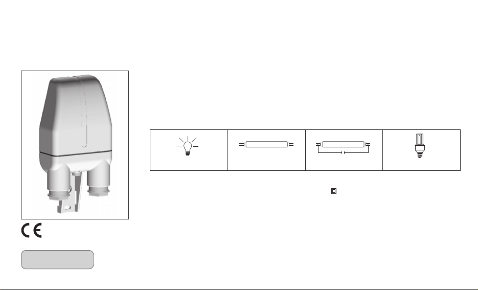
POLE-MOUNTED PHOTOCELL SWITCH WITH INTERNAL SENSOR
- Threshold adjustable from 2 to 200 LUX
- The product is supplied pre-adjusted for 10 LUX
1 – TECHNICAL DATA
Supply voltage:
Type of action, disconnect and device:
Type of output:
Example of maximum operating power:
230V~ 50 ÷ 60 Hz
1 / B / Electronic
Relay with NA single-pole polarized contact,
16(3)A / 250V~
3500 W / 230V~ cos =1j
PC - DEICNN002 /010 4
ENGLISH
2300 W (23 x 100 W)
Maximum wire section at terminals:
Insulation:
Protection degree:
Pollution:
Activation threshold:
Switch on/switch off delay:
Operating temperature limits:
Storing temperature limits:
Installation:
Reference standard for CE mark:
(directives 73/23/EEC and 89/336/EEC).
700 W (12 x 58 W)
290 W (5 x 58 W 35 µF)
2,5 mm²
Class II
I65P
Normal
2÷200 LUX adjustable
25 seconds approx.
-30 °C ÷ +60 °C
-30 °C ÷ +65 °C
For external use (e.g. pole)
LVD EN60669-2-1
EMC EN60669-2-1
105 W (7 x 15 W)
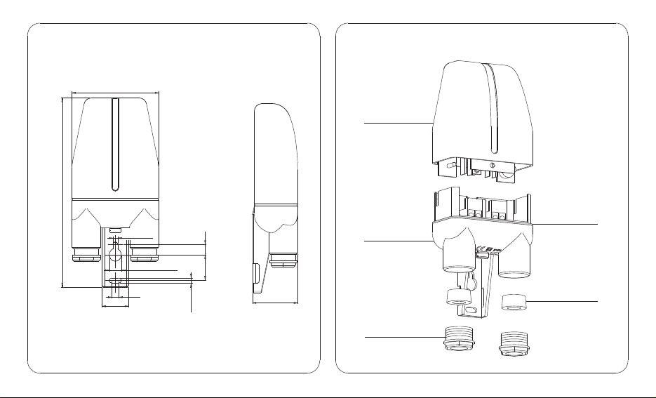
Dimensions
147
Components
72
Dome
Gasket
Æ 4.2
8
Base
Æ 10
6
22
fig.1
2
Æ 4.2
20
Cable entry fitting
37.5
Cable clamp
fig.2

2 - INSTALLATION
Important: installation and electrical connections of devices and
appliances must be carried out by skilled persons and in compliance with
current regulations.
The manufacturer declines any liability in connection with the use of
products subject to special environmental and/or installation standards.
Note for installer
Ensure in advance that all cables (especially power) are properly routed
and ducted in accordance with installation standards.
Installation of switch
device intended for external installation (e.g. pole)
remove the dome
fix the base of the device with screws or clips, utilising the holes
provided in the bracket
disconnect the mains supply
slip the cable clamp nuts over the cables (maximum external diameter
of cable 11mm)
pierce the web of the rubber grommets and slip the grommets over the
cables (fig. 3)
insert the ends of the cables into the base and make the electrical
connections
connect the 230V power supply conductors to the terminals:
L = live, N = neutral
connect the lamp as indicated in fig.4 (options "A" or "B")
locate the rubber grommets of the cable entry fittings in their seats
tighten the cable clamp nuts to ensure a hermetic seal
Cable entry
L
N
fig. 3
Electrical connections
Option “A” Option “B”
Orientation of
cable entry fitting
LN
LN
Important: in cases where a single cable is routed to the switch, the
cable entry not utilised must be sealed by
inserting the rubber grommet (unpierced) tightening the cable clamp nut.
L
230 V~
L
NN
230 V~
fig. 4
3

3 – FITTING THE DOME
check the correct positioning of the gasket on the base
position the dome (fig. 5) and press down until the captive screw is
engaged; the adjustment trimmer and the threshold trip indicator LED
should be visible (fig. 6), and the faston clips of the circuitry should
be in contact with the terminals on the base.
4 - SETTING
switch on the power supply
make the threshold adjustment (from 2 to 200 LUX) by turning the
trimmer (fig.6); the LED will light up to indicate correct operation of the
sensor.
N.B. The device is factory set to 10 Lux
Fitting the dome
fig.5
4
Setting position
10
Lux
2
200
L
N
LED
TRIMMER
10 Lux
fig.6

5 – CLOSING THE DEVICE
Secure the dome by tightening the captive screw inserted through the
bottom of the base. Tighten the screw until the dome presses on the
gasket sufficiently to ensure a hermetic seal (fig. 7).
WARNING: in the case of particularly reactive loads (e.g.
fluorescent or HID or electronic lamps, etc.) or with a cos valuej
lower than those indicated in the technical data, the relay could
suffer damage. It is advisable in such instances to use a suitably
rated external relay or solenoid switch.
WARNING: according to Italian safety standards governing
electrical systems and equipment (CEI 64-8), electrical connections
must be made only after isolating the 230V~ power line.
Closing the device
fig.7
5

6 – OPERATION
The pole-mounted photocell switch pilots the switching on and off of
external lighting systems. The contact of the switch will close when the
level of daylight falls below the set threshold and stay closed until the
daylight returns above the threshold. For correct operation, the photocell
switch must be installed in such a way that it will remain unaffected when
the lamps to which it is connected are ignited or energized (see fig.8).
7 - MAIN SPECIFICATIONS
Designed and manufactured employing the most recent technologies,
reflected in all its components, this pole-mounted photocell switch is also
intended to make the work of installers easier.
- The entire device is opened and closed by loosening and retightening a
single "captive" screw.
- The light-sensitivity adjustment can be made with the device under load
and in complete safety, simply by selecting the setting position (fig. 6).
- The dome containing the circuitry is replaceable as a separate
component, keeping the base and cables in position and permanently
wired, making for considerably shorter job times when servicing is
required.
With advantages such as these and the superior technical specifications
of the product, purchasers have the ideal solution for controlling outdoor
lighting installations.
The manufacturer reserves the right to make all technical and manufacturing modifications deemed necessary
without prior notice.
6
Example of installation
YES
NO
fig. 8
 Loading...