

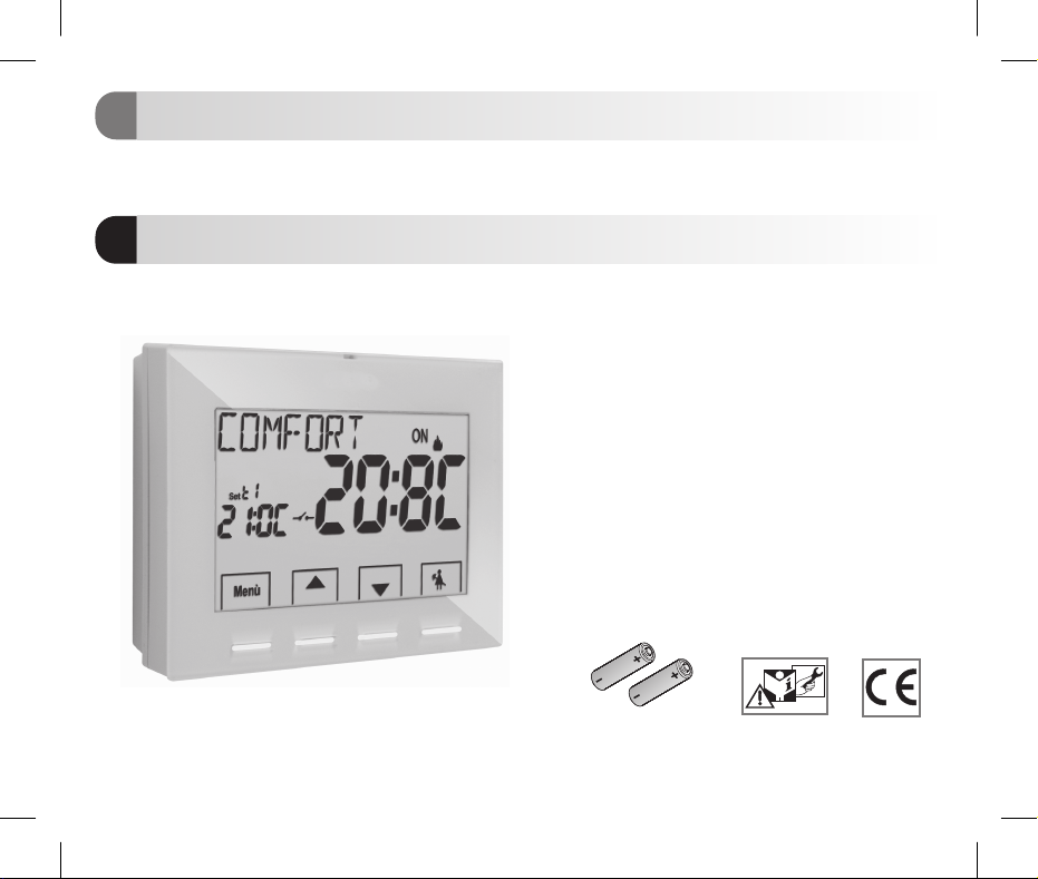
TERMOSTATO DIGITALE
IT
NAVIGAZIONE A MENU e DISPLAY LUMINOSO
Installazione da parete
DIGITAL THERMOSTAT
EN
MENU DRIVEN with BACKLIT DISPLAY
Wall mounting
PE - DETEPE001 06/16
Alimentazione a pile
Inverno / Estate
2 livelli di temperatura + antigelo
Ingresso per contatto remoto
Ingresso per sonda di temperatura remotabile
Battery-operated
Winter / Summer
2 temperature levels + antifreeze
Input for remote contact
Input for remote temperature probe
2x 1,5V dc LR6-AA
(not included)

IT
INDICE
ITALIANO
PRESENTAZIONE
AVVERTENZE
1 - DATI TECNICI
2 - IMPOSTAZIONI DI FABBRICA
3 - LEGENDA TASTI
4 - LEGENDA DISPLAY
5 - INSTALLAZIONE
5.1 - Dimensioni di ingombro
5.2 -
Esempi di installazione
5.3 - Fissaggio della base a parete
5.4 - Collegamenti elettrici
5.5 - Fissaggio o rimozione del termostato dalla base a parete
5.6 - Segnalazione pile quasi scariche o scariche
5.6.1 - Inserimento o sostituzione pile
6 - ACCENSIONE DEL TERMOSTATO
7 - USO DEL TERMOSTATO
7.1 - Cambio da temperatura
di COMFORT a ECONOMY (risparmio) e viceversa
7.2 - Modifica temperatura T Set impostata
7.3 - Sospensione della termoregolazione
7.4 - OFF (esclusione del termostato)
8 - STRUTTURA DEI MENU PRINCIPALI (uso e configurazione)
9 - ACCESSO AI MENU
10 - MENU PER L’UTENTE
10.1 - Impostazione modalità INVERNO o ESTATE
10.2 - Modifica o esclusione del set di temperatura antigelo
10.3 - Menu PASSWORD UT (utente)
10.3.1 - Inserimento della password utente
10.3.2 - Modifica o annullamento della password
2
pag. 3
11 - MENU PER LA CONFIGURAZIONE (installatore)
11.1 - Accesso al menù configurazione
pag. 3
11.2 - Modifica della lingua impostata
pag. 4
11.3 - Tipo di modalità di regolazione della temperatura
pag. 5
11.3.1 - Selezione della modalità di regolazione della temperatura
pag. 6
pag. 7
pag. 8
pag. 8
pag. 8
pag. 8
pag. 9
pag. 10
pag. 11
pag. 11
pag. 12
pag. 13
pag. 13
pag. 13
pag. 13
pag. 14
pag. 14
pag. 15
pag. 16
pag. 16
pag. 16
pag. 17
pag. 17
pag. 17
(differenziale on/off o proporzionale)
11.3.2 - Impostazione dell’isteresi per il differenziale termico ON-OFF
11.3.3 - Impostazione durata del periodo per il Proporzionale modulante
11.4 - Modifica dell’unità di misura per la lettura della temperatura
11.5 - Correzione lettura della temperatura ambiente
11.6 - Blocco set temperatura max e min (modalità inverno ed estate)
11.7 - Menu sonda
11.7.1 - Nessun collegamento a sonda separata
11.7.2 - Impostazione sonda separata remota
11.7.3 - Impostazione sonda pavimento
11.7.4 - Impostazione sonda separata esterna
11.8 - Collegamento a contatto esterno per accensione/spegnimento
da remoto del termostato
11.8.1 - Attivazione / disattivazione con Programmatore telefonico
11.8.2 - Obbligo NA - per contatto normalmente aperto
11.8.3 - Obbligo NC - per contatto normalmente chiuso
11.9 - Ciclo anticalcare
11.10 - Regolazione contrasto del display
11.11 - Retroilluminazione
11.12 - Inserimento e gestione delle password
11.12.1 - Inserimento nuova password
11.12.2 - Modifica o annullamento della password
11.13 - Restore (Reset)
11.14 - Informazioni software di sistema
12 - EVENTUALI INCONVENIENTI E SOLUZIONI
pag. 18
pag. 18
pag. 18
pag. 19
pag. 19
pag. 20
pag. 20
pag. 20
pag. 21
pag. 21
pag. 23
pag. 23
pag. 24
pag. 24
pag. 25
pag. 25
pag. 26
pag. 27
pag. 27
pag. 28
pag. 28
pag. 28
pag. 29
pag. 29
pag. 29
pag. 30
pag. 30
pag. 31
PRESENTAZIONE
Gentile Cliente, La ringraziamo per aver scelto un nostro prodotto.
II termostato è adatto a tutti gli impianti di riscaldamento e/o raffrescamento, è dotato di un chiaro display retroilluminato per tenere sotto
controllo tuttele sue funzioniin tempo reale.La facilità diutilizzo tramite navigazionea menù èla caratteristica fondamentale,infatti, nonostante
la completezza delle sue funzioni, è facilissimo da usare. Il termostato, di fabbrica, regola la temperatura in modo Differenziale ON/OFF e
l’isteresi è impostabile da 0,2°C a 1,2°Cper adattarsi all’inerzia termica del Vostro specifico impianto;in alternativa è possibile selezionare il
funzionamento in modoProporzionale modulante con cicli didurata impostabili(da 7 a 20 minuti):questo sistemapermette di mantenerepiù
stabile latemperaturadesiderata, aumentandolasensazione dicomfort perl’utente edèparticolarmenteadatto pergliimpianti conaltainerzia
termica come, adesempio, peri pannelliradianti sottopavimento.La scaladi temperaturaimpostata difabbrica èin gradiCentigradi (Celsius)
con la possibilità dicalibrare la misurazione dellatemperatura ambiente impostando un valore di correzione (da-3 a +3 °C). Al termostato è
possibile collegare una sonda ditemperatura separata remotabile (in opzione)e successivamente impostarla secondo leproprie esigenze di
impianto: remota,apavimento, esterna.Particolare attenzioneè statariservata alrisparmio energetico:la sospensione dellatermoregolazione
per pulizie domestiche, il blocco opzionale delle temperature di Set impostate (MAX/MIN), il valore della temperatura antigelo regolabile, il
comando tramite un contatto esterno (esempio programmatore telefonico in opzione), consentono di evitare sprechi di energia con
conseguente risparmio economico:vedere ladescrizione di questeed altrefunzioninellepagine successive.
AVVERTENZE!
Leggere attentamente il presente manuale prima di utilizzare il prodotto, in quanto fornisce impor tanti indicazioni riguardanti la
sicurezza, l’installazione el’uso. Conservare con curail manualepersuccessiveconsultazioni.
L’installazioneed ilcollegamentoelettrico del termostatodevono essereeseguitidapersonale qualificato edin
conformità alle normee leggivigenti.
Il termostato non andrà utilizzato da persone (compresi bambini) con capacità fisiche, sensoriali e mentali ridotte, o mancanza di
esperienza e conoscenza delle istruzioni, a meno che vengano supervisionati o abbiano ricevuto le dovute istruzioni che riguardano
l’uso dell’apparecchio daparte di unapersona responsabileperlalorosicurezza.
I bambini andrannosupervisionatiperassicurarsiche non giochinocon l’apparecchio.
Se apparesul display ilvalore dellatemperatura ambiente (+23°F o+ 99,9 °F)in modolampeggiante, significache-5 °Co +37.7 °C
la .temperatura rilevata èoltre ilimitidiscala
Se il displayvisualizza “ ” lampeggiante indicasonda guasta:ogniattivitàdi termoregolazione vienesospesa.Err
Utilizzare 2 pilestilo da 1,5V tipoAA (LR6);pilenonincluse nella confezione.alcaline
N.B.: il prodottoè statotestato e garantisce le sue caratteristichecon pile alcaline DURACELL o ENERGIZER.
In caso dinecessità pulirecondelicatezzail termostato eil displayutilizzandoun panno morbidoe asciutto.
Il costruttore siriserva la facoltà diintrodurretuttelemodifichetecniche e costruttivecheriterrà necessarie senzaobbligo dipreavviso.
IT
3
IT
1 - DATI TECNICI
1 - DATI TECNICI
Alimentazione:
Autonomia:
Autonomia dall'accensione sul display
del simbolo lampeggiante di “pile scariche”:
Retroilluminazione di colore bianca del display:
Tipo di azione, disconnessione ed apparecchio:
Tipo di uscita:
Software:
Tensione impulsiva nominale:
Sezione dei fili ai morsetti:
Ingresso contatto per accensione/spegnimento da remoto:
Ingresso per sonda separata remota:
Tipo di isolamento:
Grado di protezione:
Grado inquinamento:
Numero livelli di Temperatura:
Scala di visualizzazione temperatura ambiente:
Campo di visualizzazione soglia sonda pavimento:
Campo di visualizzazione sonda esterna:
Segnalazione relè ON:
Risoluzione indicatore temperatura ambiente:
Campo di reg. set di temperatura:
Impostazione Set di temperatura:
Correzione temperatura (Offset):
Temperatura antigelo (t ):
Modalità di regolazione della temperatura:
- DIFFERENZIALE ON/OFF (default)
- PROPORZIONALE MODULANTE
Gradiente termico:
Tolleranza sulla lettura di temperatura:
Limiti della temperatura di funzionamento:
Limiti della temperatura di stoccaggio:
ErP classificazione energetica:
4
Normative di riferimento per marcatura CE:
n° 2 pile stilo 1,5 V tipo AA (LR6)alcaline
circa 2 anni
circa 15 giorni
temporizzata 6 sec. (default) / sempre spenta
1 / B / U / Elettronico
a relè con contatto in scambio COM / NA / NC,
libero da potenziale - max 5(3)A/250 V ~
classe A
4 kV
22
1,5 mm ÷ 2,5 mm
per contatto remoto NA o NC libero da potenziale
si - sonda impostabile a seconda dell’utilizzo: remota, pavimento, esterna
classe II
I30P
normale
n° 2 « = COMFORT», « = ECONOMY» + t antigelot1 t2
- 5.0 °C ÷ + 37.7 °C (+ 23 °F ÷ +99.9 °F)
- 0.0 °C ÷ + 60.0 °C (+ 32 °F ÷ +140 °F)
- 9.9 °C ÷ + 60.0 °C ( +14.2 °F ÷ +140 °F)
+ ON (inverno) o + ON (estate) lampeggianti
0.1 °C (0.1 °F)
+5 °C ÷ +37.7 °C (+41.0°F ÷ +99.9 °F) limitabile
a step di 0.1 °C / 0.1 °F
regolabile da -3.0 °C (5.4°F) a +3.0 °C (5.4°F) default 0.0 °C/0,0 °F
regolabile + 5 °C ÷ <t2 (41,0 °F ÷ <t2) default 6 °C (42.8 °F)
regolabile da 0.2 °C a 1.2 °C (da 0,3 °F a 2.1 °F) default 0,3 °C (0,4°F)
cicli di durata impostabili da 7a 20 minuti (default 10 minuti)
max 1°K / 15 min
± 0,5°C (± 0,9°F)
0 °C ÷ +45 °C
-10 °C ÷ +60 °C
ErP Class I; 1% (Reg. EU 811/2013)
LVD - EMC EN60730-2-7 EN60730-2-9
2 - IMPOSTAZIONI DI FABBRICA
I dati inseritineltermostato denominati «IMPOSTAZIONIDIFABBRICA»si riferiscono adun funzionamentodefinito «Standard».
Nei capitoli seguenti verranno descritte tutte le funzioni personalizzabili, al fine di soddisfare ogni esigenza di comfort
ambientale.
TABELLA IMPOSTAZIONI DI FABBRICA (default)
Parametro
Lingua
Stagione attiva
Unità di misura temperatura
Set t1 COMFORT Inverno
Set t2 ECONOMY Inverno
Set t antigelo (Inverno)T
Set t1 COMFORT Estate
Set t2 ECONOMY Estate
Blocchi temp. Inverno
Blocchi temp. Estate
Modo di regolazione temp.
Isteresi differenziale
Proporzionale modulante
Periodo modulante
Correzione temp. ambiente
Correzione temp. ambiente
Ciclo di protezione anticalcare
Contrasto display
Retroilluminazione display
Sonda remota
Ingresso esterno
Password utente
Password installatore
Codice di ripristino password
Default
IT (Italiano)
Inverno
°C (celsius)
20.0°C
18.0°C
6.0°C
24.0°C
27.0°C
Disattivato
Disattivato
DIFF. ON/OFF
0.3°C
Prop (non attivo)
10 min. (non attivo)
0,0 °C
0,0 °C
Disattivato
Livello 6
Temporizzata 6 sec.
(non attiva)
(non attivo)
nessuna
nessuna
0927
Restore «reset»
Da confermare
Default
Ultimo valore
Default
Default
Default
Default
Default
Default
Default
Default
Default
Default
Default
Default
Default
Ultimo valore
Default
Default
Ultimo valore
Ultimo valore
Default
Default
Default
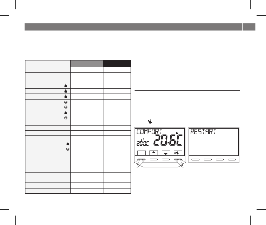
RESTORE «RESET installatore»
Ripristino di molte impostazionidi fabbrica(default)
Il RESTORE riporta il termostato alle impostazioni di fabbrica ad
eccezione di alcune voci come riportato in tabella; per eseguire
l’operazione seguire le indicazionial paragrafo11.13.
RESTART
Non annulla le impostazioni inserite
Nel caso in cui il termostato presentasse mal funzionamenti,
visualizzazioni errate o altre situazioni non corrette, effettuare un
« ». Premere contemporaneamente per 4 sec. i tastiReset utente
Menu .e ll termostato riprendeil normalefunzionamento.
Set
SetT
Menù
back
Premere contemporaneamente per 4 sec.
Set
0
6810
2 4
SetT
Menù
back
12 14
161820
22
OK
IT
5
IT
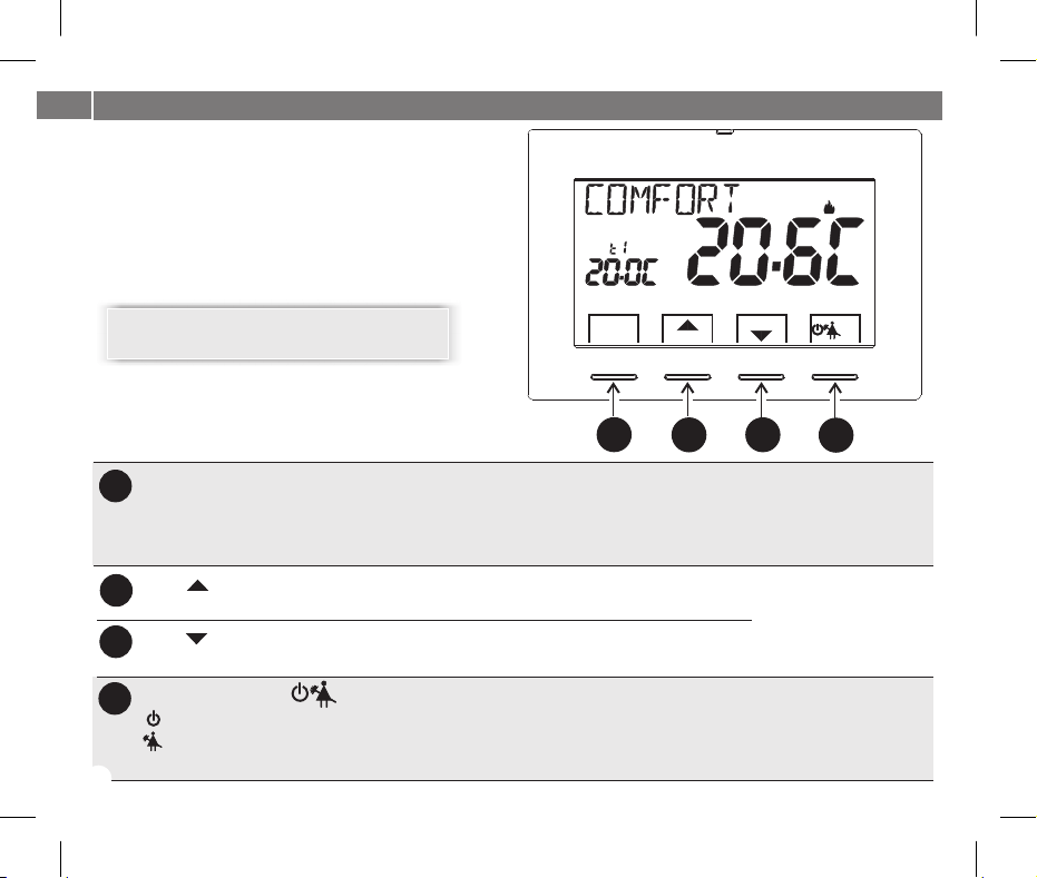
3 - LEGENDA TASTI
Display retroilluminato
Alla pressione di un qualsiasi tasto la retroilluminazione
si attiva visualizzando le scritte di scelta e navigazione,
entro 6 sec. premere il tasto desiderato per variare le
impostazioni (ad ogni tocco su un tasto viene riattivato
un time-out di6 sec).
Set
Nota: ulteriori particolari funzioni dei tasti sono
descritte negli specificiparagrafi di utilizzo.
Menù
back
SetT
A
Tasto multifunzione Menu/back,
A
a seconda della funzione o menu attivo varia il suo utilizzo:
Menu = pressione breve passaggio da temperatura di comfort ad economy e viceversa,
pressione prolungata (3 sec.) accesso ai menu
back = ritorno alla voce precedente, uscita dai menu
Tasto aumenta Set di temperatura desiderata;
B
Tasto diminuisce Set di temperatura desiderata;
C
Tasto multifunzione
D
OK
6
navigazione fra i menu: permette di aumentare il valore di una impostazione
navigazione fra i menu: permette di diminuire il valore di una impostazione
OK
termostato in OFF (termoregolazione disattivata)
sospensione della termoregolazione per pulizie domestiche
accesso al menu scelto / conferma funzione o valore impostato (all’interno dei menu)
OK
B
C
D
Premere iltasto a frecciaad impulsi
per incremento/decremento
singolo, mantenere premuto per
incremento/decrementoveloce.
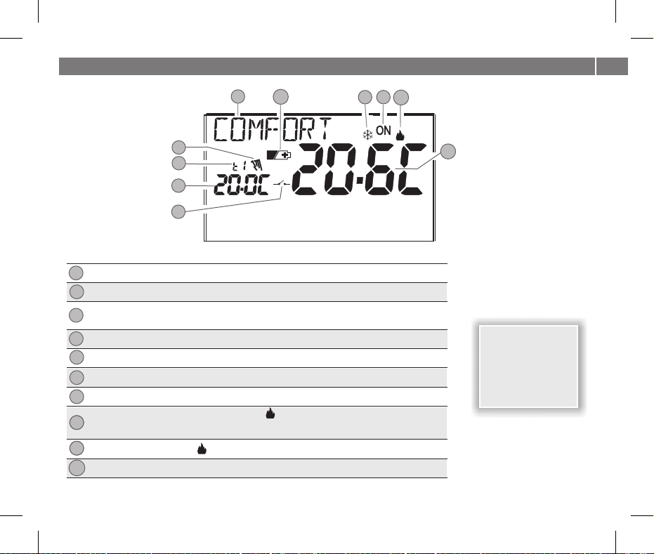
4 - LEGENDA DISPLAY
IT
5
6
7
4
3
Set
2
1
Attivazione del termostato da comando remoto
1
Visualizzazione temperatura di Set impostata
2
Set di temperatura al momento attivo a seconda dell’impostazione desiderata
3
Comfort o Economy (risparmio) o antigelot1 t2 t
Sospensione della termoregolazione (esempio: per pulizie domestiche)
4
Info e modo di funzionamento del termostato, voci del menu
5
Segnalazione pile scariche
6
Modalità raffrescamento ( Estate) attiva
7
Segnalazione utenza in funzione = e lampeggiantiON
8
8
Modalità riscaldamento ( Inverno) attiva
9
8
Temperatura ambiente rilevata
10
T
SetT
Menù
back
T
ONSegnalazione utenza in funzione = e lampeggianti
T
(es. caldaia accesa)
(es. condizionatore acceso)
8
9
10
OK
Nota: ulteriori
visualizzazione del
display sono
descritte negli
specifici paragrafi di
utilizzo.
7
IT
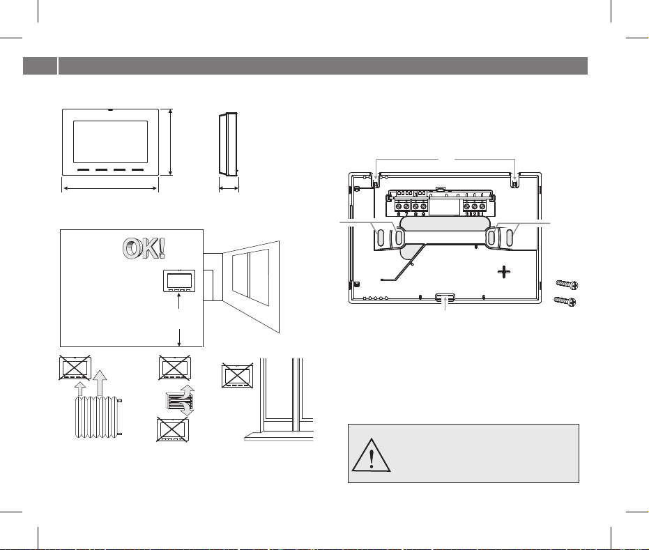
5 - INSTALLAZIONE
5.1 - DIMENSIONI DI INGOMBRO
88
128
26
5.2 - ESEMPI DI INSTALLAZIONE
h 1,5 m
Installare preferibilmente il termostato a quota 1,50 ÷ 1,60 m dal
pavimento; lontano da sorgenti di calore, prese d'aria, porte o finestre e
da quanto possa influenzarneil funzionamento.
8
5.3 - FISSAGGIO DELLA BASE A PARETE
! Disattivare la tensionedi rete230V~
! Fissare conle vitiin dotazione labase deltermostato: aparete, alla
scatola da incasso tonda o rettangolare utilizzando le opportune
coppie di fori .A
C
A
B
D
A - fori difissaggio dellabase:amuro,scatolaincassotonda
o rettangolare
B - passaggiofili datubocorrugato, scatolaincasso tonda
o rettangolare
C - ganci peraggancio deltermostato
D - cava difissaggio deltermostato
E - viti perfissaggio dellabaseapareteallascatolaincasso
tonda o rettangolare
Per assicurare un corretto montaggio del
termostato alla base aparete, lastessa nondeve
presentare incurvature dovute all’eccessivo
serraggio delle viti di fissaggio nella scatola
rettangolare o tonda incassataa muro.
A
E
5 - INSTALLAZIONE
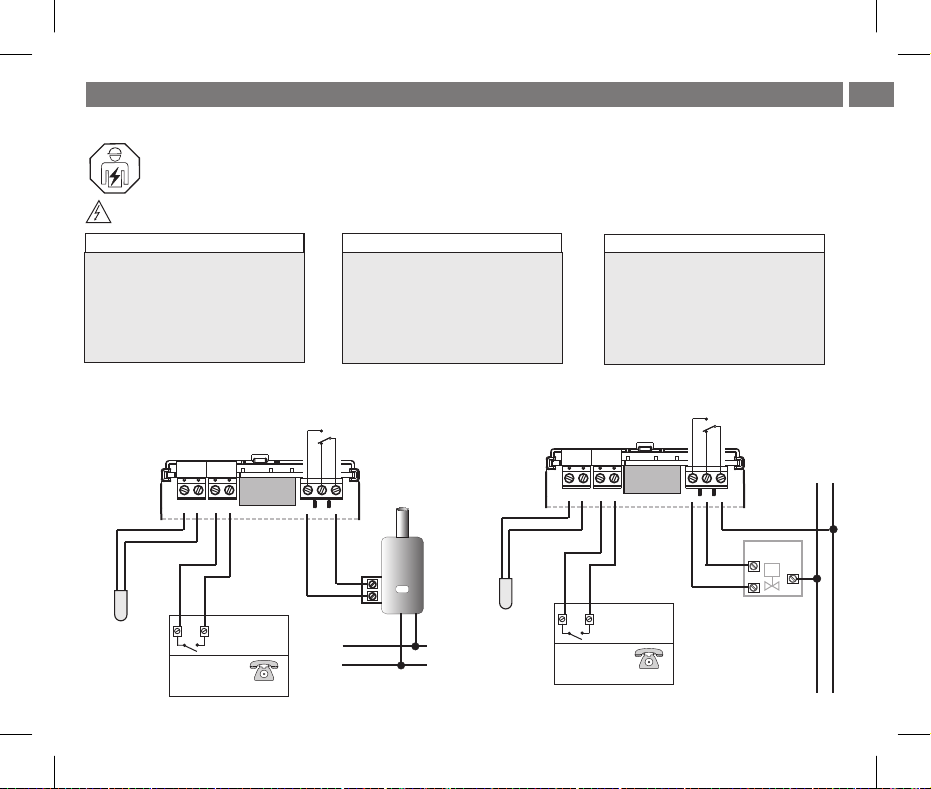
5.4 - COLLEGAMENTI ELETTRICI
Importante: l’installazioneed ilcollegamento elettricodei dispositivi edapparecchiature devonoessere eseguitida personale
qualificato edin conformitàalle norme e leggi vigenti. Il costruttore non siassume alcunaresponsabilità perquanto concerne
l’impiego di prodottiche debbano seguirepar ticolarinorme diambientee/o installazione.
Disattivare la tensione di rete 230V~ che alimenta i dispositivi da comandare
Morsetti relè
! collegare il dispositivo da comandare
ai morsetti:
1 - comune (C)
- contatto normalmente chiuso (NC)2
- contatto normalmente aperto (NA)3
Esempi di collegamenti elettrici
Collegamento ad una caldaia
AUX 1
AUX 2
Morsetti AUX 1 (sonda remota)
! 67aimorsetti e è possibilecollegare
una sonda di temperaturaseparata
(vedere paragrafo 11.7 per
l’impostazione della sonda)
nota: lunghezza max dei cavi 4 m
NA
C
NC
1239876
Morsetti AUX 2 (contatto remoto)
! 89ai morsetti e è possibilecollegare
un programmatore telefonico (o
interruttore) per l’attivazione del
termostato adistanza
(vedere paragrafo 11.8 per
impostazione contatto esterno)
Collegamento ad una valvola motorizzata
AUX 1
AUX 2
IT
NA
C
NC
230V~
N
L
1239876
separata (opzionale)
Sonda di temperatura
Contatto per il comando
del termostato a
distanza
esempio:
Programmatore
telefonico
(opzionale)
CALDAIA
separata (opzionale)
Sonda di temperatura
L
230V~
N
Contatto per il comando
del termostato a
distanza
esempio:
Programmatore
telefonico
(opzionale)
chiude
apre
CARICO
M
230V~
9
IT
5 - INSTALLAZIONE
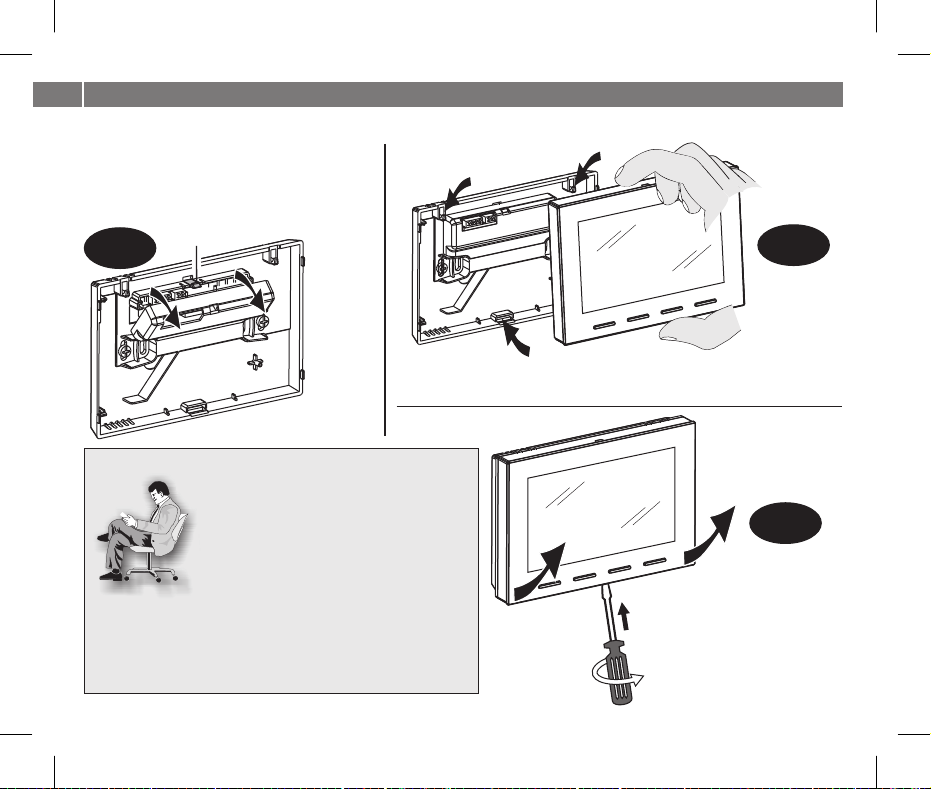
5.5 - FISSAGGIO O RIMOZIONE DEL TERMOSTATO DALLA BASE A PARETE
Dopo aver eseguito icollegamenti elettrici:
! Applicare il coperchietto coprimorsetti alla base
fissandolo nel gancio .E
! Per rimuovere il coperchietto utilizzare un piccolo
cacciavite facendo leva sul gancioE.
C
C
E
1°
D
Agganciare il termostato sulla base a parete nei ganci .C
Quindi premere il termostato in basso fino a completare il fissaggio nella cava .D
Comodità di programmazione
Tutte le operazioni di impostazione possono essere
effettuate prima di fissare il termostato alla base a parete;
ciò consente di effettuare le impostazioni stando
comodamente seduti.
L’indicazione lampeggiante con simbolo inverno oON
estate fisso e la scritta indica che il termostatoNO RELÈ
è staccato o non benfissato alla basea parete.
Qualora le impostazioni del termostato avvenissero prima del fissaggio alla base
parete, ad installazione ultimata l’indicazione (spenta o lampeggiante)ON
presente sul display potrebbe non corrispondere allo stato reale del relè.
Entro dal fissaggio del termostato alla base parete, il relè si attiveràmax1minuto
secondo l’indicazione (spenta o lampeggiante) presente sul display.ON
10
D
Sganciare il termostato dalla
base a parete premendo con un
cacciavite nell’apposita cava D
presente nella par te inferiore del
dispositivo, q ruotare peruindi
estrarlo.
2°
Rimozione del
termostato
dalla base a parete
3°
5 - INSTALLAZIONE
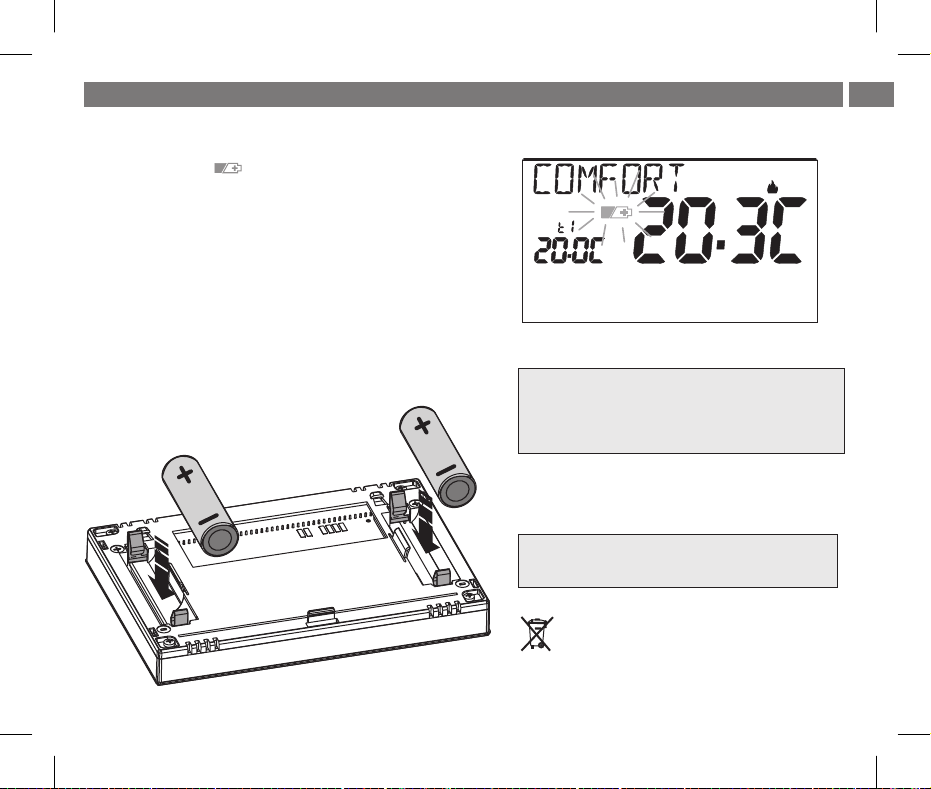
5.6 - SEGNALAZIONE PILE QUASI SCARICHE O SCARICHE
La comparsadel simbolo lampeggiante indicache lepilesistannoesaurendo;
daquestomomentosihannocirca15 giorni ditempo pereffettuare lasostituzione.
Nota: la retroilluminazione del display viene automaticamente disattivata.
Se non si sostituiscono le pile quasi scariche nei tempi dichiarati, si spegnerà
completamenteildisplay.
Ogni attività di termoregolazione viene sospesa e tutte le impostazioni vengono
memorizzateperessereripristinateall’inserimentodellenuove pile.
5.6.1 - INSERIMENTO O SOSTITUZIONE PILE
Sganciare il termostato dallabase aparete(vedereparagrafoprecedente)
Inserire le pile rispettandole polarità.
Agganciare e fissare iltermostato allabaseaparete
(vedere paragrafo precedente)
Set
Attenzione: ladurata dellepile puòrisultare superiorea
2 anni. Siconsiglia comunquedi sostituirle almenoogni
24 mesi per evitare che si esauriscano in periodi di
assenza (es. vacanzenatalizie ecc.)
UTILIZZARE PILE ALCALINEDI BUONAQUALITÀ
(consigliate pile Duracello Energizer)
alimentazione 3V dc
2 pile x 1,5Vdc LR6 - AA (non incluse)
Smaltire le pile esauste gettandole negli appositi
contenitori e comunque secondo quanto prescritto
dalle norme sullatutela dell’ambiente
IT
11
IT
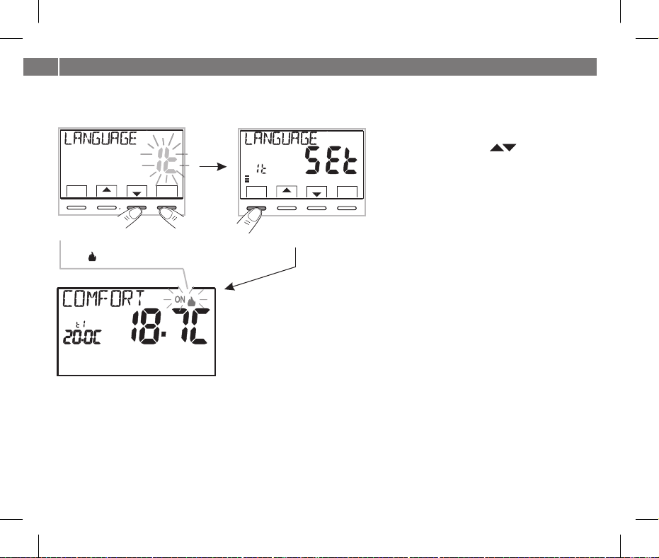
6 - ACCENSIONE DEL TERMOSTATO
Al primo inserimento delle pile, il termostato esegue un lamp-test accendendo tutti i segmenti del display visualizzando per qualche
secondo la versionedel software installato.Terminata questa fase,il termostatorichiede lascelta dellalinguada utilizzare.
Scegliere la lingua desiderata scorrendo tra le lingue
Set
0
back
Menù
6810
2 4
SetT
12 14
161820
22
OK
Set
0
Menù
back
24
SetT
4
6810
12 14
161820
disponibili utilizzando itasti .
Confermare premendoil tasto
Le lingue selezionabili sono: (default)ITALIANO =,
22
INGLESE FRANCESE TEDESCO=, =En Fr dE=, ,
OK
SPAGNOLO
ES.=
OK.
It
Premere2volte il tastoback.
1°
modalità Inverno (riscaldamento)
ON + lampeggianti = es. caldaia in funzione
2°
Premere 2 volte
il tasto back
Set
Il termostato èoperativo,visualizzasul display: lamodalità «riscaldamento»,Inverno
ilSet di temperatura a 20°CCOMFORT,latemperatura ambiente rilevata.
Dal normale funzionamento del termostato in stand-by, premendo un tasto, il display si illumina (se non è stata esclusa la
retroilluminazione) e appaiono le scritte di scelta e navigazione, entro 6 secondi, alla seconda pressione del tasto desiderato si
ottiene una variazione.
Vedereusodel termostato alcapitolosuccessivo.
12
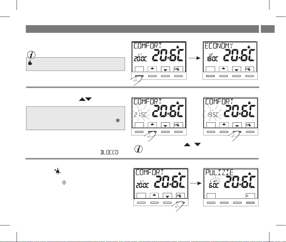
7 - USO DEL TERMOSTATO
7.1 - CAMBIO da temperatura di COMFORT a ECONOMY (risparmio) e viceversa
Premere brevemente il tasto MENU
IT
Set
INVERNO riscaldamento (impostazione di fabbrica)=
Con temperatura di COMFORT
Menù
SetT
7.2 - MODIFICA TEMPERATURA T IMPOSTATASet
Premere direttamente i tasti
Il termostato consentevalori di SET ditemperatura che soddisfino
le seguenti condizioni:
Inverno:t1 t2 tmaggiore o uguale a maggiore o uguale
Estate: t2 t1maggiore o uguale a
In presenza di blocchi per la temperatura max e min. (vedere
paragrafo 11.6) non si potrà impostare un superiore oSet t
inferiore ai blocchi inseriti. Il display segnalerà l’impossibilità
ad eseguire il comandovisualizzando lascritta .
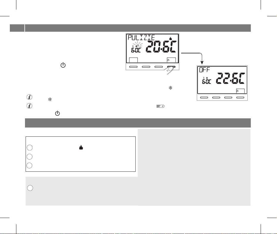
7.3 - SOSPENSIONE DELLA TERMOREGOLAZIONE
Premendo iltasto siavrà lospegnimento dell'utenzaallacciata
per unperiodomax di 3oredurante le qualiiltermostato simetterà
in modalità antigelo ( ).t
Trascorsele 3ore,iltermostato riprenderà latermoregolazione.
Sarà possibile riattivare la termoregolazione prima del termine
delle 3 ore, premendo« »: lascritta «PULIZIE»scompare.back
Nota: nel caso siastata esclusainmodopermanentelatemperaturaantigelo
o in funzionamento “Estate”,l’utenza allacciata(es.caldaiaocondizionatore)resteràdisattivatapermax3ore.
Set
SetT
Ogni pressione dei tasti o comporta la variazione di 0,1 gradi;
tenendo premuto si ottiene lo scorrimento veloce dei valori.
Range: +5 °C a +37,7°C (+41,0°F ÷ 99,9°F).
(esempio per pulizie domestiche)
Set
SetT
Menù
Set
SetT
Menù
Set
SetT
Set
SetT
back
13
IT
7 - USO DEL TERMOSTATO
7.4 - OFF (esclusione del termostato)
Questa impostazione ha il compito di bloccare le funzioni
del termostato quando il riscaldamento o il raffrescamento
devono rimanere spenti.
1- Nellacondizione di«PULIZIE» (paragrafo 7.3),premendo
brevemente il tasto si pone il termostato in con ilOFF
conseguente «Spegnimento dell’impianto»
2- OFFSul displaycompare lascritta , ad indicare cheil termostatoè disattivatoe tutte le funzioni sono
inattive; rimangono in funzione la lettura della temperatura ambiente, la modalità anticalcare se
attivata e se inmodalità INVERNOilSetditemperaturapiùilsimbolodiprotezioneantigelo .t
in modalità INVERNO condisattivata la temperaturaantigelo oppure inmodalità Estate, non saràvisibile il
simbolo t .
in caso di pile scariche, si attiverà sul display la visualizzazione lampeggiante del simbolo .
3- per riattivare il termostatoPremereiltasto .
Set
SetT
back
8 - STRUTTURA DEI MENU PRINCIPALI (uso e configurazione)
I Menu sono disposti in modo sequenziale
Menu utente:
1 STAGIONE (modalità Inverno o Estate)
2 SET TEMP
(modifica o esclusione del Set temp. antigelo)
T
3 PASSWORD UT(impostazione password utente)
Menu installatore o utente esperto:
4 CONFIG
- LANGUAGE (selezione della lingua desiderata)
- REGOLA (selezione della modalità di regolazione della temperatura)
14
- UNITÀ (selezione dell’unità di misura della temperatura °C/°F)
- OFFSET (correzione della temperatura ambiente rilevata)
- BLOCCHI (consente di limitare il valore dei Set di temperatura)
- SONDA )(impostazione di una sonda di temperatura remota
- INGRESSO (impostazione di un contatto esterno per attivazione/
- POMPA ON (disattivazione / attivazione della funzione anticalcare)
disattivazione del termostato a distanza)
- RISALTO (consente di modificare il valore di contrasto del display)
- RETROLED
- PASSWORD
- RESTORE (operazione di RESET)
(consente di attivare/disattivare la retroilluminazione del display)
(consente di inibire l’utilizzo di funzioni utente e/o
installatore del termostato)
- INFO SW (informazioni in merito alla versione del firmware installato)
Set
18
20
22
OK

9 - ACCESSO AI MENU
Dalla condizione di normalefunzionamento deltermostatotenendopremuto il tasto per 3 sec. siaccede alprimomenudisponibile.Menu
Oppure, un codice diaccesso segretoutente e/o installatore, seguire ipassaggi sottoriportati perse è statoprecedentemente inserito
accedere ai menu utenteo installatore.
schermata principale
in presenza della password utente e installatore
IT
per
3 sec.
Set
SetT
Menù
in presenza di sola
password utente
Set
0
6810
2 4
SetT
Menù
back
12 14
161820
22
OK
1°
esempio inserimento di una password
nessuna password inserita
Set
0
2 4
SetT
Menù
back
Set
0
back
2 4
SetT
Menù
6810
1°
6810
12 14
12 14
161820
161820
2°
22
OK
22
OK
Set
0
6810
2 4
SetT
Menù
back
1°
dopo l’inserimento password utente
si accede al 1° menu utente
(vedere paragrafo successivo)
12 14
161820
2°
22
OK
Set
0
6810
2 4
SetT
Menù
back
L’utilizzo dei tasti OKconsente di scorrere tra i menù: premendo si entra nel menu scelto,
premendo si ritorna alla voce precedente. All’interno dei menu le impostazioni devono essere
back
confermate premendoil tasto in casocontrario, trascorsi3minuti,il termostatotornaalOK ove richiesto,
normale funzionamentoin stand-byelemodifichenonsarannoconservate.
Set
0
6810
2 4
SetT
Menù
back
12 14
161820
22
OK
2°
La scritta per
alcuni secondi dopo la
pressione del tasto OK
12 14
161820
Set
0
2 4
SetT
Menù
back
indica password non
22
corretta.
OK
dopo l’inserimento password
installatore si accede alla
1° voce del menu CONFIG
(vedere par. 11.1)
6810
12 14
161820
22
OK
15
IT
10 - MENU PER L’UTENTE
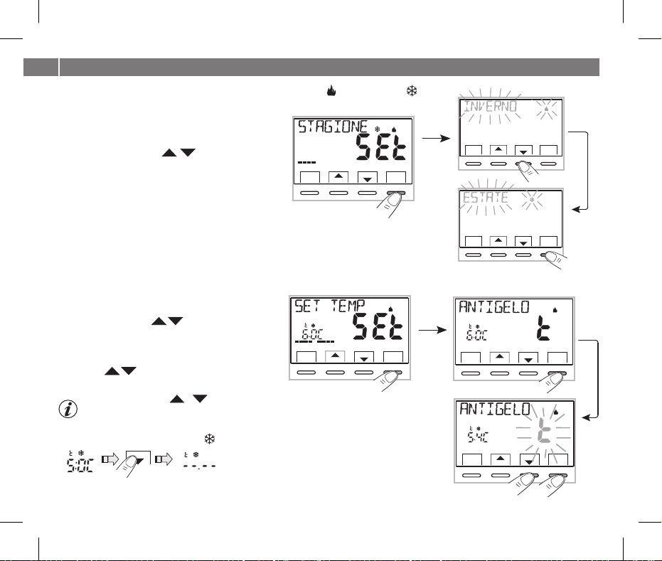
10.1 - IMPOSTAZIONE MODALITÀ INVERNO O ESTATE
Dal normale funzionamento del termostato, accedere ai menu
tenendo premuto il tasto« ».Menu
Alla voce STAGIONESEt OKconfermare con .
Selezionare con i tasti la modalità INVERNO
(riscaldamento) o ESTATE (raffrescamento).
Confermare conil tasto .OK
Premereiltasto« » peruscire.back
Set
0
Menù
back
6810
2 4
SetT
12 14
161820
default:
0
6810
2 4
12 14
SetT
Menù
back
22
OK
Set
0
6810
2 4
12 14
SetT
Menù
back
10.2 - MODIFICA O ESCLUSIONE DEL SET DI TEMPERATURA ANTIGELO
Dal normale funzionamento del termostato, accedere ai
menu tenendo premuto tasto« ».Menu
Selezionare con i tasti .voce SET TEMP SEt
Confermare conOK.
il display visualizza lascritta ANTIGELO
Confermare conil tasto .OK
Con i tasti impostare la temperatura antigelo
desiderata.
Ogni pressione dei tasti o comporta la variazione di 0,1 gradi;
tenendo premuto si ottiene lo scorrimento veloce dei valori.
Range: +5 °C a +12°C
Per disattivarela temperaturaantigelo t , scenderesotto i +5.0 °C .(41.0 °F)
Set
Set
temperatura antigelo disattivata
Confermare con OK. Premere il tasto « » per uscire.back
16
Set
0
6810
2 4
SetT
Menù
back
12 14
161820
22
OK
Set
0
6810
6810
12 14
12 14
2 4
SetT
Menù
back
Set
0
2 4
SetT
Menù
back
1°
161820
161820
161820
161820
2°
22
OK
22
OK
22
OK
22
OK
10 - MENU PER L’UTENTE
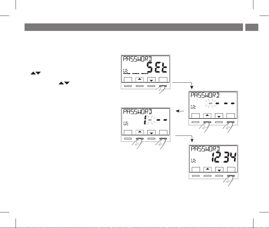
10.3 - MENU PASSWORD UT (UTENTE)
10.3.1 - Inserimento della password utente
Nella configurazione di fabbrica non viene impostato nessun codice.
Dal normale funzionamentodel termostato,accedere
ai menu tenendo premutotasto« ».Menu
1- Selezionare la voce PASSWORD Ut SEt con i tasti
2- Utilizzando i tasti , inserire 4 cifre (esclusi i
trattini) comprese tra e , confermandole0000 9999
singolarmente premendoil tasto« ».OK
il termostato sidispone innormalefunzionamento
Da questo momento, per qualsiasi variazione sul
termostato, verrà richiesto l’inserimento della
password.
10.3.2 - Modifica o annullamento della password
Premere il tasto e digitare la password precedentementeMENU per 3 sec.,
impostata; seguendo la procedura sopra descritta accedere al menu
PASSWORDUtSEt:
- impostando 4 trattini(- ---),lapasswordverràannullata,
- impostando un altronumeroverràmodificata.
OKe confermareconiltasto .
0246810
SetT
Menù
back
Set
0246810
SetT
Menù
back
1°
12 14
12 14
161820
161820
2°
IT
22
OK
Set
0246810
SetT
Menù
back
22
OK
1°
esempio inserimento di una password
Set
0246810
SetT
Menù
back
12 14
12 14
161820
2°
161820
22
OK
22
OK
17
IT
11 - MENU PER LA CONFIGURAZIONE (installatore)
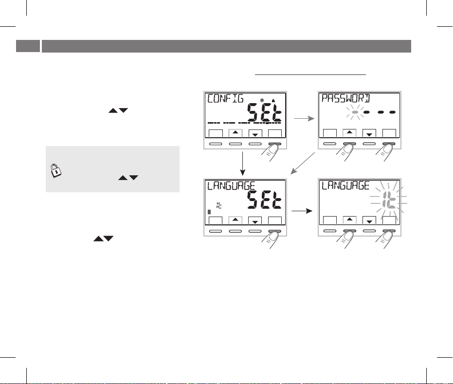
11.1 - ACCESSO AL MENÙ CONFIGURAZIONE
ATTENZIONE: l’accesso al menù configurazione è consigliato in quanto laall’installatore o ad utenti esperti
modifica di alcuneimpostazioni potrebbecompromettere il corretto funzionamentodell’impianto.
Dal normale funzionamento del termostato, accedere ai
menu tenendo premuto tasto« ».Menu
Selezionare con i tasti la voce eCONFIG SEt
confermare con il tasto si accede alla 1° voceOK:
LANGUAGE SEt del menu (vedere cap. 8 l’elenco dei
sottomenu alla voce CONFIG).
Set
0
6810
161820
2 4
SetT
Menù
back
12 14
22
OK
Set
0246810
SetT
Menù
back
12 14
161820
22
OK
Se èstatainserita precedentemente solo
una password installatore,il displaychiede
l’inserimento delle 4 cifre, selezionabili
utilizzando i tasti ; confermarle
singolarmente premendoil tasto« ».OK
11.2 - MODIFICA DELLA LINGUA IMPOSTATA
Visualizzata la voce , premere il tastoLANGUAGE SEt OK
per confermare.
•Utilizzando i tasti scegliere la lingua desiderata
scorrendo trale linguedisponibili:
ITALIANO INGLESE(default)=It , =En,
TEDESCO FRANCESE=,= dE, Fr
SPAGNOLO = ES.
• OK.Confermare premendoil tasto
•Premereiltasto« » peruscire.back
18
1°
Set
0
6810
2 4
SetT
Menù
back
12 14
161820
22
OK
Set
0
6810
2 4
SetT
Menù
back
1°
12 14
2°
161820
2°
22
OK
11 - MENU PER LA CONFIGURAZIONE (installatore)
IT
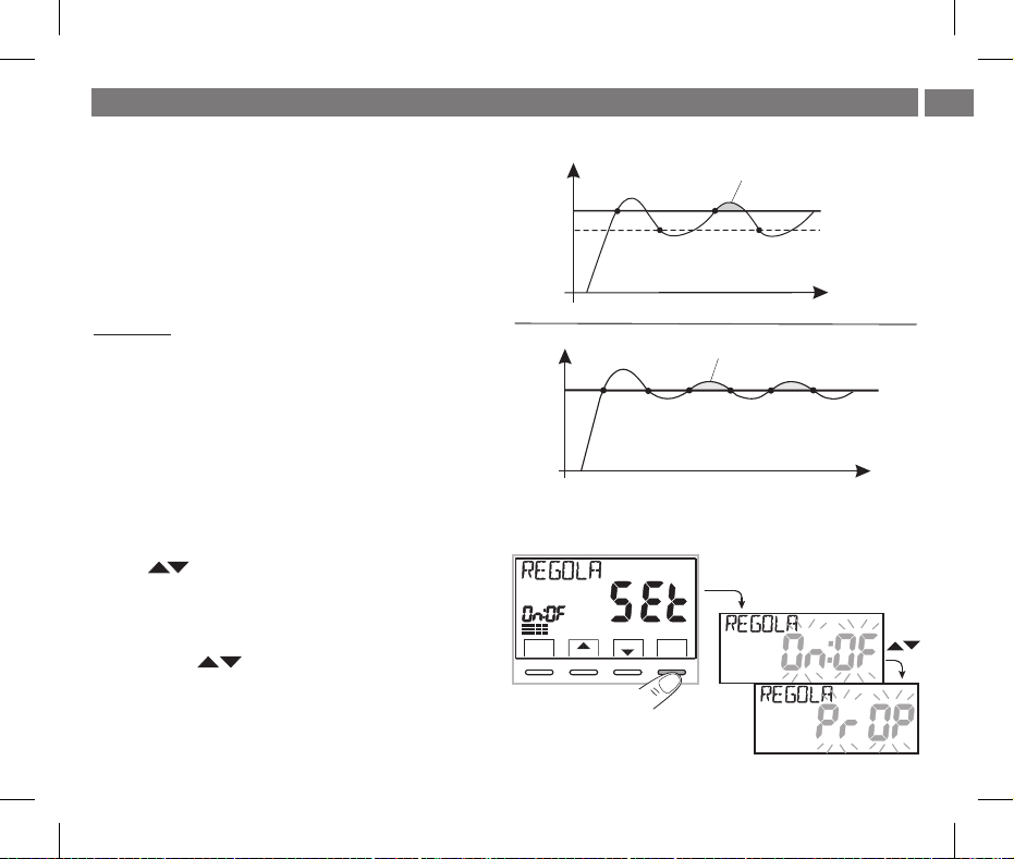
11.3 - TIPO DI MODALITÀ DI REGOLAZIONE DELLA TEMPERATURA
sovratemperatura da inerzia
Il termostato funziona (default) in modo DIFFERENZIALE TERMICO
ON OFF/ con valoredel differenzialetermico(Isteresi)prefissatoa 0,3 °C.
Nota: valori impostabili da0,2 °Ca1,2°C(da0,3°Fa 2,1 °F).
Il valore dell’isteresi deve essere impostato in base all’inerzia termica
°C/°F
T SET
isteresi
OFF
dell’impianto: siconsiglia unvalore bassoper impianticon radiatori(es.
in ghisa) ed unvalore altoperimpianticonFancoil.
esempio tipo di regolazione differenziale
In alternativa alDifferenziale termicoèpossibile regolare latemperatura
in modo ( ); la durata del ciclo èPROPORZIONALE MODULANTE PrOP
impostabile da 7a 20 minuti (impostazione di fabbrica 10 minuti).
Questo sistema permette di mantenere più stabile la temperatura
desiderata, aumentando la sensazione di comfor t per l’utente e
°C/°F
T SET
OFF
risparmiando suiconsumi energetici.
Si consigliaunciclo lungoperimpianti coninerzia termicaalta (radiatori
in ghisa,impiantia pavimento)edun ciclobreve per impianticon inerzia
termica bassa(fan- coil).
esempio tipo di regolazione proporzionale modulante
11.3.1 - SELEZIONE DELLA MODALITÀ DI REGOLAZIONE DELLA TEMPERATURA (DIFFERENZIALE ON/OFF o PROPORZIONALE)
Dal normale funzionamentodel termostato,accedereaimenutenendopremutotasto« » ,selezionareMenu CONFIG Set,confermareconOK.
con itasti selezionarela voce REGOLA Set.
Premereiltasto perconfermare.OK
Sarà possibileselezionarela modalitàdi regolazione dellatemperaturatra
funzionamento , impostazionedi fabbrica,Differenziale termico(On:OF)
o.Proporzionale modulante(PrOP)
Utilizzando i tasti , a modalità di regolazione della
selezionare l
temperatura desiderata. OKEseguita la scelta premere il tasto per
confermare e visualizzarela schermata perl’impostazione dell’ seISTERESI
si è scelto , oppure per l’impostazione del se si è sceltoOn:OF PERIODO
PrOP (vedereparagrafi successivi:11.3.2 e11.3.3).
Set
0
6810
2 4
SetT
Menù
back
12 14
termica del corpo scaldante
ON
sovratemperatura da inerzia
termica del corpo scaldante
OFF
ON
161820
22
OK
OFF
ON
ON OFF
tempo
ON
tempo
19
IT
11 - MENU PER LA CONFIGURAZIONE (installatore)
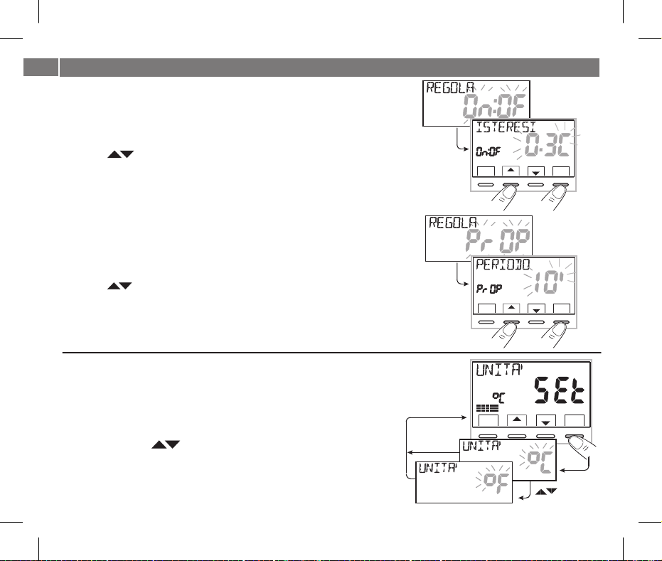
11.3.2 - Impostazione dell’isteresi per il differenziale termico ON-OFF
Dal normale funzionamentodel termostato,accedereaimenutenendopremutotasto« ».Menu
•Attraverso il percorso -> ,CONFIG SEt REGOLA SEt On:OF-> selezionare
quindi premere il tasto
OK.
OK
• inserire ilvalorediisteresidesideratoCon i tasti
(valori impostabili da 0,2 °Ca 1,2°C/da0,3°Fa2,1°F-default0,3°C/0,4°F).
•
•
OKPremereiltasto perconfermare.
backPremereil tasto per uscire.
11.3.3 - Impostazione durata del periodo per il Proporzionale modulante
Dal normale funzionamentodel termostato,accedereaimenutenendopremutotasto« ».Menu
• CONFIG SEt REGOLA SEt PrOP-> selezionareAttraverso il percorso -> ,
quindi premere il tasto .
OK
OK
•Con i tasti inserireladuratadelperiododesiderato
(impostabile da 7 a20 min default 10minutiuti, ).
• OKPremere iltasto perconfermare.
•
backPremereil tasto per uscire.
11.4 - MODIFICA DELL’UNITÀ DI MISURA PER LA LETTURA DELLA TEMPERATURA
Il termostato è predisposto in fabbrica per la visualizzazione delle temperature in gradi Centigradi
(Celsius); sarà possibile passare allascala Fahrenheito viceversacomedaseguenteprocedura:
Dal normale funzionamentodel termostato,accedereaimenutenendopremutotasto« ».Menu
• CONFIG SEt UNITA SEtselezionare ’, OKAttraverso il percorso -> quindi premere il tasto .
•Selezionare l’unità dimisura desiderata:°Co °F,con i tasti
quindi premere il tasto per confermare.
OK
Tuttii setditemperaturaverrannoaggiornatisecondola nuova scala.
•
20
backPremereiltasto per uscire.
OK
OK
Set
0
6810
6810
6810
161820
12 14
22
OK
2°
161820
12 14
22
OK
2°
161820
12 14
22
OK
2 4
SetT
Menù
back
1°
Set
0
2 4
SetT
Menù
back
1°
Set
0
2 4
SetT
Menù
back

11 - MENU PER LA CONFIGURAZIONE (installatore)
11 - MENU PER LA CONFIGURAZIONE (installatore)
11.5 - CORREZIONE LETTURA DELLA TEMPERATURA AMBIENTE
Se perqualsiasi motivo iltermostato deve essereinstallato in una posizionein cui la
temperatura ambiente misurata può esserne influenzata (es. il muro perimetrale
che in inverno è mediamente più freddo e in estate più caldo del resto
dell’abitazione), il dispositivo permettedi correggerecon 2 parametri distinti, siala
temperatura ambiente rilevata in che quellain .modalità Inverno modalità Estate
Dal normale funzionamento del termostato, accedere ai menu tenendo premuto tasto « ».Menu
• CONFIG SEt OFFSETSetAttraverso ilpercorso ->,selezionare lavoce .
Premereiltasto perconfermare.
OK
OFFSET per la modalità inverno ()
Il display alterna icampi vuotidainserire( )conilvaloredellatemperaturaattuale.----
•Utilizzando il tasto -inserire valoripositivi, coniltasto valorinegativi (segno« »).
Correzione possibile -3.0 °C ÷ 3.0 °C(-5.4 °F) (5.4 °F)
default 0.0 °C/°F =
- - - -
Ad ogniselezione il displayproporrà il nuovovalore di correzione(es: 0,6°C) alternatoal
valore di temperatura letto (es:21.2°C).
• OKEseguita la correzione premereil tasto« ».
Il display visualizza ; procedere alla correzionel’OFFSET per la modalità Estate ()
come da procedura soprariportataoppurepremereiltasto peruscire.back
per annullare eventuali correzioni di temperatura precedentemente impostati
riportare OFFSETa .
Set
0
6810
2 4
SetT
Menù
back
12 14
OK
161820
22
OK
OK
11.6 - BLOCCO SET TEMPERATURA MAX e MIN (modalità Inverno ed Estate)
In alcuni casi particolari di installazione del termostato, ad esempio in edifici pubblici, alberghi, ecc., potrebbe essere utile limitare i set di
temperatura massimo e/o minimo, inmodo daevitareimpostazionierratedaparte di personalenon autorizzato(risparmioenergetico).
È possibilelimitare (bloccare) ivalorimassimo,minimo, oentrambi, della temperaturaimpostabile sul termostato.
La limitazione può essere applicata sia alla modalità che allamodalità .Inverno Estate
IT
21

IT
11 - MENU PER LA CONFIGURAZIONE (installatore)
Dal normale funzionamentodel termostato,accedereaimenutenendopremutotasto« ».Menu
•Attraverso il percorso ->CONFIG SEt BLOCCHI SEt OK, selezionare la voce . Premere il tasto per confermare.
In modo sequenziale èpossibile impostareiblocchiditemperaturamassima( ) e/o minima ( ) per lat1comfort t2 economy modalità Inverno
e/o temperatura massima ( ) e/ominima( ) perla .t1 comfort t2economy modalitàEstate
Se non sono presentiblocchi giàinseriti,ildisplaypresentacampivuotilampeggianti( ).----
•Utilizzando i tasti ,
impostare di voltainvoltaivaloriditemperaturadeiblocchidesiderati.
• OKAl termine diogni impostazionepremereiltasto perconfermareepassareallavocedelbloccosuccessivo.
Premendo il tasto ad impulsi si passa da una voce all’altra. Premere il tasto per uscire.OK back
Set
0
6810
2 4
SetT
Menù
back
12 14
161820
22
OK
OK
per annullare eventuali blocchi precedentemente impostati
riportare iset MAX/MIN a .
OK
Regola generale
Se (comfort) impostatarisultasse essa si livellerà a quest’ultimo.la temperatura Set t1 maggiorealbloccomassimoinserito,
Se impostata risultasse essa si livellerà a quest’ultimo.la temperatura Set t o t2 minorealbloccominimoinserito,
Pertuttelealtretemperaturevarrà la seguente regola:INVERNO ( ) = > > - ESTATE( )= <t1 t2 t t1 t2
Durante il funzionamento deltermostato, l’utentenonpotràimpostareun superioreoinferioreaiblocchimaxemin.inseriti.Set t
Il display segnalerà l’impossibilità adeseguire ilcomandovisualizzandolascritta .
22
OK
OK

11 - MENU PER LA CONFIGURAZIONE (installatore)
11.7 - MENU SONDA
In aggiunta alla sonda interna del termostato, è possibile collegare ai morsetti e « (vedere schemi elettrici al cap. 5.4) una sonda67AUX1»
supplementare (opzionale)che puòessere impostataper lalettura dellatemperatura indiverse modalità.
•premere per3 seciltasto ,Menu eattraverso il percorso-> ->CONFIGSEt SONDASet
SONDA NO
SONDA REMOTA
SONDA PAVIMENTO
SONDA ESTERNA
La sonda separata non viene letta, è disattivata (impostazione di fabbrica in prima accensione).
Misura la temperatura di un ambiente in sostituzione della sonda interna al termostato.
Misura la temperatura del pavimento e spegne il carico collegato se supera una determinata soglia impostata.
La termoregolazione degli ambienti viene gestita dalla sonda interna al termostato.
Misura la temperatura esterna all’abitazione senza influire sulla termoregolazione degli ambienti interni.
Selezionare il tipo di sonda desiderato con i tasti e confermare con il tasto OK.
premere iltasto .OK Le funzioni selezionabilisono le seguenti:
IT
161820
Set
0
6810
161820
12 14
2 4
SetT
Menù
back
22
OK
Set
0
6810
2 4
SetT
Menù
Set
0
6810
2 4
12 14
SetT
Menù
back
back
18
16
20
22
OK
18
16
20
22
12 14
OK
Set
0
6810
12 14
2 4
SetT
Menù
back
Possibili segnalazioni di anomalia sul display riguardante la sonda separata
4 trattini lampeggianti = termostato rimosso dalla base relè fissata a parete.
Err lampeggiante = sonda interrotta o in corto oppure nessuna sonda collegata. La termoregolazione viene sospesa.
Valore di inizio o fine scala lampeggiante = la sonda rileva un valore superiore o inferiore al range di funzionamento.
11.7.1 - NESSUN COLLEGAMENTO A SONDA SEPARATA
Se sidesidera disattivare lasondadi temperaturaseparata precedentemente attivaetornare adutilizzare solo
quella standardinterna (default), seguirelaseguente procedura:tasto premuto per 3sece attraversoilMenu
percorso-> -> -> selezionare la voce (NO) eCONFIG SEt SONDA Set SONDA nO
confermare. Premere iltasto peruscire.back
Range di lettura della sonda interna: - 5.0°C +37.7°C (+ 23.0°F +99.9°F)÷÷
premere il tasto perOK
22
OK
Set
0
6810
2 4
SetT
Menù
back
Set
0
6810
2 4
SetT
Menù
back
161820
12 14
22
OK
18
20
16
22
12 14
OK
23

IT
11 - MENU PER LA CONFIGURAZIONE (installatore)
11.7.2 - IMPOSTAZIONE SONDA SEPARATA REMOTA
Si trattadi unasonda remota perrilevare latemperatura inun ambiente diversoda quelloove è installatoil
termostato, adesempioin casodi montaggio nonfavorevole o inlocalinonadatti allalettura e regolazione
della temperatura. La sondaremota haglistessiparametrierangediletturadellasondainterna.
Rangedilettura:-5.0°C÷+37,7°C(+23°F÷+99,9°F).
Sostituisce completamente la sonda interna del termostato e sarà tramite questa sonda remota che il
prodotto regolerà la termoregolazione dell'ambiente.
Effettuato il collegamentoal termostatodellasonda di temperaturaremota, saràpossibileattivarlatenendo
premuto iltasto« » per 3sec.Menu
la voce REMOTA
. Premereiltasto« » perconfermare.OK
Premereiltasto per uscire.back
-> ->CONFIGSEt SONDA Sete attraversoilpercorso -> selezionare
Set
0
6810
161820
12 14
2 4
SetT
Menù
back
Set
SetT
Menù
back
22
OK
OK
11.7.3 - IMPOSTAZIONE SONDA PAVIMENTO
(funzione di protezione da sovratemperatura)
Si tratta di una sonda di temperatura separata e remotabile, adagiata nel massetto di un impianto di
riscaldamento a pannelli radianti sottopavimento, per monitorarne la temperatura e spegnere l’impianto
nel caso in cuila temperaturalettasuperasseunvaloredisogliapreimpostato.
Effettuato il collegamento al termostato della sonda di temperatura separata, sarà possibile attivarla
tenendo premuto il tasto « » per 3 sec.Menu CONFIG SEt SONDA SEt-> -> ->e attraverso il percorso
selezionare la voce PAVIMENT
. Confermare conil tasto .OK
Utilizzando i tasti , definire di temperaturadesiderata (esempio35°C)lasoglia .
Premereiltasto perconfermare.Premereil tasto per uscire.OK back
Range di lettura della sonda a pavimento: + 0.0°C +60.0°C (+ 32.0°F +140.0°F)÷÷
Il superamento del valore 99.9°F (scala Fahrenheit) comporta la soppressione dei decimali.
Il termostato visualizza e termoregola la temperatura ambiente rilevata della sonda interna;
contemporaneamente la sonda separata rileveràanche la temperatura a pavimento,che sarà comparata
con la soglia impostata dall'installatore, per impedire che tale temperatura superi la soglia stessa di
sicurezza. Se ciò dovesse avvenire il termostato interverrà spegnendo l’impianto anche se non si fosse
raggiunta la temperatura impostata; il display segnala tale condizione visualizzando la sigla e, inSet t tP
modo lampeggiante, il valoredella sogliaimpostato.
24
Avviso di superamento della soglia impostata. L’impianto di termoregolazione è disattivato
Set
0
6810
6810
161820
12 14
22
OK
161820
12 14
22
OK
2°
OK
4
2
SetT
Menù
back
,
Set
0
2 4
SetT
Menù
back
1°
Set
SetT
Menù
back

11 - MENU PER LA CONFIGURAZIONE (installatore)
11.7.4 - IMPOSTAZIONE SONDA SEPARATA ESTERNA
Si tratta di unasonda aggiuntivachepermettelaletturadellatemperaturaesterna all’abitazione( ).tE
Non ha funzionidi termoregolazione della temperatura dell’abitazione, cheè gestita dallasonda interna a
bordo del termostato.
Effettuato il collegamento al termostato della sonda di temperatura esterna, sarà possibile attivarla
premendo iltasto per 3 sec. eattraversoil percorso -> -> -> selezionareMenu CONFIG SEt SONDA Set
la voce Premereiltasto per uscire.ESTERNA. Premereiltasto« » perconfermare.
Range di lettura della sonda esterna: - 9.9°C +60.0°C (+ 14.2°F +140.0°F).÷÷
Il superamento del valore 99.9°F (scala Fahrenheit) comporta la soppressione dei decimali.
Nota: in modalità normale funzionamento del termostato, ogni 10 secondi il display alternerà la
lettura della temperatura esterna con il valore di Set di temperatura al momento
impostato.
11.8 - COLLEGAMENTO A CONTATTO ESTERNO PER
ACCENSIONE/SPEGNIMENTO DA REMOTO DEL TERMOSTATO
Prima di abilitare una qualsiasi voce del menu «INGRESSO» elencata successivamente,
assicurarsi di aver collegatoun contattoesternoaimorsetti8e9(AUX2).
È possibile collegare al termostato un dispositivo remoto (es.: programmatore telefonico, interruttore
orario, interruttore) ingradodiattivare/disattivareiltermostatoadistanza.
Dal normale funzionamentodel termostato,accedere aimenu tenendopremuto per3sec. iltasto « » eMenu
attraverso il percorso
Premereiltasto perconfermare.
Possono essere selezionate diverse modalità di funzionamento a seconda del tipo di contatto libero da
potenziale (NA o NC) e del tipo di dispositivo collegato ai morsetti e « » (vedere par. 5.48 9 AUX 2
collegamenti elettrici):
- = Esclusione ingresso per contatto esterno (impostazione di fabbrica);INGRESSO nO
- = per contatto «Normalmente Chiuso» di un Programmatore telefonico;TELEFONO nC
- TELEFONO nA = per contatto «Normalmente Aperto» di un Programmatore telefonico;
- = per contatto «Normalmente Aperto» es.: interruttore;OBBLIGO nA
- = per contatto «Normalmente Chiuso» es.: interruttore.OBBLIGO nC
-> CONFIG SEt Set->selezionare la voce INGRESSO .
OK
OK back
()tE
Set
0
6810
161820
12 14
2 4
SetT
Menù
back
Set
SetT
Menù
back
ogni 10 sec.
Set
0
6810
2 4
SetT
Menù
back
Set
0
6810
2 4
SetT
Menù
back
Nota: per escludere l’ingresso precedentemente
abilitato selezionare con i tasti la schermata
sopra, confermare con il tasto OK.
backPremere per uscire.
12 14
12 14
161820
161820
IT
22
OK
OK
22
OK
22
OK
25

IT
11 - MENU PER LA CONFIGURAZIONE (installatore)
11.8.1 - ATTIVAZIONE / DISATTIVAZIONE CON PROGRAMMATORE TELEFONICO
Effettuato ilcollegamentodel Programmatoretelefonico (opzionale) altermostato, saràpossibilescegliere l’impostazionedel tipo dicontatto NAo
NC presente a bordodel programmatoretelefonico.
Premereil per3sec.seguireilpercorso-> ->tasto ,visualizzata la voceMenu CONFIG SEt INGRESSO SEt
e con i tasti sceglierelavoceTELEFONO nC TELEFONO nA OK backo . Premereiltasto« » perconfermare. Premereiltasto per uscire.
, premere iltasto« » perconfermareOK
Set
0
6810
161820
12 14
2 4
SetT
Menù
back
Set
0
6810
161820
12 14
2 4
SetT
Menù
back
es. Programmatore telefonico (contatto NC)
Chiusura contatto
22
OK
Apertura contatto
es. Programmatore telefonico (contatto NA)
Chiusura contatto
22
OK
Apertura contatto
Funzionamento del termostato
in modalità conOFF antigelot
in modalità t1 COMFORT
Funzionamento del termostato
in modalità t1 COMFORT
in modalità conOFF antigelot
Nota: i comandi di apertura e chiusura contatto sono operativi entro 10 sec.
11.8.1a - Esempio di accensione/spegnimento del
termostato a distanza, collegato a un
programmatore telefonico concontatto NA
(normalmente aperto).
Set
Menù
Es. Programmatore telefonico
contatto NA
- del programmatore (passaggio di stato): con laChiusura del contatto provoca la forzatura nello stato di temperatura t1 COMFORT
visualizzazione dei simboli/setpoint associatie l'icona“ ” fissaad indicarel'arrivodiunaforzatura datelefono.
In seguito saràpossibile cambiaresul postoil modo difunzionamento agendomanualmente sullatastiera del termostato, anche seil contatto del
programmatore telefonico rimarrà chiuso; l'icona “ ” rimarrà accesafissaindicandolostatodel contatto ancora chiuso.
- del programmatore (passaggiodi stato): (par. 7.4- EsclusionedelApertura delcontatto provoca laforzatura nello statodi funzionamento
OFF
termostato) confunzione antigelose nondisattivata; ildisplayvisualizzala scritta (fissa)el’icona“ ” lampeggiante, indicandol'arrivo diOFF
una forzatura datelefono. Inseguitosipotràritornare alnormale funzionamentodeltermostato premendoil tasto ,si spegneràl'icona
“ ” indicandolafinedellaforzaturatelefonica.
Nota: i comandi di apertura e chiusura contatto sono operativi entro 10 sec.
26

11 - MENU PER LA CONFIGURAZIONE (installatore)
11.8.2 - OBBLIGO NA - per contatto normalmente aperto
Scegliendo questa funzione èpossibile collegare un contattoremoto NA chealla sua chiusura disponeil termostato nella modalità (spento)OFF
con temperatura t antigelo, senonèstataesclusaprecedentemente.
In questa condizione agire suitastidel termostato per cambiare lo statodi funzionamento.non sarà possibile
Aprendo il contatto iltermostato riprenderàilmododifunzionamentoattivoprimadella forzatura.
Premereiltasto per 3sec., seguireilpercorso-> -> -> sceglierela voceMenu INGRESSOCONFIG SEt Set
Premereiltasto« » perconfermare. .OK Premere iltasto per uscireback
.OBBLIGO nA
IT
Set
0
6810
161820
12 14
2 4
SetT
Menù
back
22
OK
es. Interruttore
Chiusura contatto
Apertura contatto
Funzionamento del termostato
in modalità conOFF antigelot
modo di funzionamento in corso
Nota: i comandi di apertura e chiusura contatto sono operativi entro 10 sec.
11.8.3 - OBBLIGO NC - per contatto normalmente chiuso
Attenzione: non abilitare la voce OBBLIGO nC senza aver preventivamente collegato ai morsetti 8e9(AUX2)uninterruttore o altro
dispositivo che permetta ilpassaggio distatodamodalità amododifunzionamentoincorsoeviceversa.OFF
Scegliendo questa funzione è possibile collegare un contatto remoto NC che alla sua apertura dispone il termostato nella modalità (spento)OFF
con temperatura t antigelo, senonèstataesclusaprecedentemente.
In questa condizione agire suitastidel termostato per cambiare lo statodi funzionamento.non sarà possibile
Chiudendo il contatto iltermostato riprenderàilmododifunzionamentoattivoprimadella forzatura.
Premereiltasto per 3sec., seguireilpercorso-> -> -> sceglierelavoceMenu CONFIG SEt INGRESSO SEt
Premereiltasto« » perconfermare.OK Premere iltasto peruscire.back
Set
0
6810
161820
12 14
2 4
SetT
Menù
back
22
OK
es. Interruttore
Chiusura contatto
Apertura contatto
Funzionamento del termostato
modo di funzionamento in corso
in modalità conOFF antigelot
Nota: i comandi di apertura e chiusura contatto sono operativi entro 10 sec.
.OBBLIGO nC
27

IT
11 - MENU PER LA CONFIGURAZIONE (installatore)
11.9 - CICLO ANTICALCARE
Se la funzione è attivata, il termostato interviene tutti i giorni dell'anno
(dopo 24h dall’ultimo intervento del relè), per la durata di 2 minuti primi,
attivando il dispositivo comandato: pompa, valvola ecc. allo scopo di
evitare incrostazioni e grippaggicausati dainattivitàprolungata.
Il termostato interviene solo se nelle 24 ore precedenti non è mai
stato attivato il carico collegato.
Dal normale funzionamento del termostato premere il tasto per 3Menu
sec. seguire il percorso-> -> ->, CONFIG SEt SEtPOMPA ON
tasto « » desiderata:OK POMPA ON nO
e coni tasti sceglierela voce
premere il
Set
0
6810
2 4
SetT
Menù
back
(NO) oppure Premereiltasto« » per confermare.POMPAON2'. OK
Premereiltasto per uscire.back
11.10 - REGOLAZIONE CONTRASTO DEL DISPLAY
Sono disponibili 8 livellidi regolazione.Infabbricavieneimpostatoillivello6.
Dal normale funzionamento del termostato premere il tasto per 3 sec.,Menu
seguire il percorso -> -> utilizzando i tastiCONFIG SEt
voce . Premereil tasto perconfermare.
RISALTOSEt OK
Con i tasti selezionare il livello desiderato.
Ad ogni selezione sarà visibile la variazione di contrasto ottenuta.
selezionare la
Set
SetT
Menù
back
Premere il tasto per confermare. Premere il tasto per uscire.backOK
11.11 - RETROILLUMINAZIONE
Consente di attivare o disattivare la retroilluminazione temporizzata del
display.Dal normale funzionamentodel termostato premere iltasto perMenu
3 sec., seguire il percorso -> -> utilizzando i tastiCONFIG SEt
selezionare la voce . Premereiltasto perconfermare.RETROLED SEt OK
Con i tasti scegliere lavocedesiderata:
retroilluminazione temporizzata o retroilluminazionedisattivata (NO).6SEC nO
Premereiltasto per confermare.Premereiltasto peruscire.OK back
Impostazione di fabbrica: retroilluminazione temporizzata 6 sec.
28
OK
OK
Set
0
6810
161820
12 14
2 4
SetT
Menù
6810
22
OK
back
161820
12 14
22
OK
Impostazione di fabbrica in
Set
0
2 4
SetT
Menù
back
161820
12 14
22
OK
prima accensione la funzione
èdisattivata.
Set
161820
1°
12 14
161820
2°
SetT
Menù
back
22
OK
Set
SetT
Menù
back
12 14
12 14
161820
22
OK
22
OK

11 - MENU PER LA CONFIGURAZIONE (installatore)
11.12 - INSERIMENTO E GESTIONE DELLE PASSWORD
Alcune funzioni di questo termostato possono essere protette da una Password
utente ( ) e/o installatore( ), inmodo che possanoesseremodificate soloda chiUt InSt
ne èabilitato. Nella impostazionedifabbricanessuna passwordè attiva.
11.12.1 - INSERIMENTONUOVAPASSWORD
•Dal normale funzionamento del termostato premere il tasto per 3 sec. eMenu
seguire ilpercorso -> ->CONFIGSEt SEtPASSWORD
per accedere alla schermata della creazione di un codice segreto Utente
(PASSWORD SEt Ut), OK,
scegliere la voce
e confermare con per la creazione delPASSWORD SEtInSt OK
codice segreto .Installatore
•Utilizzando i tasti , inserire 4 cifre (esclusi trattini) comprese tra e0000
9999 OK, confermandolesingolarmente conil tasto« ».
Premere il tasto per uscire.back
La password « » consente di accedere alle funzioni disponibili attraverso ilUtente
tasto Se è presente anche unapassword installatore nonsi potrà accedereMenu.
al menù .SEtCONFIG
La password « » consente di accedere a tutte le funzioni del menuInstallatore
« » ) ed anche alle impostazioni .Configurazioni (CONFIG SEt Utente
premere iltasto « »OK->
11.12.2 - MODIFICA O ANNULLAMENTO DELLA PASSWORD
Alla richiesta di accesso Utente o Installatore inserire la password
precedentemente creata;seguendo laprocedurasopradescrittaaccedere alla voce
PASSWORDSEt Ut InSto:
- inserire 4 trattini(- ---)perannullarelapassword
- inserire 4 nuovecifre permodificarelapassword
Informazione riservata solo all’installatore e utente esperto
in casodi passworddimenticata inserireil codicedi ripristino alla richiestadi accessoutente oinstallatore.
Il codice segreto utente o installatore verrà annullato.
,confermare ripremendo oppure con i tasti
esempio:
OK
SetT
Menù
back
OK
OK
SetT
Menù
back
OK
OK
OK
OK
OK
inserire la password utente
come da esempio a lato
OK
OK
IT
29

IT
11 - MENU PER LA CONFIGURAZIONE (installatore)
11.13 - RESTORE (RESET)
IMPORTANTE! L’operazione di RESTORE (Reset) è consigliata
all’installatore o ad utenti esperti in quanto, con questa operazione, molte
impostazioni precedentemente eseguite, anche secondo la tipologia
dell’impianto, verrannoperse.
• tasto per 3 sec, seguendo il percorsoMenuL’operazione è attuabile premendo il ->
CONFIG SEt RESTORE SEtselezionare la voce->: utilizzando itasti confermando
con il tasto .OK
Il display proporrà lascelta traeffettuareilrestore » enon effettuarlo ».«SI «NO
• i tasti OKPer scegliereutilizzare , quindipremere iltasto per confermare.
• NO RESTORE SEtConfermando il display usciràdalla funzione tornandoalla videata iniziale.
Premereiltasto per uscire.back
• SI RESTORE per 3 secondiConfermando sarà visualizzata la scritta « » , quindi il sistema si
riavvierà posizionandosi sulla schermata dellaselezione dellalingua.
• selezionare lalingua desiderata.
•
backPremere 2volteiltasto per uscire.
•Il termostato sidispone innormalefunzionamento.
Nota: iltermostato ripristina molteimpostazioni di fabbrica (default)ad eccezione di alcunevoci
particolari cheutilizzanol’ultimovaloreimpostato(vederetabellariassuntivaalcapitolo2).
l’operazione diRESTORE cancella eventualepassword utente e/o installatore inserita.
Premereiltasto per confermare.OKCon itasti
OK
Menù
back
SetT
OK
OK
OK
SetT
Menù
back
OK
11.14 - INFORMAZIONI SOFTWARE DI SISTEMA
Dal normalefunzionamentodeltermostato premereil tasto per 3sec.Menu selezionare e
confermare con la voce ->,OK CONFIG SEt utilizzando i tasti visualizzare la
voce per ottenereinformazioniinerentialfirmwareinstallato.INFO SW
Premere iltasto per ritornare almenù precedente oppure premere peruscire daiback OK
menù.
Questo parametro è utilein casodirichiestadiassistenzatecnica.
30
Esempio:
Versione Firmware
Set
Revisione Firmware
0
2 4
6810
12 14
161820
22
OK
OK

12 -
EVENTUALI INCONVENIENTI E SOLUZIONI
IT
INCONVENIENTE
Il display del termostato è spento
Sul display è comparso
il simbolo lampeggiante
Sul display compare solamente
il simbolo fisso
Visualizzazione sul display della
scritta: NO RELÈ
Il termostato funziona ma l’impianto
non viene attivato
La temperatura oscilla troppo tra
caldo e freddo
In funzionamento OFF ( Inverno) il
Set di temperatura antigelo non è
visualizzato
CAUSA
Pile non installate
Polarità pile errata
Pile esaurite
Le pile stanno per esaurirsi
Le pile sono esaurite
Eccessivo serraggio delle viti che
fissano la base del termostato alla
scatola rettangolare o tonda
incassata a muro
Il termostato è staccato o non
correttamente fissato alla base a parete
Manca tensione all’impianto
Il termostato non è collegato
correttamente
Il termostato non è impostato
correttamente per iltipo diimpianto
La temperatura antigelo è stata
esclusa
SOLUZIONE
Controllare che lepile sianoinstallate
Verificare la polarità delle pile
Sostituire le pile
Sostituire le pileentro 15giorni
Sostituire le pile
La base fissata a parete, non deve
presentare incurvature dovute all’eccessivo
serraggio delle viti.
Allentare le viti e verificare dopo il montaggio
del termostatola scomparsa dal displaydella
scritta NO RELÈ
Togliere e rimettere il termostato alla base a
parete come indicatoal paragrafo 5.5
Controllare che l’interruttore o il differenziale
di protezione nonsiano inOFF
Contattare l’installatore
Contattare l’installatore
Impostare latemperatura antigelo seguendo
le indicazione riportateal paragrafo10.2
31

CONTENTS
DEVICE PRESENTATION
WARNINGS
1 - TECHNICAL DATA
2 - FACTORY SETTINGS
3 - KEY FUNCTIONS
EN
4 - DISPLAY FEATURES
5 - INSTALLATION
5.1 - Overall dimensions
5.2 - Installation example
5.3 - F
astening the wall base
5.4 - Electrical connections
5.5 - Procedure to fasten or remove the
thermostat from the wall base
5.6 - Signalling batteries low or down
5.6.1 - Inserting or replacing batteries
6 - START THE THERMOSTAT
7 - USE OF THE THERMOSTAT
7.1 - Temperature adjustment from COMFORT to ECONOMY
(energy saving) and vice-versa
7.2 - Modification of T Set temperature set
7.3 - Temperature control pause
7.4 - OFF (disabling the thermostat)
8 - STRUCTURE OF THE MAIN MENUS (use and configuration)
9 - ACCESS TO MENUS
10 - USER MENU
10.1 - Set WINTER or SUMMER mode
10.2 - Modification or disabling of set antifreeze temperature
10.3 - USER PASSWORD Menu (user)
10.3.1 - Entering the user password
10.3.2 - Password modification or cancellation
32
page 33
page 33
page 34
page 35
page 36
page 37
page 38
page 38
page 38
page 38
page 39
page 40
page 41
page 41
page 42
page 43
page 43
page 43
page 43
page 44
page 44
page 45
page 46
page 46
page 46
page 47
page 47
page 47
ENGLISH
11 - CONFIGURATION MENU (installer)
11.1 - Access to configuration menu
11.2 - Change set language
11.3 - Type of temperature adjustment mode
11.3.1 - Selection of the temperature adjustment mode
(differential on/off or proportional)
11.3.2 - Setting hysteresis for thermal differential ON-OFF
11.3.3 - Setting period duration for modulating Proportional
11.4 - Change unit of measure for temperature reading
11.5 - Correction of room temperature reading
11.6 - Max and min set temperature lock (winter and summer mode)
11.7 - Probe menu
11.7.1 - No connection to separate probe
11.7.2 - Setting separate remote probe
11.7.3 - Setting floor probe
11.7.4 - Setting separate external probe
11.8 - Connection to external contact for remote
thermostat switching on/off
11.8.1 - Activation / disabling with a Telephone Programmer
11.8.2 - NO Duty - for normally open contact
11.8.3 - NC Duty - for normally closed contact
11.9 - Descaling cycle
11.10 - Display contrast adjustment
11.11 - Backlighting
11.12 - Entering and managing password
11.12.1 - Entering new password
11.12.2 - Password modification or cancellation
11.13 - Restore (Reset)
11.14 - System software information
12 - POSSIBLE PROBLEMS AND SOLUTIONS
page 48
page 48
page 48
page 49
page 49
page 50
page 50
page 50
page 51
page 51
page 53
page 53
page 54
page 54
page 55
page 55
page 56
page 57
page 57
page 58
page 58
page 58
page 59
page 59
page 59
page 60
page 60
page 61

PRESENTATION
Dear Customer, thank you for choosing our product.
The thermostat,suitable forall heatingand/or coolingsystem,is fitted witha largeandclear backlit displayto keepallits functions undercontrolin
real time.The fundamentalfeature is itseasy touse menunavigation, which makes itextremelyuser-friendly despite itscomprehensive rangeof
functions. The thermostat isfactory-set to adjust temperature in aDifferential ON/OFF mannerand hysteresis canbe set from0.2°C to 1.2°C to
adapt to the thermal inertia of your specific installation. Alternatively, modulating Proportional operation may beselected with settable duration
cycles (from7 to20minutes): this systemensures thedesiredtemperature ismaintained morestable,increasing user comfortand isparticularly
suitable for installations with high thermal iner tia such as, for instance, for underfloor radiant panels. The set temperature scale is in degrees
Centigrade (Celsius) with theoption to calibrate roomtemperature measurement setting a correction value (from -3to +3 °C). The thermostat
can be connected to a separate remote controllable temperature probe (optional) which may then be set according to one's installation needs:
remote, floor, external. Special attention was devoted to energy saving: pausing for household cleaning, optional Set temperature (MAX/MIN)
lock, adjustable anti-freeze temperature value, control through an external contact (e.g. optional telephone programmer), are conducive to
avoiding wasting energy withconsequent savings.Seethefollowingpagesforadescriptionoftheseaswellasofotherfeatures.
WARNINGS!
Read this manual carefully before using the product as it provides important guidelines regarding safety, installation and use.
The manual mustbe preserved with carefor futurereference.
The installation andelectrical connectionofthethermostat mustbe implementedbyqualifiedpersonnel and inconformity
with current lawsand regulations.
The thermostat is not intended for use by persons (including children) with reduced physical, sensory or mental capabilities, orby
those with a lack of experience and knowledge of the instructions, unless they are supervised or have received the necessary
instructions concerninguseofthedevice by aperson responsiblefortheirsafety.
Children should besupervisedtoensurethat they donot playwiththedevice.
-5 °C or+37.7 °CIf (+23°F or +99.9 °F)roomtemperatureflashes on thedisplay,the measured temperatureis beyondthescale.
"Err"If flashesonthedisplay,it indicatesfaultyprobe: any temperaturecontrol activityissuspended.
N.B.: the producthas beentested and its characteristics areguaranteed whenalkaline DURACELL or ENERGIZER batteriesare used.
alkalineUse2stilo 1.5V batteriestype AA(LR6).Batteriesnot included.
If necessary,gentlyclean the thermostatand thedisplaywith a soft,dry cloth.
The manufacturer reservestherighttointroduce any technicaland/or constructive changes deemednecessary, withno prior notice.
EN
33

1 - TECHNICAL DATA
Power supply:
Autonomy:
Battery life after the "battery low" symbol starts
flashing on the display:
White color backlight:
Type of action, disconnection and device:
EN
Type of output:
Software:
Rated impulse voltage:
Cross-section of wires to terminals:
Input for remote contact ON/OFF:
Input for separate remote probe:
Type of insulation:
Degree of protection:
Pollution rating:
Number of temperature levels:
Ambient temperature display range:
Floor probe threshold display range:
External probe display range:
Relay ON signal:
Room temperature indicator resolution:
Temperature Set adjustment range (t1/t2/t3):
Setting temperature Set:
Temperature correction (Offset):
Antifreeze temperature: (t ):
Type of temperature adjustment:
- DIFFERENTIAL ON/OFF (default)
- Proportional with control period
Thermal gradient:
Temperature reading tolerance:
Operating temperature limits:
Storing temperature limits:
ErP classificaenergy tion:
Reference regulations for CE markings:
34
n° 2 batteries 1,5 V type AA (LR6)Alkaline
Approx. 2 years
Approx. 15 days
timed 6 sec. (default) / always off
1 / B / U / Electronic
voltage free relay with COM / NO / NC changeover contact,
max 5(3)A/250 V ~
class A
4 kV
22
1,5 mm ÷ 2,5 mm
for NO or NC contact free from potential
yes - probe may be set depending on use: remote, floor, external
class II
I30P
normal
n° 2 « = COMFORT», « = ECONOMY» + t antifreezet1 t2
- 5.0 °C ÷ + 37.7 °C (+ 23 °F ÷ +99.9 °F)
- 0.0 °C ÷ + 60.0 °C (+ 32 °F ÷ +140 °F)
- 9.9 °C ÷ + 60.0 °C ( +14.2 °F ÷ +140 °F)
Flashing + ON (winter) or + ON (summer)
0.1 °C (0.1 °F)
+5 °C ÷ +37.7 °C (+41.0°F ÷ +99.9 °F) limitable
adjustable by 0.1 °C / 0.1 °F sets
adjustable from -3.0 °C (5.4°F) to +3.0 °C (5.4°F) default 0.0 °C/0,0 °F
adjustable + 5 °C ÷ <t2 (41,0 °F ÷ <t2) default 6 °C (42.8 °F)
adjustable from 0.2 °C to 1.2 °C (from 0,3 °F to 2.1 °F) default 0,3 °C (0,4°F)
cycles adjustable from 7 to 20 minutes (default 10 minutes)
max 1°K / 15 min
± 0,5°C (± 0,9°F)
0 °C ÷ +45 °C
-10 °C ÷ +60 °C
ErP Class I; 1% (Reg. EU 811/2013)
LVD - EMC EN60730-2-7 EN60730-2-9

2 - FACTORY SETTINGS
The data enteredin thethermostat called «FACTORY SETTINGS» refer tooperation definedas«Standard».
The following chaptersdescribe allcustomisablefunctions, in ordertosatisfyany ambient comfort need.
FACTORY SETTINGS TABLE (default)
Parameter
Language
Active season
Temperature unit of measure
Set t1 COMFORT Winter
Set t2 ECONOMY Winter
Set t antifreeze (Winter)T
Set t1 COMFORT Summer
Set t2 ECONOMY Summer
Temp. locks Winter
Temp. locks Summer
Temp. adjustment mode
Differential hysteresis
Modulating proportional
Modulating period
Room temp. correction
Room temp. correction
Anti-scale protection cycle
Display contrast
Display back-lighting
Remote Probe
External Input
User Password
Installer Password
Password reset code
Default
IT (Italian)
Winter
°C (celsius)
20.0°C
18.0°C
6.0°C
24.0°C
27.0°C
Disabled
Disabled
DIFF. ON/OFF
0.3°C
Prop (not active)
10 min. (not active)
0,0 °C
0,0 °C
Disabled
Level 6
Timed 6 sec.
(not active)
(not active)
none
none
0927
Restore «reset»
To confirm
Default
Last value
Default
Default
Default
Default
Default
Default
Default
Default
Default
Default
Default
Default
Default
Last value
Default
Default
Last value
Last value
Default
Default
Default
RESTORE «Installer RESET»
Restore manyfactory settings(default)
RESTORE brings the thermostat back to factory settings with the
exception of some items as shown in the table; to perform the
operation follow the instructionsin paragraph11.13.
RESTART
It does not cancel the entered settings
Should thethermostatfeaturemalfunctioning, wrong displaysor other
incorrect conditions,performa .«Userreset»
Simultaneously press for 4 secs.the and keys.Menu
The thermostat resumesnormal operation.
Set
SetT
Menù
back
Press simultaneously for 4 seconds
Set
0
6810
2 4
SetT
Menù
back
12 14
161820
22
OK
EN
35

3 - KEY FUNCTIONS
Backlit display
Touching any key activatesback-lighting, displayingthe
words selection and navigation, press the desired key
within 6 sec. to vary the settings (touching any key
reactivates a 6secs. time-out).
EN
Set
Note: more particularbutton functions are described
in the specificparagraphs.
Multifunction Key Menu/back,
A
its use changes depending on function or active menu:
Menu = press briefly to switch temperature from comfort to economy and vice-versa,
press and hold (3 sec.) access to menus
back = exit from menusgo back to previous item,
B
C
D
36
increases the desired Set temperature;Key
navigation through the menus: to increase a setting value;
Key decreases the desired Set temperature;
navigation through the menus: to decrease a setting value;
Multifunction Key
thermostat in OFF (disabled temperature control)
current program pause for household cleaning
access to selected menu / confirm function or set value (within the menus)
OK
OK
Menù
back
A
SetT
OK
B
C
D
Press the pulse arrow key to
increase/decrease per unit
and keep pressed to
increase/decreaserapidly.

4 - DISPLAY FEATURES
5
6
4
3
Set
2
1
Enabling thermostat from remote control
1
Display Set temperature
2
Currently active set temperature depending on the desired setting:
3
Comfort or Economy (saving) or antifreezet1 t2 t
Current program pause (example: for household cleaning)
4
Info and thermostat operating mode, menu items
5
Batteries low signal
6
Cooling mode ( Summer) active
7
Signalling operating user = and flashingON
8
8
Signalling operating user = and flashingON
Heating mode ( Winter) active
9
8
Detected room temperature
10
T
T
SetT
Menù
back
T
(e.g. boiler on)
(e.g. conditioner on)
8
7
9
10
EN
OK
Note: further displays
are described in the
specific operation
paragraphs
37

5 - INSTALLATION
5.1 - DIMENSIONS
EN
128
88
26
5.2 - INSTALLATION EXAMPLE
h 1,5 m
Install the thermostat preferably at a height of 1.50 to 1.60 m from the
floor,far fromsources ofheat, air inlets,doors orwindows andanything
that may alter itsoperation.
38
5.3 - FASTENING THE WALL BASE
! Switch off mainspower 230V~todevice
! Fasten thebase ofthe thermostat with the screwssupplied: tothe
wall, to the rounded or rectangular recessed box via the relative
paired holes .A
A
A - base fastening holes: wall-mounted, round or rectangular
recessed box
B - wire passage from corrugated tubes, round or rectangular
recessed box
C - thermostat hooking teeth
D - thermostat fastening slot
E - screws to fasten the wall base to the rectangular or round
recessed box.
Toensure thethermostat is fittedcorrectly to the
wall-mounted base, the latter must not be bent
due to the screws being tightened too much to
the rounded or rectangularrecessed box.
C
B
D
A
E

5 - INSTALLATION
5.4 - ELECTRICAL CONNECTIONS
Important: the installation and electrical connection of the devices and appliances must be implemented by qualified
personnel and in conformity with current laws and regulations. The manufacturer declines all liabilityin connection with the
use of productssubject tospecialenvironmentaland/or installation standards.
Disconnect the 230V~ mains voltage that powers the devices to be controlled
Relay terminals
! connect the device to be controlled to
the terminals
1 - common (C)
- normally closed contact (NC)2
- normally open contact (NO)3
Examples of electrical connections
Connection to a boiler
AUX 1
AUX 2
AUX 1 Terminals (remote probe)
! terminals and may be connected67
to a separate temperatureprobe
!(see paragraph 11.7 to setthe probe)
Note: maximum cable length 4 m
NO
C
NC
1239876
AUX 2 Terminals (remote contact)
! terminals and may beconnected89
Connection to a motorized valve
AUX 1
AUX 2
to a telephone programmer (or
switch) for remote thermostat
enabling (see paragraph 11.8 for
external contact setting)
NO
C
NC
1239876
230V~
N
EN
L
probe (optional)
Separate temperature
Contact for remote
thermostat control
example:
Telephone
programmer
(optional)
BOILER
probe (optional)
Separate temperature
L
230V~
N
Contact for remote
thermostat control
example:
Telephone
programmer
(optional)
closes
opens
LOAD
M
230V~
39

5 - INSTALLATION
5.5 - PROCEDURE TO FASTEN OR REMOVE THE THERMOSTAT TO/FROM THE WALL-MOUNTED BASE
After havingmade theelectricalconnections:
! Apply the terminal cover to the base, securing it to
hook .E
! To remove the cover, use a small screwdriver on
hook for leverage.E
EN
E
C
C
1°
D
Hook the thermostat to the wall base in teeth .C
Then press the thermostat at the bottom to complete fastening in slot .D
Removing the
Convenient programming
All setting operations may be performed before
fastening the device to the wall base; this means
setting may be carried out while comfor tably
seated.
The flashing indication with fixed winter orON
summer symbol and the item indicatesNO RELAY
that the thermostat isdetached fromthewallbase.
Should thermostat setting take place before fastening to wall base, upon
completing installation the indication (off or flashing) on the displayON
might notcorrespond tothe actualrelaystatus.
Within after fasteningthe thermostat tothe wallbase,1minute atthe most
the relayactivates withthe indication (off or flashing) displayed.ON
40
D
Unhook the thermostat from the
wall base, using a screwdriver in
the specific slot ( ) in the lowerD
part of the device for leverage,
then turn toremove it.
thermostat
from the wall base
3°
2°

5 - INSTALLATION
5.6 - SIGNALLING BATTERIES LOW OR DOWN
When the symbol blinks, this indicates thatthe batteriesare running out
and as from thismoment thereare15daystoreplacethem.
Note: the backlight of the display is automatically deactivated.
If the discharged batteries are not replaced within this time the display will
completely turn off.
All thermoregulation is suspended and all settings are saved to be restored
when the new batteriesare inserted.
5.6.1 - INSERTING OR REPLACING BATTERIES
Unhook the thermostat fromthe wallbase(seepreviousparagraph)
Insert thebatteries,respectingthepolarity.
Hook and fix thethermostat tothewallbase
(see previous paragraph)
Set
Attention: battery life may be more than 2 years.
However, it is recommended to replace them at least
every 24 months to avoid them running out when you
are away (e.g.Christmas holidays,etc.)
ONLYUSE GOOD QUALITY ALKALINEBATTERIES
(Duracell or Energizerbatteries arerecommended)
3V dc
2 x 1,5Vdc LR6 - AA (not included)
Dispose offlatbatteries inappropriate containers and
as required by the environmental protection
regulations.
EN
41

6 - START THE THERMOSTAT
Upon first inserti the batterieson of , thethermostat performs a lamp-test by switching onall displaysegments, displaying theinstalled
software versionfor afew seconds When thisphaseis over,the thermostatasks to selectthe languageofuse..
Select the desired language by scrolling through the
EN
Set
0
back
Menù
6810
2 4
SetT
12 14
161820
1°
Winter mode (heating)
ON + flashing = e.g. operating boiler
Set
22
OK
2°
0
24
SetT
Menù
back
6810
4
Press twice
12 14
161820
the back key
available languages usingthe keys.
Confirm pressingthe key.
The selectable languagesare:
22
ITALIAN ENGLISH FRENCH(default) ==,=,
OK
Fr dE ES
,=GERMAN SPANISH=, .
OK
It En
Press2time the key.back
Set
The thermostat isoperative, Winterdisplaying: «heating»mode, thetemperature Set at
20°C COMFORT, roomtemperaturedetected.
From normal thermostatoperationin stand-by,pressing a keylightsup the display(unlessback-lighting hasbeendisabled) and
the words selectionand navigationappear.Within 6 secs.,a variationis made thesecond timethedesired keyis pressed.
See use ofthe thermostatto the nextchapter.
42

7 - USE OF THE THERMOSTAT
7.1 - MODIFICATION of temperature from COMFORT to ECONOMY
(energy saving) and vice-versa
Press the MENU key briefly
Set
Set
WINTER= heating (factory setting)
With COMFORT temperature
Menù
SetT
Menù
SetT
7.2 - MODIFICATION OF T TEMPERATURESet SET
Directly press the keys.
The thermostat allows temperature values that satisfy the following
conditions:
Winter: t1 t2 tgreater than or equal to greater than or equal to
Summer: t2 t1greaterthanor equal to
Set
SetT
In the presence of max and min. temperature locks (see
paragraph 11.6) it is not possible to set a higher or lowerSet t
than the entered locks. The display will signal impossibility to
perform theoperationbydisplaying .
7.3 - (example for household cleaning)
TEMPERATURE CONTROL PAUSE
Every time the keys are pressed, it changes by 0.1 degrees;or
pressing and holding enables you to scroll through the values rapidly.
Range: +5 °C to +37,7°C (+41,0°F ÷ 99,9°F).
Pressing the key connected user will switch off for a max 3hour periodduringwhich thethermostat will enterantifreezemode
().t
After 3hours thethermostat temperaturecontrol willresume.
It ispossible to restarttemperature controlbefore the 3hours have
Set
SetT
Menù
elapsed, press « »:theword disappears.back «CLEANING»
Note: in the eventantifreeze temperaturehasbeenpermanentlydisabled
or in "Summer" operation,the connecteduser(e.g.boilerorairconditioner)willremaindisabledfor3hoursmaximum.
Set
SetT
Set
SetT
back
EN
43

7 - USE OF THE THERMOSTAT
7.4 -
OFF (disabling the thermostat)
This setting has thepurpose oflockingthermostatfunctions
when heating or coolingmust remainoff.
1- In «CLEANING» mode , press the button(par. 7.3)
briefly to set the thermostat to and consequentlyOFF
EN
«Switch off the system».
2- Thedisplay shows , toindicate thatthe thermostatis disabledand allfunctions are inactive;theOFF
display only shows room temperature reading, the descaling function, if enabled and (in WINTER
mode) the temperature Setplus theantifreezeprotectionsymbol .t
in WINTER mode with antifreeze temperature disabled or in Summer mode, the symbol will nott
be visible.
in the event of low batteries, the symbol will flash on the display.
3- to reactivatethethermostatPresskey .
Set
SetT
back
Set
8 - STRUCTURE OF THE MAIN MENUS (use and configuration)
The Menus are arranged in sequential order
User Menu:
1 SEASON (Winter or Summer mode)
2 SET TEMP
(modification or disabling of Set antifreeze temperature)
T
3 USER PASSWORD(set user password)
Installer or skilled user menu:
4 CONFIGUR
- LANGUAGE (selection of the desired language)
- RULE (selection of temperature control mode)
44
- UNIT (selection of temperature unit of measure °C/°F)
- OFFSET (correction of detected room temperature)
- BLOCKS (it lets you limit the value of set temperature points)
- PROBE (setting a remote temperature probe)
- INPUT (setting an external contact for remotely enabling / disabling
the programmable thermostat)
- PUMP ON (disabling / enabling the descaling function)
- CONTRAST (to change display contrast)
- BACKLIGHT (to enable/disable display backlighting)
- PASSWORD (to restrict the use of user and/or installer
- RESTORE (RESET operation)
functions of the thermostat)
- INFO SW (information about the firmware version installed)
18
20
22
OK

9 - ACCESS TO MENUS
Fromnormal thermostat operation,press the key for3sec . toaccessthefirstavailablemenu.Menu s
Or,if asecretuserand/orinstalleraccesscode , followthestepsbelowtoaccesstheuserorinstallermenus.has been previously entered
main screen
with the user and installer password
for
3 sec .s
Set
Menù
SetT
with user password only
Set
0
6810
2 4
SetT
Menù
back
12 14
161820
22
OK
1°
password entry example
Set
0
6810
2 4
SetT
Menù
back
no password entered
1°
Set
0
6810
2 4
SetT
Menù
back
12 14
12 14
161820
161820
2°
22
OK
22
OK
Set
0
6810
2 4
SetT
Menù
back
1°
the 1st user menu is accessed after
entering the user password
(see next paragraph)
12 14
161820
2°
22
OK
Set
0
6810
2 4
SetT
Menù
back
The keys areusedtoscrollthroughthemenus:press toentertheselectedmenu,pressOK back
to goback to thepreviousitem.Settings inthe menus mustbeconfirmed bypressing the key whereOK
required, otherwise, after 3 minutes have elapsed, the thermostat goes back to normal stand-by
operation and changes willnot besaved.
Set
0
6810
2 4
SetT
Menù
back
12 14
161820
22
OK
EN
2°
is displayed
for a few seconds after
pressing the key toOK
12 14
161820
Set
0
2 4
SetT
Menù
back
22
OK
the 1st menuCONFIGUR
password (see par 11.1)
6810
12 14
indicate incorrect
password.
item is accessed after
entering the installer
161820
22
OK
45

10 - USER MENU
10.1 - SET WINTER OR SUMMER MODE
From normal thermostat operation, access the menus by
pressing and holding the« » key.Menu
Under item confirmwith .SEASON SEt OK
Select with the keys the WINTER (heating) or
EN
SUMMER (cooling) mode andconfirm withOK.
Pressthe keytoexit.«back»
10.2 - MODIFICATION OR DISABLING OF SET ANTIFREEZE TEMPERATURE
From normal thermostat operation, access the menus by
pressing and holding the« » key.Menu
Use the keys to select item .SET TEMP Set
Press to confirm.OK
The screen displays .ANTIFREEZE
Press to confirm.OK
Use the keys tosetthedesiredantifreezetemperature.
Every time the keys are pressed, it changes by 0.1 degrees;or
pressing and holding enables you to scroll through the values rapidly.
Range: +5 °C a +12°C
Todisable antifreeze temperature t , go below+5.0°C .(41.0°F)
Set
Confirm with Press the key to exit.OK. «back»
46
Set
disabled antifreeze temperature
T
default:
0
6810
6810
6810
6810
161820
12 14
161820
12 14
12 14
12 14
Set
0
6810
2 4
SetT
Menù
back
Set
0
6810
2 4
SetT
Menù
back
12 14
12 14
161820
161820
22
OK
22
OK
2 4
SetT
Menù
back
0
2 4
SetT
Menù
back
Set
0
2 4
SetT
Menù
back
Set
0
2 4
SetT
Menù
back
1°
161820
161820
2°
22
OK
22
OK
22
OK
22
OK

10 - USER MENU
10.3 - USER PASSWORD Menu
10.3.1 - Entering the user password
No code is set in the factory configuration.
Fromnormal thermostatoperation, accessthe menus by
pressing and holding the« » key.Menu
1- Select item with the keysUSER PASSWORD Set
and confirm with .OK
2- Use the , keys enter 4 digits (dashes not
included) between and , individually0000 9999
confirm themwith «OK».
The thermostat entersnormal operation.
From now on, the password will berequired for any
variation on the thermostat.
10.3.2 - Password modification or cancellation
Press and enter the previously set password; follow theMENU for 3 secs.,
procedure described above to accessthe menu:User PASSWORDSEt
- set 4 hyphens(- ---),thepasswordwillbecancelled,
- set another numberand itwillbemodified.
0246810
SetT
Menù
back
Set
0246810
SetT
Menù
back
1°
12 14
12 14
161820
161820
2°
EN
22
OK
Set
0246810
SetT
Menù
back
22
OK
1°
esempio inserimento di una password
Set
0246810
SetT
Menù
back
12 14
12 14
161820
2°
161820
22
OK
22
OK
47

11 - ACCESS TO CONFIGURATION MENU (installer)
11.1 -
ACCESS TO CONFIGURATION MENU
ATTENTION: access to the configuration menu is recommended since thefor the installer or experienced users
modification ofsome settingsmight affectcorrect systemoperation.
From normalthermostat operation,accessthe menusby
pressing and holding the« » key.Menu
EN
Select withthe keys the item andCONFIGUR Set
confirm with access the 1st item ofOK: LANGUAGE SEt
the menu(see chapter 8the list of sub-menusto the item
CONFIGUR).
If only an installer password was entered
the display requests entering the 4 digits,
which may be selected using the ;
keys; individually confirm themwith «OK».
Set
0
6810
161820
2 4
SetT
Menù
back
12 14
22
OK
Set
0246810
SetT
Menù
back
1°
12 14
161820
2°
22
OK
Set
0
6810
2 4
SetT
Menù
back
11.2 - CHANGE SET LANGUAGE
When is displayed,press to confirm.LANGUAGE SEt OK
Set
0
6810
2 4
SetT
Menù
back
12 14
161820
22
OK
•Use the keys to select the desired language
scrolling through available ones.
•Confirm bypressing OK.
1°
The selectable languagesare: (default) = , =ITALIAN ENGLISH FRENCH GERMAN SPANISH= It , = En, Fr = dE, ES.
•Pressthe« » keytoexit.back
48
12 14
161820
2°
22
OK

11 - ACCESS TO CONFIGURATION MENU (installer)
11.3 - TYPE TEMPERATURE ADJUSTMENT METHODS
The thermostatisfactory setto work in modeTHERMALDIFFERENTIAL
ON/OFF with a presetthermal differentialvalue(Hysteresis)of0,3°C.
Note: adjustable from 0,2°C to1,2°C(from0,3°Fto2,1 °F).
The hysteresis value must be set according to the system's thermal
inertia; a low valueis recommendedfor systemswith radiatorsmade of
e.g. cast iron anda highvalueforsystemswithfancoils.
As opposed tothe thermal differential,the temperature canbe adjusted
MODULATING PROPORTIONALLY (PROP) setting cycles from 7 to 20
minutes (default 10 minutes).
This system maintains the desired temperature more stable, whilst
increasing the user's comfort sensation and saving on energy
consumption.
A longcycle isrecommendedforsystems with highthermal inertia (cast
iron radiators, floor systems) and a short cycle for systems with low
thermal inertia(fancoils).
11.3.1 - SELECTION OF THE TEMPERATURE ADJUSTMENT MODE (DIFFERENTIAL ON/OFF OR PROPORTIONAL)
Fromnormal thermostat operation,access themenusbypressingandholdingthe« » key,select press to confirm.Menu OKCONFIGUR Set,
With thekeys selectlaitemRULESet.
Press to confirm.OK
It will be possible to select temperature adjustment mode between
Thermal differential (On:OFF) Modulatingfactory setting or
proportional (PrOP)operation.
Use the
After making your choice press to confirm and display thescreen to setOK
HYSTERESIS On:OFF, PERIODif you haveoptedfor or to set the if you have
opted for (seenext paragraphs: 11.3.2and 11.3.3).PrOP
keys to select the desired temperature adjustment mode.
°C/°F
T SET
hysteresis
OFF
example of differential adjustment
°C/°F
T SET
OFF
example of modulating proportional adjustment
Set
0
6810
2 4
SetT
Menù
back
12 14
thermal inertia over temperature
of the heating element
ON
ON
161820
OFF
thermal inertia over temperature
of the heating element
ON OFF
OFF
22
OK
ON
EN
time
ON
time
49

11 - ACCESS TO CONFIGURATION MENU (installer)
11.3.2 -Setting hysteresis for thermal differential ON-OFF
Fromnormal thermostat operation,access themenusbypressingandholdingthe« » key.Menu
•Through the path then press .CONFIGURSEt-> RULE SEt -> On:OFselect , OK
•With the keys enterthedesiredhysteresisvalue
EN
(values may besetfrom0.2°Cto1.2°C/from0.3°Fto2.1°F-default0.3°C/0.4°F).
•Press toconfirm.OK
•Pressthe keytoexit.back
11.3.3 - Setting period duration for modulating Proportional
Fromnormal thermostat operation,access themenusbypressingandholdingthe« » key.Menu
•Through the path thenpress .CONFIGUR SEt-> RULESEt -> PrOP,select OK
•With the keys enterthedurationofthedesiredperiod
(settable from 7 to20 minutes,default10min.).
OK
•Press toconfirm.
•Pressthe key toexit.back
11.4 - CHANGE UNIT OF MEASURE FOR TEMPERATURE READING
The thermostat is pre-set in the factory to display temperatures in degrees Centigrade (Celsius), it is
possible to switch tothe Fahrenheitscale orviceversawiththefollowingprocedure:
Fromnormal thermostat operation,access themenusbypressingandholdingthe« » key.Menu
•Through the path then press .CONFIGUR SEt-> UNIT SEtselect OK
•Select the desired unitof measurewiththe keys: °Cor°F,
then press toconfirm.
All temperature set pointswill beupdatedaccordingtothenewscale.
•Pressthe key toexit.
50
OK
back
OK
OK
OK
OK
Set
0
6810
6810
6810
161820
12 14
22
OK
2°
161820
12 14
22
OK
2°
161820
12 14
22
OK
2 4
SetT
Menù
back
1°
Set
0
2 4
SetT
Menù
back
1°
Set
0
2 4
SetT
Menù
back

11 - ACCESS TO CONFIGURATION MENU (installer)
11 - MENU PER LA CONFIGURAZIONE (installatore)
11.5 - CORRECTION OF ROOM TEMPERATURE READING
If for any reason the thermostat must be installed ina positionwhere themeasured
room temperaturemight be affected(e.g. perimeter wallwhich is onaverage colder
in winter and warmer in summer than the rest of the dwelling) the device has 2
separate parameters to adjust the room temperature measured in the andWinter
Summer modes.
Set
0
6810
2 4
SetT
Menù
back
12 14
161820
22
OK
From normal thermostat operation, access the menus by pressing and holding
the « » key.Menu
• Through the path CONFIGUR SEt-> OFFSET Set.select item
Press to confirm.OK
OFFSET for winter mode ()
Ithe display alternates the empty fields to be inserted ( ) with the current---temperature value.
•Use the keytoenterpositivevalues,the keytoenternegativevalues(sign«-»).
Possiblecorrection-3.0°C ÷ 3.0°C(-5.4°F) (5.4 °F)
default 0.0 °C/°F =
----
At eachselection the display willshow the newcorrection value (e.g.: 0.6°C)alternated
to the detected temperature value(e.g.: 21.2°C).
OK
OK
•After performing thecorrection press«OK».
The displayshows the ( );proceed with thecorrectionOFFSET forthe Summer mode
as per the aboveprocedure orpress to quit.back
to cancelany previously settemperature corrections take OFFSET
back to .
11.6 - MAX AND MIN SET TEMPERATURE LOCK (Winter and Summer mode)
In certain thermostat installations (public buildings, hotels, etc.) it might be useful to limit the maximum and minimum temperature set points.
This avoids incorrect settingsby unauthorisedpersonnel(energysavings).
It ispossible to limit(lock)themaximum,minimum orboth temperature valuessettable on thethermostat.
The restrictionmay be appliedeithertothe or mode.Winter Summer
EN
51

11 - ACCESS TO CONFIGURATION MENU (installer)
Fromnormal thermostat operation,
•Through the path , select item . Press to confirm.CONFIGUR SEt -> LOCKS SEt OK
In asequential manner itis possible tosetmaximumtemperature locks and/or minimum( ) forthe and/or(t1 comfort) t2 economy winter mode
maximum temperature and/or minimum( )forthe .(t1 comfort) t2 economy Summer mode
If no locks havebeen enteredyet,thedisplayshowsemptyflashingfields( ).----
•Use the ,
EN
keys to setthedesiredtemperaturelockvaluesfromtimetotime.
•Upon completing each settingpress to confirmandmovetothenextlockitem.OK
Press the impulse key to move to a different item. Press the key to exit.OK back
access the menusbypressingandholdingthe« » key.Menu
Set
0
6810
2 4
SetT
Menù
back
12 14
161820
22
OK
OK
To cancel any previously setlocks bring the
MAX/MIN setpoints back to .
OK
General rule
If (comfort) is ,itwillleveloutwith it.Set temperature t1 greater thanthemaximum entered lock
If is ,it willleveloutwithit.Set temperaturet or t2 lessthantheminimumenteredlock
The following rule willapply toallothertemperatures: WINTER ( ) = > > - SUMMER ( ) = <t1 t2 t t1 t2
During thermostat operation,the usermaynotseta higherorlowerthanthemaxandmin.locksentered.Set t
The display will signalimpossibility toperform theoperation bydisplaying .
52
OK
OK

11 - ACCESS TO CONFIGURATION MENU (installer)
11.7 - PROBE MENU
In addition to the internal probe of the thermostat, it is possible to connect to terminals and (see wiring diagrams in ch. 5.4) a6 7 «AUX 1»
supplementary probe(optional) whichmaybesettoread temperature in variousmodes.
•Press for3 secs. the key hrough the path , press to enter the menu. Selectablefunctions are as follows:Menu -> -> OK, andt CONFIGUR SEt PROBE SEt
PROBE NO
REMOTE PROBE
FLOOR PROBE
EXTERNAL PROBE
Select the desired type of probe with the keys and confirm with OK.
The separate probe is not read, it is disabled (factory setting upon first witch on).
It measures the temperature of a room in replacement to the internal probe of the thermostat.
It measures the floor temperature and switches off the connected load if it exceeds a certain set threshold.
Room temperature control is managed by the internal thermostat probe.
It measures the temperature outside the home without affecting internal room temperature control.
EN
161820
Set
0
6810
2 4
SetT
Menù
back
22
OK
161820
12 14
Set
0
6810
2 4
SetT
Menù
Set
0
6810
2 4
12 14
SetT
Menù
back
back
18
16
20
22
OK
18
16
20
22
12 14
OK
Set
0
6810
12 14
2 4
SetT
Menù
back
Possible fault signals on the display concerning the separate probe
4 flashing hyphens = thermostat removed from the wall base
Err flashing = interrupted probe or in short or no probe connected. Temperature control is suspended.
Flashing beginning or end of scale value = the probe detects a higher or lower value than the operating range.
11.7.1 - NO CONNECTION TO SEPARATE PROBE
Should you wish to disable the previously active separate temperature probe and go back to using the
standard internal one (default), follow this procedure: key down for 3 secs. and through pathMenu ->
CONFIGUR SEt -> PROBESEt ->selectitem (NO) andpress to confirm.PROBEnO OK
Pressthe keyto exit.back
Internal probe reading range: - 5.0°C +37.7°C (+ 23.0°F +99.9°F)÷÷
22
OK
Set
0
6810
2 4
SetT
Menù
back
Set
0
6810
2 4
SetT
Menù
back
161820
12 14
22
OK
18
16
20
22
12 14
OK
53

11 - ACCESS TO CONFIGURATION MENU (installer)
11.7.2 - SETTING SEPARATE REMOTE PROBE
This is a remote probe to detect temperature in a different room from the one where the thermostat is
installed, for instance in the event of unfavourable installation or in premises unsuitable to reading and
adjusting the temperature. Theremote probe has the same parameters andreading range as the internal
probe. Readingrange:-5.0°C÷+37,7°C(+23°F÷+99,9°F).
It completely replacesthe internalthermostat probeand theproductwillcontrolroomtemperaturethrough
EN
this remote probe.
After connecting the remote temperature probe to the thermostat, it may be activated through the path:
Menu -> REMOTEkey for 3secs. select item .CONFIGUR Set -> PROBESEt ->
«OK»
Press toconfirm.
Pressthe key toexit.back
11.7.3 - SETTING FLOOR PROBE (over temperature protection function)
This isa separateandremotecontrollabletemperature probe, buriedin thescreedofan underfloor heating
system with radiating panels, tomonitor thetemperature andturn offthe system in case thetemperature
read exceeds a pre-setthreshold value.
After connecting the separate temperature probe tothe thermostat, it may be activatedholding down the
Menu -> FLOOR.keyfor 3secs. select itemCONFIGUR SEt -> PROBESEt ->
Confirm withthe key.
Use the , keystodefinethedesiredtemperature (e.g. 35°C)threshold
Press toconfirm.Pressthe key toexit.
Floor probe reading range: + 0.0°C +60.0°C (+ 32.0°F +140.0°F)÷÷
The thermostat displays and controls the roomtemperature detectedbytheinternalprobe:
at the same time the separate probe also detects the floor temperature, which will be compared with the
threshold set by the installer,to preventthistemperaturefromexceedingthesafetythreshold.
Should this occur the thermostat will switch off the system even if temperature is not reached; theSet t
display signals this condition by displaying the code and theset thresholdvalueflashes.tP
54
OK
OK back
Exceeding the 99.9°F value (Fahrenheit scale) involves suppressing decimals
Set threshold exceeded warning. The temperature control system is disabled.
Set
0
6810
161820
12 14
2 4
SetT
Menù
back
Set
SetT
Menù
back
Set
0
6810
4
2
SetT
Menù
back
Set
0
6810
2 4
SetT
Menù
back
1°
Set
SetT
Menù
back
22
OK
OK
161820
12 14
22
OK
161820
12 14
22
OK
2°
OK

11 - ACCESS TO CONFIGURATION MENU (installer)
11.7.4 - SETTING SEPARATE EXTERNAL PROBE
This is an additionalprobe toreadthetemperatureoutsidethedwelling( ).tE
It does not haveany hometemperaturecontrolfeatures,whicharecontrolledbytheinternalthermostat probe.
After connecting the external temperature probeto thethermostat, it maybe activatedby pressingthe Menu
key for 3 secs.and throughthepath -> ->selectitemCONFIGUR SEt PROBE Set EXTERNAL.
Press toconfirm.Pressthe key toexit.
«OK» back
External probe reading range:: - 9.9°C +60.0°C (+ 14.2°F +140.0°F).÷÷
Exceeding the 99.9°F value (Fahrenheit scale) involves suppressing decimals.
Note: in normal thermostat operation, the display will alternate reading external
temperature with thecurrently Settemperaturevalueevery 10 seconds.
11.8 - CONNECTION TO EXTERNAL CONTACT FOR REMOTE
A remotedevice maybe connectedtothe thermostat (e.g. telephoneprogrammer, hourlyswitch, switch)
able to remotely enable/disablethe thermostat.
From normal thermostatoperation,
and through thepath select item .CONFIGUR SEt->, INPUT SEt
Press toconfirm.
OK
Variousoperation modesmay be selecteddependingon the typeofcontact free frompotential(NO or NC)
and type of deviceconnected totheterminals and (see par. 5.4electricalconnections):8 9 «AUX2»
- = Input exclusion (factory setting);INPUT nO
- = for «Normally Closed» contact of a telephone Programmer;PHONE nC
- PHONE nA = for «Normally Open» contact of a telephone Programmer;
- = for «Normally Open» contact e.g.: switch;DUTY nA
- = for «Normally Closed» contact e.g.: switch.DUTY nC
()tE
every 10 secs.
THERMOSTAT SWITCHING ON/OFF
Before enabling any item of the «INPUT» menu listed below ensure you have connected an
external contact to terminals 8 and 9 (AUX2)
access the menusby pressingand holdingthe keyfor 3 secs.« »Menu
Set
0
6810
161820
12 14
12 14
12 14
161820
161820
OK
22
OK
OK
22
OK
22
OK
2 4
SetT
Menù
back
Set
SetT
Menù
back
Set
0
6810
2 4
SetT
Menù
back
Set
0
6810
2 4
SetT
Menù
back
Note: to exclude the previously enabled input,
select the above screen with the keys,
confirming with the key.
Press to exit.
back
EN
55

11 - ACCESS TO CONFIGURATION MENU (installer)
11.8.1 - ACTIVATION / DISABLING WITH A TELEPHONE PROGRAMMER
After connecting the Telephone programmer (optional) to the thermostat, it will be possible to select the or (nC (normally closed contact nA)
normally open contact «NO»)contact typesettingonthetelephoneprogrammer.
Press the key for 3 secs.and throughthe path press and with keys choose itemMenu CONFIGUR SEt -> INPUT SEt,display item «OK»
PHONE nC PHONE nA «OK» backor . Press to confirm.Pressthe key toexit.
EN
Set
0
6810
161820
12 14
2 4
SetT
Menù
back
22
OK
e.g. Telephone programmer (NC contact)
Contact closure
Contact opening
Thermostat operation
in mode withOFF t antifreeze
in modet1 COMFORT
Set
0
6810
161820
12 14
2 4
SetT
Menù
back
22
OK
e.g. Telephone programmer (NO contact)
Contact closure
Contact opening
in modet1 COMFORT
in mode withOFF t antifreeze
Thermostat operation
Note: contact opening and closure controls are operative within 10 secs.
11.8.1a - Example of remote thermostat switching
on/off, connected to a telephone
programmer with «nA» contact (NO
normally open).
Set
Menù
E.g. Telephone programmer
NO contact
- (change of state): and displaying associated symbols/setpoints andProgrammer contact closure causes temperature t1 COMFORT override
the steadyicon“ ”indicating incomingtelephone override. After thatit will bepossibleto changethe operation modeonthe spotby manually
acting onthe thermostatkeypad, even ifthe telephoneprogrammercontact remainsclosed; the icon“ ” it willremain on(steady),indicating
that the contact isstill closed.
- (changeofstate): (par. 7.4 - Thermostatdisabling) with antifreezefunctionProgrammer contact opening causes operation statusoverride OFF
unless it isdisabled; thedisplayshows (steady)andicon“ ” flashing, indicatingincomingtelephone override. AfterthatitwillbepossibleOFF
to go back tonormal thermostatoperationbypressing the key ,theicon“ ” willgooutindicatingtheend of telephone override.
Note: contact opening and closure controls are operative within 10 secs.
56

11 - ACCESS TO CONFIGURATION MENU (installer)
11.8.2 - «nA» DUTY - for normally open contact (NO)
By selecting this function it is possible to connect a NO remote contact which upon closing sets the thermostat in the mode withOFF
antifreeze temperature t , unless it has been previously disabled.
In this condition it to act on the thermostat keys to change operation status.will not be possible
Open the contact and the thermostat .resumes operation mode active before overriding
Pressthe key for3 sec ., followthepath selectitem .Menu nA DUTYs CONFIGUR SEt-> INPUTSEt->
Press to confirm.Press the key toexit.«OK» back
EN
Set
0
6810
161820
12 14
2 4
SetT
Menù
back
22
OK
e.g. Switch
Contact closure
Contact opening
Thermostat operation
in mode withOFF antifreezet
operation mode in progress
Note: contact opening and closure controls are operative within 10 sec .s
11.8.3 - «nC» DUTY - for normally closed contact (NC)
Attention OFF: do not enable the nC DUTY item prior to connecting a switch or other device that allows change of state from mode to
operation mode in progress and vice versa to terminals 8 and 9 (AUX 2).
By selecting this function it is possible to connect a NC remote contact which upon opening sets the thermostat in the mode withOFF
antifreeze temperature t , unless it has been previously disabled.
In this condition it to acton thethermostatkeystochangeoperationstatus.will not be possible
Close the contact andthe thermostatresumesoperationmodeactivebeforeoverriding.
Pressthe key for3 sec ., followthepath selectitem .Menu nC DUTYs CONFIGUR SEt-> INPUTSEt->
Press to confirm. Press the key to exit.«OK» back
Set
0
6810
161820
12 14
2 4
SetT
Menù
back
22
OK
e.g. Switch
Contact closure
Contact opening
Thermostat operation
operation mode in progress
in mode withOFF antifreezet
Note: contact opening and closure controls are operative within 10 sec .s
57

11 - ACCESS TO CONFIGURATION MENU (installer)
11.9 - DESCALING CYCLE
If the function is activated, the programmable thermostat activates every
day ofthe year (24hafter the lastintervention of therelay), for 2minutes.It
activates the controlled device (pump, valve etc.) to prevent scaling or
jamming caused by prolongedinactivity.
EN
The thermostat activates only if the connected load was never
switched on in theprevious 24hours.
From normal thermostatoperation, pressthe key for 3secs. followMenu ,
the path press and with theCONFIGUR SEt -> PUMP ON SEt -> «OK»
keys select the desireditem:
PUMP ON nO PUMP ON2'(NO) or .
Press to confirm.Press the key toexit.«OK» back
11.10 - DISPLAY CONTRAST ADJUSTMENT
8 adjustment levels are available. Level 6 is set in the factory.
From normal thermostat operation, press the key for 3 secs. follow theMenu ,
path -> useCONFIGUR SEt
keys toselect item . PressCONTRASTSEt OK
to confirm.
Select the desired level with the keys.
The contrast variation obtained will be visible at every selection.
Press to confirm. Press the key to exit.OK back
11.11 - BACKLIGHTING
It lets you enable or disable timed display backlighting. From the normal
operate of the thermostat press the key for 3 secs., follow the pathMenu
CONFIGUR SEt -> use
Press to confirmOK .
With the keys select the desired item: timed backlighting or6secs.
disabled backlighting (NO).nO
Press to confirm.Pressthe key toexit.OK back
Factory setting: timed backlighting 6 secs.
58
keys to selectitem .BACKLIGHTING Set
OK
Set
0
6810
2 4
SetT
Menù
back
Set
Menù
back
Set
0
6810
161820
12 14
2 4
SetT
Menù
6810
22
OK
back
161820
12 14
22
OK
Factory setting upon first
Set
0
2 4
SetT
Menù
back
161820
12 14
22
OK
switching on the functionis
disabled.
Set
161820
SetT
Menù
back
161820
SetT
12 14
1°
OK
2°
22
OK
Set
SetT
Menù
back
12 14
12 14
161820
22
OK
22
OK

11 - ACCESS TO CONFIGURATION MENU (installer)
11.12 - ENTERING AND MANAGING PASSWORDS
Some functions of the thermostat may be protected by a user Password (Ut)
and/or installer ,sothatthey maybe onlymodifiedby authorisedpersons. No(Inst)
password is active infactory settings.
11.12.1 - ENTERINGTHE NEW PASSWORD
•From normal thermostatoperation, press the key for3 secs. andfollow theMenu
path press to accessthescreen toCONFIGUR Set-> PASSWORDSEt-> «OK»
create a secret code ( confirm with , or select itemUser OKPASSWORD SEt Ut),
PASSWORD SEt InSt with the keys and confirm with to create theOK
Installer code.
•Using the , keys enter 4 digits (dashes not included) between and0000
9999 «OK»., individuallyconfirm themwith
Pressthe key toexit.back
The password letsyou access available functions through the key.«User» Menu
If an installer password is also present the menu may not beCONFIGUR SEt
accessed.
The password lets you access all«Installer» «Configurations» (CONFIGUR
SEt) Usermenu functions as well as settings.
example:
SetT
Menù
back
OK
OK
SetT
Menù
back
enter the user password as
OK
OK
EN
OK
OK
an example to the side
11.12.2 - PASSWORD MODIFICATION OR CANCELLATION
When required, enter thepreviously created User orInstaller password; followthe
OK
above procedure and accessitem or :PASSWORDSEtUt InSt
- enter 4 hyphens(- ---)tocancelthepassword
- enter 4 newdigits tomodifythepassword
Information reserved to installer or expert user only
in theevent offorgotten passwordenter thereset code when useror installeraccess isrequested.
The secret user or installer code will be cancelled.
OK
OK
OK
59

IT
11 - ACCESS TO CONFIGURATION MENU (installer)
11.13 - RESTORE (RESET)
IMPORTANT! The RESTORE (Reset) operation is recommended for the
installer or expert user. In fact, this operation deletes many previous
settings carriedoutalso accordingto the typeofsystem.
EN
•The operation may be carried out pressing the key for 3 secs., follow the pathMenu
CONFIGUR Set -> RESTORE SEt:OKusingkeys select item confirm with .
The display willasktochoosebetweenrestore and .«YES» «NO»
•Use the keys, toselectthenpress to confirm.OK
•If you opt for the display exits the function and goes back to the initialNO RESTORE SEt
screen. Pressthe keyto exit.back
•If you confirm will be displayed for 3 seconds, then the system will restartYES «RESTORE»
and display the languagescreen.
• Use the keys toselectthe scrolling throughavailableones.desired language
• Confirm bypressing Press 2times the key toexit.OK. back
•The thermostat entersnormal operation.
Note: the thermostatrestores manyfactory settings(default) withtheexception of somespecial
items that use thelast setvalue(seesummary table in chapter2).
The RESTOREoperation deletes anyuser and/or installer password entered.
OK
Menù
back
SetT
OK
OK
OK
SetT
Menù
back
OK
11.14 - SYSTEM SOFTWARE INFORMATION
From normalthermostat operation,pressing for 3secs. the key and followthe pathMenu
CONFIGUR SEt INFO SW->,use to obtain informationabout
the installed firmware.
Pressthe keyto returntothepreviousmenuorpress toexitthemenu.back OK
This information isuseful intheeventofrequestfortechnicalsupport.
60
keys to selectitem
Example:
Firmware version
Firmware revision
Set
0
2 4
6810
12 14
161820
22
OK
OK

12 - POSSIBLE PROBLEMS AND SOLUTIONS
PROBLEM
The thermostat display is OFF
The display flashes the
symbol
The display only shows a steady
symbol
Display of theinscription: NORELAY
The thermostat works but the system
does not start
The temperature fluctuates too
much between hot and cold
Iin OFF operation (Winter ), the Set
antifreeze temperature is not
displayed
CAUSE
Batteries not installed
Wrong battery polarity
Dead batteries
The batteries are running low
The batteries are dead
Excessive tightening of the screws
that secure the base of the
thermostat to the rectangular or
round wall-mounted recessedbox
The thermostat is disconnected or
incorrectly secured to the base on the
wall
No power to the system
The thermostat is not connected
properly
The thermostat is not set correctly
for the typeof system
The antifreeze temperature has
been excluded
SOLUTION
Check that the batteries are installed
Check polarity of batteries
Replace the batteries
Replace the batteries within 15 days
Replace the batteries
The wall-mounted base must not be
curved due to excessive tightening of the
screws.
Loosen the screws and, after installing the
thermostat, make sure wording NO
RELAYdisappearsfrom the display
Remove and replace the thermostat to the
wall base asdescribed insection 5.5
Make sure the switch or differential protection device is not set to OFF
Contact the installer
Contact the installer
Set theantifreeze temperature byfollowing
the instructions inparagraph 10.2
EN
61


SMALTIMENTODI VECCHIAPPARECCHIELETTRICIEDELETTRONICI
IT
Questo simbolo sul prodottoo sulsuoimballoindicachequestoprodottononpuòesseretrattatocomerifiutodomestico.
Al contrario, dovràessere portato ad un punto di raccoltadeterminato per ilriciclaggio degli apparecchielettrici edelettronici, come ad
esempio:
- punti vendita, nelcaso siacquistiunprodottonuovosimileaquellodasmaltire;
- punti di raccoltalocali (centridiraccoltarifiuti,centrilocalidiriciclaggio,ecc...).
AssicurandoVi cheil prodotto sia smaltitocorrettamente,aiutereteaprevenire potenzialiconseguenze negative per l'ambientee la salute,
che potrebbero essere causateda uninadeguatosmaltimentodiquestoprodotto.
Il riciclaggio dei materialiaiuterà aconservarelerisorse naturali.
Per informazioni più dettagliate riguardo il riciclaggio di questo prodotto, contattate per cortesia il Vs. ufficio locale, il Vs. servizio di
smaltimento rifiuti domestici oil negoziodoveaveteacquistatoquestoprodotto.
DISPOSAL OF OLD ELECTRICAL ANDELECTRONIC EQUIPMENT
EN
When this symbol isfound ontheproductoronitspackaging,itindicatesthatthisproductcannotbedisposedofas household waste.
It must be deliveredto aspecificcollectionpointwhereelectricalandelectronicequipmentisrecycled,suchas:
- retail outlets, ifa newproductisbought,similartothatbeingdisposedof
- local collection points (wastecollection centres,localrecyclingcentres,etc).
By ensuring that the product is disposed of correctly, you will help prevent potential negative consequences for the environment and
health, which can becaused bythisproductbeingdisposedofinappropriately.
Recyclingthematerialswillhelpconserve naturalresources.
For moredetailed information about recycling this product, please contact yourLocal Council,household wastedisposal serviceor the
shop where you purchasedthe product.
 Loading...