

ELECTRIC MOTION EMTL01-J Owner's Manual

EM-TL01-J OWNER’S MANUAL 2014 1
OWNER’S MANUAL

2
EM-TL01-J OWNER’S MANUAL 2014
Model
Title
Date
EMTL01-J
OWNER’S MANUAL EM 5.7 & SPORT
14-10
Summary
Summary ........................................................................................................................................................................... 2
INTRODUCTION OF EM 5.7 & SPORT OWNER’S MANUAL ................................................................................................ 4
AFTER THE FIRST USE ........................................................................................................................................................ 4
1. GENERAL CHARACTERISTICS ..................................................................................................................................... 5
2. WASHING .................................................................................................................................................................. 6
3. REAR SUSPENSION EMSport ..................................................................................................................................... 7
HYDRAULIC SETTING ..................................................................................................................................................... 7
SPRING PRELOAD SETTING............................................................................................................................................ 7
4. FORKS EMSport ......................................................................................................................................................... 8
FORKS OIL CHANGE ........................................................................................................................................................... 8
OIL CHANGEMENT OF HYDRAULIC FORK (RIGHT) ............................................................................................................ 9
OIL SEAL CHANGE RIGHT SIDE......................................................................................................................................... 11
OIL CHANGEMENT OF SPRING FORK (LEFT) .................................................................................................................... 14
OIL SEAL CHANGE LEFT SIDE ........................................................................................................................................... 17
MAINTENANCE DUST SEAL ............................................................................................................................................. 20
5. REAR SUSPENSION EM5.7 ....................................................................................................................................... 21
HYDRAULIC SETTING ................................................................................................................................................... 21
SETTING OF THE SPRING PRELOAD ............................................................................................................................. 21
6. FORK EM5.7............................................................................................................................................................. 22
FORK OIL CHANGE ....................................................................................................................................................... 22
7. CHAIN ...................................................................................................................................................................... 23
CHAIN TENSION:.......................................................................................................................................................... 23
8. ELS LEVER ................................................................................................................................................................ 24
(ELECTRONICS LEVER SWITCH) ....................................................................................................................................... 24
9. FOOTREST ................................................................................................................................................................ 25
Footrests Positions ...................................................................................................................................................... 25
10. THROTTLE ............................................................................................................................................................ 26
THROTTLE ADJUSTMENT ............................................................................................................................................. 26
11. REAR AND FRONT BRAKE .................................................................................................................................... 28
FRONT BRAKE .............................................................................................................................................................. 28

3
EM-TL01-J OWNER’S MANUAL 2014
REAR BRAKE ................................................................................................................................................................ 28
CHANGEMENT OF REAR AND FRONT BRAKE FLUID .................................................................................................... 30
CHANGEMENT OF BRAKE PAD .................................................................................................................................... 31
FRONT BRAKE .......................................................................................................................................................... 31
REAR BRAKE ............................................................................................................................................................ 31
12. LOWER PART OF REAR SUSPENSION ................................................................................................................... 32
13. TRANSMISSION ................................................................................................................................................... 32
14. TIRES .................................................................................................................................................................... 33
Tires dimensions : ....................................................................................................................................................... 33
Tires pressure according to the use: ........................................................................................................................... 33
15. MAIN WIRING...................................................................................................................................................... 34
16. CHANGING BULBS ............................................................................................................................................... 35
EM HOMOLOGATED .................................................................................................................................................... 35
Indicators bulbs ....................................................................................................................................................... 35
Position lights bulbs ................................................................................................................................................ 35
Head light bulb ........................................................................................................................................................ 36
Rear bulb ................................................................................................................................................................. 36
17. FUSES................................................................................................................................................................... 36
18. SPEEDOMETERS SETTING .................................................................................................................................... 37
BUTTON OPERATIONS ................................................................................................................................................. 37
19. MOTUL PRODUCTS .............................................................................................................................................. 38
20. HOMOLOGATED MOTORCYCLE .......................................................................................................................... 38
21. MAINTENANCE TABLE ......................................................................................................................................... 39
22. CONTROLLER – LED CODES ................................................................................................................................. 40
Green LED Codes ............................................................................................................................................................. 40
Red LED Codes ................................................................................................................................................................ 41
23. TIGHTENING TORQUE ......................................................................................................................................... 42
24. MOTORCYCLE STORAGE ...................................................................................................................................... 43
MOTORCYCLE STORAGE: ............................................................................................................................................. 43
BATTERY STORAGE: ..................................................................................................................................................... 43
25. ELECTRICAL WIRING SCHEMA OF HOMOLOGATED MOTORCYCLE .................................................................... 44
26. SCHEMA HOMOLOGATED ELECTRIC WIRING ..................................................................................................... 45
27. MAIN ELECTRICAL WIRING .................................................................................................................................. 46
28. BREAKDOWN DIAGNOSIS .................................................................................................................................... 47

4
EM-TL01-J OWNER’S MANUAL 2014
INTRODUCTION OF EM 5.7 & SPORT
OWNER’S MANUAL
This document must be read carefully, to avoid premature ageing of the motorcycle
This manual is composed of all elements of the motorcycle with their setting and maintenance. These
elements allow good use and secure of the motorcycle.
Data, specifications, and illustrations of the manual do not rendered liable ELECTRIC-MOTION, which have
the right to modify and improve their models, at any time without notice
AFTER THE FIRST USE
When the motorcycle carried out its first hours of driving , for your security and the good working of the EM, do not
forget to check the following elements:
Tightening of brake discs front and Rear;
Tightening of the crown;
Tightening of wheel spokes front and rear;
Chain tension;
Tightening transmission unit;
Tightening of swingarm;
Checking of steering wear clearance.

5
EM-TL01-J OWNER’S MANUAL 2014
1. GENERAL CHARACTERISTICS
POWER TRAIN
ENGINE
BRUSHLESS DC
POWER
5Kw Nominal / 10Kw Max
TORQUE
16 Nm nominal (peak 20 Nm)
COOLING SYSTEM
Air cooled
MAP
(4) : Novice ; Trek ; Wet Trial; Dry Trial
PRIMARY DRIVE
Toothed Belt
SECONDARY DRIVE
Chain
MAXIMUM SPEED
Approximately 50 km/h
TIME RANGE
Approximately 60 à 160 min
BATTERY
Lithium polymere 48V / 25Ah
CHARGING TIME
EM 5.7 : Approximatelty 130 min to reach 100%
EM SPORT : approximately 110 min to reach 100%
CHASSIS
FRAME
Perimeter
FORK
EM 5.7 : Ollé hydraulic R16V Ø 40mm
175 mm travel
EM SPORT : TECH
REAR SUSPENSION
EM 5.7 : Sytème à biellette Ollé R16V
170mm de débattement
BRAKE
FRONT : Hydraulic 4 Pistons
Floating disc Ø 182 mm
REAR : Hydraulic 2 Pistons
Fixed disc Ø 150 mm
RIMS
MORAD Tubeless
FRONT : 1.6 x 21’’
REAR : 2.15 x 18’’
WEIGHT & MEASURES
WEIGHT
EM 5.7 : 72 kg
EM SPORT : 70 kg
SADDLE HEIGHT
680 mm
GROUND CLEARANCE
290 mm
WHEELBASE
1338 mm
LENGTH
2140 mm
HEIGHT
1159 mm

6
EM-TL01-J OWNER’S MANUAL 2014
EM SPORT OPTIONS
FORKS
TECH STD
CROWN
HAASE Low friction
CHAIN
D .I.D low friction
COVERING
Wheels protection stickers
Carbon design on swingarm & forck protection
Handle bar ends
CHARGER
15A (Full charge 100% : around 110 min)
2. WASHING
The utilization of high pressure machine is not advice, because it is possible to damage the stickers or other
components (electric components, battery, rolling, axes …).
The water-jet must be at 40 cm from the motorcycle to avoid damaging it, and it must be careful with the
delicate elements.
7
EM-TL01-J OWNER’S MANUAL 2014
3. REAR SUSPENSION EMSport
HYDRAULIC SETTING
Table 1 : Hydraulic Setting
It is better to start to close the hydraulic screwing the screw to the stop and to unscrew to the required position.
Factory setting: 10 notches.
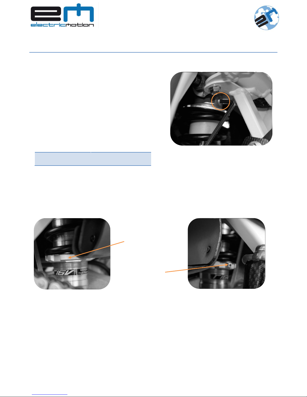
SPRING PRELOAD SETTING
Rear suspension becomes accessible to lifting the rubber wheel arch, behind the rear wheel.
The preload setting can be modified screwing and unscrewing the grooved nut.
This grooved nut is camp with the clamping nut.
Factory setting: The length of the spring is 122mm.
HARD
MIDDLE
SUPPLE
Number
of notchs
0 – 7
7 – 14
14 - 20
Figure 2 : Réglage hydraulique amortisseur
The setting is accessible from the right of the
motorcycle on the top of the suspension with
Allen key 4 mm.
20 notches exist to adjust the hydraulic system.
Grooved nut
Clamping
screw
Figure 4 : Spring preload Setting
Figure 3 : Clamping screw
Figure 1 : Hydraulic setting

8
EM-TL01-J OWNER’S MANUAL 2014
4. FORKS EMSport
Tableau 2 : hydraulic setting
The calibration of the spring can be modified with Allen key 6 mm.
11 turns exist to adjust the calibration of the spring.
Factory setting: 6 turns.
FORKS OIL CHANGE
Oil change intervals recommended are the following:
After the 50 first hours
Every 6 months
V If the intervals of oil change are not respected, the specifications of the fork could be deteriorated. Moreover
the thickening of oil itself which can lead to oil leaks from the seal.
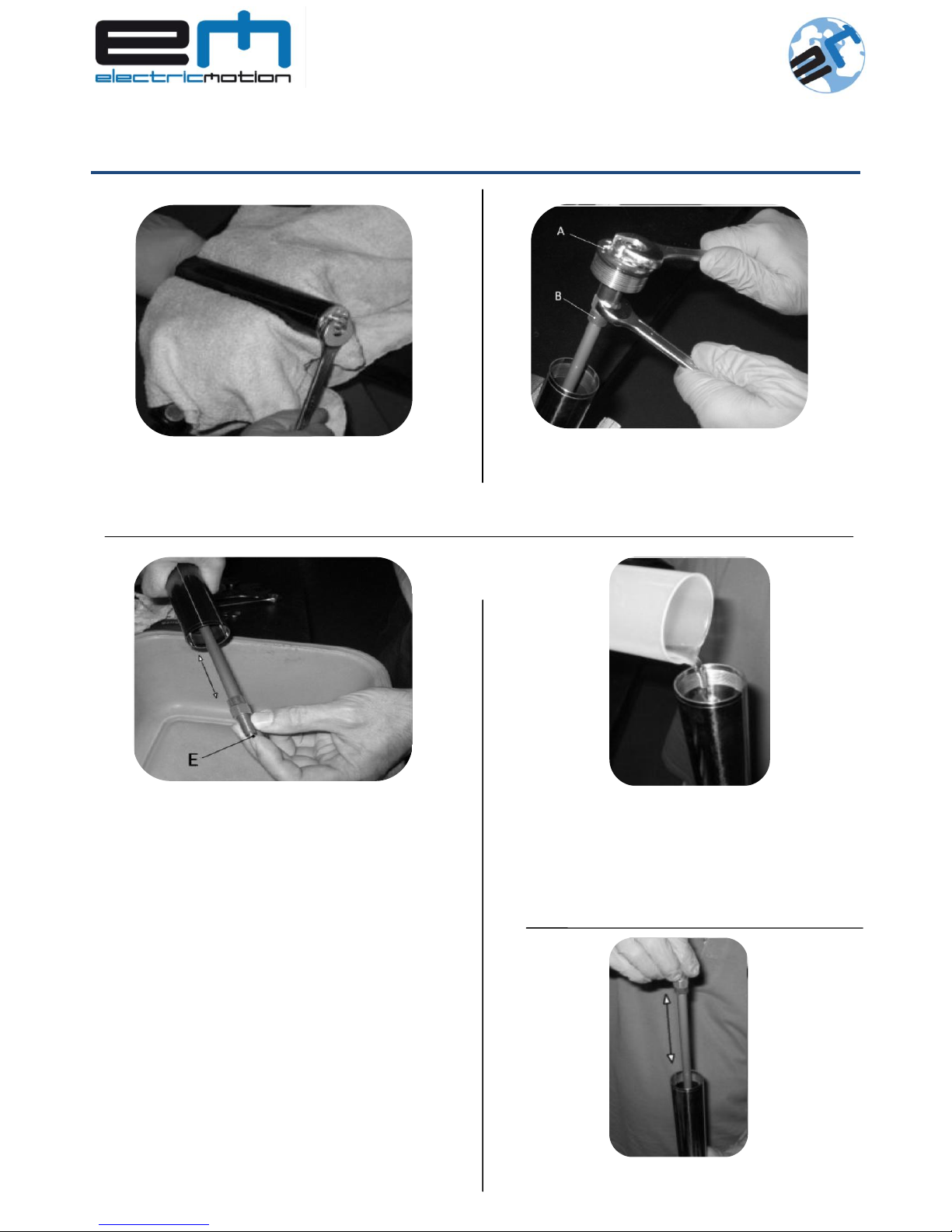
To change oil of the fork:
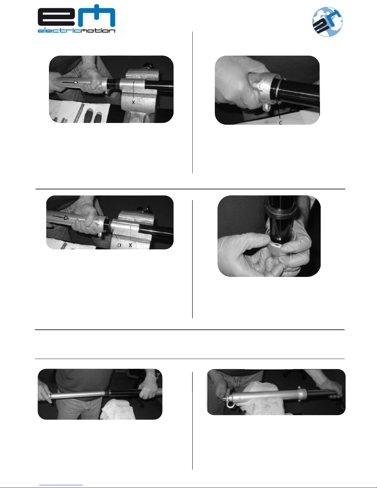
- Clean the fork;
- Protect the surface of the inner tubes and clamp it in vise, as you can see in the following picture.
V Tighten the vise moderately in order not distorted the inner tube.
HARD
MIDDLE
SUPPLE
Number of
notches
0 – 11
11 – 22
22 - 33
Figure 5 : Setting of calibration of the spring
HARD
MIDDLE
SUPPLE
Number of
notches
0 – 4
4 – 7
7-11
Figure 6 : Réglage fourche
Hydraulic setting
Calibration of the
spring
The fork is composed of:
- Fork leg with spring;
- Fork leg with hydraulic system.
The hydraulic setting can be modified on the top of the
fork with a plate screwdriver.
33 notches exist to adjust hydraulic.
It is better to start to close the hydraulic screwing the
screw to the stop and to unscrew to the required position.
Factory setting: 16 notches.
9
EM-TL01-J OWNER’S MANUAL 2014
OIL CHANGEMENT OF HYDRAULIC FORK (RIGHT)
Unscrew entirely the cap to the fork
with key 17 mm.
Remove the cap « A » in order to access
the nut « B ».
Unscrew with key 14 mm the nut « B », holding
the cap “A”
Keep in position the nut « B » with the stem
« E » to avoid the spilling of it.
Flow the oil in container. To flow all the oil pump
with the stem “E”.
V Collect the oil to bring in a recycling center to
reduce the environmental impact.
Position the fork in vertical position
and pour 280 mL of new oil.
Oil type: OJ 01 (SAE 5)
Use the stem to pump, to fill the fork.
10
EM-TL01-J OWNER’S MANUAL 2014
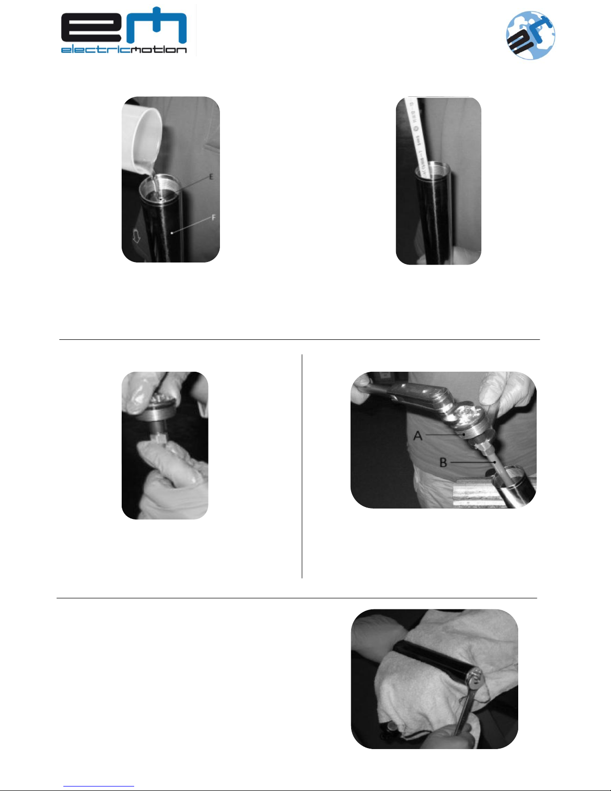
❻ Complete the topping out of oil: Bring the oil level suitable 55 mm from the top edge of the tube
❼ Screw entirely the cap to the stem
« E ».
Hold the cap « A » and screw the nut
« B » with a tightening torque of 14.7Nm.
With key 17 mm, screw the cap in the
fork tube with a tightening torque between
11.7 and 13.7 Nm.

11
EM-TL01-J OWNER’S MANUAL 2014
OIL SEAL CHANGE RIGHT SIDE
Proceed as follows:
Remove of the motorcycle and clean the suspension;
Protect the surface of the inn as shown in figure.
V Tighten the vice moderately in order not to ovalize the inner tube.
Follow the steps ❶, ❷ and ❸ of oil change of the right fork.
❶ Insert a tube into the hole for the
wheel and unscrew the cartridge with a 12
mm a socket wrench.
❷ Remove the locking screw pump with
sealing washer oil.
❸ Remove the cartridge from the inner
tube.
❹ Turn the fork and remove the hydraulic
cone limit.
12
EM-TL01-J OWNER’S MANUAL 2014
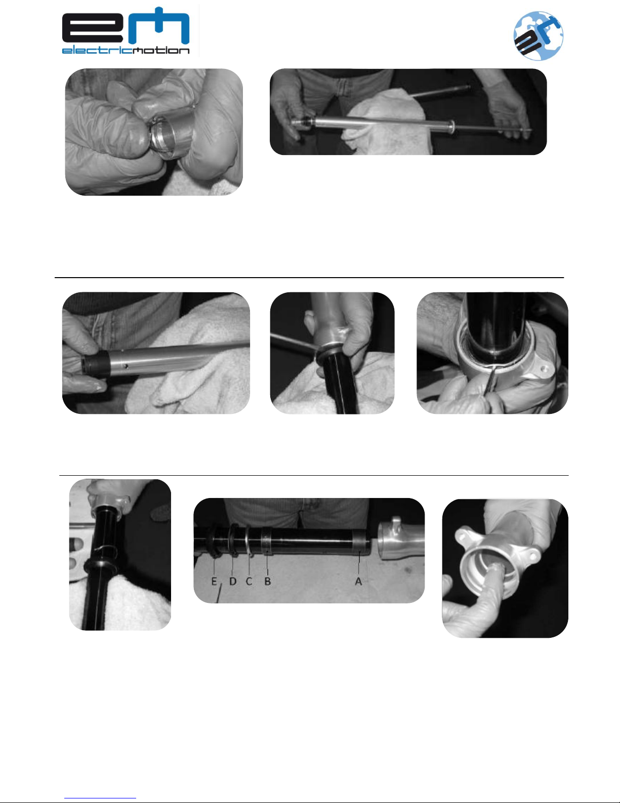
❺ Push in the compression group and
remove the snap ring from its seat.
❻ Remove the compression unit:
- Place the cartridge on a basin for collecting oil and slide the rod
into the tube of the cartridge until complete discharge of oil.
- Replace the hydraulic unit in the cartridge.
- Replace the snap ring in its housing (see figure), making sure
they fit well.
❼ Insert the cone end of stroke in the
bottom cartridge.
❾ Remove the snap ring from
its seat.
❿ Tighten the upper
part of protecting hose
clamp (see figure),
exercising the decisive
blows on the leg.
Remove oil seal and
bushing from the outer
tube itself.
⓫ Remove the tube all the
above parties (A-B-C-D-E).
Replace the “A” with a new
one.
⓬ Grease the base in
the bushing and seal the
outer tube.
❽ Pry up the edge of the
scraper and remove it from
the seat of the leg.
13
EM-TL01-J OWNER’S MANUAL 2014
⓭ Tighten the pipe in the vise with the
special shells "X" side without checking that
the drain is against bush "B".
·With decisive blows of the outer tube, the
bushing “B” in place N.B.: check that it is
fully entered into here.
⓮ Insert the nut "C" against bushing "B",
making sure that the lip of the collar is
upwards.
⓯ Insert the oil seal in the tube (with the
spring upward view) and close the hose
clamp with the shells “X” with the drain to
the oil seal.
·With moderate shots of the leg, insert the
oil seal in the “D”.
N.B.: This does not need a lot of strength.
Avoid hitting the seal once it is in place.
⓰ Insert the snap ring in place
⓱ Follow “maintenance of dust seal” instructions step 4 to 6, to assembly the dust seal in the manual
⓲ Insert the cartridge into the tube up to
send her home in the bottom of the leg.
⓳ With holding cartridge rod on the bottom
of the leg, send the parcel cartridge life.
14
EM-TL01-J OWNER’S MANUAL 2014
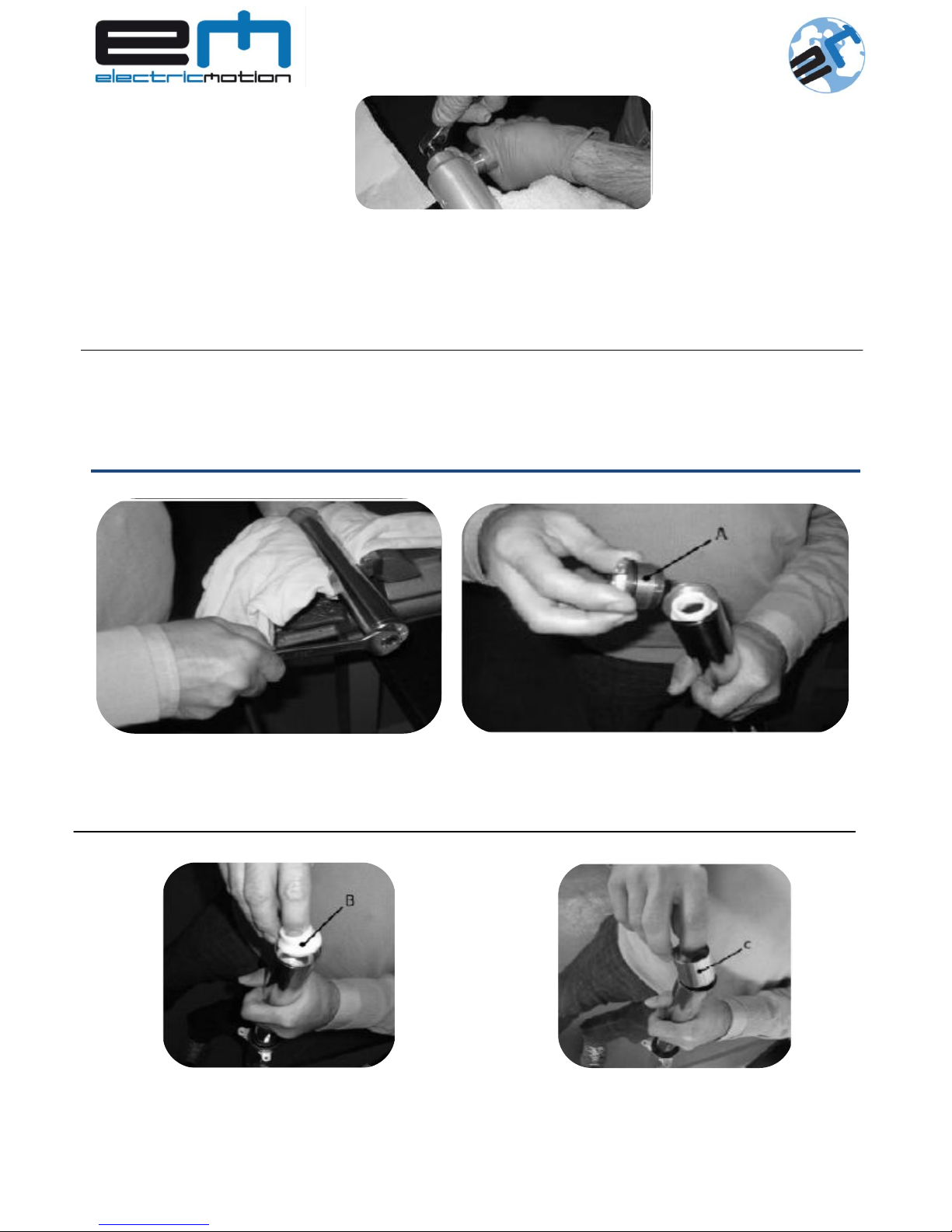
OIL CHANGEMENT OF SPRING FORK (LEFT)
Unscrew entirely the cap « A » to the
fork tube with key 17 mm.
Remove the cap « A », and put it in clean
place.
Remove the following elements:
Pull the conical spacer « B » and put in a clean place.
Pull the spacer « C » and put in a clean place.
⓴ Moderately tighten the leg in the vice
for not ovalize that, protecting it with a
clotch.
Insert a tube into the hole axle and tighten
with the torque of 23.5 – 25.5 Nm.
To finish the maintenance, follow “Oil changement of hydraulic fork (right)” above in the manual
instructions, step ❻ to ❾, to fill oil, and reassembly the fork.
15
EM-TL01-J OWNER’S MANUAL 2014
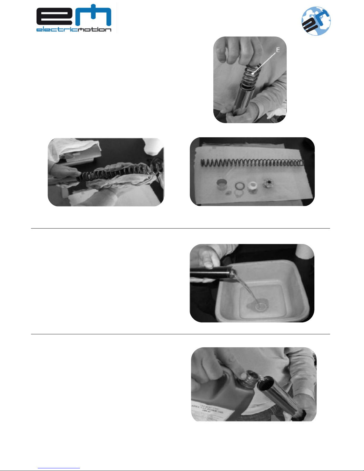
Pull slowly spring « E » and at the same time dry it
with a cloth.
Put all the elements in a clean place.
Pour the oil in a container.
V Collect the oil to bring in a recycling
center to reduce the environmental impact.
Place the suspension in a vertical position,
and put some oil.
Oil type : OJ 01 (SAE 5)
 Loading...