

Electric Mobility EM 140T, EM 140F Owner's Manual
EM 140T / 140F
Owner’s Manual
ELECTRIC
MOBILITY
1 Mobility Plaza
Sewell, NJ 08080

Model 140T/140F Owner’s Manual
ELECTRIC
MOBILITY
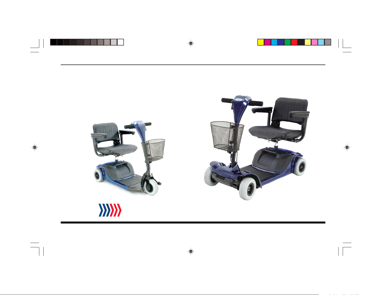
Thank you for purchasing the Model 140T/140F. With proper care, this vehicle should give you a lifetime of fun
and excitement. You will enjoy the freedom to do what you want, when you want, and when you want to.
Your satisfaction means everything to us. That’s why we have the best customer service in the industry.
Information on our service and warranties are all spelled out in a subsequent section of this manual.
Electric Mobility’s mission is to provide easy to use, convenient and portable mobility products to help you get
more out of your life.
Please call us at 1-800-257-7955 if you have any questions.
EMC Part: 44000700 • Rev. 02 • 04/19/06
i

ELECTRIC
MOBILITY
Model 140T/140F Owner’s Manual
Contents
Title Page
Safety Information.......................................................................................................................................................................................... 1
Important Information Regarding Electromagnetic Interference (EMI) .........................................................................................3
Getting to know your Model 140T/140F .............................................................................................................................................6
Components.................................................................................................................................................................................................. 6
Figure 1 — Model 140F Components ................................................................................................................................................6
Initial Setup .................................................................................................................................................................................................... 7
Installing Seat and Front Basket ....................................................................................................................................................... 7
Seat Installation ............................................................................................................................................................................8
Figure 2 — Seat Installation ................................................................................................................................................ 8
Front Basket Installation ....................................................................................................................................................................8
Charging Battery .................................................................................................................................................................................. 9
Figure 3 — Battery Charging, Off Vehicle ................................................................................................................................... 9
Figure 4 — Battery Case Charging Connection .......................................................................................................................10
Controls and Adjustments....................................................................................................................................................................... 11
Operating Controls...........................................................................................................................................................................11
Dash Controls ............................................................................................................................................................................ 11
Figure 5 — Dash Controls..................................................................................................................................................11
Speed Dial .................................................................................................................................................................... 11
LED Status Indicator............................................................................................................................................... 12
Battery Meter ............................................................................................................................................................. 12
Horn ..............................................................................................................................................................................12
EMC Part: 44000700 • Rev. 02 • 04/19/06
ii

Model 140T/140F Owner’s Manual
ELECTRIC
MOBILITY
On/Off Key ..................................................................................................................................................................12
Figure 6 - Key Location ..................................................................................................................................... 12
Forward/Reverse Engager Levers...........................................................................................................................13
Adjusting Armrests ............................................................................................................................................................................13
Figure 7 — Armrest Adjustment.................................................................................................................................................13
Adjusting Seat ................................................................................................................................................................................ 14
Figure 8 - Seatpost Height Adjustment ..................................................................................................................................14
Adjusting Handlebar Assembly .......................................................................................................................................................16
Figure 9 — Handlebar Assembly Adjustment...........................................................................................................................16
Handlebar Assembly Lock ...............................................................................................................................................................17
Figure 10 — Handlebar Assembly Lock ...................................................................................................................................17
Accessories..................................................................................................................................................................................................17
Using the 140T/140F....................................................................................................................................................................................18
Day-to-Day Use .......................................................................................................................................................................................... 18
Transferring On or Off the Vehicle................................................................................................................................................ 19
Driving ..................................................................................................................................................................................................20
Speed Settings ............................................................................................................................................................................20
Inclines..........................................................................................................................................................................................21
Cornering & Turning .................................................................................................................................................................21
Curbs and Small Obstacles .....................................................................................................................................................21
Brake Release Lever..................................................................................................................................................................22
Figure 11 — Brake Release Lever and Overload Fuse ...................................................................................................22
Overload Fuse ............................................................................................................................................................................23
Disassembly & Re-Assembly ...................................................................................................................................................................24
Figure 12 - Model 140F Disassembled ........................................................................................................................................................... 24
EMC Part: 44000700 • Rev. 02 • 04/19/06
iii

ELECTRIC
MOBILITY
Model 140T/140F Owner’s Manual
Disassembling Your Model 140T/140F ..........................................................................................................................................25
Figure 13 - Battery Case Removal ........................................................................................................................................................... 25
Figure 14 - Frame Buckle ........................................................................................................................................................................... 25
Figure 15 - Disconnect Rear Drivetrain Assembly ............................................................................................................................... 26
Figure 16 - Front Frame Assembly Detachment ................................................................................................................................... 26
Re-assembling the Model 140T/140F ...........................................................................................................................................27
Figure 17 - Aligning Front Frame Assembly to Rear Drivetrain Assembly ...................................................................................... 27
Transporting Model 140T/140F.............................................................................................................................................................. 29
Maintenance and Servicing ......................................................................................................................................................................31
Preventative Maintenance ........................................................................................................................................................................32
Seat Upholstery.................................................................................................................................................................................. 32
Bodywork ............................................................................................................................................................................................32
Storage .................................................................................................................................................................................................33
Electronics ...........................................................................................................................................................................................33
Motor Brakes...................................................................................................................................................................................... 33
Driving Brake ......................................................................................................................................................................................33
Tires ......................................................................................................................................................................................................33
Battery ...............................................................................................................................................................................................34
Troubleshooting Guide .............................................................................................................................................................................35
Controller Fault Codes ............................................................................................................................................................................37
Parts Ordering/Factory Return Procedures .......................................................................................................................................38
Specifications...................................................................................................................................................................................................39
Limited Warranty ..........................................................................................................................................................................................40
EMC Part: 44000700 • Rev. 02 • 04/19/06
iv

Model 140T/140F Owner’s Manual
ELECTRIC
MOBILITY
Figures
Figure Number Title Page
1 Model 140F Components ................................................................................................................................. 6
2 Seat Installation ................................................................................................................................................... 8
3 Battery Charging, Off Vehicle ...........................................................................................................................9
4 Battery Case Charging Connection .............................................................................................................10
5 Dash Controls ...................................................................................................................................................11
6Key Location ......................................................................................................................................................12
7 Armrest Adjustments.......................................................................................................................................13
8 Seatpost Height Adjustment...........................................................................................................................14
9 Handlebar Assembly Adjustment ..................................................................................................................16
10 Handlebar Assembly Lock...............................................................................................................................17
11 Brake Release Lever and Overload Fuse ....................................................................................................22
12 Model 140F Disassembled ............................................................................................................................ 24
13 Battery Case Removal .....................................................................................................................................25
14 Frame Buckle Unfastened ...............................................................................................................................25
15 Rear Drivetrain Assembly Disconnected ....................................................................................................26
16 Front Frame Assembly Detachment ............................................................................................................. 26
17 Aligning Front Frame Assembly to Rear Drivetrain Assembly ...............................................................27
No liability is assumed with respect to the use of any information contained in this publication. While every precaution has been taken in the preparation of this
publication, Electric Mobilty Corp., assumes no responsibility for errors or omissions nor is any liability assumed for damages resulting from the use of information
contained in this publication. This publication, as well as operational details described herein, are subject to change without notice.
EMC Part: 44000700 • Rev. 02 • 04/19/06
v

Model 140T/140F Owner’s Manual
ELECTRIC
MOBILITY
Safety Information
Read and understand these Warnings and the entire manual before using your Model 140T/140F Scooter. Failure to follow
these instructions may result in damage to the vehicle or serious injury. NOTE: The caster wheels may NOT
prevent the scooter from tipping if scooter is used improperly.
WARNING!
This vehicle is not a medical device and is NOT intended for use by those with mobility problems or
medical disabilities.
1. DO NOT exceed the specifications of this unit, modify
this unit in anyway, or use the unit for a purpose other
than as intended.
2. DO NOT operate this unit if your health or
medications you are taking cause you to feel dizzy, affect
your vision, or in any way impact your thought process,
coordination, or ability to safely operate the unit.
Check with your physician should you experience any of
these symptoms.
3. DO NOT operate this unit after consuming any
alcoholic beverages.
EMC Part: 44000700 • Rev.02 • 04/19/06
1
4. DO NOT transfer “on” or “off” the unit until it is
turned “OFF”, completely stopped, and when it is on a
stable and level surface.
5. DO NOT attempt to ride over curbs or other
obstruction higher than 2 inches.
6. DO NOT stop when going up an incline. If you must
do so, always lean forward to shift the center of gravity
and prevent the unit from tipping.
7. DO NOT climb inclines that pose a concern for
stability.

ELECTRIC
MOBILITY
Model 140T/140F Owner’s Manual
8. DO NOT drive across an incline or attempt to turn
while on an incline.
9. DO NOT back down an incline or allow the unit to be
backed down an incline.
10. DO NOT turn off the power while the unit is moving.
11. ALWAYS remember vehicle capacity is limited to one
person only. This unit is not approved for towing or for
weights in excess of the published maximum.
12. ALWAYS drive straight up and down inclines.
13. ALWAYS turn the power off when the unit is not in
use. This will not only extend the life of the charge in
the battery but will keep the unit from being
accidentally moved.
14. ALWAYS use a grounded receptacle. Use of a non-
grounded receptacle could result in an electrical shock.
15. ALWAYS reduce speed when making a turn.
16. ALWAYS keep arms and legs within the confines of
the unit.
17. USE EXTRA CAUTION when climbing inclines
(ramps, hills, driveways, etc.).
18. USE CAUTION when braking on an incline or wet or
slippery surfaces as the unit will take longer to come to
a complete stop.
19. USE CAUTION when operating the unit in bad
weather or driving through water as moisture could
affect the control system or other parts of the unit
either temporarily or permanently.
20. OPERATOR must remain seated when the unit is
moving.
21. NEVER hose off your vehicle or allow it to come in
direct contact with water.
22. NEVER use your unit in a shower or steam room.
23. NEVER charge batteries that may be frozen.
EMC Part: 44000700 • Rev.02 • 04/19/06
2

Model 140T/140F Owner’s Manual
ELECTRIC
MOBILITY
Important Information Regarding Electromagnetic Interference (EMI)
It is very important that you read this information regarding the possible effects of electromagnetic interference (EMI) on
your scooter.
Electromagnetic interference (EMI) refers to the effects that outside sources of electromagnetic energy (radio and
television broadcasts, CB radios, garage door openers, cellular telephones, etc.) might have on the control systems of your
scooter. The interference from these sources could cause the scooter to release its brakes, move by itself, or to move in
an unintended direction. EMI could also result in permanent damage to the control system.
The sources of electromagnetic energy can be broadly classified into three types:
• Hand held short-range portable transceivers — These are transmitter/receivers with the antenna mounted
directly on the unit. Examples include: citizen band (CB) radios, “walkie-talkies”, security, fire and police transceivers,
cellular telephones, and devices that transmit signals even when not in use.
• Medium range mobile transceivers — These usually have the antenna mounted outside of a vehicle or building.
Examples include: police, fire, ambulance and taxi transceivers.
• Long range transmitters and receivers — These usually have the antenna mounted on a tower. Examples
include: commercial radio/television broadcasts and amateur (HAM) radios.
EMC Part: 44000700 • Rev.02 • 04/19/06
3

ELECTRIC
MOBILITY
Model 140T/140F Owner’s Manual
Other types of hand-held devices like cordless phones, laptop computers, AM/FM radios, and small appliances like hair
dryers or electric shavers may also generate electromagnetic energy, but it is such a small amount that, as far as we know,
no EMI problems should occur with these devices.
The intensity of interference from electromagnetic energy is measured in volts per meter (v/m), which refers to the
strength of the electrical source (voltage) as it relates to the distance away from the object being considered (in meters).
Resistance of a scooter to a certain EMI intensity is commonly called its “immunity level.” A level of 20 volts/meter is a
generally achievable and useful immunity level against interference from radio wave sources (the higher the immunity level,
the greater the protection).
Your scooter has been tested and found to meet the required immunity level for Electromagnetic Interference (20 v/m).
EMC Part: 44000700 • Rev.02 • 04/19/06
4

Model 140T/140F Owner’s Manual
ELECTRIC
MOBILITY
WARNING!
Even with an immunity level of 20 volt/meter, certain precautions must be followed
to ensure that your vehicle will not be affected by outside electromagnetic sources.
•Do not operate hand-held transceivers such as citizen band (CB) radios or turn on powered communication
devices such as cellular phones while the scooter is turned on.
• Be aware of nearby transmitters, such as radio and television stations, and avoid coming close to them.
• If an unintended movement should occur while operating the scooter, turn the power “off” as soon as it is safe to
do so.
• Be aware that if you do operate any electrically powered accessories, radios, cellular phones, or other devices, that
your scooter may become more susceptible to interference from outside electromagnetic sources.
• Report all incidents of unintended movement or unexpected brake releases to Electric Mobility’s customer service
department.
EMC Part: 44000700 • Rev.02 • 04/19/06
5
ELECTRIC
MOBILITY
Model 140T/140F Owner’s Manual
Getting to know your Model 140T/140F
Your Model140T/140F scooter from Electric Mobility is a powerful, useful vehicle that offers increased mobility with easy,
safe operation. Before using your 140T/140F, use this section to first familiarize yourself with the components, setup,
controls, and adjustments to enjoy it safely and successfully.
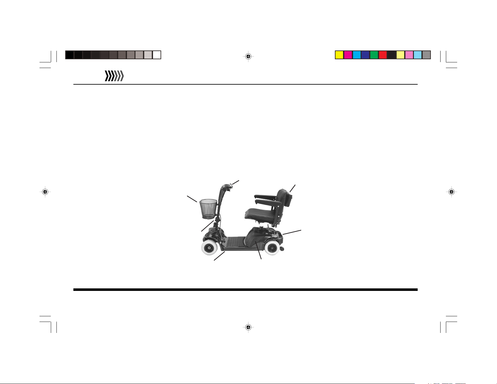
Components
The Model 140T/140F consists of the following major components. Locations are shown in Figure 1.
FRONT
BASKET
HANDLEBAR
ASSEMBLY
DASH AND CONTROLS
SEAT
REAR DRIVETRAIN
ASSEMBLY
FRONT FRAME
ASSEMBLY
Figure 1 — Model 140F Components
EMC Part: 44000700 • Rev.02 • 04/19/06
6
REMOVABLE
BATTERY CASE

Model 140T/140F Owner’s Manual
ELECTRIC
MOBILITY
Initial Setup
Prior to using your Model 140T/140F, use the following to initially setup the vehicle for proper use and safe, comfortable
operation. Initial setup involves installing the seat and front basket. If the vehicle is delivered with the seat and basket
installed, you can skip this section and proceed with how to charge the battery before riding.
Installing Seat and Front Basket
The 140T/140F includes a swivel seat and detachable front basket that may require installation when you first receive it.
EMC Part: 44000700 • Rev.02 • 04/19/06
7
ELECTRIC
MOBILITY
Model 140T/140F Owner’s Manual
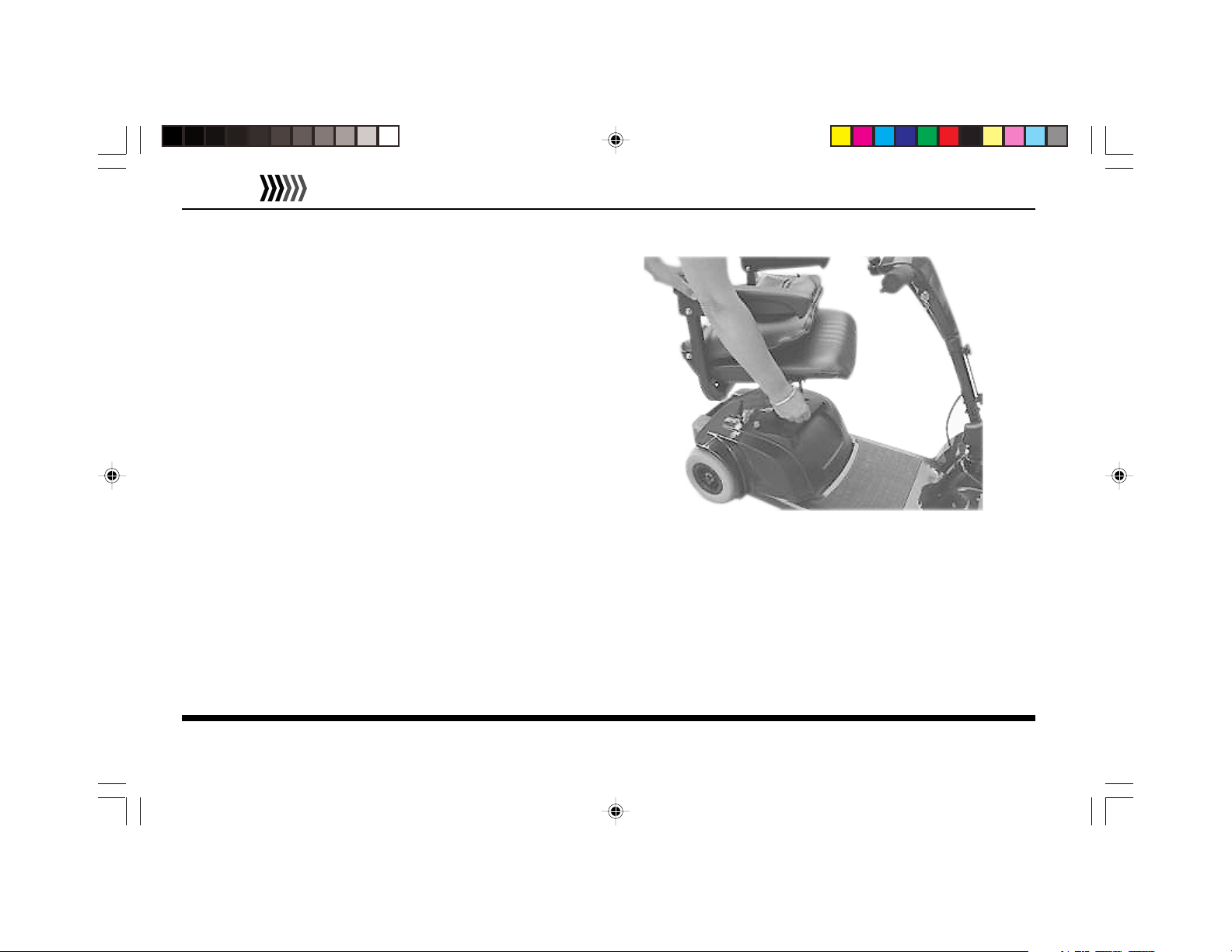
Seat Installation
To install the seat begin by pulling the locking lever back,
located beneath the seat. Insert the seat onto the seat post
tube, and release the locking lever to lock seat in position.
Turn the seat back and forth slightly allowing the lever to
lock into position. Seat installation is shown in Figure 2.
Front Basket Installation
The front Basket installs on the basket mounting brackets
located on the scooter handlebar assembly. Align basket
with mounting brackets and push firmly down to secure
basket in position.
Figure 2 - Seat Installation
EMC Part: 44000700 • Rev.02 • 04/19/06
8
Model 140T/140F Owner’s Manual
Charging Battery
It is recommended to charge your batteries:
•
Upon initial receipt of your Model 140T/140F
• For 6-8 hours (overnight) after extended use during
the day
• Whenever the battery meter indicator goes into the
red area
• The battery’s life expectancy may be shortened if
batteries are left fully discharged for more than a day.
To Charge the Battery:
1. Locate and identify the separate Battery Charger and
AC line cord that accompanies the vehicle.
ELECTRIC
MOBILITY
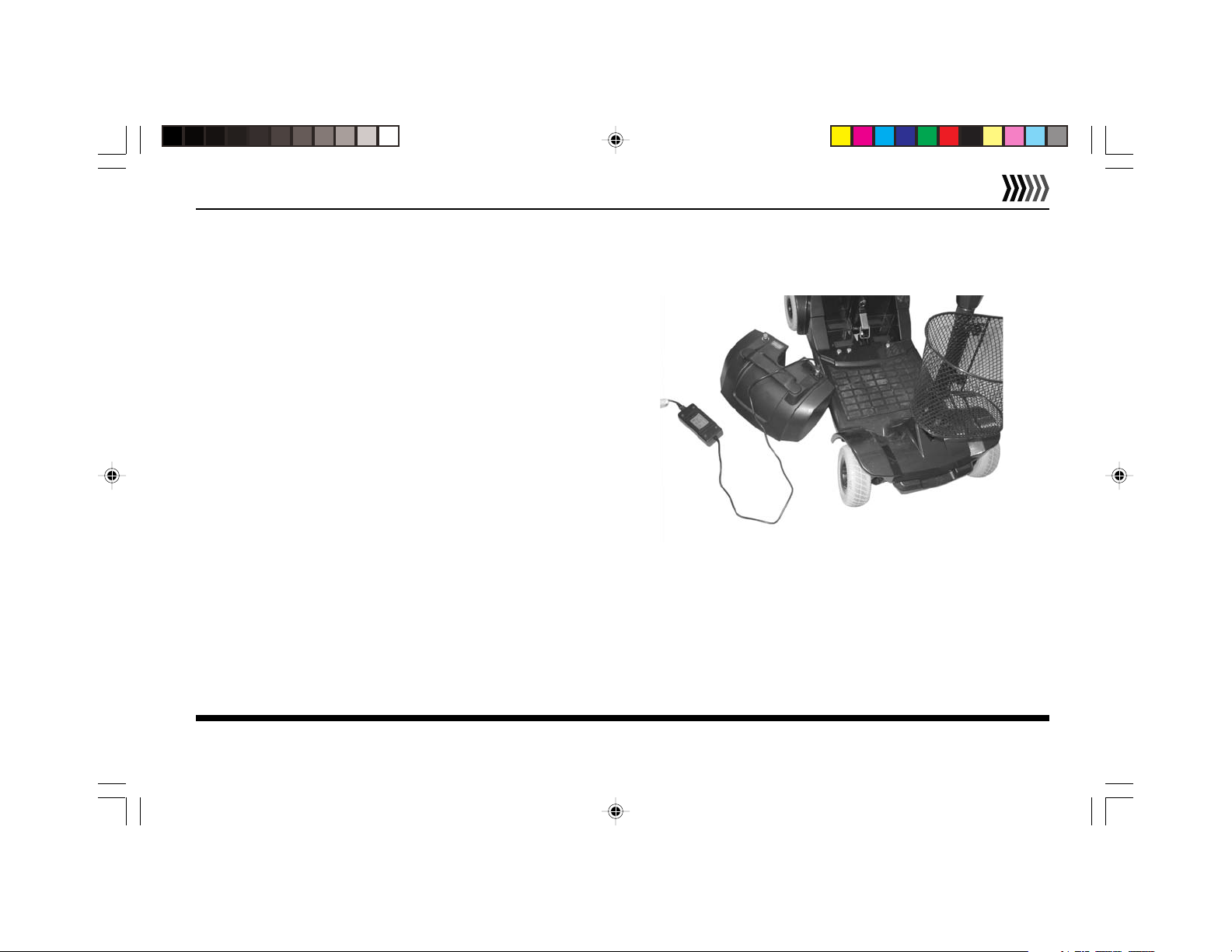
2. The Battery can be charged either on or off the vehicle.
If more convenient, detach Battery Case from vehicle
and set on dry, flat surface as shown in Figure 3.
EMC Part: 44000700 • Rev.02 • 04/19/06
9
Figure 3 - Battery Charging, Off Vehicle
 Loading...