

Page 1

FUSION-4™ LIGHTED MIRROR
INSTALLATION INSTRUCTIONS
THERE’S ONLY ONE™ ELECTRIC MIRROR®
www.electricmirror.com | | © 2013 ELECTRIC MIRROR LLC
All designs, engineering drawings, images, photographs, logos, and written
material that appear in this instruction manual is protected by copyright.
Page 2
ELECTRIC MIRROR® THE LEADER IN LIGHTED MIRROR AND MIRROR TV TECHNOLOGY
FUSION-QUAD BACKLIT
MIRROR
Installation Instructions
Made in USA
ELECTRIC MIRROR, LLC
Seattle, WA • USA
T +1 425 776–4946
F +1 425 491–8200
© 2013 ELECTRIC MIRROR®
residential@electricmirror.com
www.electricmirror.com
Page 3

ELECTRIC MIRROR® THE LEADER IN LIGHTED MIRROR AND MIRROR TV TECHNOLOGY
Important Safety Instructions
Must be installed by a qualified technician.
Made in USA
Read these installation instructions.
Keep these instructions for future use.
Follow all instructions. Install in accordance with manufacturer's instructions.
FAILURE TO FOLLOW INSTRUCTIONS COULD RESULT IN DEATH OR SERIOUS INJURY
FAILURE TO FOLLOW INSTRUCTIONS
VOIDS
WARRANTY.
This luminaire must be mounted or supported independently of an outlet box.
Make sure electrical connections are wired correctly. Power and neutral wires must
be connected to the luminaire disconnect. Insert the power wire into the black colored
insert and the neutral wire into the white colored insert.
The ground must be connected. Do not defeat the safety purpose of the grounding
wire inside the chassis. The chassis must be grounded to avoid possible electrical shock.
ELECTRIC MIRROR, LLC
Seattle, WA • USA
WARNING:
CAUTION:
T +1 425 776–4946
F +1 425 491–8200
CAUTION
READ ALL INSTRUCTIONS
PRIOR TO INSTALLATION
TO PREVENT INJURY, THE MIRROR MUST
BE INSTALLED IN ACCORDANCE WITH
THE MANUFACTURER'S INSTRUCTIONS
THE ONLY USER SERVICEABLE PARTS INSIDE
ARE THE LAMPS.
OTHER COMPONENTS MUST BE SERVICED
BY QUALIFIED ELECTRICIANS. LUMINAIRE
DISCONNECT MUST BE DISCONNECTED
PRIOR TO COMPONENT SERVICING
© 2013 ELECTRIC MIRROR®
residential@electricmirror.com
www.electricmirror.com
Page 4

ELECTRIC MIRROR® THE LEADER IN LIGHTED MIRROR AND MIRROR TV TECHNOLOGY
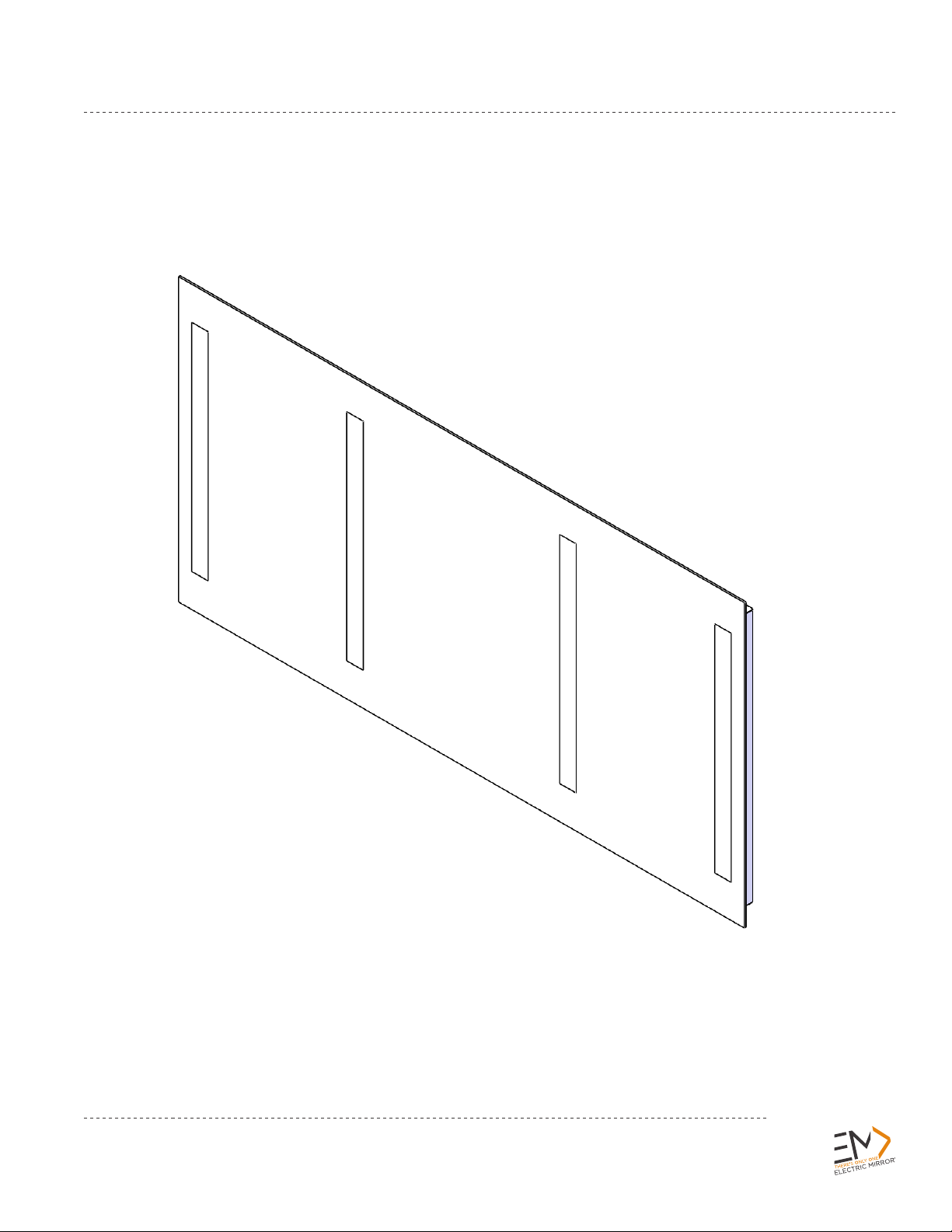
Unpacking your Lighted Mirror
Verify Contents
Prior to installation, unpack items and verify contents. The backlit mirror comes with 2
boxes:
Box 1: Chassis Assembly
Label will include part number: FUS-QUA-(size)-C
Made in USA
Box 2: Mirror Assembly With Integral Hangers
Label will include part number: FUS-QUA-(size)-M
Front View
Back View
ELECTRIC MIRROR, LLC
Seattle, WA • USA
T +1 425 776–4946
F +1 425 491–8200
© 2013 ELECTRIC MIRROR®
residential@electricmirror.com
www.electricmirror.com
Page 5

ELECTRIC MIRROR® THE LEADER IN LIGHTED MIRROR AND MIRROR TV TECHNOLOGY
Made in USA
Installation
1) Mounting chassis on the wall
Before mounting chassis on wall, identify mirror location on wall. Drill marks should be measured
from the edge of the mirror
There are multiple mounting holes that can be chosen from to accommodate mounting locations. The
chassis shall be installed with a minimum of (4) 1/4" x 1-1/2" lag screws or other engineering approved
fasteners. Use wall anchors or reinforced backing areas to support chassis. See individual product
specifications for mounting hole locations.
2) Install lamps.
3) Wiring Details
Please note, all electrical installations should be carried out by a fully qualified
electrician in conformance with the National Electrical Code and local building codes.
NOT FROM EDGE OF CHASSIS
.
Neutral (White)
Ground Push-In
Connector
Chassis Knockout
Luminaire Disconnect
Power (Black)
4) Power Connection
Before proceeding to power supply wiring, make sure the MC cable is brought in through the wall and
into the chassis knockout.
Insert ground wire in the grounded connector. Insert the power and neutral wires into the luminaire
disconnect. The power wire is inserted into the black port (number 1) and the neutral wire is
inserted into the white port (number 2).
ELECTRIC MIRROR, LLC
Seattle, WA • USA
Luminaire
Disconnect
T +1 425 776–4946
F +1 425 491–8200
© 2013 ELECTRIC MIRROR®
residential@electricmirror.com
www.electricmirror.com
Page 6

ELECTRIC MIRROR® THE LEADER IN LIGHTED MIRROR AND MIRROR TV TECHNOLOGY
Made in USA
Hanger Slot
Two Places
DETAIL
SCALE 1 : 4
Mirror
Mirror Hanger
Mirror Clip
Chassis Tab
Two Places
DETAIL
SCALE 1 : 4
Chassis flange
5) Mirror Mounting
After wiring process is completed, mirror is ready to be hung on the chassis. The weight of the mirror
is supported at the top of the chassis. The mirror clip, at the bottom of mirror, is used to keep the
mirror from moving away from the wall.
Hang mirror on chassis by aligning tabs on chassis through mirror hanger slots while holding the
mirror against the chassis. Slide the mirror down inserting the chassis tabs into the hanger slots.
Make sure both tabs are engaged through hanger slots and the mirror clip rests in the chassis
flange.
© 2013 ELECTRIC MIRROR®
ELECTRIC MIRROR, LLC
Seattle, WA • USA
T +1 425 776–4946
F +1 425 491–8200
residential@electricmirror.com
www.electricmirror.com
 Loading...