


EFINITY™
LIGHTED MIRROR
Installation Instructions
IMPORTANT SAFTEY INSTRUCTIONS
Must be installed by a qualified technician.
Read these installation instructions. Keep these instructions for future use.
Follow all instructions. Install in accordance with manufacturer's instructions.
FAILURE TO FOLLOW INSTRUCTIONS COULD RESULT IN DEATH OR SERIOUS INJURY.
FAILURE TO FOLLOW INSTRUCTIONS VOIDS WARRANTY.
This luminaire must be mounted or supported independently of an outlet box.
Make sure electrical connections are wired correctly. Power and neutral wires must
be connected to the luminaire disconnect. Insert the power wire into the black colored
insert and the neutral wire into the white colored insert.
The ground must be connected. Do not defeat the safety purpose of the grounding wire inside the chassis.
The chassis must be grounded to avoid possible electrical shock.
CAUTION
READ ALL INSTRUCTIONS PRIOR TO INSTALLATION
WARNING:
TO PREVENT INJURY, THE MIRROR MUST BE INSTALLED IN ACCORDANCE WITH THE MANUFACTURER’S
INSTRUCTIONS
CAUTION: THE ONLY USER SERVICEABLE PARTS INSIDE ARE THE LAMPS.
OTHER COMPONENTS MUST BE SERVICED BY QUALIFIED ELECTRICIANS. LUMINAIRE DISCONNECT MUST BE
DISCONNECTED PRIOR TO COMPONENT SERVICING
UNPACKING YOUR LIGHTED MIRROR
Verify Contents
Prior to installation, unpack items and verify contents. The lighted mirror comes with 2 boxes and lamps:
BOX 1: CHASSIS ASSEMBLY
Label will include part number: EFI-(size)-C
BOX 2: MIRROR ASSEMBLY WITH INTEGRAL HANGERS
Label will include part number: EFI-(size)-M
2 THERE’S ONLY ONE™ ELECTRIC MIRROR® | E sales@electricmirror.com | T +1 425 776-4946 | F +1 425-491-8200 | W www.electricmirror.com

INSTALLATION
1. MOUNT THE CHASSIS ON THE WALL
Prior to mounting the chassis on the wall, identify mirror location on wall. Drill marks should be measured from
the edge of mirror. NOT FROM EDGE OF CHASSIS There are multiple mounting holes that can be chosen to
accommodate mounting locations. The chassis shall be installed with a minimum of (4) 1/4x1 1/2” lag screws
or other engineering approved fasteners. Use wall anchors or reinforced backing areas to support chassis. See
individual product specification for mounting hole locations.
2. INSTALL LAMPS
Lamps should fit within the lamp holders provided in chassis. Rotate lamps to lock into place.
3. WIRING DETAILS
Please note, all electrical installations should be carried out by a fully qualified electrician in conformance with the
National Electrical Code and local building codes.
4. LIGHT COVER
Before proceeding to power supply wiring, make sure the MC cable is brought in through the wall and
into the chassis knockout. Insert ground wire in the grounded connector. Insert the hot and neutral wires into the
luminaire disconnect. The hot wire is inserted into the black port (number 1) and the neutral wire is inserted into the
white port (number 2).
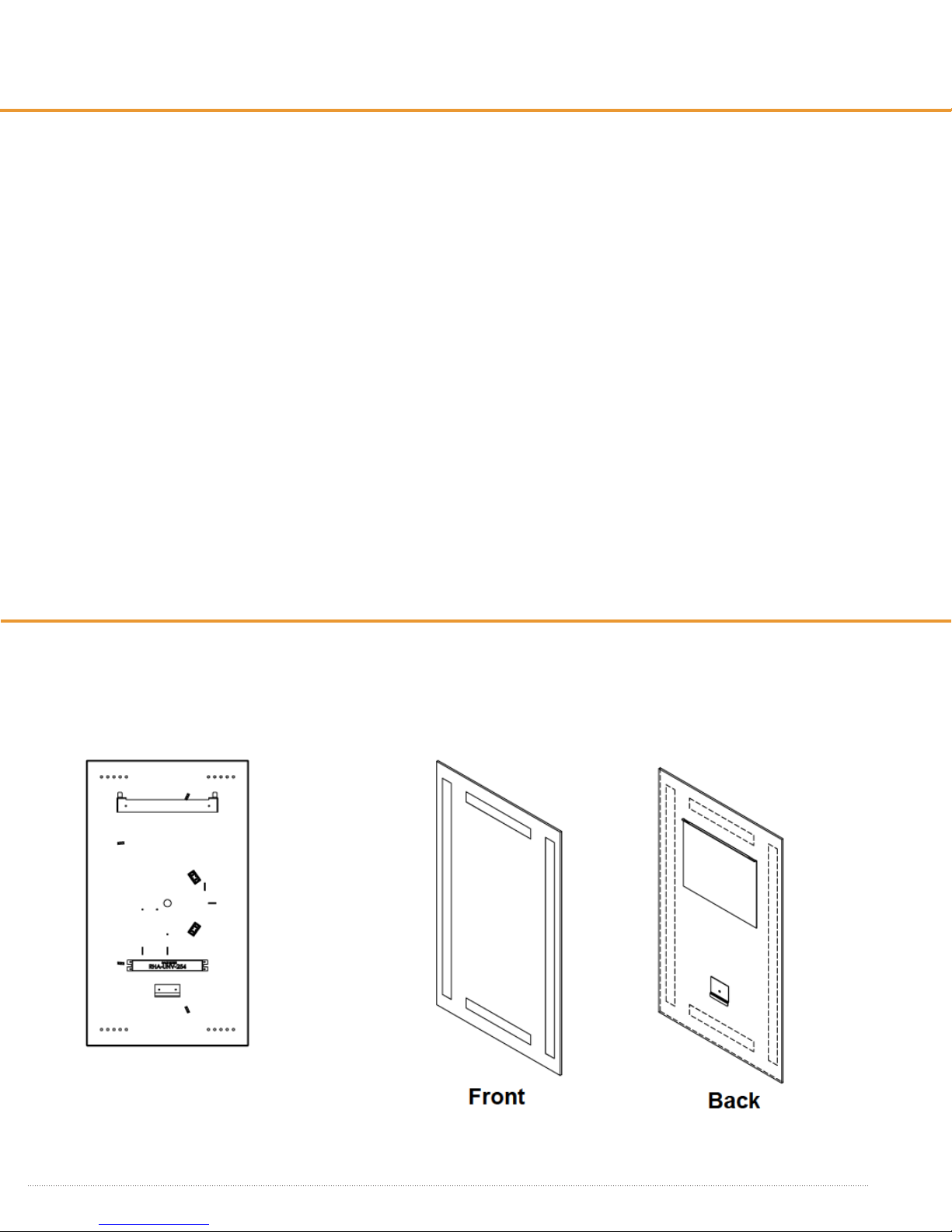
5. MIRROR MOUNTING
After wiring process is completed, mirror is ready
to be hung on the chassis. The weight of the
mirror is supported at the top of the chassis. The
mirror clip, at the bottom of mirror, is used to keep
the mirror from moving away from the wall.
Hang mirror on chassis by aligning tabs on chassis
through mirror hanger slots while holding the
mirror against the chassis. Slide the mirror down
while inserting the chassis tabs into the hanger
slots. Make sure both tabs are engaged through
hanger slots and the miror clip overlaps the
hanging bracket.
THERE’S ONLY ONE™ ELECTRIC MIRROR® | E sales@electricmirror.com | T +1 425 776-4946 | F +1 425-491-8200 | W www.electricmirror.com
3
 Loading...