

Electric Heating Company FUSION 24 kW, FUSION 14.4kW, FUSION 12kW, FUSION 9kW, FUSION 6kW Installation And Technical Manual

The COMET Range of Boilers
the ultimate solution for central heating
INSTALLATION
&
TECHNICAL MANUAL
If you require any further assistance:
Telephone: 01698 820533
Fax: 01698 825697
E-mail: info@electric-heatingcompany.co.uk
or visit our website www.electric-heatingcompany.co.uk

3
GB-031C/f.347
INTRODUCTION
Please read and follow the installation and operating instructions
carefully, to ensure the long life and reliable operation of this
appliance.
The Electric Heating Company may make minor changes
if necessary in the appliance that will not be shown in the
operating instructions, so long as the main features of the boiler
remain the same.
All boilers come with a 24 month warranty that covers all
defects originating from faulty materials and workmanship in the
manufacture of the boilers.
The warranty covers the replacement of any faulty parts and
labour costs.
The warranty will not cover any damage to the boiler from poor
or incorrect installation work.
The warranty will not cover any call out charges that have not
been organised by the Electric Heating Company Ltd.
The warranty will not cover water leaks into the boiler. All
plumbing joints must be checked.
The warranty card must be completed and sent back to The
Electric Heating Company as soon as possible for registration.
An internal Magnetic Filter is fitted to the Boiler and it must be
cleaned at least annually. (Note: Failure to clean the Magnetic
Filter may result in boiler shutdown). Warranty calls will not be
covered for this repair.
This appliance is not intended for use by persons (including children) with reduced physical, sensory or mental cap-
abilities, or lack of experience and knowledge, unless they have been given supervision or instruction concerning use
of the appliance by a person responsible for their safety.
Children should be supervised to ensure that they do not play with the appliance.
Page Contents
INTRODUCTION 3
PREPARATION 4
INSTALLATION 5
ELECTRICAL CONNECTIONS AND CONTROLS 9
EXTERNAL CONTROL WIRING 11
CONTROL PANEL CONNECTIONS 12
EXTERNAL BOILER WIRING 13
BOILER DIMENSIONS 13
USER INSTRUCTIONS 15
FAULT FINDING 16
TECHNICAL SPECIFICATIONS 17
4
GB-031C/f.347
PREPARATION
Instructions and Building Regulations
This appliance must be fitted in accordance with the following
instructions.
The Local Building Regulations
The Building Regulations
The Building Standards, (Scotland-consolidated) Regulations.
Local water bylaws. British Standards- code
of practice
BS EN 12828:2003
Heating systems in buildings. Design for water-based heating systems.
BS EN 12831:2003
Heating systems in buildings. Method for calculation of the design heat load
BS EN 14336:2004
Heating systems in buildings. Installation and commissioning of
water based heating systems
BS 7671:2008
Requirements for electrical installations. IEE Wiring Regulations.
Seventeenth edition.
BS EN 13831:2007
Closed expansion vessels with built-in diaphragm for installation
in water
C.O.S.H.H.
Materials used in the manufacture of this appliance are non-hazardous and no special precautions are required when fitting or
servicing this appliance.
PREPARATION
1. Load Check
A load check should be taken into consideration when installing
high output boilers.
2. Boiler location
The boiler must be fitted on a wall that will provide an adequate
fixing, and should be fitted in a location that the boiler and pipework are not subject to frost and damp conditions.
3. Central heating (design & installation)
Detailed recommendations are given in BS EN 12828:2003, BS
6700: 2006+A1: 2009 and CP 342-2:1974
Pipes forming part of the useful heating surface should be
insulated to prevent any potential heat loss or frost damage (BS
6700:1997).
Drain valves should be fitted at the lowest point of the system
pipe work in an accessible position.
Drain valves should be in accordance with BS 2879: 1980 and
copper tube to BS EN 1057: 1996. is recommended.
LOCATION
The boiler can be installed in almost any location within a domestic or commercial property, however consideration should be
given to future maintenance. Never leave the boiler switched off
if there is danger of having temperatures below 0°C in the room
where it is located.
We recommend that a minimum clearance of 450 mm should be
allocated for the removal of the front cover and adequate access
to the boiler plumbing and the internal electrical connections. A
50 mm allowance should be made at either side of the boiler to
allow free flow air into the boiler case and allow access to screws
on the boiler case
THE BOILER MUST BE INSTALLED IN THE UPRIGHT POSITION, FAILURE TO DO SO WILL INVALIDATE THE WARRANTY

5
GB-031C/f.347
INSTALLATION
1. General
The boiler must be installed by a professional plumber or heating engineer and must be connected to the public low voltage
network by a competent person. For systems that require a three
phase electrical supply we strongly recommend this is installed
by a 17th Edition certified Electrical Engineer.
The Electric Heating Company Ltd will not be held responsible
for faulty installations which are performed by un- qualified
tradespersons.
2. Pipe Connections
All Fusion Electric Boilers have a 22mm compression connection
at the boiler’s flow and return pipes. Please note that the boilers
are supplied with blank washers fitted for transit purposes. These
must be removed before connections to pipe-work can be made.
The flow (red) and return (blue) are clearly marked on the external
case and under no circumstances should these connections be
reversed. Hot connections are not recommended at the boiler for
future maintenance and boiler disconnection. Lockshield valves
are recommended.
3. Case Removal
Remove outer screws at the bottom of the boiler and pull the front
cover outwards taking care to remove internal earth connections.
Earth connections must be re-connected before the boiler case is
re-installed.
4. Isolation Valves
We recommend that lockshield isolation valves are fitted on the
flow and return pipework. Such valves must be ‘full way’ and
not ‘ball valves.’ The installation of ‘ball valves’ in the flow and
return pipework will reduce the recommended flow rate through
the boiler and promote premature boiler shutdown.
5. Auto air vents
An auto air vent is integral within the boiler however an additional auto air vent must be fitted at the cylinder coil if the boiler
is being used for central heating and domestic hot water.
6. Boiler Sizing
Calculate the ‘space heating’ requirements in accordance with BS
EN 12831 and BS EN 14336. If the boiler is to heat the domestic
hot water, an additional allowance of 3kW (10,239 Btu’s) should
be made to the ‘space heating’ calculation.
7. Insulation
Where practical, and if at all possible, we recommend that all
pipe-work be insulated, in particular the primary pipe-work
with-in a boiler cupboard. This is to reduce heat loss and reduce
high cupboard temperatures from exposed pipe-work. (BS 6700:
2006+A1: 2009).
8. System Design
The boiler has an integral automatic bypass valve fitted which
should be set to the relevant settings to allow the minimum flow
rates to pass through the boiler (8 l/min) when all radiator thermostats and zone valves are closed.
Allowance should be made for a radiator to be installed within
the heating circuit and locked open. This will be located in the
room that has the room thermostat installed.
To comply with building regulations, Part L and Part J (in Scotland), room and cylinder stats must be fitted.
9. Water Connections
Provisions must be made for the replacement of water lost from
the heating system (sealed systems). Reference should be made
to BS EN 14336 for the method of filling and make up of water.
There must be no direct connection between the boilers central
heating system and the main water supply. When mains water is
required to fill the system directly, all local water bylaws must be
observed, and any connection made must be disconnected after
use.
10. Flushing
When installing a new Boiler to existing radiators & pipework
these items should be flushed before a new boiler is installed.
New boiler installations also require to be flushed before bolier
start up. This is to ensure that no debris is trapped in the flow sensor as this may result in boiler failure.
11. System pressures
All boilers are tested to 4.0 bar. The normal working pressure of
the boiler should be set to approx 1.0 / 1.5 bar. All sealed systems should comply with the relevant building regulations and
standards, including BS EN 13831 – Specification for Expansion
Vessels.
Please Note:
In order to protect the Flow Sensor located within the boiler, it is
imperative that the pre-installed magnetic filter is removed and
cleaned at least annually. Failure to carry out this action will increase contamination of the boiler by system residue.

6
GB-031C/f.347
INSTALLATION
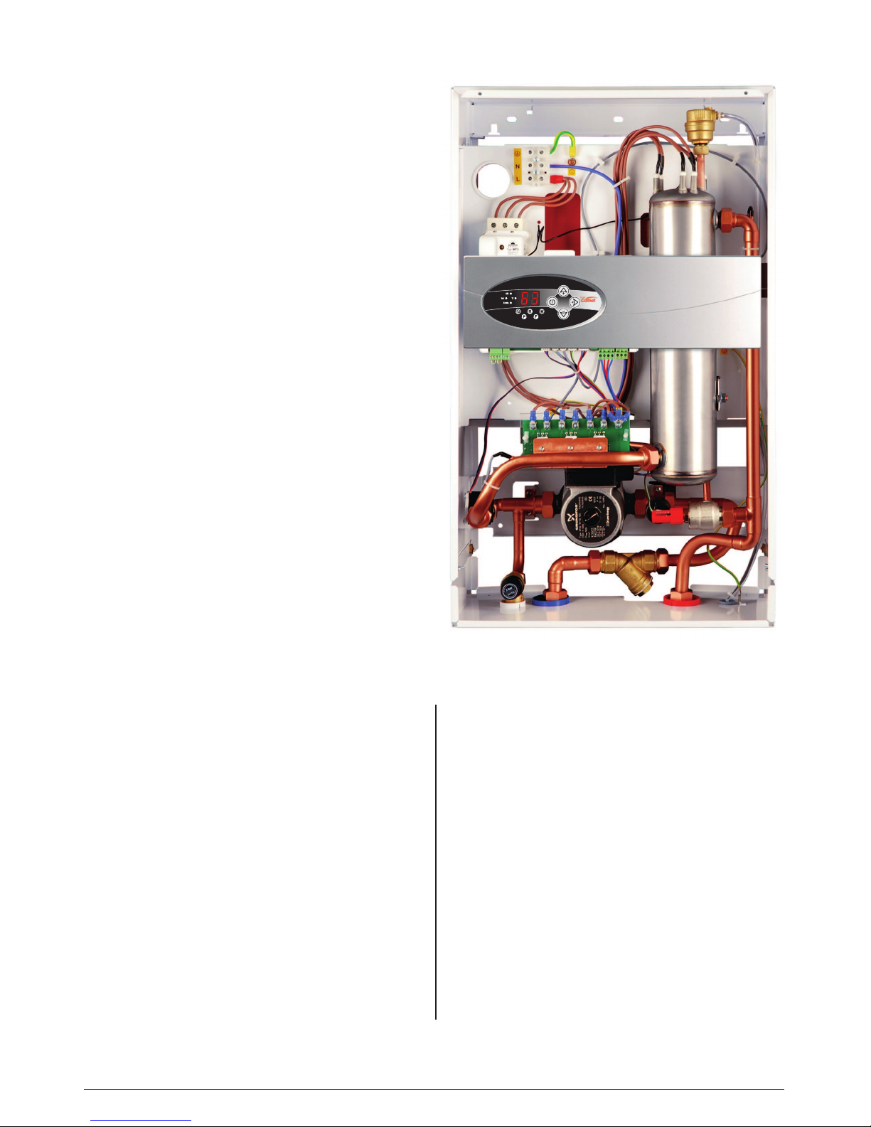
ELECTRIC BOILER INTERNAL LAYOUT
Figure 1
Electrical ‘mains’ input
connection block
[1] - StainlessSteelHeatExchanger
[2] - FlowSensor
[3] - PressureSensor
[4] - SafetyValve
[5] - CirculatingPump
[6] - SafetyTemperaturelimiter
[7] - Returnconnection
[8] - Flowconnection
[9] - PowerBoard
[10] - ControlModule
[11] - AutomaticVent
[12] - ExpansionVesselandconnection
[13] - By-passValve
[14] - MagneticFilter
PF - Internal‘mains’phaseconnectionsfromthePNconnectionblock
PN - Incoming‘mains’cableconnectionblock
WP - Electriccableaccess
M - Boilerfixingpoints
RP - RoomThermostatvoltfreeconnection
 Loading...