


AUTOTRIP
RCD TESTER
USER MANUAL

Safety information and explanation of symbols used
Caution read this manual for important safety information
The AUTOTRIP must only be used by suitably trained or competant
persons.
Before using the AUTOTRIP please read and fully understand these instructions paying
particular attention to the safety warnings. Do not use this tester in a manner other than
that described in this booklet.
Check the instrument case and test leads for damage before each use. If any
damage is noticed the unit should be withdrawn from service and returned to
place of purchase for repair.
The battery cover must be fitted and secure before using the instrument.
Always verify the continuity of the protective earthing conductors and
equipotential bonds before carrying out RCD testing.
Do not operate the meter around explosive gas, vapor, or dust.
Do not apply more than the rated voltage, (300V) as marked on the meter,
between terminals or between any terminal and earth ground.
The AUTOTRIP is rated at 300V Category III.
Exposed metal work in the installation should not be touched during testing.
Ensure when handling test probes and crocodile clips that fingers are always
behind the protective guards.
Do not change ranges by turning the rotary knob while a test is in progress.
Please note the polarity LED indicator is not able to determine N-PE supply
reversal.
Always perform a relevant risk assesment before testing and concider any
critical equipment and loads that maybe connected on the circuit under test
which will be turned off by tripping the RCD.

Symbols marked on the equipment
Caution refer to instruction manual and accompaning notes
Double Insulation
Equipment complies with current EU directives
ACMA mark
Batteries
Do not switch the instrument on or use it with the battery cover removed.
When installing batteries observe correct polarity do not mix old and new
batteries.
Dispose of used batteries in accordance with local regulations.
Never incinerate batteries.
For safety reasons the tester is shipped without batteries fitted.
To install or replace batteries
Replace batteries as soon as the low battery indication appears.
Switch the instrument off and disconnect from any electrical circuits.
Remove test leads.
Remove the small crosshead screw on the back of the instrument that retains
the battery cover and fit four Alkaline batteries type AA / LR6 in accordance with
the polarity shown.
Replace the battery cover and ensure it is secure before use.
The batteries should not be left in the instrument if it will not be used for an
extended period.
Overheating
Repetitive testing may generate heat within the instrument. If this occurs the hot
symbol is displayed and the instrument should be left to cool down before further
testing.
Maintenance
To clean the tester wipe with a damp cloth with a mild soap solution taking care
not to allow water ingress into the input terminals. Do not use solvents and do
not immerse. Allow the tester to fully dry before use.

Features of the AUTOTRIP
The AUTOTRIP is packed with design features that maximize both convenience and
safety. These include:
Large LCD display
To give the clearest results the AUTOTRIP uses a large auto-backlit LCD which
makes reading the test results easy even when used in poorly lit areas.
Auto shut down
To preserve battery life when not in use the AUTOTRIP incorporates an Auto-Off
function that powers the unit down after three minutes of inactivity. To resume
use after an Auto shut down a single press of any of the function buttons will
power up the unit.
Battery check
The battery charge condition is indicated on the LCD display.
For simplicity the tester is powered by just four conventional AA (LR6) alkaline
batteries.
Easy to locate
The test lead inputs are located on the top of the case allowing the tester to
stand vertically or be laid flat.
Hands Free
Most of the test functions can utilise the Hands-Free mode in which the tester
is primed to automatically start the test as soon as the probes are connected to
a circuit, thereby leaving your hands free to hold the test probes.
Socket wiring check
To protect both the user and the instrument against harm caused by accidental
connection to an incorrectly wired supply the tester will automatically check the
polarity upon connection to a live supply. If the wiring has been incorrectly
connected testing will be inhibited an alarm will sound along with a flashing red LED.
Please note the polarity LED indicator is not able to determine N-PE supply reversal.
Pass Fail Result
In addition to displaying the time taken for the RCD to trip the AUTOTRIP will also
indicate whether it has passed or failed the RCD requirements.
Auto Type II RCD Testing
To reduce the testing time the AUTOTRIP has two automatic test functions
which allows the operator to set the auto test sequence to run, resetting the RCD at the
distribution board during auto test cycle then returning to the instrument to recall the
results.
Quick Auto(2 Tests): 30mA x1 at 00 & 1800
Full Auto(6 Tests): 30mA x½, x1,x 5 at 0
0
& 1800
Audible tones
A simple selection of audible tones is used to supplement the visual display.
These help the user by providing intuitive feedback during testing. In addition
to warning about dangerous or unstable supply conditions they provide a very
quick confirmation that the measurement process is taking place and, upon
completion of the test, a warning if the results are likely to be regarded as a
failure.
The meaning of the tone for each individual function is covered in the table below.
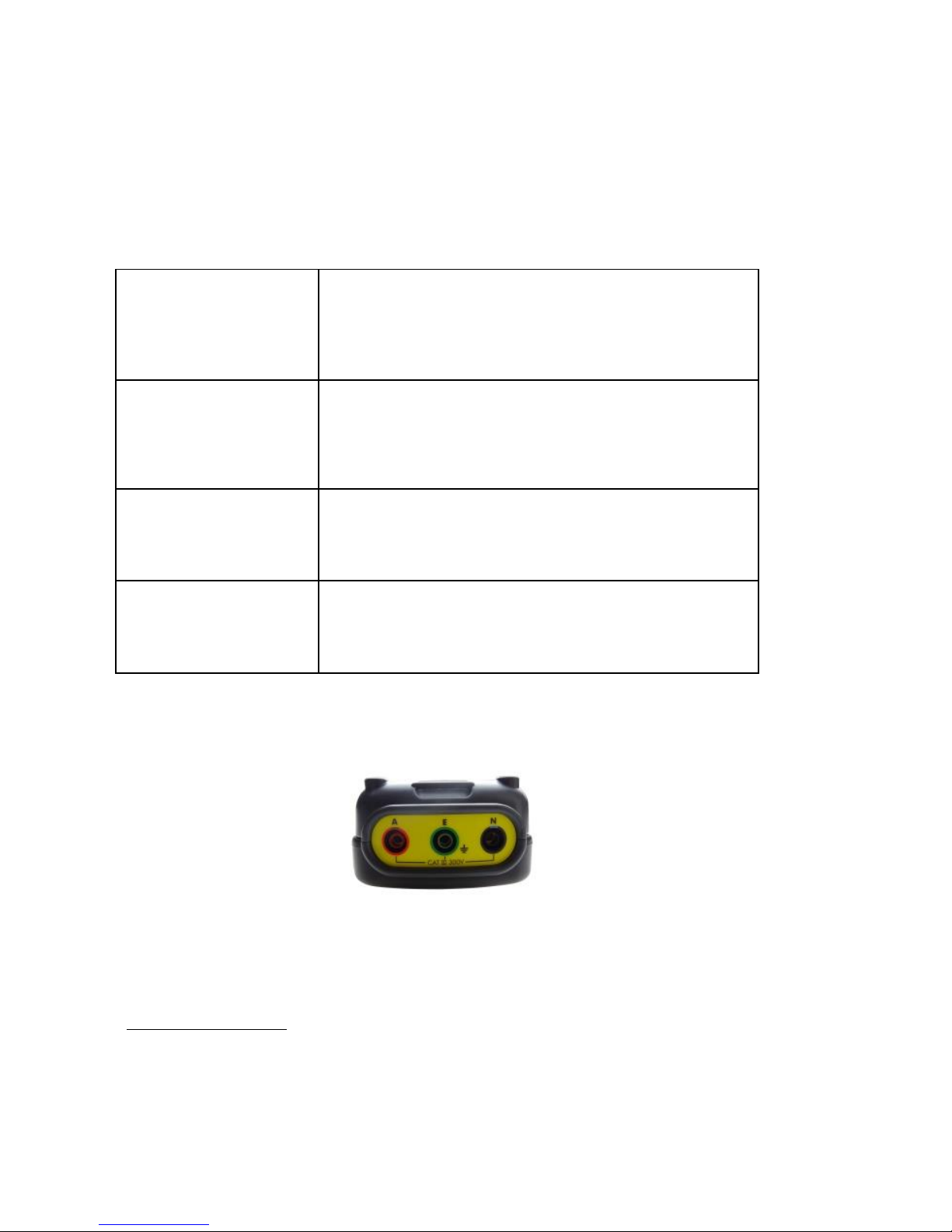
Test lead inputs
The test lead input terminals are Red Active terminal (marked A) the Black Neutral
terminal (marked N) and the Green Earth terminal (marked E).
Test lead configuration
The AUTOTRIP can be used with 2 different types of connecting lead.
1 Ref: TL-3P Mains lead; 3 x 4mm plugs to a 10A plug
Optional Accessory
2 Ref: TL-RGB 3-Pole distribution board test lead set; that can be fitted
with either prod tips or crocodile clips as required. The 3 colour coded prods/crocodile
clips of the test lead should be connected to the corresponding Line, Neutral
and Earth terminals.
The leads are an integral part of the tester set-up and should accompany the
tester when being returned for re-calibration or service.
Warning
A continuous 2 tone
alarm
An unsuitable supply configuration such as a
mains supply with incorrect polarity or having the
leads connected wrongly will be accompanied by
the Red Voltage/Polarity warning LED flashing
Wait-Test in progress
A steady beeping
sound
Emitted whilst a measurement is in progress. The
same tone is sounded when used in Hands Free
mode to indicate that continual measurement is
being made
Test completed
A single beep
Sounded upon completion of a measurement to
indicate that the result is being displayed
Alert
A short 2 tone alarm
Sounded when a test returns a result that is likely
to be regarded as a failure e.g.30mA RCD
trip time test gives a result of greater than 300ms
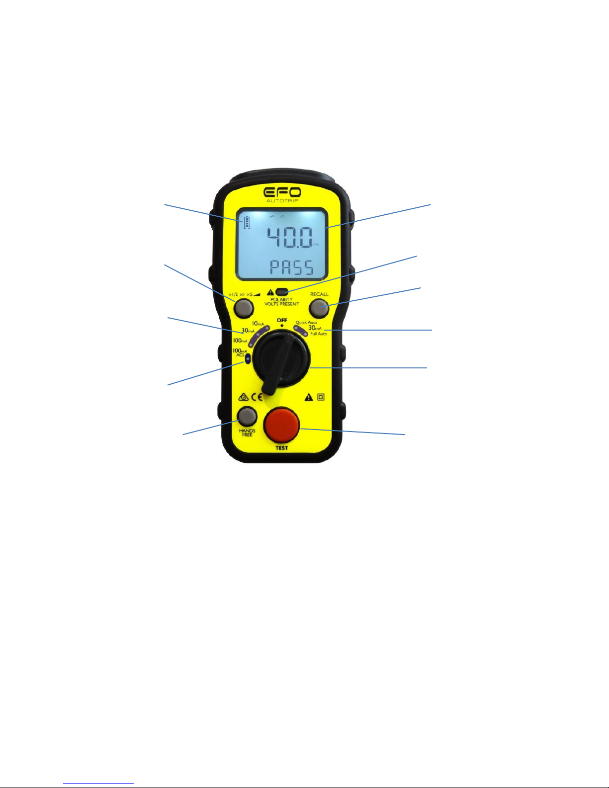
Overview of the switches and LCD display
The Primary display of the large LCD shows the result of the test being conducted. At
the same time a secondary display area shows supporting information e.g. Pass/Fail.
Mains supply wiring and voltage test
When first connected to a mains supply the AUTOTRIP will automatically conduct a
safety test to ensure that the Live, Neutral and Earth conductors are all
connected correctly and that the supply voltage is in the acceptable range
(195-253V). Please note the polarity LED indicator is not able to determine N-PE supply
reversal.
If all is well the VOLTAGE/POLARITY warning LED will light Green and the
supply voltage will be displayed in the primary display area.
In the event of a problem with either the mains voltage supply or reversed
connections the VOLTAGE/POLARITY warning LED will light Red, a warning
tone will be sounded and testing will be inhibited.
Battery Condition
Indication
Manual Select Test
Button
x ½, x1, x5 or Ramp
Select RCD Rating
10mA, 30mA, 100mA
Type AC
Start Test Button
Select RCD 100mA
Type ACS
Hands Free Function
Rotary Selector
LCD Backlit Display
Result Recall Button
Quick Auto & Full Auto
Tests
30mA Type II (AC)
Mains Polarity Check
Voltage Present Indication

RCD TEST FUNCTIONS
The AUTOTRIP will test Type I (10mA) & Type II (30mA) RCD
standard (AC) types across the full range of tests required and also RCD (S) type
100mA rated RCD’s.
Test Requirements
Each (AC) type RCD should be tested to ensure that it operates with a maximum
disconnection time indicated in the table when a fault at its rated current is introduced
for both the 00 & 1800 cycle. This is referred to as the x1 test.
Table referenced to 3.7.2.2 AS/NZS 3017:2007, always verify this complies with any
changes to the legislation or guidelines.
Recommended Additional Tests for 30mA RCD’s
It is not prone to ‘nuisance’ tripping and does not trip when a fault of half its rated current
is introduced. This is referred to as the x½ test.
In the case of an RCD rated at 30mA it should operate with a maximum disconnection
time of 40ms when a fault of five times itsrated current is introduced. This is referred to
as the x5 test.
For the reasons explained below all of the above tests have to be conducted at both 0°
and 180°.
100mA (S) Type
Type S: Selective or time delayed RCD's are used in applications where RCDs have
been connected in series to achieve discrimination between upstream and
downstream devices.
Residual Tripping
Current
Tripping Time
100mA Type S
Minimum 130ms
100mA Type S
Maximum 500ms
Sinusoidal Polarity (the 0° or 180° test)
RCD’s often operate with different reaction times depending upon whether the
fault is introduced during the positive or negative half cycle of the AC waveform.
Therefore to accurately determine the maximum response time of an RCD it is
necessary to test it twice at each given fault current, firstly with the fault introduced
during the positive half cycle 0° and secondly during the negative half cycle180°.
Residual Tripping
Current
Maximum Tripping
Time
10mA
40mS
30mA or Other
300mS

The AUTOTRIP takes care of this for you by alternating the start point of
consecutive tests at any given setting. If for example you have selected a test
at the rated trip current (x1) of a 30mA RCD, the first press of the test button
will apply a 30mA fault current starting on the positive half cycle (0°)
and display the result. A further press of the test button will carry out another
test at the same current but starting on the negative half cycle (180°).
RCD Test Procedure
Although fully protected against over voltage to 440V this tester should only be
used on a 240V AC supply.
Connect the 4mm plugs of the chosen test lead to the corresponding L, N & E
terminals of the AUTOTRIP and connect the other end to the socket or circuit
terminals under test.
If using the distribution board test lead set (TL-RGB) observe the correct polarity
by connecting the Red probe to the Live conductor, Black to Neutral and Green
to Earth.
Select the type and rating of the RCD to be tested with the rotary function
selector switch. (10mA, 30mA,100mA Type AC or 100mA Type S)
When first connected to a mains supply the AUTOTRIP will automatically conduct a
safety test to ensure that the Live, Neutral and Earth conductors are all
connected correctly and that the supply voltage is in the acceptable range
(195-253V).
If all is well the VOLTAGE/POLARITY warning LED will light Green and the
supply voltage will be displayed in the primary display area.
In the event of a problem with either the mains voltage supply or reversed
connections the VOLTAGE/POLARITY warning LED will light Red, a warning
tone will be sounded and testing will be inhibited.Do not proceed.
User Selected Manual Tests
x½
The recommended order of tests is firstly at x½ the rated current followed by a
x1 test at the rated current and finally, for 30mA RCD’s only x5 the rated current.
The default test parameter for the selected current
multiplier x½ is 0° for the phase polarity this
will be automatically selected for the first test. This will
be displayed on the LCD display along with the
Line-Neutral voltage.
Press the test button and a test will be conducted at the
selected settings. If successful and the RCD has failed
to trip a single beep will sound and the main display
will be similar to figure 5.
Displaying 1st test result of x ½ test 0° (figure 5)

The main display shows that the fault current was applied for over 2000
milliseconds (2 seconds) without tripping the RCD. The secondary display
confirms that this passes the requirements.
In the event of the RCD failing the test and tripping at half the
rated current the main display will show the trip time and the secondary display
will show ‘FAIL’. A short 2 tone alert will also sound.
After displaying the result for a few seconds the tester
will switch to the 180°phase polarity setting in readiness
for the next test. (Figure 6)
Changed polarity displaying line voltage ready for 2nd test x ½ test 180° (figure 6)
When both tests have been conducted at the x½ setting press the multiplier
button to change the test current to the x1 setting.
x1
Press the test button to conduct a test at the x1 setting at 0°. The result will be
shown as a pass if a 30mA RCD trips within 300ms. After displaying the result for a few
seconds the tester will switch to the 180° phase polarity setting in readiness for
the second test at the x1 current setting.
x5
If the 30mA setting has been selected a x5 current option will be available by
using the multiplier button. This option is not available for other
ratings.
Ramp Test
The AUTOTRIP also includes a diagnostic Ramp test feature. In this mode rather
than applying a steady fault current and measuring the time taken for the RCD
to trip, the AUTOTRIP gradually increases the fault current and identifies the level of
leakage at which the RCD trips.
This is particularly useful in diagnostic testing of circuits where nuisance
tripping is a problem and helps to identify the difference between an over
sensitive RCD and excessive leakage from poor insulation or equipment with
high leakage.

Use the rotary switch to select the rating of the RCD.
Press the multiplier button until the ramp symbol is displayed.
Press the test button to start the test. The fault current applied will increment in
3mA steps until the RCD trips.
If nuisance tripping on a circuit is a problem this function can be used to retest
the RCD with other appliances systematically connected and removed.
For example a 30mA RCD may trip at 12mA on ramp test with an appliance
connected and then at 27mA with the appliance removed. You will know that
the appliance is leaking approximately 15mA.
Automatic Tests
30mA Quick Auto Test
Turn the rotary selector to the ‘30mA QUICK AUTO’ setting, press the test button
and the tester will conduct 2 tests: (30mA x1 test at both the 00 and 1800 half cycle).
All that is required is to remain at the switchboard and reset the RCD after it trips.
Upon completion of the auto test routine the results for each setting can be
recalled by using the RECALL button to cycle through the routine.
The AUTOTRIP will also indicate whether it has passed or failed the RCD requirements.
30mA Full Auto Test
Turn the rotary selector to the ‘30mA Full AUTO’ setting, press the test button and the
tester will conduct 6 tests: (30mA x½, x1,x5 at both the 00 and 1800 half cycle)
All that is required is to remain at the switchboard and reset the RCD each time it trips.
Upon completion of the auto test routine the results for each setting can be recalled by
using the RECALL button to cycle through the routine.
AUTOTRIP will also indicate whether it has passed or failed the RCD requirements.
Hands Free Testing
The hands free feature can be used where repeat testing is required. To enable
hands free simply press the Hands Free button once.
The ‘HANDSFREE’ annunciator will appear flashing on the LCD and will coniine to do
so until cancelled by a further press of the Hands Free button or by changing the
selector switch.
When the HANDSFREE annunciator is flashing all you need to do is connect the test
lead to a mains supply and the test will be automatically carried out.
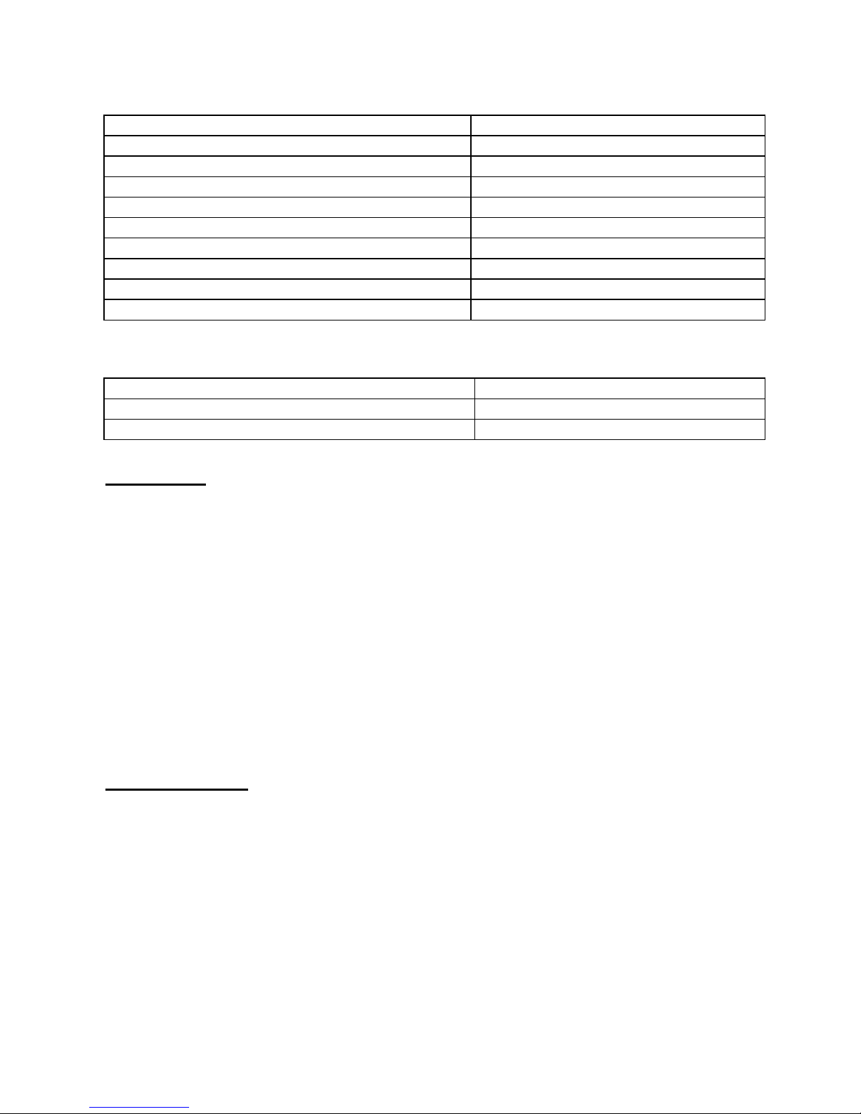
Specifications and tolerances
RCD TEST TOLERANCES
Supply Voltage Range
195 to 253V AC 50-60Hz
Nominal Currents
10mA,30mA,100mA
Test Current Accuracy x 1/2
+0% - 10%
Test Current Accuracy x 1
+10% -0%
Test Current Accuracy x 5 (30mA only)
+/- 5%
Test Current Accuracy Ramp
+/- 5% of rated IN
Trip Time Accuracy to 1.999s
+/- (1% +1ms)
Fault / Touch Voltage
50V
Over Voltage Protection
440V
RCD Trip Time
Measurement Range
5ms – 1999ms
Operating Range Per EN61557
38ms – 1999ms
Standards
To meet 300V CATIII
The AUTOTRIP complies fully with the requirements of EN61010 and complies with
the sections of EN61557, Electrical Safety in Low Voltage Systems up to 1000V AC
and 1500V DC as listed below.
BS EN 61010-2-030:2010 (Safety)
BS EN 61326-2-2:2013 (EMC)
BS EN 61557-1:2007 (General performance)
BS EN 61557-6:2007 (RCD performance)
Environmental
Operating Temperature Range 0C to 40C
Storage Temperature Range -10C to 60C
Operating Humidity 80% @ 31C to 50% @40C

For repair and calibration please contact place of purchase.
Electrical Factory Outlet Pty Ltd
PO Box 701, Rochedale South, QLD 4123
PH +61 7 3411 0303
E-mail: sales@electricalfactory.com.au
www.electricalfactory.com.au
 Loading...