

PLUS96 Y
2
PLUS96-P Y
PLUS96-485 Y
PLUS96
PLUS96-P
PLUS96-485
Instructions
English
Akse declares that its range of instruments complies with the EMC 89/336/EEC
directive and satisfies the requirements of the following standards: EMISSION = EN
50081-1 1992; EN 55022-CLASS B CISPR 22; IMMUNITY = EN 50082-1
(light industry) 1992; SAFETY IEC 61010.
1 SAFETY
This instrument was developed and tested in compliance with IEC 1010 and class 2 VDE 411
standards, conforming to the VDE0110 group C insulation standards, for rated voltages lower
than or equal to 500 VAC rms (phase-neutral wire).
In order to maintain these conditions and to guarantee safe usage, the user must comply with the
warnings and symbols outlined in the following instructions.
Upon receipt of the instrument and before installing it, make sure that it is sound and did not suffer
any damage during shipment
First, make sure that the rated voltage corresponds to the mains voltage and then install the
instrument
The instrument power supply must not be grounded
The instrument is not equipped with a safety fuse on the power supply. Therefore, it must be
protected by the operator.
Only qualified and authorised personnel is authorised to carry out repairs and/or maintenance
operations.
If you fear that the instrument is no longer safe, disable it and make sure it cannot be used
unintentionally.
The operation is no longer safe:
1 ) If the instrument shows evident damage
2 ) If the instrument does not work
3 ) After a long period of non-use under unfavourable conditions
4 ) After serious damage suffered during shipment
1.1 OPERATOR SAFETY
Read the instructions thoroughly before installing and using the instrument.
The instrument described in this instruction manual is deemed to be used by duly trained personnel.
Only qualified and authorised personnel is authorised to carry out repairs and/or maintenance
operations.
For the correct and safe use of the instrument and for the maintenance and/or repairs, it is extremely
important that the persons in charge follow the normal safety procedures.
1.2 SYMBOLS
READ THE INSTRUCTIONS
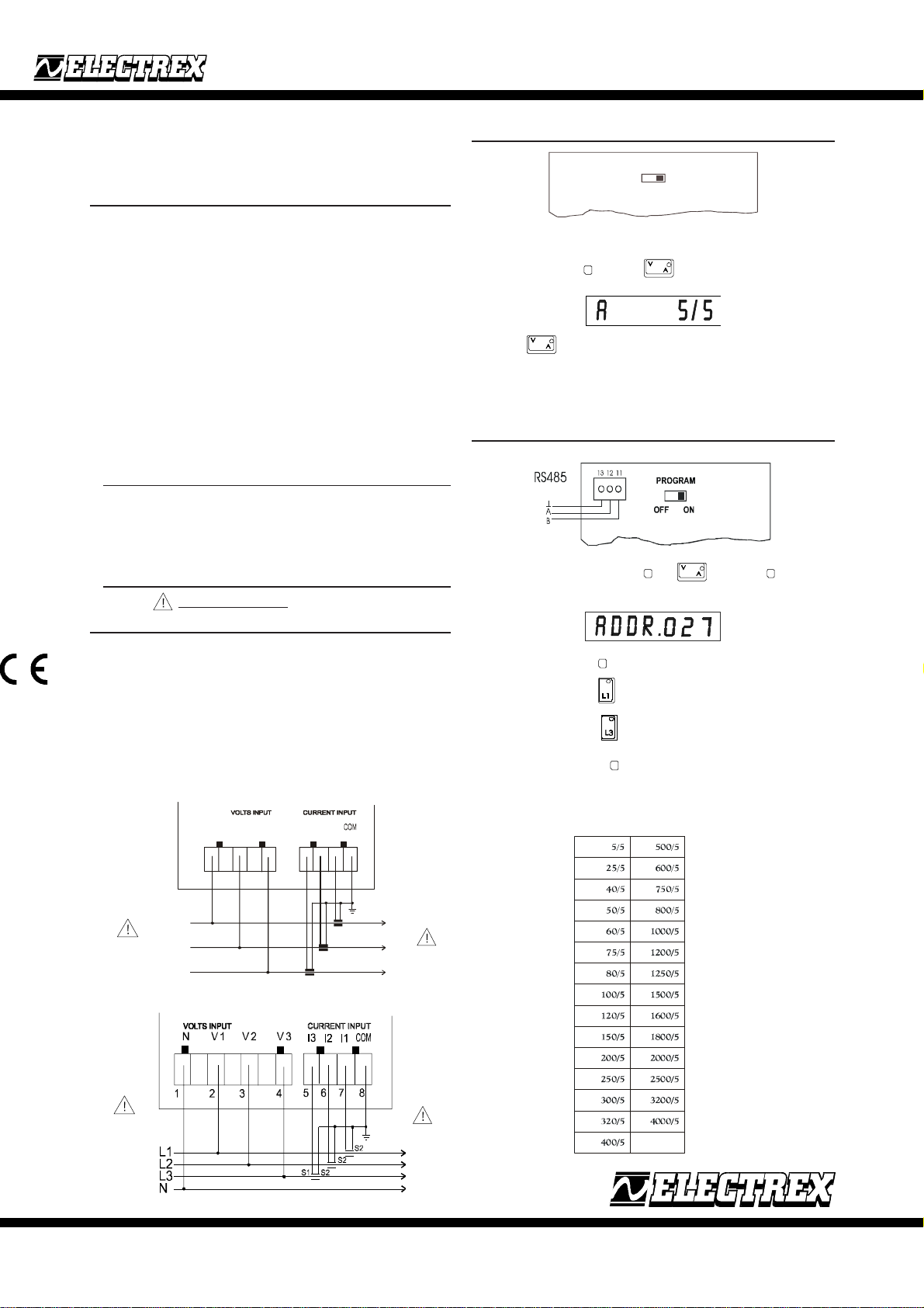
2 CONNECTION OF THE VOLTAGE AND CURRENT MEASURES
The instrument is auto-fed by V1 and V2 mains voltages. Use cables with a max. section of 2.5
mm2 and connect them to the terminals identified with VOLTS INPUT, according to the wiring
diagram shown in the figure. WARNING: threshold: 60-500VAC phase-phase. You need to use
3 CTs with a 5A secondary. Connect the amperometric signal from the CTs to the terminals
marked with CURRENT INPUT according to the diagram shown in the figure. Use cables with
the proper section according to the used CT capacity and to the distance.
Note: the CT secondary must always be short-circuited when it is not connected to the instrument
to avoid damage and risks for the operator.
ALWAYS KEEP TO THE PHASE MATCHING BETWEEN VOLTMETRIC AND AMPEROMETRIC
SIGNALS. Failure to follow both the matching and the wiring diagrams may lead to measurement
errors.
Standard auto-fed model
3 INSTRUMENT PROGRAMMING
P R O G R A M
O N O F F
When the instrument is powered up, WAIT is shown on the display. After a few seconds the
instrument shows the measure (the LED provided on the key is ON). To enter the programming
mode, selector switch located on the rear of the instrument must be set to ON position, press the
key to access programming and the key simultaneously. Selection of ATs is shown
on the display.
Press the key to select the ratio of available ATs (see AT table)
Once the selection has been completed, press the programming key.
The default settings envisages:
- CT transforming ratio = 5/5
After programming, set the selector switch located on the rear of the instrument to 0 if you wish
to disable the hidden key.
4 RS485 OUTPUT CONNECTION
After entering the programming page through and , press the key once more and
the address of the instrument will be displayed. The default address set by the manufacturer upon
delivery is:
.
It can be changed through: key to select the digit
Key to increase the digit
Key to decrease the digit
The flashing digit is active.
To exit the programming, press key a fourth time.
The maximum selectable number is 247.
CT used
340 ÷ 420 VAC
FASE-FASE
200 ÷ 240 VAC
FASE-NEUTRAL
Rev. 06/01
V1 V2 V3 I3 I2 I1
1 2 3
L1
L2
L3
4 wires model
5 6 7 8
S1
P1
S1
P2
P1
S1S2S2
P1
P
S2
P2
MAX 5 A
MAX 5 A
AKSE S.r.l. via Aldo Moro, 39 - 42100 Reggio Emilia (RE) - Italy - Tel. +39.0522.924244 Fax. +39.0522.924245
PLUS96 Y
PLUS96-P Y
PLUS96-485 Y
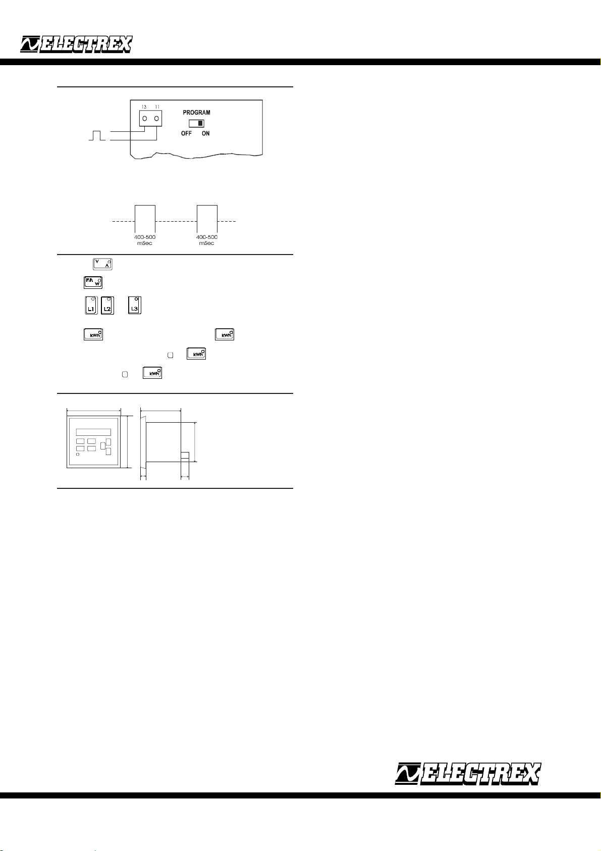
5 P OUTPUT CONNECTION
Featuring pulse output for transmission of energy data. Each output is equivalent to 1kWh. The
output is a galvanically isolated OPTO MOS long life solid state relay rated at 250V, 100mA AC/
DC. The duration of the output pulse ranges between 400-500-mSec. as recommended by standards.
6 DESCRIPTION OF THE KEYS TO SELECT THE MEASURES
Press the key to show the three-phase voltage and current.
Press key to display the three-phase instantaneous power and power factor.
Press keys and to display voltage, current, instantaneous power and the power
factor of L1, L2 and L3, respectively.
Press key to display the active energy meter and key to display the reactive
PLUS96
PLUS96-P
PLUS96-485
Instructions
English
energy meter. Kwh values are zeroed if keys and are pressed simultaneously. Kvarh
values are zeroed if keys and are pressed simultaneously.
7 DIMENSIONS (MM)
96
96
8 TECHNICAL SPECIFICATIONS
Inputs: Voltmetric: 500VAC 20-800 Hz
Inputs overload: V: max. 800 Vrms, A: max. 7 Arms
Connection: Three phase delta networks (3 phases without neutral wire)
Accuracy: ≤0,5% of the reading x V and I, 1% of the reading x P.
Measures: R.M.S. up to the 16th harmonic.
Number of scales: 1 voltage scale, 2 current scales
Weight: 320 grams
Protection class: Front= IP40
Temperature range: -10°C + 50°C
Relative humidity: RH: max. 90%. Condensation: not allowed.
Insulation: according VDE 0110, group C for rated voltages of 500 VAC rms.
Input impedance: 2 Mohm
Amperometric: 0-5 A from external CTs (3 CTs are required)
Three phase STAR connection (3 phase + neutral )
70
89
9
14
Panel drilling template
Rev. 06/01
AKSE S.r.l. via Aldo Moro, 39 - 42100 Reggio Emilia (RE) - Italy - Tel. +39.0522.924244 Fax. +39.0522.924245
 Loading...