


COPYRIGHT
Electrex is a trademark of Akse S.r.l. All rights reserved.
It is forbidden to duplicate, adapt, transcript this document without Akse written authorization,
except when regulated accordingly by the Copyright Laws.
WARRANTY
This product is covered by a warranty against material and manufacturing defects for a
period of 24 months period from the manufacturing date.
The warranty does not cover the defects that are due to:
• Negligent and improper use
• Failures caused by atmospheric hazards
• Acts of vandalism
• Wear out of materials
• Firmware upgrades
Akse reserves the right, at its discretion, to repair or substitute the faulty products
The warranty is not applicable to the products that will result defective in consequence of a
negligent and improper use or an operating procedure not contemplated in this manual.
RETURN AND REPAIR FORMALITIES
Akse accepts the return of instruments for repair only when authorized in advance. The
transport costs are at customer charge.
RE-SHIPPING OF REPAIRED PRODUCT
The terms for re-shipment of repaired products are ex-works, i.e. the transport costs are
at customer charge.
Products returned as detective but found to be perfectly working by our laboratories, will
be charged a fl at fee to account for checking and testing time irrespective of the warranty
terms.
SAFETY
This instrument was manufactured and tested in compliance with IEC 61010 class 2
standards for operating voltages up to 250 VAC rms phase to neutral.
In order to maintain this condition and to ensure safe operation, the user must comply with
the indications and markings contained in the following instructions:
• When the instrument is received, before starting its installation, check that it is
intact and no damage occurred during transport.
• Before mounting, ensure that the instrument operating voltages and the mains
voltage are compatible then proceed with the installation.
• The instrument power supply needs no earth connection.
• The instrument is not equipped with a power supply fuse; a suitable external
protection fuse must be foreseen by the contractor.
• Maintenance and/or repair must be carried out only by qualifi ed, authorized
personnel
• If there is ever the suspicion that safe operation is no longer possible, the instrument
must be taken out of service and precautions taken againstits accidental use.
• Operation is no longer safe when:
1) There is clearly visible damage.
2) The instrument no longer functions.
3) After lengthy storage in unfavorable conditions.
4) After serious damage occurred during transport
The instruments must be installed in respect of all the local regulations.
OPERATOR SAFETY
Warning: Failure to observe the following instructions may lead to a serious danger of
death.
• During normal operation dangerous voltages can occur on instrument terminals and
on voltage and current transformers. Energized voltage and current transformers
may generate lethal voltages. Follow carefully the standard safety precautions while
carrying out any installation or service operation.
• The terminals of the instrument must not be accessible by the user after the installation.
The user should only be allowed to access the instrument front panel where the
display is located.
• Do not use the digital outputs for protection functions nor for power limitation functions.
The instrument is suitable only for secondary protection functions.
• The instrument must be protected by a breaking device capable of interrupting both
the power supply and the measurement terminals. It must be easily reachable by the
operator and well identifi ed as instrument cut-off device.
• The instrument and its connections must be carefully protected against short-circuit.
Precautions: Failure to respect the following instructions may irreversibly damage to the
instrument.
• The instrument is equipped with PTC current limiting device but a suitable external
protection fuse should be foreseen by the contractor.
• The outputs and the options operate at low voltage level; they cannot be powered by
any unspecifi ed external voltage.
• The application of currents not compatible with the current inputs levels will damage
to the instrument.
Further documentation may be downloaded from our web site www.electrex.it.
This document is owned by company AKSE that reserves all rights.
DECLARATION OF CONFORMITY
Akse hereby declares that its range of products complies with the following directives EMC
2014/30/EU, 2014/35/EU and complies with the following product’s standard CEI EN
61326 - Ed. 2.0 (2012) – IEC 61326 - Ed. 2.0 (2012), CEI EN 61010- Ed. 3 (2010) – IEC
61010- Ed. 3 (2010). The product has been tested in the typical wiring confi guration and
with peripherals conforming to the EMC directive and the LV directive.
!
ATTO D4
INSTALLATION INSTRUCTIONS
The instrument is programmed with the following default values:
PAGE MENU DISPLAYED AVAILABLE PARAMETERS DEFAULT
PASSWORD 0000 ... 9999 0000
RS485
RS 485 ADDRESS 1 ... 247 27
Comm. Speed 2400, 4800, 9600, 19200, 38400 38400
Data Bit 7 o 8 8
Parity N = no parity, E =even parity, O = odd parity N
Bit of stop 1 o 2 2
NETWORK
Type (note n.1) 3PH-3W-2CT, 3PH-4W, 2PH-2W, 1PH-2W 3PH-4W
Export NO, YES NO
CT 10000/1 o 5 5/5
VT 400000/300 1/1
AVG-MD TIME (note n.2)
POWERS 1...60 (minutes) 15
CURRENTS 1...60 (minutes) 8
ALARM 1 / A (note n.11)
MODE (note n.3) Normal, 1-OF-3, 3-OF-3, DERIV, UNBAL NORMAL
TYPE (note n.4) MAX, MIN MIN
MEAS (note n.5)
Controlled measure. See table n.1 for register
selection
200
THRE (note n.5) Threshold value 0
ALARM 1 / B
HYST 1...100 (%) 1
DELAY 1...99 (seconds) 1
AVG (note n.6) 1...99 (seconds) 1
OUT (note n.7) Normal, Hold, Pulse-L, Pulse-S NORMAL
ALARM 2 / A (note n.11)
MODE (note n.3) Normal, 1-OF-3, 3-OF-3, DERIV, UNBAL NORMAL
TYPE (note n.4) MAX, MIN MIN
MEAS (note n.5)
Controlled measure. See table n.1 for register
selection
200
THRE (note n.5) Threshold value 0
ALARM 2 / B
HYST 1...100 (%) 1
DELAY 1...99 (seconds) 1
AVG (note n.6) 1...99 (seconds) 1
OUT (note n.7) Normal, Hold, Pulse-L, Pulse-S NORMAL
ALARM 3 / A (note n.11)
MODE (note n.3) Normal, 1-OF-3, 3-OF-3, DERIV, UNBAL NORMAL
TYPE (note n.4) MAX, MIN MIN
MEAS (note n.5)
Controlled measure. See table n.1 for register
selection
200
THRE (note n.5) Threshold value 0
ALARM 3 / B
HYST 1...100 (%) 1
DELAY 1...99 (seconds) 1
AVG (note n.6) 1...99 (seconds) 1
OUT (note n.7) Normal, Hold, Pulse-L, Pulse-S NORMAL
ALARM 4 / A (note n.11)
MODE (note n.3) Normal, 1-OF-3, 3-OF-3, DERIV, UNBAL NORMAL
TYPE (note n.4) MAX, MIN MIN
MEAS (note n.5)
Controlled measure. See table n.1 for register
selection
200
THRE (
note n.5) Threshold value 0
ALARM 4 / B
HYST 1...100 (%) 1
DELAY 1...99 (seconds) 1
AVG (note n.6) 1...99 (seconds) 1
OUT (note n.7) Normal, Hold, Pulse-L, Pulse-S NORMAL
DIGITAL OUT 1 (note n.8)
MODE PULSE, ALARM, REMOTE PULSE
POLARITY NO, NC NO
PULSE OUT 1
MEAS (note n.9)
P-IMP, QL-IMP, QC-IMP, S-IMP, P-EXP,
QL-EXP, QC-EXP, S-EXP
P-IMP
PRIMARY (note n.10) YES, NO YES
WEIGHT 1...100000000 (Wh/100) 100000
WIDTH 50ms...1S 500
DIGITAL OUT 2 (note n.8)
MODE PULSE, ALARM, REMOTE PULSE
POLARITY NO, NC NO
PULSE OUT 2
MEAS (note n.9)
P-IMP, QL-IMP, QC-IMP, S-IMP, P-EXP,
QL-EXP, QC-EXP, S-EXP
QL-IMP
PRIMARY (note n.10) YES, NO YES
WEIGHT 1...100000000 (Wh/100) 100000
WIDTH 50ms...1S 500
MECHANICAL CHARACTERISTICS
Enclosure Self-extinguishing plastic material class V0
Protection degree IP40 on front panel
Dimensions 70 x 90 x 58 mm (4 DIN modules)
VOLTAGE INPUT
Direct Up to 300 Vrms phase-neutral or 519 Vrms phase to phase
With external PT(VT) Primary: programmable (max. 400 kV)
Secondary: programmable (max. 300 V)
Overload: 900 Vrms phase to phase for 1 sec
Power supply 230/240Vac +/- 10% 50/60Hz
Self consumption < 3VA
MODELS
PFA7411-02 ATTO D4 RS485 230-240V
TRANSDUCER / ANALYZER
PFA7411-12 ATTO D4 RS485 230-240V 1DI 2DO
TRANSDUCER / ANALYZER
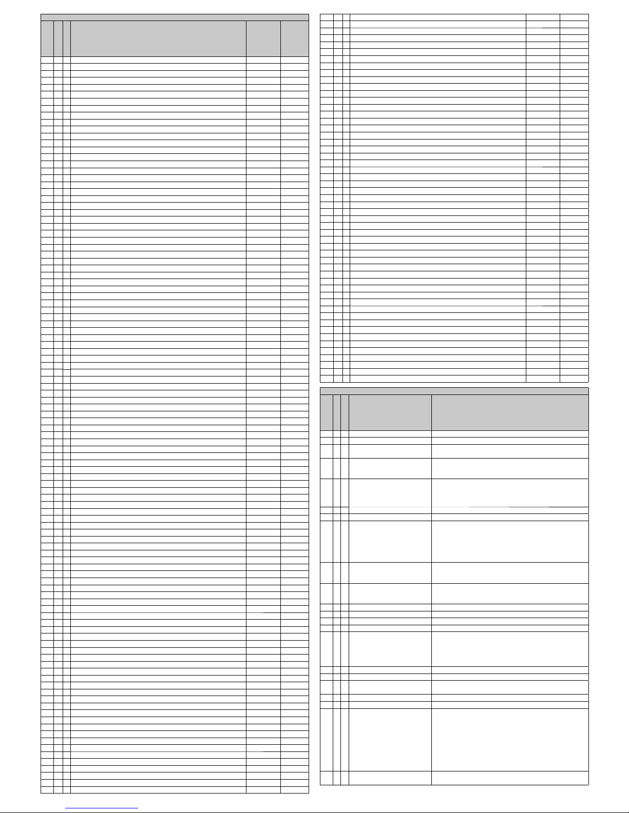
INPUT REGISTERS
Address
n° Register
Type *
Description
Symbol
Unit
200 2 F Phase to Neutral Voltage, THD THD U1N [%]
202 2 F Phase to Neutral Voltage, THD THD U2N [%]
204 2 F Phase to Neutral Voltage, THD THD U3N [%]
206 2 F Phase to Phase Voltage, THD THD U12 [%]
208 2 F Phase to Phase Voltage, THD THD U23 [%]
210 2 F Phase to Phase Voltage, THD THD U31 [%]
212 2 F Phase Current, THD THD I1 [%]
214 2 F Phase Current, THD THD I2 [%]
216 2 F Phase Current, THD THD I3 [%]
218 2 F Frequency of U1N f [Hz]
220 2 F Phase to Neutral Voltage, RMS Amplitude U1N [V]
222 2 F Phase to Neutral Voltage, RMS Amplitude U2N [V]
224 2 F Phase to Neutral Voltage, RMS Amplitude U3N [V]
226 2 F Phase to Phase Voltage, RMS Amplitude U12 [V]
228 2 F Phase to Phase Voltage, RMS Amplitude U23 [V]
230 2 F Phase to Phase Voltage, RMS Amplitude U31 [V]
232 2 F Phase Current, RMS Amplitude I1 [A]
234 2 F Phase Current, RMS Amplitude I2 [A]
236 2 F Phase Current, RMS Amplitude I3 [A]
238 2 F Neutral Current, RMS Amplitude IN [A]
240 2 F Phase Active Power (+/-) P1 [W]
242 2 F Phase Active Power (+/-) P2 [W]
244 2 F Phase Active Power (+/-) P3 [W]
246 2 F Phase Reactive Power (+/-) Q1 [var]
248 2 F Phase Reactive Power (+/-) Q2 [var]
250 2 F Phase Reactive Power (+/-) Q3 [var]
252 2 F Phase Apparent Power S1 [VA]
254 2 F Phase Apparent Power S2 [VA]
256 2 F Phase Apparent Power S3 [VA]
258 2 F Phase Power Factor (+/-) PF1 [-]
260 2 F Phase Power Factor (+/-) PF2 [-]
262 2 F Phase Power Factor (+/-) PF3 [-]
264 2 F Phase to Neutral Voltage, Mean THD THD Ul [%]
266 2 F Phase to Phase Voltage, Mean THD THD UD [%]
268 2 F Phase Current, Mean THD THD I [%]
270 2 F Phase to Neutral Voltage, Mean RMS Amplitude Ul [V]
272 2 F Phase to Phase Voltage, Mean RMS Amplitude UD [V]
274 2 F Three phase current, RMS Amplitude I [A]
276 2 F Total active power (+/-) PS [W]
278 2 F Total reactive power (+/-) QS [var]
280 2 F Total apparent power SS [VA]
282 2 F Total power factor (+/-) PFS [-]
284 2 F Internal Temperature, °C T [°C]
286 2 F Internal Temperature, °F T [°F]
288 2 F Phase to Neutral Voltage, RMS Amplitude, MIN U1N MIN [A]
290 2 F Phase to Neutral Voltage, RMS Amplitude, MIN U2N MIN [A]
292 2 F Phase to Neutral Voltage, RMS Amplitude, MIN U3N MIN [A]
294 2 F Phase to Neutral Voltage, RMS Amplitude, MAX U1N MAX [A]
296 2 F Phase to Neutral Voltage, RMS Amplitude, MAX U2N MAX [A]
298 2 F Phase to Neutral Voltage, RMS Amplitude, MAX U3N MAX [A]
300 2 F Phase to Phase Voltage, RMS Amplitude, MIN U12 MIN [A]
302 2 F Phase to Phase Voltage, RMS Amplitude, MIN U23 MIN [A]
304 2 F Phase to Phase Voltage, RMS Amplitude, MIN U31 MIN [A]
306 2 F Phase to Phase Voltage, RMS Amplitude, MAX U12 MAX [A]
308 2 F Phase to Phase Voltage, RMS Amplitude, MAX U23 MAX [A]
310 2 F Phase to Phase Voltage, RMS Amplitude, MAX U31 MAX [A]
312 2 F Phase Current, RMS Amplitude, MAX I1 MAX [A]
314 2 F Phase Current, RMS Amplitude, MAX I2 MAX [A]
316 2 F Phase Current, RMS Amplitude, MAX I3 MAX [A]
318 2 F Neutral Current, RMS Amplitude, MAX IN MAX [A]
320 2 F Phase Active Power, Import, MAX P1+ MAX [A]
322 2 F Phase Active Power, Import, MAX P2+ MAX [A]
324 2 F Phase Active Power, Import, MAX P3+ MAX [A]
326 2 F Phase Active Power, Export, MAX P1- MAX [A]
328 2 F Phase Active Power, Export, MAX P2- MAX [A]
330 2 F Phase Active Power, Export, MAX P3- MAX [A]
332 2 F Phase Current, RMS Amplitude, AVG I1 AVG [A]
334 2 F Phase Current, RMS Amplitude, AVG I2 AVG [A]
336 2 F Phase Current, RMS Amplitude, AVG I3 AVG [A]
338 2 F Phase Current, RMS Amplitude, MD I1 MD [A]
340 2 F Phase Current, RMS Amplitude, MD I2 MD [A]
342 2 F Phase Current, RMS Amplitude, MD I3 MD [A]
344 2 F Total imported active power, AVG P+ AVG [W]
346 2 F Total imported inductive power, AVG Qind+ AVG [var]
348 2 F Total imported capacitive power, AVG Qcap+ AVG [var]
350 2 F Total imported apparent power, AVG S+ AVG [VA]
352 2 F Total exported active power, AVG P- AVG [W]
354 2 F Total exported inductive power, AVG Qind- AVG [var]
356 2 F Total exported capacitive power, AVG Qcap- AVG [var]
358 2 F Total exported apparent power, AVG S- AVG [VA]
360 2 F Total imported active power, MD P+ MD [W]
362 2 F Total imported inductive power, MD Qind+ MD [var]
364 2 F Total imported capacitive power, MD Qcap+ MD [var]
366 2 F Total imported apparent power, MD S+ MD [VA]
368 2 F Total exported active power, MD P- MD [W]
370 2 F Total exported inductive power, MD Qind- MD [var]
372 2 F Total exported capacitive power, MD Qcap- MD [var]
374 2 F Total exported apparent power, MD S- MD [VA]
376 2 F External Pulse Counter, With Weight, Total counter or Tariff T1 CNT1 S
384 2 F External Pulse Counter, With Weight, Partial Counter or Tariff T2 CNT1 P
392 2 I External Pulse Counter, Total counter or Tariff T1 CNT1 S [-]
400 2 I Lifetimer, Total counter TIME S [s]
402 2 I External Pulse Counter, Partial Counter or Tariff T2 CNT1 P [-]
410 2 I Lifetimer, Partial Counter or Conditional Counter TIME P [s]
412 2 I Total imported active energy, Total counter or Tariff T1 Ea S + [kWh/10]
414 2 I Total imported inductive energy, Total counter or Tariff T1 Er Ind S + [kvarh/10]
416 2 I Total imported capacitive energy, Total counter or Tariff T1 Er Cap S + [kvarh/10]
418 2 I Total imported apparent energy, Total counter or Tariff T1 Es S + [kVAh/10]
420 2 I Total exported active energy, Total counter or Tariff T1 Ea S - [kWh/10]
422 2 I Total exported inductive energy, Total counter or Tariff T1 Er Ind S - [kvarh/10]
424 2 I Total exported capacitive energy, Total counter or Tariff T1 Er Cap S - [kvarh/10]
426 2 I Total exported apparent energy, Total counter or Tariff T1 Es S - [kVAh/10]
428 2 I Total imported active energy, Partial Counter or Tariff T2 Ea P + [kWh/10]
430 2 I Total imported inductive energy, Partial Counter or Tariff T2 Er Ind P + [kvarh/10]
432 2 I Total imported capacitive energy, Partial Counter or Tariff T2 Er Cap P + [kvarh/10]
434 2 I Total imported apparent energy, Partial Counter or Tariff T2 Es P + [kVAh/10]
436 2 I Total exported active energy, Partial Counter or Tariff T2 Ea P - [kWh/10]
438 2 I Total exported inductive energy, Partial Counter or Tariff T2 Er Ind P - [kvarh/10]
440 2 I Total exported capacitive energy, Partial Counter or Tariff T2 Er Cap P - [kvarh/10]
442 2 I Total exported apparent energy, Partial Counter or Tariff T2 Es P - [kVAh/10]
444 2 I Phase imported active energy Ea+ L1 [kWh/10]
446 2 I Phase imported active energy Ea+ L2 [kWh/10]
448 2 I Phase imported active energy Ea+ L3 [kWh/10]
450 2 I Phase imported inductive energy Er Ind + L1 [kvarh/10]
452 2 I Phase imported inductive energy Er Ind + L2 [kvarh/10]
454 2 I Phase imported inductive energy Er Ind + L3 [kvarh/10]
456 2 I Phase imported capacitive energy Er Cap + L1 [kvarh/10]
458 2 I Phase imported capacitive energy Er Cap + L2 [kvarh/10]
460 2 I Phase imported capacitive energy Er Cap + L3 [kvarh/10]
462 2 I Phase imported apparent energy Es + L1 [kvarh/10]
464 2 I Phase imported apparent energy Es + L2 [kvarh/10]
466 2 I Phase imported apparent energy Es + L3 [kvarh/10]
468 2 I Phase exported active energy Ea- L1 [kWh/10]
470 2 I Phase exported active energy Ea- L2 [kWh/10]
472 2 I Phase exported active energy Ea- L3 [kWh/10]
474 2 I Phase exported inductive energy Er Ind - L1 [kvarh/10]
476 2 I Phase exported inductive energy Er Ind - L2 [kvarh/10]
478 2 I Phase exported inductive energy Er Ind - L3 [kvarh/10]
480 2 I Phase exported capacitive energy Er Cap - L1 [kvarh/10]
482 2 I Phase exported capacitive energy Er Cap - L2 [kvarh/10]
484 2 I Phase exported capacitive energy Er Cap - L3 [kvarh/10]
486 2 I Phase exported apparent energy Es - L1 [kvarh/10]
488 2 I Phase exported apparent energy Es - L2 [kvarh/10]
490 2 I Phase exported apparent energy Es - L3 [kvarh/10]
492 1 B Digital Inputs Status DI [-]
494 1 B Alarms Status (simple) ALS [-]
495 1 B Alarms Status (combined) ALC [-]
496 4 I Total imported active energy, Total counter or Tariff T1 Ea S + [Wh/10]
500 4 I Total imported inductive energy, Total counter or Tariff T1 Er Ind S + [varh/10]
504 4 I Total imported capacitive energy, Total counter or Tariff T1 Er Cap S + [varh/10]
508 4 I Total imported apparent energy, Total counter or Tariff T1 Es S + [VAh/10]
512 4 I Total exported active energy, Total counter or Tariff T1 Ea S - [Wh/10]
516 4 I Total exported inductive energy, Total counter or Tariff T1 Er Ind S - [varh/10]
520 4 I Total exported capacitive energy, Total counter or Tariff T1 Er Cap S - [varh/10]
524 4 I Total exported apparent energy, Total counter or Tariff T1 Es S - [VAh/10]
528 4 I Total imported active energy, Partial Counter or Tariff T2 Ea P + [Wh/10]
532 4 I Total imported inductive energy, Partial Counter or Tariff T2 Er Ind P + [varh/10]
536 4 I Total imported capacitive energy, Partial Counter or Tariff T2 Er Cap P + [varh/10]
540 4 I Total imported apparent energy, Partial Counter or Tariff T2 Es P + [VAh/10]
544 4 I Total exported active energy, Partial Counter or Tariff T2 Ea P - [Wh/10]
548 4 I Total exported inductive energy, Partial Counter or Tariff T2 Er Ind P - [varh/10]
552 4 I Total exported capacitive energy, Partial Counter or Tariff T2 Er Cap P - [varh/10]
556 4 I Total exported apparent energy, Partial Counter or Tariff T2 Es P - [VAh/10]
560 4 I Phase imported active energy Ea+ L1 [Wh/10]
564 4 I Phase imported active energy Ea+ L2 [Wh/10]
568 4 I Phase imported active energy Ea+ L3 [Wh/10]
572 4 I Phase imported inductive energy Er Ind + L1 [varh/10]
576 4 I Phase imported inductive energy Er Ind + L2 [varh/10]
580 4 I Phase imported inductive energy Er Ind + L3 [varh/10]
Holding Registers
Address
n° Register
Data type
Description
Value
100 2 I Primario TV from 1 to 400000 V
102 1 I Secondario TV from 1 to 999 V
103 1 I Primario TA
(Non usato se versione 70A)
from 1 to 10000 A
104 1 I Secondario TA
(Fondo scala corrente se
versione 70A)
1 o 5 A
(14 o 70 se versione 70A con TA esterni. In tale versione, i
registri 103 e 104 puntano allo stesso parametro)
105 1 B Modalità inserzione Bit 7 = Abilita Export
Bit 0-3 = modalità di inserzione:
0x00 // 0 = 1P, 0x01 // 1 = 2P
0x02 // 2 = 3P_4W, 0x03 // 3 = 3P_3W_2CT
106 1 I Integration Time for Power from 1 to 60 min
107 1 I Integration Time for Current from 1 to 60 min
109 1 B Life Timer 2 (partial) Bit 0-1 = selezione ingresso comando (0-4, 0=disabilita
comando esterno)
Bit 4 = Comando da canale allarme (0=comando da
ingresso digitale, 1=comando da allarme)
Bit 7 = inverte polarità comando (0=conta se comando
attivo, 1=conta se comando non attivo)
110 1 B Energy Counters set 1 (totals) Bit 0-1 = selezione ingresso comando
Bit 4 = Comando da canale allarme
Bit 7 = inverte polarità comando
111 1 B Energy Counters set 2
(partials)
Bit 0-1 = selezione ingresso comando
Bit 4 = Comando da canale allarme
Bit 7 = inverte polarità comando
112 2 F Multiplier CNT1 Se 0, disabilita contatore impulsi CNT1
120 2 I Measure unit CNT1 4 caratteri ASCII da 0x30 a 0x39 e da 0x41 a 0x5A
128 1 I Total counters set symbol 2 caratteri ASCII da 0x30 a 0x39 e da 0x41 a 0x5A
129 1 I Partial counters set symbol 2 caratteri ASCII da 0x30 a 0x39 e da 0x41 a 0x5A
135 1 I Pulse output 1 measure
selection
Bit 0-2 = Indice potenza (0=Pimp, 1=QindImp, 2=QcapImp,
3=Simp, 4=Pexp, 5=QindExp, 6=QcapExp, 7=Sexp
Bit 7 = Valore a secondario TA/TV
es: 0x00, 0x01, 0x02...=primario; 0x80, 0x81, 0x82…
=secondario
136 1 I Pulse length output 1 from 50 to 1000 ms
137 2 I Pulse weight output 1 in Wh/100, da 1 a 100000000
139 1 I Pulse output 2 measure
selection
Bit 0-2 = Indice potenza
Bit 7 = Secondario
140 1 I Pulse length output 2 from 50 to 1000 ms
141 2 I Pulse weight output 2 in Wh/100, from 1 to 100000000
151 1 B Confi guration DI 1 Bit 0 = Durata minima chiusura (0=5ms, 1=50ms)
Bit 4 = Durata minima apertura (0=5ms, 1=50ms)
Bit 11 = Inverte stato (non ha eff etto sulla funzione
contaimpulsi; il contatore si incrementa SEMPRE alla
chiusura del contatto)
es:
0x0000 -> max frequenza impulsi = 100Hz (dritto)
0x0011 -> max frequenza impulsi = 10Hz (dritto)
0x0811 -> max frequenza impulsi = 10Hz (invertito)
155 1 B Confi guration DO 1 Bit 0-1 = Modo (0=comando modbus, 1=allarme, 2=impulsi)
Bit 7 = Normalmente chiuso

156 1 B Confi gurazione DO 2 Bit 0-1 = Modo (0=comando modbus, 1=allarme, 2=impulsi)
Bit 7 = Normalmente chiuso
159 1 I Selezione grandezza allarme 1 Indirizzo del IR cui collegare l’allarme. Da 200 a 390 (o 490)
160 1 I Modo allarme 1 Bit 0-3 = Modalità allarme
0 = Normale
1 = 1/3 (prende le misure ai due addr successivi a quello
programmato)
2 = 3/3 (prende le misure ai due addr successivi a quello
programmato)
3 = Sbilanciamento (prende le misure ai due addr
successivi a quello programmato)
4 = Variazione (delta) rispetto a valore medio su fi nestra
mobile
Bit 4 = Direzione (polarità):
0 = Min (neg se derivata)
1 = Max (pos se derivata)
Bit 8-11 = Modalità pilotaggio uscita
0 = Normale
1 = Impulso short (100mS) - Non ha eff etto su IR/HR
(come modo 0)
2 = Impulso long (500mS) - Non ha eff etto su IR/HR (come
modo 0)
3 = Hold
Bit 12-14 = Selezione della logica d’uscita
Bit 12 = Operatore porta uscita
0 out = A or B
1 out = A and B
Bit 13 = Operatore porta A (0=OR, 1=AND)
Bit 14 = Operatore porta B (0=OR, 1=AND)
161 1 I Combinazione logica allarme 1 Bit 0-3 = Canali allarme ingresso porta A
Bit 4-7 = Ingressi digitali ingresso porta A
Bit 8-11 = Canali allarme ingresso porta B
Bit 12-15 = Ingressi digitali ingresso porta B
162 1 I Tempo integrazione allarme 1 Se Modo=Variazione: Ampiezza intervallo di integrazione
per il calcolo della media (da 1 a 99 sec)
163 1 I Isteresi allarme 1 0-99 %
164 1 I Ritardo allarme 1 0-99 s (bit 0-7=ritardo attivazione, bit 8-15=ritardo
disattivazione?)
165 2 F Soglia allarme 1 In percentuale se Modo=Sbilanciamento o
Modo=Variazione.
Viene automaticamente arrotondato al numero di cifre
editabili da tastiera.
167 1 I Selezione grandezza allarme 2
168 1 I Modo allarme 2
169 1 I Combinazione logica allarme 2
170 1 I Tempo integrazione allarme 2
171 1 I Isteresi allarme 2
172 1 I Ritardo allarme 2
173 2 F Soglia allarme 2
215 1 I Ritardo di trasmissione seriale da 10 a 1000 ms
216 1 B Porta seriale: fl ags di swap Byte alto sempre uguale a byte basso.
0x01 Swap bytes
0x02 Swap word
0x04 Swap dwords
0x08 Swap words in fl oats
0x10 Swap bytes in fl oats
0x80 BCD Mode (not yet!)
217 1 I Porta seriale: velocità 0=2400, 1=4800, 2=9600, 3=19200, 4=38400
221 1 B Comando uscite Bit 0 = Uscita 1, Bit 1 = Uscita 2
Bit 2 = Uscita 3, Bit 3 = Uscita 4
223 1 B Combined Alarm Status Bit 0 = Canale 1, Bit 1 = Canale 2
Bit 2 = Canale 3, Bit 3 = Canale 4
226 1 I Reset strumento La scrittura della word “0xDEAD” provoca il riavvio
230 1 B Reset contatori set 1 (totali) Bit 0 = Ea, Bit 1 = Er ind, Bit 2 = Er cap, Bit 3 = Es (imp)
Bit 4 = Ea, Bit 5 = Er ind, Bit 6 = Er cap, Bit 7 = Es (exp)
Bit 8 = CNT1, Bit 9 = CNT2, Bit 10 = CNT3, Bit 11 = CNT4
231 1 B Reset contatori set 2 (parziali) Bit 0 = Ea, Bit 1 = Er ind, Bit 2 = Er cap, Bit 3 = Es (imp)
Bit 4 = Ea, Bit 5 = Er ind, Bit 6 = Er cap, Bit 7 = Es (exp)
Bit 8 = CNT1, Bit 9 = CNT2, Bit 10 = CNT3, Bit 11 = CNT4
232 1 B Reset contatori fase 1 Bit 0 = Ea, Bit 1 = Er ind, Bit 2 = Er cap, Bit 3 = Es (imp)
Bit 4 = Ea, Bit 5 = Er ind, Bit 6 = Er cap, Bit 7 = Es (exp)
233 1 B Reset contatori fase 2 Bit 0 = Ea, Bit 1 = Er ind, Bit 2 = Er cap, Bit 3 = Es (imp)
Bit 4 = Ea, Bit 5 = Er ind, Bit 6 = Er cap, Bit 7 = Es (exp)
234 1 B Reset contatori fase 3 Bit 0 = Ea, Bit 1 = Er ind, Bit 2 = Er cap, Bit 3 = Es (imp)
Bit 4 = Ea, Bit 5 = Er ind, Bit 6 = Er cap, Bit 7 = Es (exp)
235 1 B Azzeramento AVG potenze Bit 0 = P, Bit 1 = Q ind, Bit 2 = Q cap, Bit 3 = S (imp)
Bit 4 = P, Bit 5 = Q ind, Bit 6 = Q cap, Bit 7 = S (exp)
236 1 B Azzeramento MD Potenze Bit 0 = P, Bit 1 = Q ind, Bit 2 = Q cap, Bit 3 = S (imp)
Bit 4 = P, Bit 5 = Q ind, Bit 6 = Q cap, Bit 7 = S (exp)
237 1 B Azzeramento AVG correnti Bit 0 = I1, Bit 1 = I2, Bit 2 = I3
238 1 B Azzeramento MD Correnti Bit 0 = I1, Bit 1 = I2, Bit 2 = I3
239 1 B Azzeramento min/max Us Bit 0 = max U1, Bit 1 = max U2, Bit 2 = max U3, Bit 3 = x
Bit 4 = min U1, Bit 5 = min U2, Bit 6 = min U3
240 1 B Azzeramento min/max Ud Bit 0 = max U1, Bit 1 = max U2, Bit 2 = max U3, Bit 3 = x
Bit 4 = min U1, Bit 5 = min U2, Bit 6 = min U3
241 1 B Azzeramento min/max I Bit 0 = max I1, Bit 1 = max I2, Bit 2 = max I3, Bit 3 = max In
242 1 B Azzeramento min/max Pimp Bit 0 = max P1, Bit 1 = max P2, Bit 2 = max P3
243 1 B Azzeramento min/max Pexp Bit 0 = max P1, Bit 1 = max P2, Bit 2 = max P3
*
F Float IEEE754
I Integer
B Bitmapped
Note n.1
3PH-3W-2CT
2 phases 3 wires, triangle
3PH-4W 3 phases 4 wires, Star
2PH-2W 2 phases 2 wires, biphase
1PH-2W 1 phase 2 wires, monophase
Note n.2
POWERS Integration time of the average value (AVG) and peak value (MD) for power (from 1
to 60 minutes)
CURRENTS Integration time of the average value (AVG) and peak value (MD) for current (from 1
to 60 minutes)
Note n.3
Normal Classic Alarm with reference to a fi xed threshold or to maximum and minimum delay
and applicable hysteresis. “AVG” parameter is not used.
1-OF-3 Consider also the 2 following registers of the selected one in “MEAS” . Works on a fi xed
max or min threshold with delay and applicable hysteresis. If one of the three register
exceed the threshold the alarm goes on. “AVG” parameter is not used.
3-OF-3 Consider also the 2 following registers of the selected one in “MEAS”. Works on a fi xed
max or min threshold with delay and applicable hysteresis. When all the three register
exceed the threshold the alarm goes on. “AVG” parameter is not used.
DERIV “THRE” parameter becomes a % value, “AVG” parameter is used. The instant value
applied to the alarm on “MEAS” is compared with its value mediated obtained on the
basis of the time set on “AVG”. When the instantaneous value combined alarm diff ers
in more (setting “Max”) or less (setting “MIN”) from the average value (“ AVG “) of the
percentage set on “THRE” the alarm goes on. With delay and applicable hysteresis.
UNBAL Consider also the 2 following registers of the selected one in “MEAS”. “THRE”
parameter becomes a % value. Alarm goes on when one of the three register is
diff erent from the percentage set on “THRE” comply with the higher value of the three
read register if “MAX” is set on “TYPE”, or comply with the lower value of the three
register if “MIN” is set on “TYPE”
With delay and applicable hysteresis.
Note n.4
MAX Alarm setting in excess compared with the established conditions.
With the exception of “UNBAL”.
MIN Alarm setting in decrease compared with the established conditions.
With the exception of “UNBAL”
Note n.5
MEAS indicates which register (and thus measure) the alarm is related.
See table n.1 input register.
THRE Alarm threshold in absolute value, with the exception made for “DERIV” and “UNBAL”
in which the value inserted becomes a percentage.
Note n.6
AVG Parameter to be used only in “DERIV” mode. Is the duration of the reference (in
seconds) used to create a reference value for the istantaneous readings.
Note n.7
NORMAL Physical output of the alarm excited during the duration of the alarm. It restores
automatically
HOLD Output remains excited until manual reset made via Modbus
PULSE-L Output generate a 500ms impulse when the alarm goes on.
PULSE-S Output generate a 100ms impulse when the alarm goes on.
Note n.8
PULSE Enables exit function as impulsive
ALARM Enables exit function as alarm
REMOTE Enables function output via protocol Modbus
NO Normally open
NC Normally closed
Note n.9
P-IMP Imported Active Power (Energy)
QL-IMP Imported Reactive Inductive Power (Energy)
QC-IMP Imported Reactive Capacitive Power (Energy)
S-IMP Imported Apparent Power (Energy)
P-EXP Exported Active Power (Energy)
QL-EXP Exported Reactive Inductive Power (Energy)
QC-EXP Exported Reactive Capacitive Power (Energy)
S-EXP Exported Apparent Power (Energy)
Note n.10
YES Referred to CT primary
NO
Referred to CT secondary
Note n.11
ALLARME 1 Alarm related to the physical output: DIGITAL OUT 1 (DO1, terminal 8)
ALLARME 2 Alarm related to the physical output: DIGITAL OUT 2 (DO2, terminal 9)
ALLARME 3 Only MODBUS alarm
ALLARME 4 Only MODBUS alarm
ALARM SET UP EXAMPLE
To ensure that the exit “DIGITAL OUT 1” remain excited for the alarm duration (latching)
when average active power (MEAS 344) exceeds the value of 100 kW, hysteresis, 5%
and latency of 5 seconds set the parameters such as table:
ALARM 1 / A
MODE (note n.2) Normal, 1-OF-3, 3-OF-3, DERIV, UNBAL NORMAL
TYPE (note n.3) MAX, MIN MAX
MEAS (note n.4)
Controlled measure. See table n.1 for register
selection
344
THRE (note n.4) Threshold value 100000
ALARM 1 / B
HYST 1...100 (%) 5
DELAY 1...99 (seconds) 5
AVG (note n.5) 1...99 (seconds) 1
OUT (note n.6) Normal, Hold, Pulse-L, Pulse-S NORMAL
DIGITAL OUT 1
MODE PULSE, ALARM, REMOTE ALARM
POLARITY NO, NC NO
To ensure that the exit “DIGITAL OUT 2” remain excited for the alarm duration (latching)
when average active power (MEAS 344) goes down the value of 90 kW, hysteresis, 5%
and latency of 5 seconds set the parameters such as table:
ALARM 2 / A
MODE (note n.2) Normal, 1-OF-3, 3-OF-3, DERIV, UNBAL NORMAL
TYPE (note n.3) MAX, MIN MIN
MEAS (note n.4)
Controlled measure. See table n.1 for register
selection
344
THRE (note n.4) Threshold value 90000
ALARM 2 / B
HYST 1...100 (%) 5
DELAY 1...99 (seconds) 5
AVG (note n.5) 1...99 (seconds) 1
OUT (note n.6) Normal, Hold, Pulse-L, Pulse-S NORMAL
DIGITAL OUT 2
MODE PULSE, ALARM, REMOTE ALARM
POLARITY NO, NC NO

4W Star (4 wire) 3PH-4W SINGLE PHASE 1PH-2W
BI-PHASE 2PH-2W
3W Delta (3 wire) 3PH-3W-2CT
The instrument is fi tted with a separate power supply. The power supply terminals are
numbered (17) and (18). Use cables with max cross-section of 2,5 mm2 if fl exible, 4 mm2
if rigid.
POWER SUPPLY AND SERIAL LINE CONNECTION
akse srl Via Aldo Moro, 39 42124 Reggio Emilia Italy
Tel. +39 0522 924 244 Fax +39 0522 924 245 info@akse.it www.akse.it
P.I. 01544980350 R.E.A. 194296 Cap. Soc. Euro 85.800,00 i.v.
Voltage connection
Use cables with max cross-section of 2,5 mm
2
if fl exible 4 mm2 if rigid and connect them to the terminals marked voltage input on the instrument according to the applicable diagrams
that follow.
Current connection
It is necessary to use external CTs with a primary rating adequate to the load to be metered and with a 5A or 1A secondary rating. The number of CTs to be used (1, 2 or 3) depends
upon the type of network. Connect the CT output(s) to the terminals marked I1, I2, I3 (current input) of the instrument according to the applicable diagrams that follow. Use cables with
cross-section adequate to the VA rating of the CT and to the distance to be covered. The max cross-section for the terminals is 4 mm2.
N.B. The CT secondary must always be in short circuit when not connected to the instrument in order to avoid damages and risks for the operator.
Warning: The phase relationship among voltage and current signals, the P1-P2 orientation and the S1-S2 connection of the CT(s) must be carefully respected.
All disregard of this rule or of the wiring diagram leads to severe measurement errors.
VOLTAGE AND CURRENT CONNECTION
S1 S2 S1 S2 S1 S2 A BT10 11 12
17 18 19 20U1 U2 U3 N
I1 I2 I3 RS-485 AUX
AUXVOLTAGE INPUT POWER
S1 S2
P1 P2
L1
L2
L3
N
S1 S2
P1 P2
S1 S2
P1 P2
S1 S2 S1 S2 S1 S2 A BT10 11 12
17 18 19 20U1 U2 U3 N
I1 I2 I3 RS-485 AUX
AUXVOLTAGE INPUT POWER
S1 S2
P1 P2
L1
L2
L3
S1 S2
P1 P2
S1 S2 S1 S2 S1 S2 A BT10 11 12
17 18 19 20U1 U2 U3 N
I1 I2 I3 RS-485 AUX
AUXVOLTAGE INPUT POWER
LN
FUSE
(50mA T)
230 ÷ 240 V ±10%
Serial RS485 port
A
B
T
S1 S2 S1 S2 S1 S2 A BT10 11 12
17 18 19 20U1 U2 U3 N
I1 I2 I3 RS-485 AUX
AUXVOLTAGE INPUT POWER
S1 S2
P1 P2
L1
N
S1 S2 S1 S2 S1 S2 A BT10 11 12
17 18 19 20U1 U2 U3 N
I1 I2 I3 RS-485 AUX
AUXVOLTAGE INPUT POWER
S1 S2
P1 P2
L1
L2
Digital Inputs
Supply voltage (external): from 10 to 30
Vdc
Current consumption: from 2 to 10mA
Max. count frequency 10 or 100Hz
N.B. For gas meters a galvanic separation is
needed per ATEX standards
Digital outputs (optocoupled NPN transistor type per DIN 43864)
Maximum applicable voltage: 27 Vdc
Maximum switchable current: 27 mA
C101112
12
AUX
IN/OUT
!
Common
12
11
10
DO2
DO1
DI (+)
20
19
DI (-)
+
19
-
20
AUX
IN/OUT
!
DIGITAL INPUTS AND OUTPUTS CONNECTION
(Applicable only to type PFA6411-12)
INPUT & OUTPUTS CONNECTION EXAMPLE
S1 S2 S1 S2 S1 S2 A BT10 11 12
17 18 19 20U1 U2 U3 N
I1 I2 I3 RS-485 AUX
AUXVOLTAGE INPUT POWER
NO
C
NC
NO
C
NC
Max
27 Vdc
27 mA
(-) (+)
230 Vac
FROM:
- TRANSDUCER WITH CONTACT CLEAN
- GME
- STATE ON-OFF
- STATE ALARMS
R
e
l
a
y
R
e
l
a
y
Power
Supply
S1 S2 S1 S2 S1 S2 A BT10 11 12
17 18 19 20U1 U2 U3 N
I1 I2 I3 RS-485 AUX
AUXVOLTAGE INPUT POWER
Es.
Input M8 Supervisor
12C C34
(+) (-)
(-) (+) (+)
Es. PLC
Out PLC
Common
Subject to modifi cation without notice.
Edition 2015 04 24 ENG0001
Made
in Italy
Pensato, progettato e prodotto in Italia
Engineered and manufactured in Italy
 Loading...