

Page 1
ELECTREX S.r.l. via Claudia, 96 - 41096 Savignano s/P (MO) - Italy - Tel. +39.59.796372 Fax. +39.59.796378
SUBJECT TO CHANGE WITHOUT NOTICE 02/2004
KILO
KILO M
1 TERMS OF WARRANTY
The warranty is valid 3 years starting from the manufacturing date, as evidenced on the receipt
of the calibration certificate, for the period indicated on the package.
The warranty covers the free repair or substitution of equipment parts which are recognized as
faulty due to manufacturing defects.
The warranty does not cover those parts which result defective due to negligent or improper use,
incorrect installation or maintenance, operation by unauthorized personnel, damage during
transportation, or which in any case do not indicate manufacturing defects of the equipment. Also
excluded from the warranty are technical interventions regarding the installation of the equipment.
Also excluded from the warranty are technical interventions regarding the installation of the
equipment to the electrical system.
The manufacturer declines any responsability for eventual injury or damage to persons, animals
or things as result of failure to follow the instructions in the Instructions Manual or caused by
improper use of the equipment.
The warranty covers equipment returned ex works. The expenses of transport as well as the relative
risks of same, both to and from the place of repair, will be the sole responsability of the User.
This warranty expires after the date of purchase and any assistance required after said date
including spare parts, labor, transport of personnel and materials will be charged to the User
basated on the tariffs in force for Technical Assistance Service at the time of such requested service.
In any case the substitution of the equipment as well as the extension of the warranty after such
breakdown is excluded.
The packaging of each instrument bears a "CE" mark of conformity.
2 SAFETY
This instrument was manufactured and tested in compliance with class 2 IEC EN61010 and VDE
411 standards, in accordance with group C VDE 0110 standards for operating voltages up to 500
VACrms. Quality and accuracy are guaranteed by an ISO9000 certified production structure
which utilizes the latest surface mounting techniques, therefore the instrument left the factory in
perfect condition regarding technical safety.
In order to maintain this condition and to ensure safe operation, the user must comply with the
indications and markings contained in the following instructions:
When the instrument is received, before beginning installation, check that it is still intact and no
damage was incurred during transport.
Before mounting, ensure that the operating voltage and mains voltage set are the same, and then
proceed with installation.
The instrument unit is double insulated and does not require an earth connection. The power supply
must be connected to phase and neutral as shown in the relevant diagram.
A 50 mA T type HBC fuse should be installed in the power supply circuit to the instrument.
The power supply must be connected before the measurement circuit.
Before any maintenace and/or repairs, whenever the instmrument must be opened, it must be
disconnected from all power sources.
The instrument’s capacitors may still be charged even after it has been disconnected from all
power sources.
Maintenance and/or repairs must be carried out only by qualified, authorized personnel.
If there is ever the suspicion that safe use is no longer possible, the instrument must be taken out
of service and precautions taken against accidental use.
Operation is no longer safe when:
- There is clealy visible damage.
- The instrument no longer functions.
- After lengthy storage in unfavorable conditions.
- After serious damage incurred during transport.
2.1 OPERATOR SAFETY
Read these pages carefully before installing and utilising the instrument
The instrument described in this user manual is intended for use by properly trained staff only.
Maintenace and/or repairs must be carried out only by authorized personnel.
For proper, safe use of the instrument and for maintenace and/or repair, it is essential that the
persons instructed to carry out these procedures follow normal safety precautions.
2.2 SYMBOLS
READ THE INSTRUCTIONS
2.3 DIMENSIONS AND TECNICAL CHARACTERISTICS
• Inputs:
Voltage: 500V 20 to 800 Hz
Current: 5 A 20 to 800 Hz
• Power Supply:
200÷240 VAC ± 10% 50/60 Hz
100÷120 VAC ± 10% 50/60 Hz
(on request)
• Temperature Range: -10°C to +60°C
• Storage Temperature: -25°C to +80°C
200 ÷ 240 VAC
50 mAT
Max 500 VAC
Fase-Fase
Max 500 VAC
Fase-Neutro
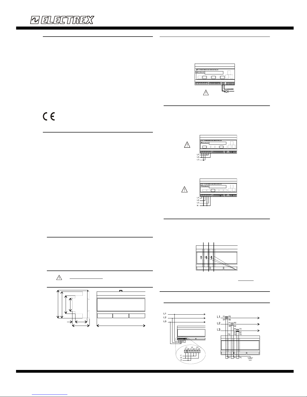
Fig. 1
Fig. 2
Fig. 3
Fig. 4
P1 P1 P1
Wire passages
3 POWER SUPPLY
The instrument must have a power supply with voltage ranging from 200 ÷ 240 VAC 50/60 Hz
(100 ÷ 120 VAC 50/60 Hz is also available on request) using max. cable gauge 4 mm2 and
attached to the power supply terminals (see Fig.1).
The instrument’s power supply does not need an earth connection.
The instrument requires the installation of an external 50 mA type HBC fuse in the power supply
circuit.
3.1 VOLTAGE MEASUREMENT CONNECTIONS
For the voltage measurement connection use wires with max gauge 4mm2. Insert the wires in
the screw terminals for the voltage measurement connection.
3.1.1 3 wires delta connection (? )
The diagram in Fig.2 indicate how to connect the terminals to the phases on unbalanced threephase systems without neutral (DELTA).
3.1.2 4 wires STAR CONNECTION (Y )
The diagrams in Fig. 3 indicate how to connect the terminals to the phases on unbalanced threephase systems with neutral (STAR).
The detailed wiring diagrams to the network are given in chapter 3.
3.2 CURRENT MEASUREMENT CONNECTIONS
The instrument is equipped with three wire passages through which the current wires must be
passed without having to interrupt them. Insert the wires as indicated in Fig.4 (instructions as
to how to insert the current wire are also found on the instrument’s label in correspondence with
the wire passages). The P1 and P2 indications identify the correct direction of the current.
Wires with max. 7 mm external diameter are permitted.
Advanced Function: If the instrument has been programmed for Cogeneration functioning, it
is absolutely essential that the sense (orientation) of the current direction be observed.
4 WIRING DIAGRAMS
4.1 CONNECTION ON UNBALANCED THREE-PHASE 3 WIRE DELTA
NETWORKS (?)
Voltage Signal Connection
Corrent Signal Connection
Fig. 5
Fig. 6
English
Instructions
9
5
90
62
41
10
58
45
157,5
Page 2
ELECTREX S.r.l. via Claudia, 96 - 41096 Savignano s/P (MO) - Italy - Tel. +39.59.796372 Fax. +39.59.796378
SUBJECT TO CHANGE WITHOUT NOTICE 02/2004
KILO
KILO M
Fig. 10
Fig. 9
Fig. 12
Fig. 11
Fig. 13
Fig. 14
C 1 2
C = Common
1 = Meter 1
2 = Meter 2
Min Pulse 5 mSec.
INSTRUMENT
INTERIOR
INSTRUMENT
ESTERIOR
Connection to voltage-free
contacts
Connection to open-collector transistor
4.4 ALARMS CONNECTION
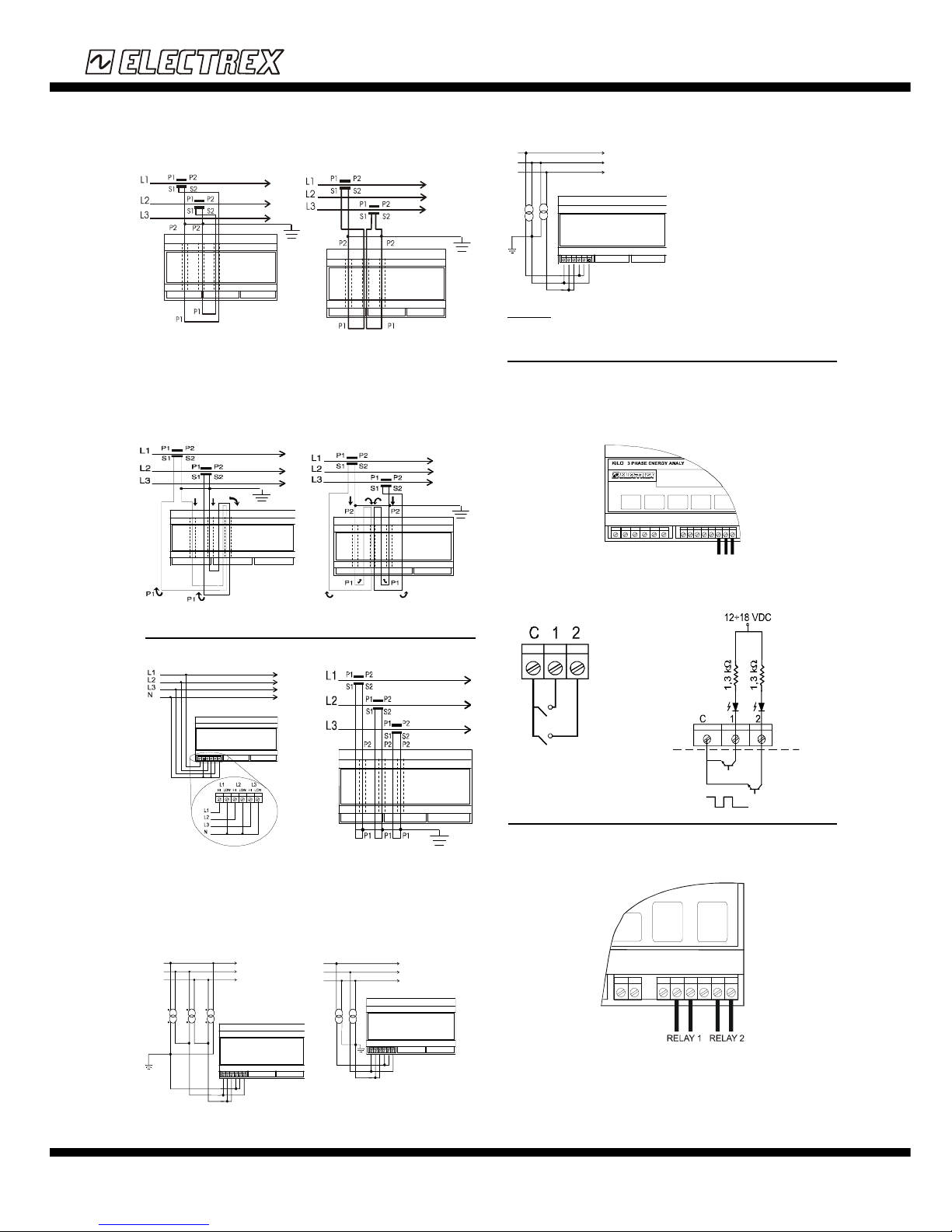
There are two alarms which drive two relays, the terminals are internally connected to
noramlly open voltage free contacts of an opto-mos (solid state relay) rating 250 VDC, 100mA.
Use cables with max. gauge 4 mm2 for the terminal connections (see Fig. 15).
C = Common
NO = Normally Open
C NO C NO
Fig. 15
Fig. 7-1
Fig. 7-2
Fig. 8-1
Fig. 8-2
Current signal connection
with 2 CTs (L1 and L2)
Current signal connection
with 2 CTs (L1 and L3)
Connection of 2 CTs in Cogeneration mode
The drawing in Fig. 6 indicates how to make the current connections with 3 CTs. The Fig. 71 and 7-2 indicate how to connect current signal using 2 CTs (Phase L1 and L2 or Phase L1
and L3).
CAUTION: In case of connection of 2 CTs it is absolutely essential to respect the sense
(orientation) of the CTs current output as indicated in the drawings (Fig. 7-1 and 7-2).
Advanced Functions: If the instrument has been programmed for Cogeneration mode,
connection of the CTs must be carried out as indicated in the drawings in Fig.10-1 and Fig.102 located on the next page.
4.2 CONNECTION ON UNBALANCED THREE-PHASE 4 WIRE NETWORKS
The drawing in Fig.10 indicates how to make the current connections with 3 CTs.
4.2.1 HIGH VOLTAGE THREE PHASE WIRES DELTA NETWROK WITH CT's
AND VT's
L
1
L3
L2
L1
L2
L3
L
1
L3
L2
L1
L2
L3
L
1
L3
L2
L1
L2
L3
WARNING: In Fig. 12 and 13 any one of the delta vertices may be earthed.
For the connection of CTs in medium or high voltage networks, follow the same procedure
described for low voltage connections.
4.3 CONNECTION OF THE AUXILIARY METERS
The instrument has two digital inputs to which two external meters can be connected (for
example, a water meter and a gas meter).
The digital inputs are optoisolated and internally power supplied (12 ÷ 18 VDC 1,3 KOhm)
and can count pulses with a maximum frequency of 100 Hz.
The connection must be carried out using cables with max. gauge 4 mm2 to be inserted in the
terminals indicated below in Fig.14.
Voltage signal connection with 3 VTs Voltage signal connection with 2 VTs
Voltage signal connection with 2 VTs
English
Instructions
Voltage signal connection
Current signal connection
Page 3
ELECTREX S.r.l. via Claudia, 96 - 41096 Savignano s/P (MO) - Italy - Tel. +39.59.796372 Fax. +39.59.796378
SUBJECT TO CHANGE WITHOUT NOTICE 02/2004
KILO
KILO M
Shield A B
(sheath) + -
Fig. 16
6 KEYBOARD DESCRIPTION
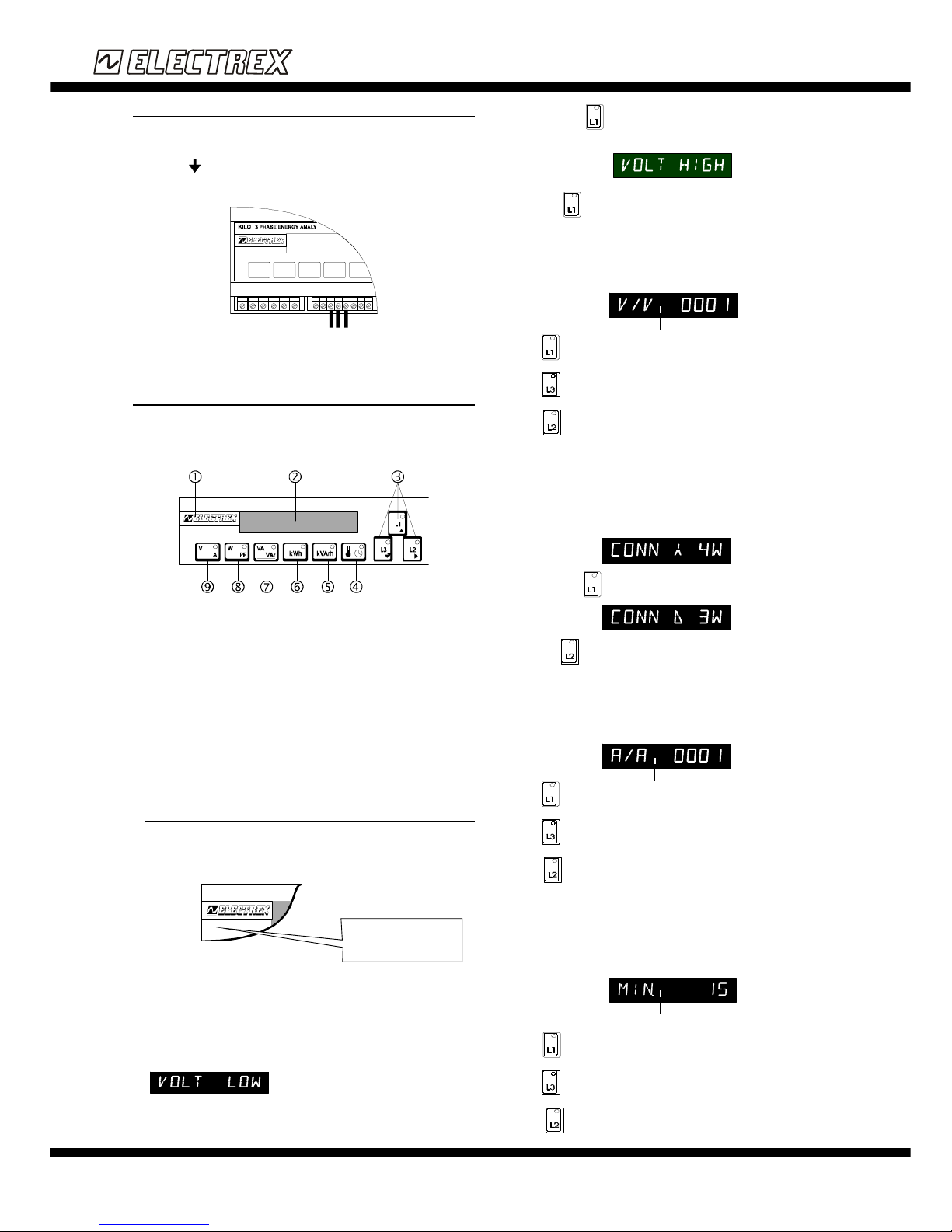
Instrument programming can be carried out on the keyboard located on the instrument’s front
panel. The keys for displaying the measurements, consumptions, temperature and the clock calendar
each have a green LED which lights up when that function is utilised. The L1, L2 and L3 keys each
have a red LED which lights up when that function (display of the phase measurements) is utilised.
KILO
3 PHASE ENERGY ANALYZER/CONTROLLER
? Key for access to programming and reset
? High luminosity display (adjustable)
? Key for phase selection (cursor keys during programming)
? Key for displaying the calendar/clock and the temperature
? Key for displaying the consumption of Three-phase Reactive Energy (kVArh) and of the
auxiliary contacts
? Key for displaying the consumption of Three-phase Active Energy (kWh)
? Key for displaying Three-phase instantaneous, average and peak Apparent Power
(VA)measurements and the three-phase instantaneous Reactive Power (VAr)
? Key for displaying three-phase instantaneous, average and peak Active Power (W)
measurement and Power Factor (Cos f)
? Key for Voltage and Current display
6.1 MEASUREMENT RELATED FUNCTION PROGRAMMING
The writing “ELECTREX” appears when the instrument is powered. After a few seconds the
voltage and current measurements will be displayed (the LED on the key is lighted). To enter
into programming mode, press simultaneously the programming access key (see Fig.18) and
the key.
KILO
3 PHASE ENERGY
The default settings provide:
- Low voltage measurement
- 4-wire connection (STAR)
- CT ratio = 1
- Integration time = 15 minutes
6.1.1 measurement functions SELECTION
The instrument can carry out measurements on both low and high voltage. The display will
show the first selection (direct measurements in low voltage):
By pressing the key the second selection will be displayed (measurements in high
voltage with VTs):
Press the key on the page selected and proceed to program the other functions.
6.1.2 VT TRANSFERTION RATIO MEASUREMENTS HIGH VOLTAGE
SELECTION
Select “VOLT HIGH” to access the programming page which enables the setting of the
transformation ratio of the VT utilised. The display will show:
The key increases the digit to be set (flashing).
The key decreases the digit to be set (flashing).
The key enables moving from one digit to another (from the more significant digit to
the less significant digit). Once the last digit is set, this key enables programming of the
transformation ratio of the VT and access to the next programming page.
6.1.3 CONNECTION TYPE SELECTION (STAR OR DELTA)
Selecting“VOLT LOW” on the first programming page or after setting the VT ratio, (having
selected “VOLT HIGH” on the first measurement page) select the type of connection. The
instrument can be connected to 4-wire networks (CONN 4W) or three wire networks (CONN
D 3W). The display will show:
By pressing the key the second selection will be displayed:
Press the key on the page which contains the connection wanted and proceed to the
programming of the other functions.
6.1.4 CT TRANSFERTION RATIO SELECTION
After selecting the type of connection (star or delta) the CT transformation programming page
appears. The display will show:
The key increases the digit to be set (flashing).
The key decreases the digit to be set (flashing).
The key enables moving from one digit to another (from the more significant digit to
the less significant digit). Onced the last digit is set, this key enables programming of the CT
transformation ratio and access to the next programming page.
6.1.5 AVERAGE POWERS INTEGRATION TIME SELECTION
The last programming page enables the setting of the integration time (in minutes) on which
the averages of Active Power and Apparent Power will be calculated. The display will show:
The key increases the digit to be set (flashing).
The key decreases the digit to be set (flashing).
The key enables moving from one digit to another (from the more significant digit
The key for access to
prgramming is located under
the writing "ELECTREX"
between the letters E and L
5 RS485 CONNECTION
The instrument has three terminals for connection to the RS485 port. The connection must be
carried out using a twisted pair inserted in the appropriate screw terminals (see Fig. 16). The
terminals marked "A" and "B" indicate the polarity of the contacts. There is also a terminal identified
by the symbol for connecting the shield (sheath) of the twisted pair to be used for network
installation in high interference environments or in the presence of strong currents. The polarity of
the contacts must be observed when the connection is made (see also the indications on the label).
It is recommended to use a twisted pair cable with minimum section of 0,36 mm2 (22 AWG)
characteristic impedence 120W and with capacity lower than 60 pF/m.
Flashing digit
Flashing digit
Flashing digit
English
Instructions
Page 4
ELECTREX S.r.l. via Claudia, 96 - 41096 Savignano s/P (MO) - Italy - Tel. +39.59.796372 Fax. +39.59.796378
SUBJECT TO CHANGE WITHOUT NOTICE 02/2004
KILO
KILO M
to the less significant digit). Once the last digit is set, it enables confirmation of the programming
of the integration time of the averages and to exit from programming.
6.2 SERIAL PORT AND THE CLOCK/CALENDAR PROGRAMMING
Simultaneously press the key and the programming enabling key to program the
serial, the date and the time.
6.2.1 TRANSMISSION SPEED SELECTION
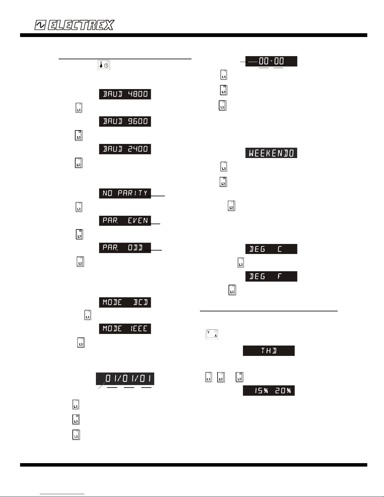
The transmission speed is the first selection to be made. By default on the display will appear:
Press the key to display:
Press the key to display
Press the key to confirm it and continue programming.
6.2.2 PARITY TYPE SELECTION
Parity type is the second selection to be carried out. By default will be displayed:
Press the key to display:
Press the key to display:
Press the key on the page selected to confirm the selection and continue with
programming.
6.2.3 TRASMISSION MODE SELECTION
The last specification of the serial to be set is the transmission mode. By default the following
is displayed:
By pressing the key the second selection possibility is displayed:
Press the key on the page selected to confirm the selection and proceed to
programming the other functions.
6.2.4 DATE SETTING
After programming the serial port, it access the date setting page. The display will show:
The key increases the digit to be set (flashing).
The key decreases the digit to be set (flashing)
The key enables moving from one digit to another (from left to right). Once the last digit
is set, it enables confirmation of the programming and to access to the time programming page.
6.2.5 TIME SETTING
After confirming the date, it accesses the time setting page. The display will show:
The key increases the digit to be set (flashing).
The key decreases the digit to be set (flashing).
The key enables moving from one digit to another (from left to right). Once the last digit
is set, it enables confirmation of the programming and to access to the selection page of the
surveyed temperature measurement unit.
6.2.6 WEEK DAY SETTING
This function is available on KILO-M only ad it is fundamental for recording in memory the
weekly consumtion. The data are stored in memory at 24:00 hours of each Sunday. The
display will show the default setting:
The key increases the digit to be set (flashing).
The key decreases the digit to be set (flashing). The correspondence between the
number and the day of the week is as follows:
0= Monday;1=Tuesday; 2=Wednesday; 3=Thursday; 4=Friday; 5=Saturday; 6= Sunday
Press the key in the page relative to the selection to confirm and then proceed to
programming the other functions.
6.2.7 TEMPERATURE MEASUREMENT SELECTION UNIT (KILO-M)
The measurement of the ambient temperature by an internal sensor is supplied either in Celsius
(C) or in Farenheit (F). After setting the date and time it accesses the page for selecting the
temperature measurement unit. On the display will appear:
By pressing the key the second selection will be displayed:
Press the key on one of these two pages to select the one wanted and return to
measurement mode.
7 HARMONIC DISTORSION
A new additional function, called THD, has been implemented on all the instruments (T). This
funzion can be displayed on every phase. Such measurement represents the total harmonic distortion
on Voltage and Current for each single phase. When the instrument is switched on, the led of the
key is ON which represents the three-phase Voltage and Current measurement page. If
the key is pressed again, the following is displayed:
If each of the three phases is pressed, the percentage representing the total harmonic phase
distorsion on Voltage and Current will be displayed.
If , and keys are pressed, the following page will be displayed :
No parity
Parity Even
Parity Odd
YEAR MONTH DAY
Flashing
digit
MINUTES
HOUR
Flashing
digit
English
Instructions
 Loading...