

Electrex x3m-D, Flash-D Installation Manual
1
X3M-D
FLASH-D
Energy data manager
&
Electric Energy Analyzer
Installation Manual
Unless specifically itemized, this instructions manual is common
to both the instruments type X3M-D and Flash-D.
Version 5 dated June 20th 2005 (PRELIMINARY VERSION)
The document can be modified without prior information.

2
Index
INTRODUCTION .............................................................................................................................. 3
1.1 COPYRIGHT........................................................................................................................ 3
1.2 WARRANTY ........................................................................................................................3
1.3 RETURN AND REPAIR FORMALITIES .............................................................................. 3
1.3.1 RE-SHIPPING OF REPAIRED PRODUCT.................................................................. 3
1.3.2 Return Material Authorization (RMA form) ................................................................... 4
2 Safety......................................................................................................................................... 5
2.1 Operator safety .................................................................................................................... 5
3 Mounting .................................................................................................................................... 6
3.1 Instruments size (mm) ......................................................................................................... 6
3.2 Optional modules size (mm) ................................................................................................ 6
3.3 Fixing and blocking .............................................................................................................. 6
4 Wiring diagrams......................................................................................................................... 7
4.1 Power supply ....................................................................................................................... 7
4.2 Measurement connections................................................................................................... 7
4.2.1 Voltage connection........................................................................................................ 7
4.2.2 Current connection........................................................................................................ 7
4.2.3 4W Star connection (4 wire).......................................................................................... 8
4.2.4 3W Delta connection (3 wire) ........................................................................................ 9
4.2.4.1 Connection with 2 CTs on L1 and L3 ................................................................... 9
4.2.4.2 Connection with 2 CTs on L1 and L2 ................................................................. 10
4.2.5 2 Wire connection (single phase)................................................................................ 10
4.2.6 2 Wire connection (bi-phase) ...................................................................................... 11
4.3 Outputs connection............................................................................................................ 11
4.4 Optional modules connection............................................................................................. 12
4.4.1 RS485 Option.............................................................................................................. 12
4.4.2 RS232 Option.............................................................................................................. 13
4.4.3 Dual 4-20 mA analog output option............................................................................. 13
5 Instrument use ......................................................................................................................... 14
5.1 Instrument set up ...............................................................................................................14
5.1.1 Set up sequence ......................................................................................................... 15
5.1.2 Configuration procedure.............................................................................................. 16
5.1.2.1 Electrical system configuration........................................................................... 16
5.1.2.2 Communication characteristics configuration..................................................... 18
5.1.2.3 Digital Outputs configuration .............................................................................. 18
5.1.2.4 Pulse characteristics configuration..................................................................... 19
5.1.2.5 Alarm configuration ............................................................................................ 20
5.1.2.6 4-20 mA Analog Outputs configuration. ............................................................. 22
5.1.2.6.1 Alarms and 4-20 mA output configuration for the average (AVG) parameters .............. 23
5.1.2.7 Clock calendar configuration (for X3M-D only) .................................................. 24
5.1.2.8 Contrast adjustment ........................................................................................... 25
5.1.2.8.1 Time zones ..................................................................................................................... 26
5.1.3 Reset Procedure ......................................................................................................... 30
5.2 Readings............................................................................................................................ 31
5.2.1 Readings selection keys.............................................................................................. 31
5.2.1.1 Voltage and Frequency readings ....................................................................... 31
5.2.1.2 Current readings ................................................................................................ 31
5.2.1.3 Powers ............................................................................................................... 32
5.2.1.4 Power Factor...................................................................................................... 34
5.2.1.5 Energies ............................................................................................................. 34
5.2.1.6 Tariff Energies and Tariff Maximum Demand (for X3M-D only) ........................ 35
5.2.1.7 Calendar Clock (for X3M-D only) and Life Time................................................. 36

3
INTRODUCTION
We thank you for choosing an Electrex instrument
We invite you to carefully read this instructions manual for the best use of the X3M D and Flash D
instruments.
1.1 COPYRIGHT
Electrex S.r.l. All rights are reserved.
It is forbidden to duplicate, adapt, transcript this document without Electrex written authorization, except
when regulated accordingly by the Copyright Laws.
Copyright© 2003-2004
1.2 WARRANTY
This product is covered by a warranty against material and manufacturing defects for a period of 36 months
period from the manufacturing date
The warranty does not cover the defects that are due to:
• Negligent and improper use
• Failures caused by atmospheric hazards
• Acts of vandalism
• Wear out of materials
Electrex reserves the right, at its discretion, to repair or substitute the faulty products
The warranty is not applicable to the products that will result defective in consequence of a negligent and
improper use or an operating procedure not contemplated in this manual.
1.3 RETURN AND REPAIR FORMALITIES
Electrex accepts the return of instruments for repair only when authorized in advance. For instrument
purchased directly, the repair authorization must be requested to Electrex directly by using the enclosed
RMA form. We recommend otherwise to contact your local distributor for assistance on the return/repair
formalities. In both the cases, the following information must be supplied:
• Company full data
• Contact name for further communication
• Product description
• Serial number
• Description of the returned accessories
• Invoice / Shipping document number and date
• Detailed description of the fault and of the operating condition when the fault occurred
The Electrex repair lab will send the authorization number to the customer directly or to the distributor as per
applicable case.
The RMA authorization number shall be clearly marked on the packaging and on the return transport
document.
WARNING: Failure to indicate the RMA number on the external packaging will entitle our warehouse to
refuse the delivery upon arrival and to return the parcel at sender’s charge.
The material must be shipped:
- within 15 working days from the receipt of the return authorization number
- free destination i.e. all transport expenses at sender’s charge.
- to the following address: Electrex S.r.l.
Via Claudia 96 - 41056 Savignano s/P (MO) - Italy
Atn. Repair laboratory
- the units covered by warranty must be returned in their original packaging.
1.3.1 RE-SHIPPING OF REPAIRED PRODUCT
The terms for re-shipment of repaired products are ex-works, i.e. the transport costs are at customer charge.
Products returned as detective but found to be perfectly working by our laboratories, will be charged a fixed
fee (40.00 Euro + VAT where applicable) to account for checking and testing time irrespective of the
warranty terms.
4
1.3.2 Return Material Authorization (RMA form)
Request for the authorization number for the return of goods
Date:
Company:
Contact name:
TEL: FAX:
Product description:
Serial number:
Description of the returned accessories (if any):
Original purchase Invoice (or Shipping document) number and date.
NB: The proof of purchase must be provided by the customer. Failure to complete this area will automatically void all warranty.
Detailed description of the malfunction and of the operating conditions when the fault occurred
Tick off for a quotation
Should a product be found by our laboratories to be perfectly working, a fixed amount of 40 Euro (+VAT if applicable) will be charged to
account for checking and testing time irrespective of the warranty tems.
Space reserved to ELECTREX
R.M.A. No.
The RMA number shall be clearly indicated on the external packaging and on the shipping document:. Failure to observe this
requirement will entitle the ELECTREX warehouse to refuse the delivery.

5
2 Safety
This instrument was manufactured and tested in compliance with IEC 1010 class 2 standards and in
accordance with VDE 0110 group B insulation standards for operating voltages up to 250 VAC rms phase to
neutral.
In order to maintain this condition and to ensure safe operation, the user must comply with the indications
and markings contained in the following instructions:
• When the instrument is received, before starting its installation, check that it is intact and no damage
occurred during transport.
• Before mounting, ensure that the instrument operating voltages and the mains voltage are
compatible then proceed with the installation.
• The instrument power supply needs no earth connection.
• The instrument is not equipped with a power supply fuse; a suitable external protection fuse must be
foreseen by the contractor.
• Maintenance and/or repair must be carried out only by qualified, authorized personnel
• If there is ever the suspicion that safe operation is no longer possible, the instrument must be taken
out of service and precautions taken against its accidental use.
• Operation is no longer safe when:
1) There is clearly visible damage.
2) The instrument no longer functions.
3) After lengthy storage in unfavorable conditions.
4) After serious damage occurred during transport
The instruments X3M-D and Flash-D must be installed in respect of all the local regulations.
2.1 Operator safety
Warning: Failure to observe the following instructions may lead to a serious danger of death.
- During normal operation dangerous voltages can occur on instrument terminals and on
voltage and current transformers. Energized voltage and current transformers may generate
lethal voltages. Follow carefully the standard safety precautions while carrying out any
installation or service operation.
- The terminals of the instrument must not be accessible by the user after the installation. The
user should only be allowed to access the instrument front panel where the display is
located.
- Do not use the digital outputs for protection functions nor for power limitation functions. The
instrument is suitable only for secondary protection functions.
- The instrument must be protected by a breaking device capable of interrupting both the
power supply and the measurement terminals. It must be easily reachable by the operator
and well identified as instrument cut-off device.
- The instrument and its connections must be carefully protected against short-circuit.
Precautions: Failure to respect the following instructions may irreversibly damage to the instrument.
- The instrument is equipped with PTC current limiting device but a suitable external
protection fuse should be foreseen by the contractor.
- The outputs and the options operate at low voltage level; they cannot be powered by any
unspecified external voltage.
- The application of currents not compatible with the current inputs levels will damage to the
instrument.

6
3 Mounting
3.1 Instruments size (mm)
6 DIN rail modules
3.2 Optional modules size (mm)
2 DIN rail modules.
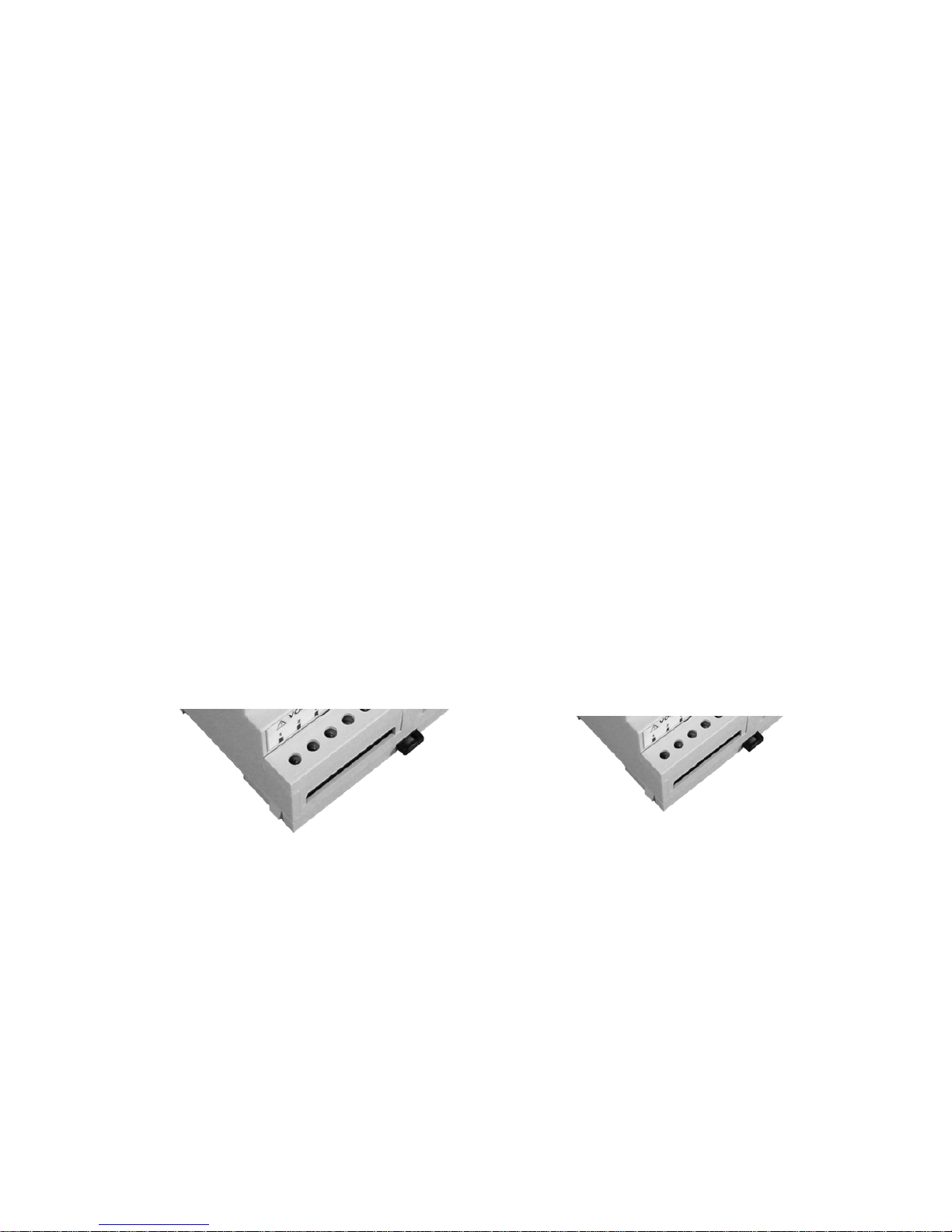
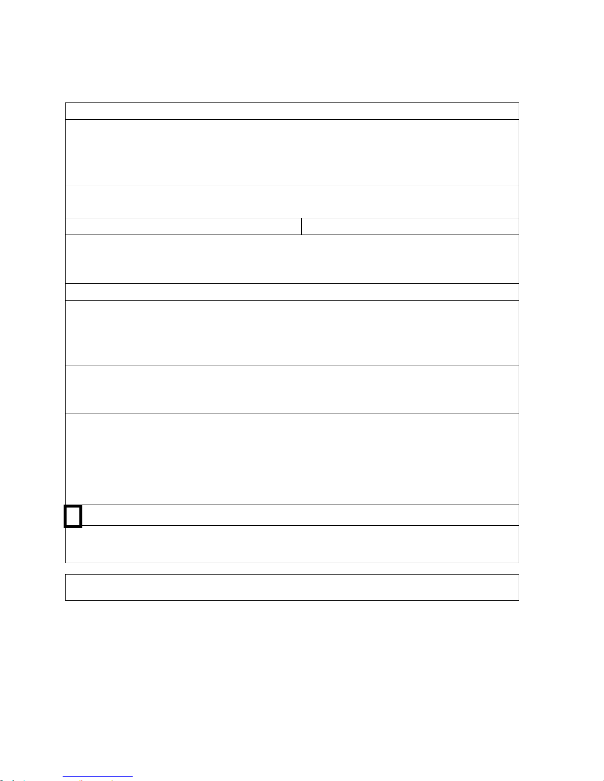
3.3 Fixing and blocking
The instrument (as well as the optional modules) are fixed to the DIN rail by means of the spring clip located
on the rear side of the unit

7
4 Wiring diagrams
4.1 Power supply
The instrument is fitted with a separate power supply with extended operating
range. The power supply terminals are numbered (10) and (11).
Use cables with max cross-section of 2,5 mm
2
.
4.2 Measurement connections
4.2.1 Voltage connection
Use cables with max cross-section of 2,5 mm2 and connect them to the terminals marked VOLTAGE INPUT
on the instrument according to the applicable diagrams that follow.
4.2.2 Current connection
It is necessary to use external CTs with a primary rating adequate to the load to be metered and with a 5A
secondary rating. The number of CTs to be used (1, 2 or 3) depends upon the type of network.
Connect the CT output(s) to the terminals marked CURRENT INPUT of the instrument according to the
applicable diagrams that follow.
Use cables with cross-section adequate to the VA rating of the CT and to the distance to be covered. The
max cross-section for the terminals is 2,5 mm
2
.
N.B. The CT secondary must always be in short circuit when not connected to the instrument in order to
avoid damages and risks for the operator.
Warning: THE PHASE RELATIONSHIP AMONG VOLTAGE AND CURRENT SIGNALS MUST BE
CAREFULLY RESPECTED. ALL DISREGARD OF THIS RULE OR OF THE WIRING
DIAGRAM LEADS TO SEVERE MEASUREMENT ERRORS.

8
4.2.3 4W Star connection (4 wire)
Low voltage 3 CTs High voltage 3 PTs 3 CTs
Configuration 3P 4W Configuration 3P 4W
Low Voltage 1 CT (symmetrical and balanced load)
Configuration 3P-b 4W

9
4.2.4 3W Delta connection (3 wire)
Connection with 3 CTs Connection with 1 CT
Low Voltage 3 CTs (unbalanced load) Low Voltage 1 CT (symmetrical and balanced
load)
Configuration 3P 3W Configuration 3P-b 3W
4.2.4.1 Connection with 2 CTs on L1 and L3
Low Voltage 2 CTs High Voltage 2 PTs 2 CTs
Configuration 3P 3W Configuration 3P 3W

10
4.2.4.2 Connection with 2 CTs on L1 and L2
Low Voltage 2 CTs High Voltage 2 PTs 2 CTs
Configuration 3P 3W Configuration 3P 3W
4.2.5 2 Wire connection (single phase)
Low Voltage (phase-neutral) 1 CT
Configuration 1P 2W

11
4.2.6 2 Wire connection (bi-phase)
Low Voltage (phase-phase) 1 CT
Configuration 2P 2W
4.3 Outputs connection
The instrument is equipped with two opto-isolated transistor outputs rated 27 Vdc, 27 mA (DIN 43864
standards).
The outputs working mode is set by default to operate as pulse output proportional to the Active energy
(output 1) and to the Reactive energy (output 2). They support an output rate of 1.000 pulses per kWh (or
kvarh) referred to the instrument input range without any CT and PT multiplier.
In order to calculate the energy value of each pulse the following formula must be considered.
kWhPulse
KK
K
PTCT
P
/
×
=
Where: K
p
= energy of each pulse; KCT = CT ratio ; K
PT
= PT ratio ;
Pulse/kWh = Pulse rate
Example: CT = 100/5; PT = 20.000/100
pulsekWhK
P
/4
1000
20020
=
×
= or kWh = Pulse count / 4
Other pulse rate settings may be however programmed as described in the instrument set up section.
The operating mode of the digital outputs may also be changed to work as alarm output or as remote output
device controlled by the Modbus protocol as described in the instrument set up section.

12
4.4 Optional modules connection
The optional modules shall be placed beside of the instrument and shall be connected to the same by
means of the cable supplied with.
The optional modules are self-supplied; the instrument recognises the type of option(s) connected and the
applicable programming menu will automatically appear when necessary.
CN1 connector: suitable for the RS485 or RS232 optional modules
CN2 connector: suitable for the 4-20 mA optional module or for the Hardware up-date key
4.4.1 RS485 Option
RS485 pin out
1
A +
2
B -
3
Shield
 Loading...