

Electrex Femto D4, FEMTO D4 70A, FEMTO 96 Installation Manual
FEMTO D4
INSTALLATION GUIDE
COPYRIGHT
Electrex is a trademark of Akse S.r.l. All rights reserved.
It is forbidden to duplicate, adapt, transcript this document without Akse written authorization,
except when regulated accordingly by the Copyright Laws.
WARRANTY
This product is covered by a warranty against material and manufacturing defects for a 24
months period from the manufacturing date.
The warranty does not cover the defects that are due to:
• Negligent and improper use
• Failures caused by atmospheric hazards
• Acts of vandalism
• Wear out of materials
• Firmware upgrades
Akse reserves the right, at its discretion, to repair or substitute the faulty products
The warranty is not applicable to the products that will result defective in consequence of a
negligent and improper use or an operating procedure not contemplated in this manual.
RETURN AND REPAIR FORMALITIES
Akse accepts the return of instruments for repair only when authorized in advance. The
transport costs are at customer charge.
RE-SHIPPING OF REPAIRED PRODUCT
The terms for re-shipment of repaired products are ex-works, i.e. the transport costs are
at customer charge.
Products returned as detective but found to be perfectly working by our laboratories, will
be charged a fl at fee to account for checking and testing time irrespective of the warranty
terms.
SAFETY
This instrument was manufactured and tested in compliance with CEI EN 61010-1 CAT
III -300V, class 2, standards for operating voltages up to 300 VAC rms phase to neutral.
In order to maintain this condition and to ensure safe operation, the user must comply with
the indications and markings contained in the following instructions:
• When the instrument is received, before starting its installation, check that it is
intact and no damage occurred during transport.
• Before mounting, ensure that the instrument operating voltages and the mains
voltage are compatible then proceed with the installation.
• The instrument power supply needs no earth connection.
• The instrument is not equipped with a power supply fuse; a suitable external
!
protection fuse must be foreseen by the contractor.
• Maintenance and/or repair must be carried out only by qualifi ed, authorized
personnel
• If there is ever the suspicion that safe operation is no longer possible, the instrument
must be taken out of service and precautions taken against its accidental use.
• Operation is no longer safe when:
1) There is clearly visible damage.
2) The instrument no longer functions.
3) After lengthy storage in unfavorable conditions.
4) After serious damage occurred during transport
The instruments must be installed in respect of all the local regulations.
OPERATOR SAFETY
Warning: Failure to observe the following instructions may lead to a serious danger of
death.
• During normal operation dangerous voltages can occur on instrument terminals and
on voltage and current transformers. Energized voltage and current transformers
may generate lethal voltages. Follow carefully the standard safety precautions while
carrying out any installation or service operation.
• The terminals of the instrument must not be accessible by the user after the installation.
The user should only be allowed to access the instrument front panel where the
display is located.
• Do not use the digital outputs for protection functions nor for power limitation functions.
The instrument is suitable only for secondary protection functions.
• The instrument must be protected by a breaking device capable of interrupting both
the power supply and the measurement terminals. It must be easily reachable by the
operator and well identifi ed as instrument cut-off device.
• The instrument and its connections must be carefully protected against short-circuit.
Precautions: Failure to respect the following instructions may irreversibly damage to the
instrument.
• The outputs and the options operate at low voltage level; they cannot be powered by
any unspecifi ed external voltage.
• The application of currents not compatible with the current inputs levels will damage
to the instrument.
Further documentation may be downloaded from our web site www.electrex.it.
This document is owned by company AKSE that reserves all rights.
DECLARATION OF CONFORMITY
Akse hereby declares that its range of products complies with the following directives EMC
89/336/EEC 73/23CE 93/68 CE and complies with the following product’s standard CEI
CEI EN 61326 – IEC 61326 CEI EN 61010 – IEC 61010
The product has been tested in the typical wiring confi guration and with peripherals
conforming to the EMC directive and the LV directive.
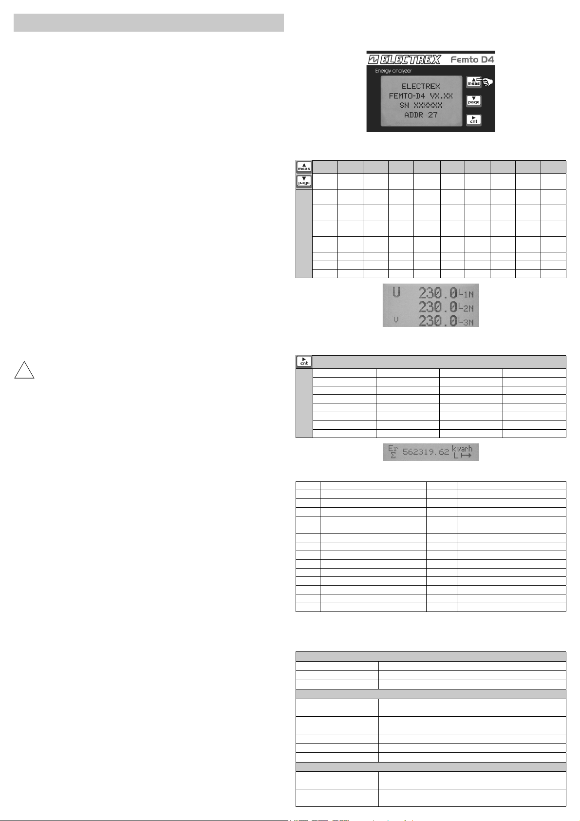
READINGS
Keep pressed for 2
seconds to display:
- Type of instrument
- Firmware version
- Serial number
- RS485 address
READINGS DISPLAYED IN THE UPPER SCREEN AREA
(The parameters available vary according to instrument confi guration)
Ea Er Es U U-f I P Q S PF
Ea Imp Er Ind
Ea Exp Er Cap
Ea
Phase
Press to scroll readings
READINGS DISPLAYED IN THE LOWER SCREEN AREA
(The parameters available vary according to instrument confi guration)
Ea ∑+ Er L ∑+ Er C ∑+ Es ∑+
Ea ∑- Er L ∑- Er C ∑- Es ∑-
Ea P+ Er L P+ Er C P+ Es P+
Ea P- Er L P- Er C P- Es P-
CNT1 ∑
CNT1 P
TIME ∑ TIME P
Press for 2 seconds
TEMP °C TEMP °F
LEGEND OF PARAMETERS AND SYMBOLS
L-N Phase Neutral U Voltage
L-L Phase Phase I Current
THD Total Harmonic Distortion In Neutral current
Avg Average (rolling) value P Active Power
MD Maximum Demand Q Reactive Power
Imp (+) Import value S Apparent Power
Exp (-) Export value PF Power Factor
IND Inductive Ea Active Energy
CAP Capacitive Er Reactive Energy
Min Minimum values (10 cycles time base) Es Apparent Energy
Max Maximum values (10 cycles time base) f Frequency
TIME ∑ Life Time (total) TEMP °C Temperature in °Celsius
TIME P Life Time (partial) TEMP °F Temperature in °Fahrenheit
CNT ∑ Pulse count (total)
CNT P Pulse count (partial)
MECHANICAL CHARACTERISTICS
Case Self-extinguishing plastic material class V0
Protection degree IP40 on front panel
Size 70 x 90 x 58 mm (4 DIN modules)
CURRENT INPUT
Direct Up to 300 Vrms phase-neutral
With external PT(VT) Primary: programmable (max. 400 kV)
Power supply 230/240Vac +/- 10% 50/60Hz
Self consumption < 3VA
MODELS
PFA6411-02 FEMTO D4 RS485 230-240V
PFA6411-12 FEMTO D4 RS485 230-240V 1DI 2DO
Es Imp L-N L-N
Imp
Es Exp L-L L-LfIn P Avg
Imp
Er Ind
Exp
Er Cap
Exp
Er Ind
Phase
THD
L-N
THD L-L THD L-LfI Max P MD
Min L-N Min L-N I Avg P MD
Min L-L Min L-L I MD
Max L-N Max L-N
Max L-L Max L-L
f
THD L-NfTHD P Avg
Press to change readings
or 519 Vrms phase to phase
Secondary: programmable (max. 300 V)
Overload: 900 Vrms phase to phase for 1 sec
ENERGY ANALYZER
ENERGY ANALYZER
IPQSPF
Q Avg
Imp
Imp
Q Avg
Exp
Exp
Q MD
Imp
Imp
Q MD
Exp
Exp
S Avg
Imp
S Avg
Exp
S MD
Imp
S MD
Exp
DEVICE SETUP
OPERATING KEYS
Click Change selected fi eld
value
Click
Go to next window Back to initial entry fi eld Exits setup
2 sec
ENTERS INTO SET UP MODE
(Push together for 2 seconds)
Change selected fi eld value Go to next fi eld
SETUP SEQUENCE
PAGE PARAMETERS VALUES AVAILABLE DEFAULT
PASSWORD REQUEST 0000 ... 9999 0000
RS485
RS485 Address 1 ... 247 27
Rate 2400, 4800, 9600, 19200, 38400 38400
Data Bit 7 or 8 8
Parity N = no parity, E =even parity, O = odd parity N
Stop Bit 1 or 2 2
RS-485
ADDR 027
COM 38400-8-N-2
S.T.
NETWORK
Type (note n.1) 3PH-3W-2CT, 3PH-4W, 2PH-2W, 1PH-2W 3PH-4W
Export NO, YES NO
CT 10000/1 or 5 5/5
VT 400000/300 1/1
100
NETWORK
TYPE 3PH-4W
EXPORT NO
CT 00005/5
VT 000001/001
AVG-MD TIME (note n.2)
POWERS 1...60 (minutes) 15
CURRENTS 1...60 (minutes) 8
AVG-MD TIME
POWERS 15
CURRENTS 08
ALARM 1 / A (note n.11)
MODE (note n.3) Normal, 1-OF-3, 3-OF-3, DERIV, UNBAL NORMAL
TYPE (note n.4) MAX, MIN MIN
MEAS (note n.5)
THRE (note n.5) Threshold value 0
Controlled measure. See table n.1 for register
selection
ALARM 1/A
MODE NORMAL
TYPE MIN
MEAS 200
THRE 000.00
ALARM 1 / B
HYST 1...100 (%) 1
DELAY 1...99 (seconds) 1
AVG (note n.6) 1...99 (seconds) 1
OUT (note n.7) Normal, Hold, Pulse-L, Pulse-S NORMAL
ALARM 1/B
HYST 01
DELAY 01 S/01 S
AVG 01
OUT NORMAL
ALARM 2 / A (note n.11)
ALARM 2 / B
ALARM 3 / A (note n.11)
ALARM 3 / B
ALARM 4 / A (note n.11)
ALARM 4 / B
MODE (note n.3) Normal, 1-OF-3, 3-OF-3, DERIV, UNBAL NORMAL
TYPE (note n.4) MAX, MIN MIN
MEAS (note n.5)
THRE (note n.5) Threshold value 0
HYST 1...100 (%) 1
DELAY 1...99 (seconds) 1
AVG (note n.6) 1...99 (seconds) 1
OUT (note n.7) Normal, Hold, Pulse-L, Pulse-S NORMAL
MODE (note n.3) Normal, 1-OF-3, 3-OF-3, DERIV, UNBAL NORMAL
TYPE (note n.4) MAX, MIN MIN
MEAS (note n.5)
THRE (note n.5) Threshold value 0
HYST 1...100 (%) 1
DELAY 1...99 (seconds) 1
AVG (note n.6) 1...99 (seconds) 1
OUT (note n.7) Normal, Hold, Pulse-L, Pulse-S NORMAL
MODE (note n.3) Normal, 1-OF-3, 3-OF-3, DERIV, UNBAL NORMAL
TYPE (note n.4) MAX, MIN MIN
MEAS (note n.5)
THRE (note n.5) Threshold value 0
HYST 1...100 (%) 1
DELAY 1...99 (seconds) 1
AVG (note n.6) 1...99 (seconds) 1
OUT (note n.7) Normal, Hold, Pulse-L, Pulse-S NORMAL
Controlled measure. See table n.1 for register
selection
Controlled measure. See table n.1 for register
selection
Controlled measure. See table n.1 for register
selection
DISPLAY
DIGITAL OUT 1 (note n.8)
CONTRAST 20 - 45 28
MODE PULSE, ALARM, REMOTE PULSE
POLARITY NO, NC NO
DIGITAL OUT 1
MODE PULSE
POLATITY NO
PULSE OUT 1
MEAS (note n.9)
PRIMARY (note n.10) YES, NO YES
WEIGHT 1...100000000 (Wh/100) 100000
WIDTH 50ms...1S 500
P-IMP, QL-IMP, QC-IMP, S-IMP, P-EXP,
QL-EXP, QC-EXP, S-EXP
PULSE OUT 1
MEAS P-IMP
PRIMARY YES
WEIGHT 100.00k
WIDTH 0500
DIGITAL OUT 2 (note n.8)
PULSE OUT 2
CLEAR TOTAL COUNTERS NO, YES NO
CLEAR PARTIAL COUNTERS NO, YES NO
CLEAR MIN-MAX NO, YES NO
CLEAR MAX DEMAND NO, YES NO
RESTORE FACTORY SETTINGS NO, YES NO
ENTER NEW PASSWORD 0000 ... 9999 0000
EXIT SETUP
(push for 2 seconds)
MODE PULSE, ALARM, REMOTE PULSE
POLARITY NO, NC NO
MEAS (note n.9)
PRIMARY (note n.10) YES, NO YES
WEIGHT 1...100000000 (Wh/100) 100000
WIDTH 50ms...1S 500
P-IMP, QL-IMP, QC-IMP, S-IMP, P-EXP,
QL-EXP, QC-EXP, S-EXP
TABLE n.1 (ModBus Registers for alarm confi guration)
REGISTER DESCRIPTION SYMBOL UNITS
200 Phase to Neutral Voltage, THD THD U1N [%]
202 Phase to Neutral Voltage, THD THD U2N [%]
204 Phase to Neutral Voltage, THD THD U3N [%]
206 Phase to Phase Voltage, THD THD U12 [%]
208 Phase to Phase Voltage, THD THD U23 [%]
210 Phase to Phase Voltage, THD THD U31 [%]
212 Phase Current, THD THD I1 [%]
200
214 Phase Current, THD THD I2 [%]
216 Phase Current, THD THD I3 [%]
218 Frequency of U1N f [Hz]
220 Phase to Neutral Voltage, RMS Amplitude U1N [V]
222 Phase to Neutral Voltage, RMS Amplitude U2N [V]
224 Phase to Neutral Voltage, RMS Amplitude U3N [V]
226 Phase to Phase Voltage, RMS Amplitude U12 [V]
228 Phase to Phase Voltage, RMS Amplitude U23 [V]
230 Phase to Phase Voltage, RMS Amplitude U31 [V]
232 Phase Current, RMS Amplitude I1 [A]
234 Phase Current, RMS Amplitude I2 [A]
236 Phase Current, RMS Amplitude I3 [A]
238 Neutral Current, RMS Amplitude IN [A]
240 Phase Active Power ( Imp/ Exp) P1 [W]
242 Phase Active Power ( Imp/ Exp) P2 [W]
244 Phase Active Power ( Imp/ Exp) P3 [W]
246 Phase Reactive Power ( Imp/ Exp) Q1 [var]
248 Phase Reactive Power ( Imp/ Exp) Q2 [var]
250 Phase Reactive Power ( Imp/ Exp) Q3 [var]
252 Phase Apparent Power S1 [VA]
254 Phase Apparent Power S2 [VA]
256 Phase Apparent Power S3 [VA]
258 Phase Power Factor ( Imp/ Exp) PF1 [-]
200
260 Phase Power Factor ( Imp/ Exp) PF2 [-]
262 Phase Power Factor ( Imp/ Exp) PF3 [-]
264 Phase to Neutral Voltage, Mean THD THD Ul [%]
266 Phase to Phase Voltage, Mean THD THD UD [%]
268 Phase Current, Mean THD THD I [%]
270 Phase to Neutral Voltage, Mean RMS Amplitude Ul [V]
272 Phase to Phase Voltage, Mean RMS Amplitude UD [V]
274 Three phase current, RMS Amplitude I [A]
276 Total active power ( Imp/ Exp) PS [W]
278 Total reactive power ( Imp/ Exp) QS [var]
200
280 Total apparent power SS [VA]
282 Total power factor ( Imp/ Exp) PFS [-]
332 Phase Current, RMS Amplitude, AVG I1 AVG [A]
334 Phase Current, RMS Amplitude, AVG I2 AVG [A]
336 Phase Current, RMS Amplitude, AVG I3 AVG [A]
344 Total imported active power, AVG P Imp AVG [W]
346 Total imported inductive power, AVG Qind Imp AVG [var]
348 Total imported capacitive power, AVG Qcap Imp AVG [var]
350 Total imported apparent power, AVG S Imp AVG [VA]
352 Total exported active power, AVG P Exp AVG [W]
200
354 Total exported inductive power, AVG Qind Exp AVG [var]
356 Total exported capacitive power, AVG Qcap Exp AVG [var]
358 Total exported apparent power, AVG S Exp AVG [VA]
376 External Pulse Counter, With Weight, Total counter
384 External Pulse Counter, With Weight, Partial
or Tariff T1
CNT1 S
CNT1 P
Counter or Tariff T2
P-IMP
QL-IMP
 Loading...