

Page 1
INSTALLATION GUIDE
EXA 96 - EXA NET 96
MECHANICAL CHARACTERISTICS
Case Self-extinguishing plastic material class V0
Protection degree IP40 on front panel, IP20 terminals side
Size 96 x 96 x 72 mm
VOLTAGE INPUT
Direct insertion Up to 300 Vrms phase-neutral or 520 Vrms phase to phase
With external VT: Primary: programmable (max. 400 kV)
Secondary: programmable (max. 300 V)
Overload: 900 Vrms phase to phase for 1 sec
Aux. power supply 85/265Vac +/- 10% 50/60Hz
Self consumption: < 2 watt
MODELS
PFNE9-117Q9-0M0 EXA RJ45 96 85-265V 2DI 2DO
ENERGY ANALYZER & DATA MANAGER
PFNE9-115Q9-110 EXA NET 96 WEB 85÷265V 2DI 2DO
ENERGY ANALYZER & WEB DATA MANAGER
COPYRIGHT
Electrex is a trademark of Akse S.r.l. All rights reserved.
It is forbidden to duplicate, adapt, transcript this document without Akse written
authorization, except when regulated accordingly by the Copyright Laws.
WARRANTY
This product is covered by a warranty against material and manufacturing defects for a 24
months period from the manufacturing date.
The warranty does not cover the defects that are due to:
• Negligent and improper use
• Failures caused by atmospheric hazards
• Acts of vandalism
• Wear out of materials
• Firmware upgrades
Akse reserves the right, at its discretion, to repair or substitute the faulty products
The warranty is not applicable to the products that will result defective in consequence of
a negligent and improper use or an operating procedure not contemplated in this manual.
RETURN AND REPAIR FORMALITIES
Akse accepts the return of instruments for repair only when authorized in advance. The
transport costs are at customer charge.
RE-SHIPPING OF REPAIRED PRODUCT
The terms for re-shipment of repaired products are ex-works, i.e. the transport costs are
at customer charge.
Products returned as detective but found to be perfectly working by our laboratories, will
be charged a fl at fee to account for checking and testing time irrespective of the warranty
terms.
SAFETY
This instrument was manufactured and tested in compliance with IEC 61010-1 CAT III 300V class 2 standards for operating voltages up to 300 VAC rms phase to neutral.
In order to maintain this condition and to ensure safe operation, the user must comply with
the indications and markings contained in the following instructions:
• When the instrument is received, before starting its installation, check that it is
intact and no damage occurred during transport.
• Before mounting, ensure that the instrument operating voltages and the mains
voltage are compatible then proceed with the installation.
• The instrument power supply needs no earth connection.
• The instrument is not equipped with a power supply fuse; a suitable external
protection fuse must be foreseen by the contractor.
• Maintenance and/or repair must be carried out only by qualifi ed, authorized
personnel
• If there is ever the suspicion that safe operation is no longer possible, the instrument
must be taken out of service and precautions taken against its accidental use.
• Operation is no longer safe when:
1) There is clearly visible damaged.
2) The instrument no longer functions.
3) After lengthy storage in unfavorable conditions.
4) After serious damage occurred during transport
The instruments must be installed in respect of all the local regulations.
OPERATOR SAFETY
Warning: Failure to observe the following instructions may lead to a serious danger of
death.
• During normal operation dangerous voltages can occur on instrument terminals and
on voltage and current transformers. Energized voltage and current transformers
may generate lethal voltages. Follow carefully the standard safety precautions while
carrying out any installation or service operation.
• The terminals of the instrument must not be accessible by the user after the installation.
The user should only be allowed to access the instrument front panel where the
display is located.
• Do not use the digital outputs for protection functions nor for power limitation functions.
The instrument is suitable only for secondary protection functions.
• The instrument must be protected by a breaking device capable of interrupting both
the power supply and the measurement terminals. It must be easily reachable by the
operator and well identifi ed as instrument cut-off device.
• The instrument and its connections must be carefully protected against short-circuit.
Precautions: Failure to respect the following instructions may irreversibly damage to the
instrument.
• The outputs and the options operate at low voltage level; they cannot be powered by
any unspecifi ed external voltage.
• The application of currents not compatible with the current inputs levels will damage
to the instrument.
Further documentation may be downloaded from our web site www.electrex.it.
This document is owned by company AKSE that reserves all rights.
DECLARATION OF CONFORMITY
Akse hereby declares that its range of products complies with the following directives EMC
89/336/EEC 73/23CE 93/68 CE and complies with the following product’s standard
CEI EN 61326 – IEC 61326 CEI EN 61010 – IEC 61010.
The product has been tested in the typical wiring confi guration and with peripherals
conforming to the EMC directive and the LV directive.
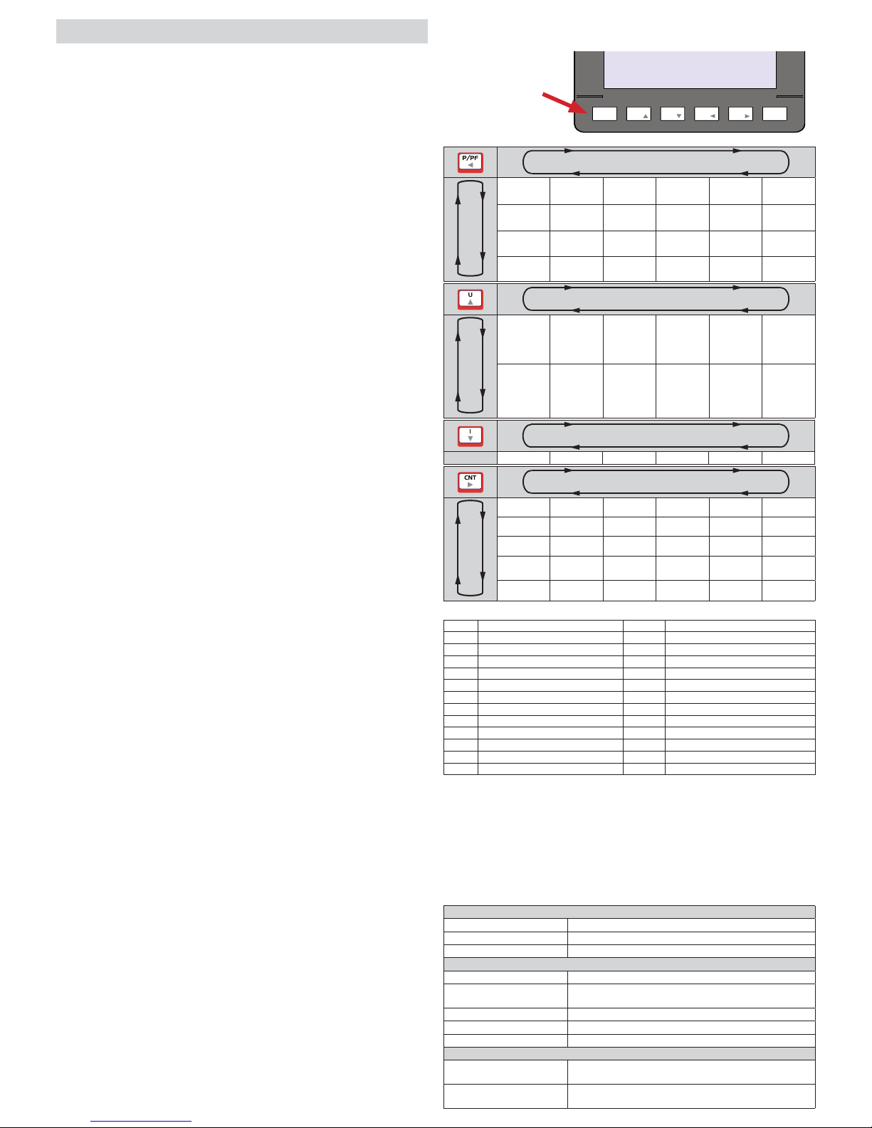
READINGS
ENTER
U
I
P/PF
CNT
ESCMENU
MEASURE LIST TABLE
(The parameters available vary according to instrument confi guration)
Short keypress
Long keypress
P P Avg Imp P Avg Exp P MD Imp P MD Exp
Q Q Avg Imp Q Avg Exp Q MD Imp Q MD Exp
S S Avg Imp S Avg Exp S MD Imp S MD Exp
PF
Short keypress
Long keypress
U L-N / f U THD L-N U L-N Min U L-N Max
U L-L / f U THD L-L U L-L Min U L-L Max
Short keypress
In I I THD I Max I AVG I MD
Short keypress
Long keypress
Ea Imp ∑ Ea Imp P Ea Exp ∑ Ea Exp P
Ea Imp ∑
Fase
Er Ind Imp ∑ Er Ind Imp P Er Ind Exp ∑ Er Ind Exp P
Er Ind Imp ∑
Fase
Er Cap Imp ∑ Er Cap Imp P Er Cap Exp ∑ Er Cap Exp P
Es Imp ∑ Es Imp P Es Exp ∑ Es Exp P
C1 Pulse ∑ C1 Pulse P
LEGEND OF PARAMETERS AND SYMBOLS
L-N Phase Neutral U Voltage
L-L Phase Phase I Current
THD Total Harmonic Distortion In Neutral current
Avg Average (rolling) value P Active Power
MD Maximum Demand Q Reactive Power
Imp Import value S Apparent Power
Exp Export value PF Power Factor
Ind Inductive Ea Active Energy
Cap Capacitive Er Reactive Energy
Min Minimum values (10 cycles time base) Es Apparent Energy
Max Maximum values (10 cycles time base) f Frequency
CNT ∑ Pulse count (total)
CNT P Pulse count (partial)
Keep pressed for 2 seconds
to enter confi guration Menu
Page 2
DESCRIPTION OF KEYS
Short keypress Long keypress
Confi rm parameter Setup confi rmation
Modify parameter
Modify parameter
Go to previous value Go to previous page
Go to next value Go to next page
Exit without saving the confi guration
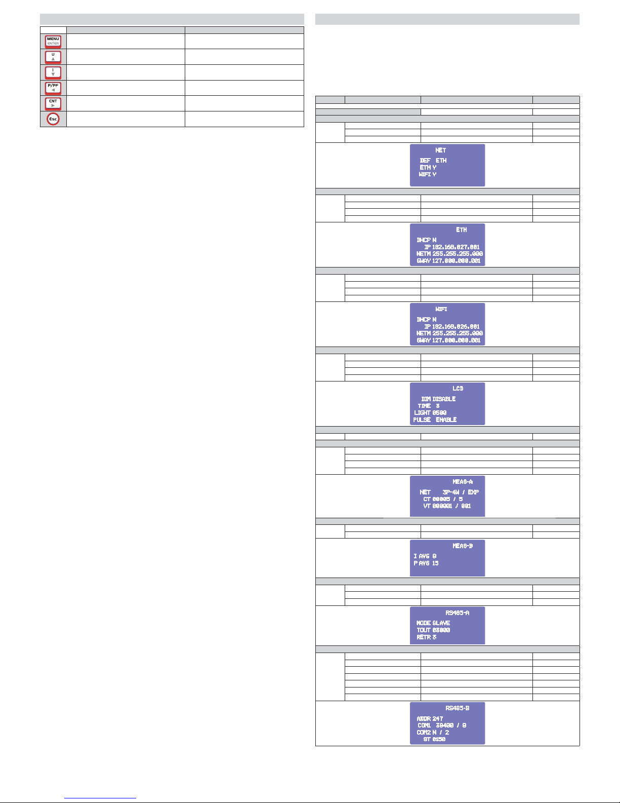
SETUP SEQUENCE
PAGE PARAMETERS VALUES AVAILABLE DEFAULT
PASSWORD REQUEST 0000 ... 9999 0000
NET Note n.4
DEF ETH, WIFI ETH
ETH N, Y Y
WIFI N, Y Y
NET
DEF
ETH
WIFI
ETH
Y
Y
NET
DEF
ETH
WIFI
ETH
Y
Y
ETH Note n.5
DHCP N, Y N
IP xxx.xxx.xxx.xxx 192.168.027.001
NETM xxx.xxx.xxx.xxx 255.255.255.000
GWAY xxx.xxx.xxx.xxx 127.000.000.001
ETH
DHCP
IP
NETM
GWAY
N
192.168.027.001
255.255.255.000
127.000.000.001
WIFI Note n.5
DHCP N, Y N
IP xxx.xxx.xxx.xxx 192.168.026.001
NETM xxx.xxx.xxx.xxx 255.255.255.000
GWAY xxx.xxx.xxx.xxx 127.000.000.001
WIFI
DHCP
IP
NETM
GWAY
N
192.168.026.001
255.255.255.000
127.000.000.001
LCD Note n.3
DIM DISABLE, ENABLE DISABLE
TIME 1...90 (sec) 3
LIGHT 300...1000 500
PULSE DISABLE, ENABLE ENABLE
LCD
DIM
TIME
LIGHT
PULSE
DISABLE
3
0500
ENABLE
CHANGE PWD
PWD 0000...9999 0000
MEAS1 Note n.1
NET 3PH-4W, 2PH-2W, 1PH-2W, 3PH-3W-2C 3P-4W
IMP / EXP EXP
CT 1...10000 / 1...5 5/5
VT 1...400000 / 1...300 1/1
MEAS-A
NET
CT
VT
3P-4W / EXP
00005 / 5
000001 / 001
MEAS2 Note n.2
I AVG 1...60 (MINUTES) 8
P AVG 1...60 (MINUTES) 15
MEAS-B
AVG
AVG815
I
P
RS485-1
MODE SLAVE, MASTER SLAVE
TOUT 100...10000 (ms) 3000
RETR 0...9 3
RS485-A
MODE
TOUT
RETR
SLAVE
03000
3
RS485-2
ADDR 1 ... 247 27
Swap None, B = byte, W = word, D = doubleword NONE
COM1 2400, 4800, 9600, 19200, 38400 38400
Data Bit 5...8 8
Parity N = none, E = even, O = odd N
Stop Bit 1 or 2 2
ST (Silent Time) 0...5000 (ms) 150
RS485-B
ADDR
COM1
COM2
ST
247
38400 / 8
N / 2
0150
DEVICE SETUP
Page 3
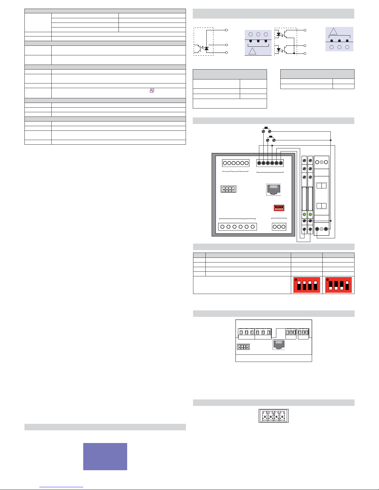
ETHERNETEXPBUS
DIP FUNCTION SLAVE MASTER *
1 Line termination resistance (120 Ohm) OFF ON
2 Fail safe resistance B (-) OFF ON
3 Fail safe resistance A (+) OFF ON
4 Not used OFF OFF
* with RS-485 Master PUK activated
ON
ON
LAN 10/100 ETHERNET PORT
The instrument is equipped with a Ethernet Lan 10/100 Auto-MDI/MDIX port.
For the connection can be used a data cable straight or crossover.
Note: the port is not a PoE (Power over Ethernet = device power supply via the Lan port)
type. The connection of the device to a PoE port is anyway accepted. The power supply
anyway must be always provided by an external power supplier.
DIP-SWITCH CONFIGURATION
EXPBUS PORT
The ExpBus port, confi gurable via Ethernet port on web pages:
- uses a multicast communication rated at 250kb/sec with collision management
- max cable length : 10 meters
- manages up to 16 modules (but technically can manage up to 126)
- uses the UTP cable, 4 wires used:
2 for the power supply at 9 Vdc
2 for the bidirectional communication
The modules will also power supply the ExpBus port
The cable must be connected in in-out modality (multidrop) as per the RS485 Bus.
Vcc
L
H
Gnd
INPUT & OUTPUT CONNECTION EXAMPLE
Digital Inputs
Supply voltage (external): from 10 to 30
Vdc
Current consumption: from 2 to 10mA
Max. count frequency 10 or 100Hz
N.B. For gas meters a galvanic separation is
needed per ATEX standards
Digital outputs (optocoupled NPN
transistor type for DIN 43864)
Maximum applicable voltage: 27 Vdc
Maximum switchable current: 27 mA
C191202
21
AUX
IN/OUT
!
Common
21
20
19
DO2
DO1
C102111
12
AUX
IN/OUT
!
INPUT & OUTPUT CONNECTION
DI (+)
11
10
DI (-)
12
12 201910 11
AUX IN/OUT
S1 S2 S1 S2 S1S2
I1 I2 I3
VOLTAGE INPUTS
POWER
SUPPLY
RS-485
CURRENT INPUTS
1817V1 V2 V3 N
AB
T
21
EXPBUS
ETHERNET
NO
C
NC
NO
C
NC
R
e
l
a
y
R
e
l
a
y
230 V~
24V =
N L
- +
NOTE n.1
NET 3PH-3W-2CT
2 phases 3 wires, triangle
3PH-4W 3 phases 4 wires, Star
2PH-2W 2 phases 2 wires, biphase
1PH-2W 1 phase 2 wires, monophase
CT Primary / Secondary of the current transformer (CT)
VT Primary / Secondary of the voltage transformer (VT)
NOTE n.2
P AVG Integration time of the average value (AVG) and peak value (MD) for
power (from 1 to 60 minutes)
I AVG Integration time of the average value (AVG) and peak value (MD) for
current (from 1 to 60 minutes)
NOTE n.3
DIM Enable / Disable dimming of the display
TIME Time in seconds after which the display luminosity is reduced. (With DIM
enabled)
LIGHT Luminosity level of the display
PULSE
Enable / Disable the fl ashing of the sine wave symbol
light near the
Electrex logo.
NOTE n.4
DEF Selects the default network interface to be used for the communication
ETH Enable / Disable the Ethernet (LAN) port
WIFI Enable / Disable the WIFI port
NOTE n.5
DHCP Enable / Disable the search for a DHCP server in the network
IP IP address of the network interface
NETM Subnet mask: defi nes the belonging range of a host within an IP
subnetwork
GWAY IP address of the gateway
MESSAGE “CFG ERROR”
During the set up operation a “CFG ERROR” message could appear. This means that
some wrong parameters are inserted.
CFG ERROR
Page 4
akse srl Via Aldo Moro, 39 42124 Reggio Emilia Italy
Tel. +39 0522 924 244 Fax +39 0522 924 245 [email protected] www.akse.it
P.I. 01544980350 R.E.A. 194296 Cap. Soc. Euro 85.800,00 i.v.
Subject to modifi cation without notice.
Edition 2017 05 02 ENG0137
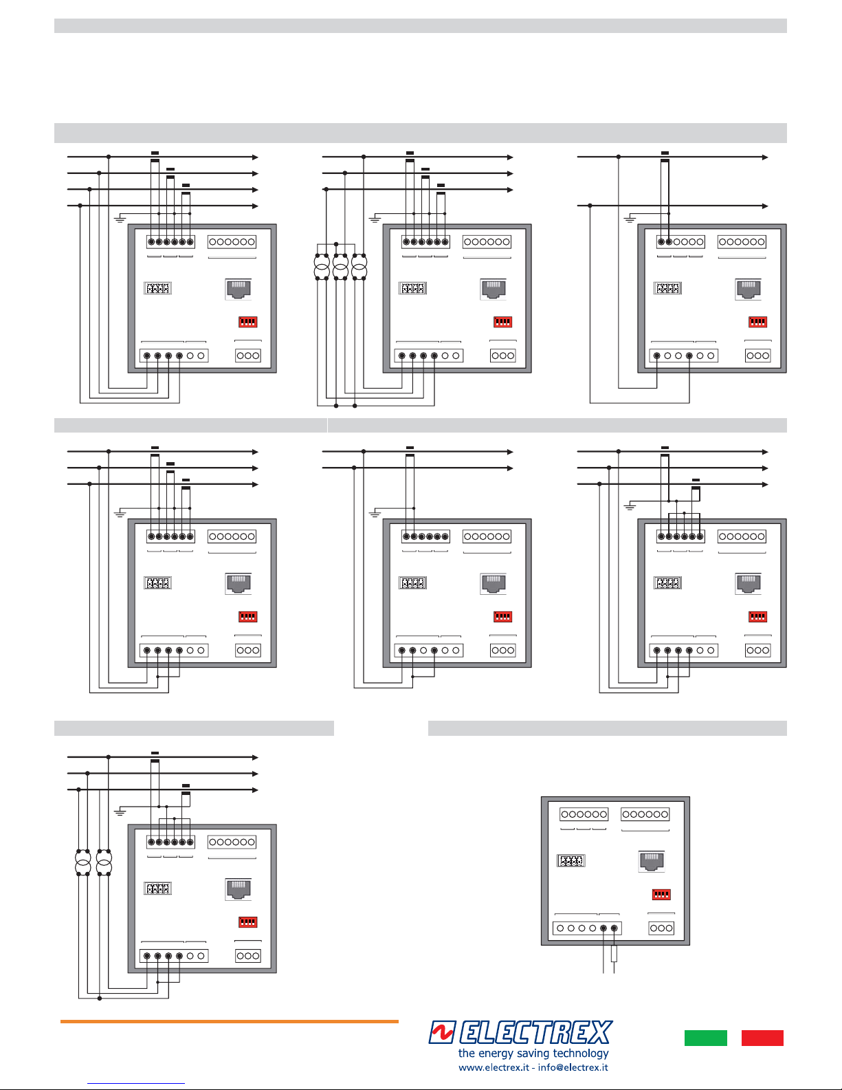
STAR 4W (4 WIRES) 3PH-4W LV
The instrument is fi tted with a separate power supply. The power supply terminals are
numbered (17 e 18). Use cables with max cross-section of 2,5 mm2 if stranded, 4 mm2 if
rigid.
POWER SUPPLY
VOLTAGE AND CURRENT CONNECTION
STAR 4W (4 WIRES) 3PH-4W MV
SINGLE PHASE (2 WIRES) 1PH-2W
TRIANGLE 3W (3 WIRES) 3PH-3W TRIANGLE 2CT (3 WIRES) 3PH-3W
TRIANGLE 2CT(3 WIRES) 3PH-3W MV
BI-PHASE (2 WIRES) 2PH-2W
Made
in Italy
Pensato, progettato e prodotto in Italia
Engineered and manufactured in Italy
12 201910 11
AUX IN/OUT
S1 S2 S1S2 S1 S2
I1 I2 I3
VOLTAGE INPUTS
POWER
SUPPLY
RS-485
CURRENT INPUTS
1817V1 V2 V3 N
AB
T
21
EXPBUS
ETHERNET
L1
N
S1 S2
P1 P2
12 201910 11
AUX IN/OUT
S1 S2 S1S2 S1 S2
I1 I2 I3
VOLTAGE INPUTS
POWER
SUPPLY
RS-485
CURRENT INPUTS
1817V1 V2 V3 N
AB
T
21
EXPBUS
ETHERNET
L1
L2
S1 S2
P1 P2
12 201910 11
AUX IN/OUT
S1 S2 S1S2 S1 S2
I1 I2 I3
VOLTAGE INPUTS
POWER
SUPPLY
RS-485
CURRENT INPUTS
1817V1 V2 V3 N
AB
T
21
EXPBUS
ETHERNET
L1
L2
L3
S1 S2
P1 P2
S1 S2
P1 P2
12 201910 11
AUX IN/OUT
S1 S2 S1S2 S1 S2
I1 I2 I3
VOLTAGE INPUTS
POWER
SUPPLY
RS-485
CURRENT INPUTS
1817V1 V2 V3 N
AB
T
21
EXPBUS
ETHERNET
L1
L2
L3
S1 S2
P1 P2
S1 S2
P1 P2
S1 S2
P1 P2
12 201910 11
AUX IN/OUT
S1 S2 S1S2 S1 S2
I1 I2 I3
VOLTAGE INPUTS
POWER
SUPPLY
RS-485
CURRENT INPUTS
1817V1 V2 V3 N
AB
T
21
EXPBUS
ETHERNET
L1
L2
L3
N
S1 S2
P1 P2
S1 S2
P1 P2
S1 S2
P1 P2
12 201910 11
AUX IN/OUT
S1 S2 S1S2 S1 S2
I1 I2 I3
VOLTAGE INPUTS
POWER
SUPPLY
RS-485
CURRENT INPUTS
1817V1 V2 V3 N
AB
T
21
EXPBUS
ETHERNET
L1
L2
L3
S1 S2
P1 P2
S1 S2
P1 P2
S1 S2
P1 P2
12 201910 11
AUX IN/OUT
S1 S2 S1S2 S1 S2
I1 I2 I3
VOLTAGE INPUTS
POWER
SUPPLY
RS-485
CURRENT INPUTS
1817V1 V2 V3 N
AB
T
21
EXPBUS
ETHERNET
L1
L2
L3
S1 S2
P1 P2
S1 S2
P1 P2
12 201910 11
AUX IN/OUT
S1 S2 S1S2 S1 S2
I1 I2 I3
VOLTAGE INPUTS
POWER
SUPPLY
RS-485
CURRENT INPUTS
1817V1 V2 V3 N
AB
T
21
EXPBUS
ETHERNET
LN
FUSE
(500mA T)
85 ÷ 265 V ±10%
Voltage connection: Use cables with max cross-section of 2,5 mm2 if stranded 4 mm2 if rigid and connect them to the clamps marked VOLTAGE INPUT on the instrument according
to the applicable diagrams that follow.
Current connection: It is necessary to use external CTs with a primary rating adequate to the load to be measured and with a 5A or 1A secondary rating. Connect the CT output(s) to
the terminals marked I1, I2, I3 (CURRENT INPUT) of the instrument according to the applicable diagrams that follow. Use cables with cross-section adequate to the VA rating of the CT
and to the distance to be covered. The max cross-section for the terminals is 2,5 mm2 if stranded and 4 mm2 if rigid.
Note: The CT secondary must always be in short circuit when not connected to the instrument in order to avoid damages and risks for the operator.
Scrupulously respect the matching of phase between the voltage signals and current signals (RTD) and the direction of insertion of CT (P1-P2 and S1-S2). Failure to comply with this
correspondence and connection diagrams gives rise to measurement errors. (*) The grounding of S2 must be close to the CT and not near the instrument.
 Loading...