

ElectraStream BEL 130, BEL 150, BETP 215, 200, 300 User Manual
...
heating products
User and Installation ManualUser and Installation Manual
User and Installation Manual
User and Installation ManualUser and Installation Manual
Single and Twin Coil Models
For owners, installers and service engineers
27/02/13
A complete cost effective solution for Hot and Cold water supply and Electric Central
Heating with water filled radiators, suitable for Self-contained Flats, Small Dwellings,
Offices, Home Offices and Granny Annexes.
9 kW (30,000 Btu) - for Heating and Hot Water
TT
win Coil Cylinder option available for SOLAR enerwin Coil Cylinder option available for SOLAR ener
T
win Coil Cylinder option available for SOLAR ener
TT
win Coil Cylinder option available for SOLAR enerwin Coil Cylinder option available for SOLAR ener
gygy
gy
gygy
..
.
..
1

Important Health and Safety Information for Installers and Service Engineers
Health and Safety at Work Act 1974
Consumer Protection Act 1987
COSHH Regulations 1988
The following information is given as a requirement of the
above legislation.
Great care is taken by GAH (HEATING PRODUCTS) LIMITED
to ensure that Electrastream systems are designed and
manufactured to meet general safety requirements when
properly used and installed as recommended in this manual.
It is the responsibility of Users and Engineers to ensure that
adequate protective clothing and glasses are worn when
working with the Electrastream system.
SEALS AND INSULATIONSEALS AND INSULATION
SEALS AND INSULATION
SEALS AND INSULATIONSEALS AND INSULATION
Insulation and sealing materials are used in the construction
of the Electrastream cylinders. Units are sealed and when
used in the manner for which they are intended the insulating
and sealing materials do not present any known hazard.
However always observe the following recommendations:-
1. Avoid inhalation of fibres or dust, wear face mask.
2. Avoid eye contamination by fibres or dust - wear eye
protection.
3. As far as possible avoid any skin contact with Fibreglass
Insulation, Glass Rope, Mineral Wool, Insulation Pads and
Ceramic Fibre.
HEALHEAL
HEAL
HEALHEAL
OTHER MATERIALSOTHER MATERIALS
OTHER MATERIALS
OTHER MATERIALSOTHER MATERIALS
SEALANTS, ADHESIVES AND PAINTS
Sealants, Adhesives and Paints are used in the construction of
the Electrastream components. When used in the manner for
which they are intended they do not present any known hazard.
ELECTRICELECTRIC
ELECTRIC
ELECTRICELECTRIC
The Cylinder Tri-Core Heater, Pump, Thermostats and Contactor
Box all have electrical supply of 230V (enough to endanger
life).
Always isolate before connection, adjustment, servicing and
repair.
When the Tri-Core Heater cover is removed high power live
electrical terminals are exposed.
ISOLATE THE TRI-CORE HEATER BEFORE REMOVING ITS
COVER.
Earth protection - Earth Continuity Conductors must be fitted
and must comply with IEE Wiring Regulations.
GAH (HEATING PRODUCTS) LIMITED will not accept
responsibility for any damage or personal injury caused
by not giving due consideration to the above safety
recommendations.
TH & SAFETYTH & SAFETY
TH & SAFETY
TH & SAFETYTH & SAFETY
In pursuance of a policy of constant development, GAH (HEATING PRODUCTS) LIMITED
reserve the right to change Electrastream parts or design without notice, therefore
certain details included in this manual may not be correct at the time of printing. Any
modification and improvements detailed in this manual does not commit GAH to update
any system previously supplied.
Manual Part No. ...................MAN1019
Manual Ref ..........................ES02
Issue ...................................13
Date ....................................25/02/13
PP
atent application 01514800.2atent application 01514800.2
P
atent application 01514800.2
PP
atent application 01514800.2atent application 01514800.2
©©
2010 GAH (HEATING PRODUCTS) L 2010 GAH (HEATING PRODUCTS) L
©
2010 GAH (HEATING PRODUCTS) L
2010 GAH (HEATING PRODUCTS) L 2010 GAH (HEATING PRODUCTS) L
©©
ElectrastrElectrastr
eam is a Team is a T
Electrastr
eam is a T
ElectrastrElectrastr
eam is a Team is a T
HTS REF GAH ELECTRASTREAM 25/02/13
Manual by Harber Technical Services Tel/Fax 01263 515444
E-mail:info@harbertech.co.uk www.harbertech.co.uk
2
rademark of GAH (HEATING PRODUCTS) Lrademark of GAH (HEATING PRODUCTS) L
rademark of GAH (HEATING PRODUCTS) L
rademark of GAH (HEATING PRODUCTS) Lrademark of GAH (HEATING PRODUCTS) L
TD.TD.
TD.
TD.TD.
TD.TD.
TD.
TD.TD.
GAH (Heating PrGAH (Heating Pr
GAH (Heating Pr
GAH (Heating PrGAH (Heating Pr
oducts) Ltd.oducts) Ltd.
oducts) Ltd.
oducts) Ltd.oducts) Ltd.
Building 846
Bentwaters Parks
Rendlesham
Woodbridge
Suffolk IP12 2TW
TT
el:el:
01394 42116001394 421160
T
el:
01394 421160
TT
el:el:
01394 42116001394 421160
Fax:Fax:
01394 42117001394 421170
Fax:
01394 421170
Fax:Fax:
01394 42117001394 421170
email: mail@gah.co.uk
www.gah.co.uk
CONTENTSCONTENTS
CONTENTS
CONTENTSCONTENTS
ImporImpor
tant Informationtant Information
Impor
tant Information
ImporImpor
tant Informationtant Information
Section 1 IntrSection 1 Intr
Section 1 Intr
Section 1 IntrSection 1 Intr
1-1 Introduction ---------------------------------------------- 5
1-2 System Layout ------------------------------------------- 8
1-3 Parts Supplied------------------------------------------- 11
1-4 The Electrastream System ------------------------------- 12
1-5 Tri Core Heater Operation -------------------------------- 13
oductionoduction
oduction
oductionoduction
----------------------------------------------------------------------------------
----------------------------------------- 4
----------------------------------------------------------------------------------
1 INTRODUCTION1 INTRODUCTION
1 INTRODUCTION
1 INTRODUCTION1 INTRODUCTION
2 OPERA2 OPERA
2 OPERA
2 OPERA2 OPERA
CONTENTSCONTENTS
CONTENTS
CONTENTSCONTENTS
TOR CONTROLSTOR CONTROLS
TOR CONTROLS
TOR CONTROLSTOR CONTROLS
Section 2 Operator ContrSection 2 Operator Contr
Section 2 Operator Contr
Section 2 Operator ContrSection 2 Operator Contr
2-1 System Control ------------------------------------------ 14
2-2 Electrastream Control Unit------------------------------- 16
2-3 Shut Off Valves ------------------------------------------ 20
2-4 Temperature & Pressure Relief Discharge ---------------- 22
2-5 Thermostatic Mixing Valve ------------------------------ 22
2-6 Servicing ------------------------------------------------ 22
Section 3 TSection 3 T
Section 3 T
Section 3 TSection 3 T
3-1 Specifications ------------------------------------------- 23
3-2 Dimensions --------------------------------------------- 25
3-3 Wiring --------------------------------------------------- 29
Section 4 InstallationSection 4 Installation
Section 4 Installation
Section 4 InstallationSection 4 Installation
4-1 Building Control ----------------------------------------- 31
4-2 Electrical ------------------------------------------------ 31
4-3 Hot Water System --------------------------------------- 33
4-4 Heating System ----------------------------------------- 37
4-5 Expansion Discharge ------------------------------------ 40
4-6 System Pressure ---------------------------------------- 43
4-7 Electrastream Connections - ---------------------------- 44
echnical Informationechnical Information
echnical Information
echnical Informationechnical Information
olsols
ols
olsols
3 TECHNICAL INFORMA3 TECHNICAL INFORMA
3 TECHNICAL INFORMA
3 TECHNICAL INFORMA3 TECHNICAL INFORMA
4 INST4 INST
4 INST
4 INST4 INST
5 COMMISSIONING5 COMMISSIONING
5 COMMISSIONING
5 COMMISSIONING5 COMMISSIONING
ALLAALLA
ALLA
ALLAALLA
6 SERVICING6 SERVICING
6 SERVICING
6 SERVICING6 SERVICING
TIONTION
TION
TIONTION
TIONTION
TION
TIONTION
Section 5 CommissioningSection 5 Commissioning
Section 5 Commissioning
Section 5 CommissioningSection 5 Commissioning
5-1 Commissioning ----------------------------------------- 47
Section 6 ServicingSection 6 Servicing
Section 6 Servicing
Section 6 ServicingSection 6 Servicing
6-1 Routine Service ----------------------------------------- 50
Section 7 Fault FindingSection 7 Fault Finding
Section 7 Fault Finding
Section 7 Fault FindingSection 7 Fault Finding
7-1 Fault Finding -------------------------------------------- 52
Health & SafetyHealth & Safety
Health & Safety
Health & SafetyHealth & Safety
------------------------------------------------------------
------------------------------ Inside Front Cover
------------------------------------------------------------
7 F7 F
AULAUL
7 F
AUL
7 F7 F
AULAUL
HEALHEAL
TH & SAFETYTH & SAFETY
HEAL
TH & SAFETY
HEALHEAL
TH & SAFETYTH & SAFETY
T FINDINGT FINDING
T FINDING
T FINDINGT FINDING
IMPORTANT
BEFORE STARTING THE INSTALLATION OF THE ELECTRASTREAM CHECK ALL COMPONENTS HAVE
BEEN DELIVERED AND ARE IN SATISFACTORY CONDITION - Refer to 1-3 .
3
IMPORTIMPORT
IMPORT
IMPORTIMPORT
IMPORTANT INFORMATION
ANT INFORMAANT INFORMA
ANT INFORMA
ANT INFORMAANT INFORMA
TIONTION
TION
TIONTION
BEFORE STARBEFORE STAR
BEFORE STAR
BEFORE STARBEFORE STAR
IN SATISFACTORY CONDITION - RIN SATISFACTORY CONDITION - R
IN SATISFACTORY CONDITION - R
IN SATISFACTORY CONDITION - RIN SATISFACTORY CONDITION - R
TING THE INSTALLATION OF THE ELECTRASTREAM CHECK ALL COMPONENTS HAVE BEEN DELIVERED AND ARETING THE INSTALLATION OF THE ELECTRASTREAM CHECK ALL COMPONENTS HAVE BEEN DELIVERED AND ARE
TING THE INSTALLATION OF THE ELECTRASTREAM CHECK ALL COMPONENTS HAVE BEEN DELIVERED AND ARE
TING THE INSTALLATION OF THE ELECTRASTREAM CHECK ALL COMPONENTS HAVE BEEN DELIVERED AND ARETING THE INSTALLATION OF THE ELECTRASTREAM CHECK ALL COMPONENTS HAVE BEEN DELIVERED AND ARE
efer to 1-3.efer to 1-3.
efer to 1-3.
efer to 1-3.efer to 1-3.
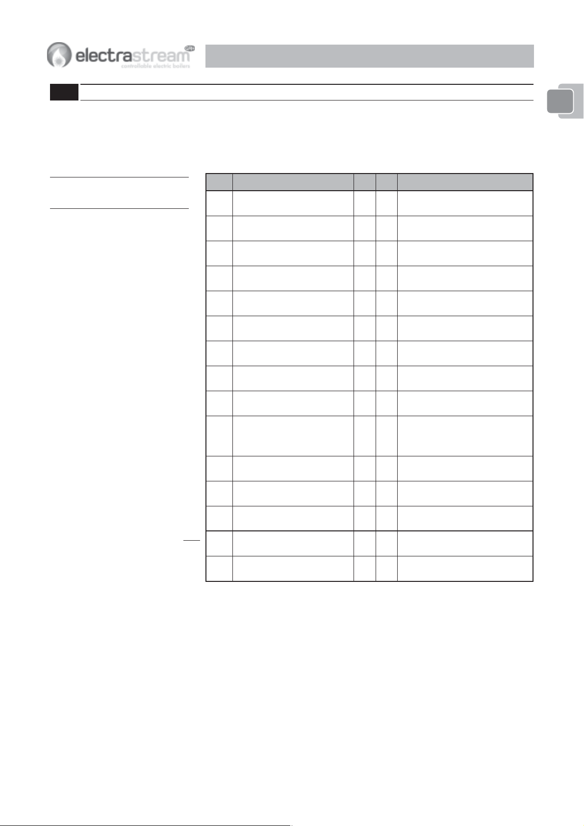
Delivery
Standard Electrastream systems will be delivered wrapped on single pallet with cylinder together with box containing control box
and loose components.
Pre-Plumbed Electrastream systems will be delivered wrapped on single pallet with cylinder, control box and all components fully
assembled.
Pack should be lifted using suitable sized pallet truck or fork lift truck.
WEIGHTS OF PACKED CYLINDERS and COMPONENTS
ledoMthgiewkcaP
031LEB
051LEB
smetsySlioCelgniS
✓
gk55
gk06
ledoMthgiewkcaP
031PEB
051PEB
R521PEB
lioCelgniS
smetsySdebmulP-erP
✓
gk17
ledoMthgiewkcaP
512PTEB
gk67003gk05
gk77
lioCniwT
smetsySdebmulP-erP
✓
ledoMthgiewkcaP
gk771002gk53
'P'sulP
rotalumuccA
Storage
Prior to installation the cylinder and box should remain on its pallet with wrapping intact and stored upright. The cylinder and
components must be stored safely in a dry, frost free environment and protected from accidental damage.
✓
WARNING TO THE USERWARNING TO THE USER
WARNING TO THE USER
WARNING TO THE USERWARNING TO THE USER
DO NOT rDO NOT r
DO NOT r
DO NOT rDO NOT r
In the event of hot water/steam being emitted at the discharIn the event of hot water/steam being emitted at the dischar
In the event of hot water/steam being emitted at the dischar
In the event of hot water/steam being emitted at the discharIn the event of hot water/steam being emitted at the dischar
Fault Finding section 7.Fault Finding section 7.
Fault Finding section 7.
Fault Finding section 7.Fault Finding section 7.
If the ElectrastrIf the Electrastr
If the Electrastr
If the ElectrastrIf the Electrastr
This installation is subject to Building RThis installation is subject to Building R
This installation is subject to Building R
This installation is subject to Building RThis installation is subject to Building R
Use only manufacturUse only manufactur
Use only manufactur
Use only manufacturUse only manufactur
The following Information must be prThe following Information must be pr
The following Information must be pr
The following Information must be prThe following Information must be pr
emove or adjust any component paremove or adjust any component par
emove or adjust any component par
emove or adjust any component paremove or adjust any component par
eam system develops a fault or is not operating as expected: contact the eam system develops a fault or is not operating as expected: contact the
eam system develops a fault or is not operating as expected: contact the
eam system develops a fault or is not operating as expected: contact the eam system develops a fault or is not operating as expected: contact the
IMPORIMPOR
TANT TO THE INSTALLERTANT TO THE INSTALLER
IMPOR
TANT TO THE INSTALLER
IMPORIMPOR
TANT TO THE INSTALLERTANT TO THE INSTALLER
er’s rer’s r
ecommended recommended r
er’s r
ecommended r
er’s rer’s r
ecommended recommended r
ovided:-ovided:-
ovided:-
ovided:-ovided:-
INSTALLED BY:-
Name ............................................................................................................
Address .........................................................................................................
Tel. ................................................................................................................
Completion Date ...........................................................................................
ELECTRICS BY:-
Name ............................................................................................................
t of the unvented water heater: contact the t of the unvented water heater: contact the
t of the unvented water heater: contact the
t of the unvented water heater: contact the t of the unvented water heater: contact the
egulation Appregulation Appr
egulation Appr
egulation Appregulation Appr
eplacement pareplacement par
eplacement par
eplacement pareplacement par
oval, notifoval, notif
oval, notif
oval, notifoval, notif
ts.ts.
ts.
ts.ts.
INSTALLERINSTALLER
INSTALLER
INSTALLERINSTALLER
ge pipe or tundish, switch the system Off and contact installer - rge pipe or tundish, switch the system Off and contact installer - r
ge pipe or tundish, switch the system Off and contact installer - r
ge pipe or tundish, switch the system Off and contact installer - rge pipe or tundish, switch the system Off and contact installer - r
INSTALLERINSTALLER
INSTALLER
INSTALLERINSTALLER
y the Ly the L
ocal Authority of intention to install.ocal Authority of intention to install.
y the L
ocal Authority of intention to install.
y the Ly the L
ocal Authority of intention to install.ocal Authority of intention to install.
..
.
..
..
.
..
efer toefer to
efer to
efer toefer to
Address .........................................................................................................
Tel. ................................................................................................................
Completion Date ...........................................................................................
4
1-1 Introduction
GAH ElectrastrGAH Electrastr
GAH Electrastr
GAH ElectrastrGAH Electrastr
eam Systems aream Systems ar
eam Systems ar
eam Systems aream Systems ar
e pre pr
otected pending patent applications.otected pending patent applications.
e pr
otected pending patent applications.
e pre pr
otected pending patent applications.otected pending patent applications.
INTRODUCTION 1INTRODUCTION 1
INTRODUCTION 1
INTRODUCTION 1INTRODUCTION 1
11
1
11
ElectrastrElectrastr
Electrastr
ElectrastrElectrastr
This Handbook has been compiled to assist in the Installation and Operation of GAH (HEATING PRODUCTS) LIMITEDThis Handbook has been compiled to assist in the Installation and Operation of GAH (HEATING PRODUCTS) LIMITED
This Handbook has been compiled to assist in the Installation and Operation of GAH (HEATING PRODUCTS) LIMITED
This Handbook has been compiled to assist in the Installation and Operation of GAH (HEATING PRODUCTS) LIMITEDThis Handbook has been compiled to assist in the Installation and Operation of GAH (HEATING PRODUCTS) LIMITED
ElectrastrElectrastr
Electrastr
ElectrastrElectrastr
© 2009 GAH (HEATING PRODUCTS) LIMITED© 2009 GAH (HEATING PRODUCTS) LIMITED
© 2009 GAH (HEATING PRODUCTS) LIMITED
© 2009 GAH (HEATING PRODUCTS) LIMITED© 2009 GAH (HEATING PRODUCTS) LIMITED
Notified Body NB 0558Notified Body NB 0558
Notified Body NB 0558
Notified Body NB 0558Notified Body NB 0558
After installation the Installer of the system should give full operating instructions to the householder for the ElectrastrAfter installation the Installer of the system should give full operating instructions to the householder for the Electrastr
After installation the Installer of the system should give full operating instructions to the householder for the Electrastr
After installation the Installer of the system should give full operating instructions to the householder for the ElectrastrAfter installation the Installer of the system should give full operating instructions to the householder for the Electrastr
System. This User and Installation Manual must be left for the end userSystem. This User and Installation Manual must be left for the end user
System. This User and Installation Manual must be left for the end user
System. This User and Installation Manual must be left for the end userSystem. This User and Installation Manual must be left for the end user
eam is a Team is a T
eam is a T
eam is a Team is a T
eam domestic hot water and heating system.eam domestic hot water and heating system.
eam domestic hot water and heating system.
eam domestic hot water and heating system.eam domestic hot water and heating system.
rademark of GAH (HEATING PRODUCTS) Lrademark of GAH (HEATING PRODUCTS) L
rademark of GAH (HEATING PRODUCTS) L
rademark of GAH (HEATING PRODUCTS) Lrademark of GAH (HEATING PRODUCTS) L
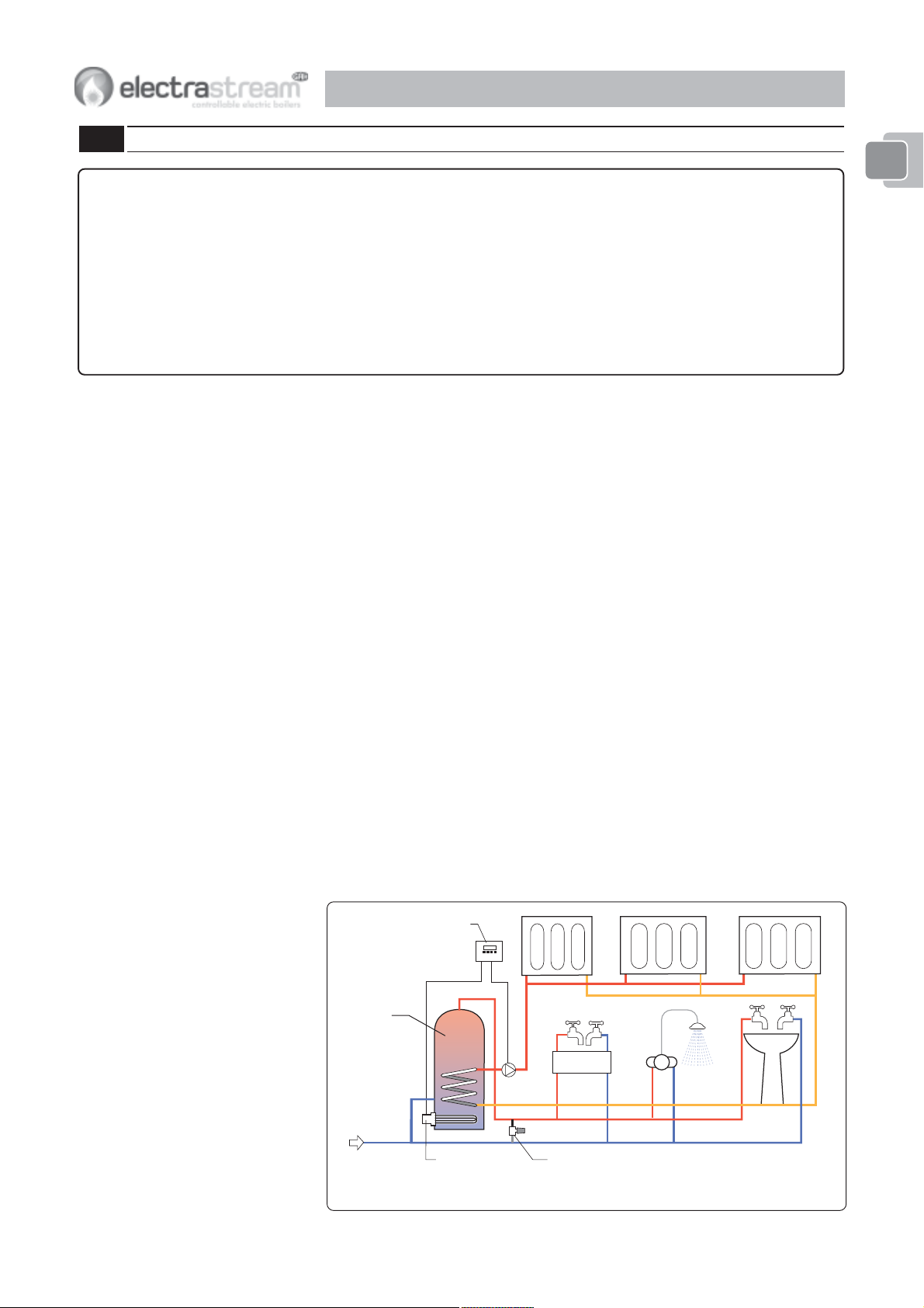
1-1.1 The Electrastream System
The Electrastream system by GAH (Heating Products) Ltd. has been developed as a cost
effective solution for domestic hot and cold water and electric central heating with water
filled radiators.
Electrastream is a 9kW - 30,000 Btu system suitable for flats, small dwellings, offices,
home offices and granny annexes.
1-1.2 Electrastream Options Available
Consult GAH (Heating Products) Ltd.
1-1.3 Basic Principles
ELECTRASTREAM
Water in the unvented cylinder is heated by the high powered titanium electric tri-core
heater. Hot water is drawn from the cylinder and mixed with cold water by a thermostatic
mixing valve; this ensures safer lower temperatures at the hot water outlets.
The hot water within the unvented indirect cylinder also heats the water for the heating
system via the indirect coil within the cylinder. The circulating pump for the heating
system is controlled by a thermostat and programmable timer with override so that heat
is available on demand, providing there is a supply of hot water.
TD.TD.
TD.
TD.TD.
..
.
..
eameam
eam
eameam
ELECTRASTREAM PRE-PIPED
Operationally the same as the Electrastream but supplied pre-piped and assembled onto
a mounting frame.
Electrastream
Control
Unit
Unvented
Indirect
Cylinder
Pump
Incoming
Water Main
Tri-core Heater
Thermostatic
Mixing Valve
Fig. 1-1a Electrastream
5
INTRODUCTION 1INTRODUCTION 1
INTRODUCTION 1
INTRODUCTION 1INTRODUCTION 1
11
1
11
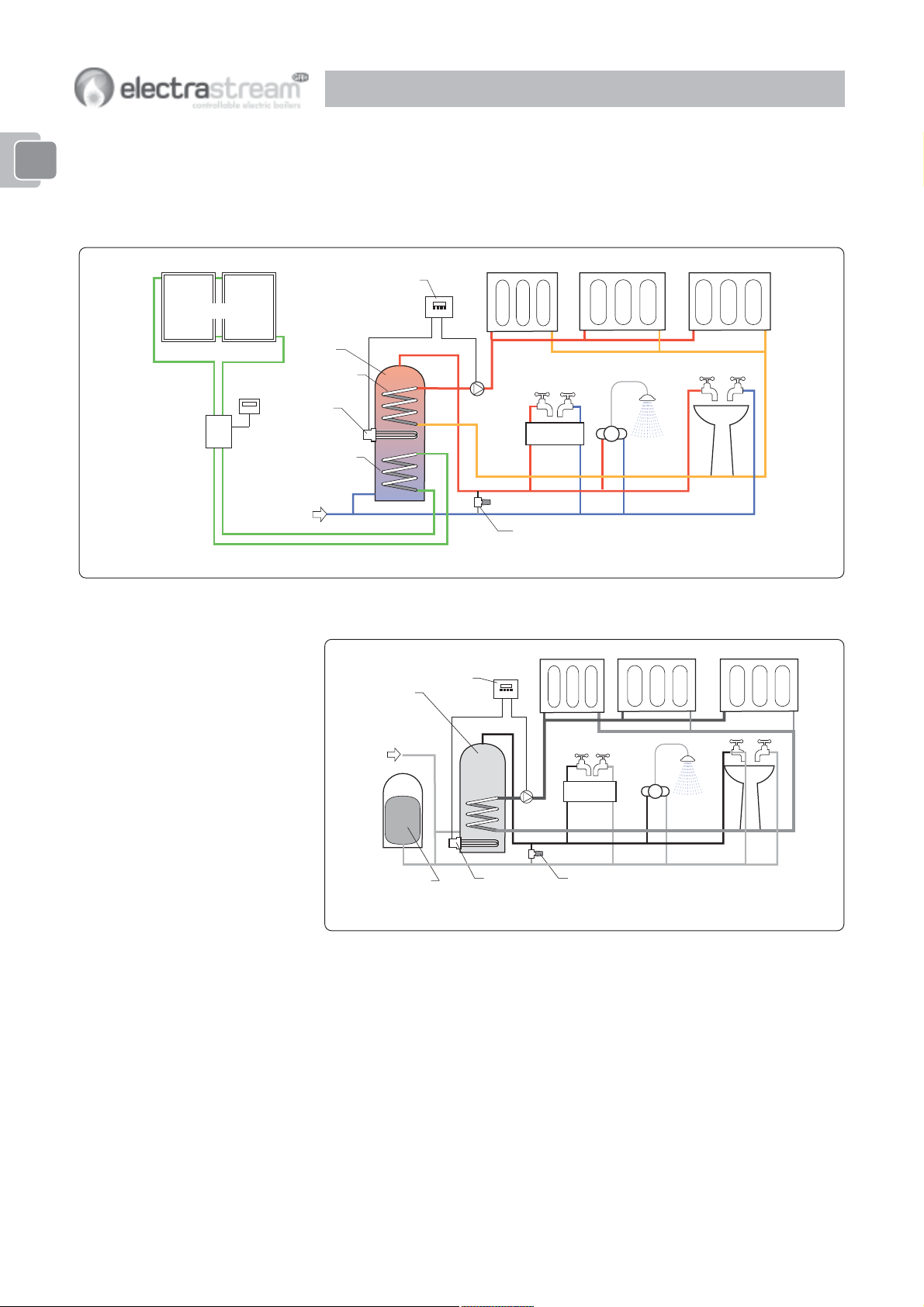
ELECTRASTREAM TWIN COIL
Operationally the same as the Electrastream but supplied with a twin coil cylinder which
enables the Electrastream to be used in conjunction with alternative energy systems e.g.
Solar.
Electrastream
Control
Solar Collectors
Solar
Control
Unvented
Indirect
Cylinder
Electrastream
Coil
Tri-core
Heater
Primary Coil
for alternative
energy
Incoming
Water Main
Fig. 1-1b Electrastream Twin Coil - typical solar arrangement
Unit
Pump
Thermostatic
Mixing Valve
ELECTRASTREAM PLUS
Unvented
Indirect
Cylinder
Incoming
Water Main
Accumulator
Cold water storage
Electrastream
Control
Unit
Pump
Tri-core
Heater
Fig. 1-1c Electrastream Plus
Thermostatic
Mixing Valve
The Electrastream Plus system is supplied with a cold water storage accumulator.
The accumulator has an internally controlled butyl diaphragm, incoming cold water is
stored within this diaphragm at mains pressure. The air space between the diaphragm
and the accumulator case is pressurised, this balances the supply and maintains
pressure to the unvented hot water cylinder and cold outlets. When hot and cold water
outlets are turned on, the stored water from the accumulator supplements water from the
incoming main, this results in consistent pressure and flow to all taps, showers and baths
even when outlets are used simultaneously. Pressure will be sustained for as long as the
accumulator is holding sufficient volume of water.
ELECTRASTREAM PLUS PRE-PIPED
Operationally the same as the Electrastream Plus but supplied pre-piped and assembled
onto a mounting frame, the cold storage accumulator is supplied separately.
6
Note
For components supplied with system refer
to page 9.
Note
Further options are available consult GAH
(Heating Products) Ltd.
INTRODUCTION 1INTRODUCTION 1
INTRODUCTION 1
INTRODUCTION 1INTRODUCTION 1
1-1.4 Electrastream System Features
ELECTRASTREAM AND ELECTRASTREAM TWIN COIL
1. Only water and electric services required.
2. No gas or oil - no Boiler.
3. Central heating with conventional water filled radiators.
4. Heat on demand 24 hours a day.
5. Can be timed for economy tariff.
6. Far more flexible heating control than storage radiators.
7. Hot water to taps and shower from unvented cylinder.
8. Hot water to outlets temperature controlled by thermostatic mixing valve.
9. Mains pressure to hot and cold outlets.
10. All plumbing, water storage and controls are within the dwelling - no header tank.
11. Low maintenance cost, no CORGI Landlord Certificate required.
12. 9kW titanium tri-core heater (combined 3 x 3kW).
13. Tri-core heater will still work should one or two of its three elements fail.
14. Stainless Steel Unvented Cylinder with 25 years guarantee.
11
1
11
ELECTRASTREAM TWIN COIL
1. Cylinder with primary coil for alternative energy source typically solar and ground
source.
ELECTRASTREAM PLUS ONLY
1. Balanced hot and cold supply to taps.
2. All taps and showers at maximum system pressure.
3. Pressure maintained for both hot and cold taps even when other taps are open
(subject to volume used).
noitpOledoMedoCrednilyC
maertsartcelE031LEB
depip-erPmaertsartcelE521PEB
maertsartcelE
maertsartcelE051LEB
depip-erPmaertsartcelE051PEB
lioCniwTmaertsartcelEdepip-erPmaertsartcelE512PTEBliocniwtertil512
ertil031
ertil051
sulP rotalumuccA
031LEBmaertsartcelEP031LEB
ertil031
031PEBdepip-erPmaertsartcelEP031PEB
sulPmaertsartcelE
051LEBmaertsartcelEP051LEB
ertil051
051PEBdepip-erPmaertsartcelEP051PEB
sulPlioCniwTmaertsartcelE512PTEBdepip-erPmaertsartcelEP012PTEBliocniwtertil512
002ledoM
ertil071
7
INTRODUCTION 1INTRODUCTION 1
INTRODUCTION 1
INTRODUCTION 1INTRODUCTION 1
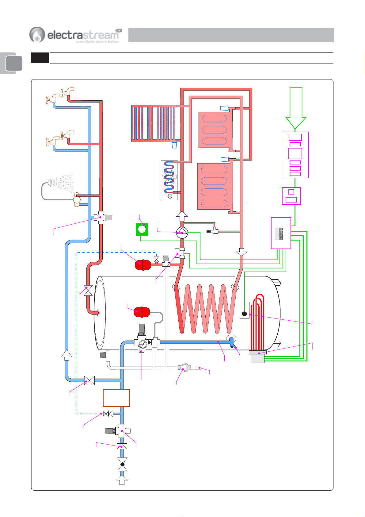
1-2 System Layout
11
1
11
1-2.1 Electrastream
Economy Tariff
22mm
3Thermostatic Mixing Valve -
limits temperature of hot water to taps
Thermostatic
Shower
Hot supply to taps
Towel Rail
Shower Room
3Heating Expansion Vessel 8l
No valves to be fitted between PRV
and Expansion Vessel
3Hot Water
Expansion
Kitchen
Kick Space Heater
Room Thermostat
3Pump
& valves
Vessel
3Motorised
Valve
3PRV
3
28mm
FLOW 22mm
Bypass
RCD
Consumer Unit with RCD
2 Pole
Isolator
Control Unit
3Electrastream
RETURN 22mm
3
28mm
3Isolating Valve
Balanced cold supply to taps
3Isolating Valve
3TPRV
Single Check Valve
3Heating System Fill 15mm
22mm Incoming
Cylinder
3Unvented
22mm
Water
(option)
Softener
mains supply
3Cylinder Temperature Sensor
& Thermal Cut Out
PRV
15mm
15mm
3Tundish
3Combination Valve
3.5 Bar Pressure
Reducing Valve
3
Drain 15mm
Discharge
No valves to be fitted between
Cylinder and PRV
Fig. 1-2a Typical Schematic Installation - Electrastream
3Tri-core Heater Combined 3 x 3kW
8
a
r
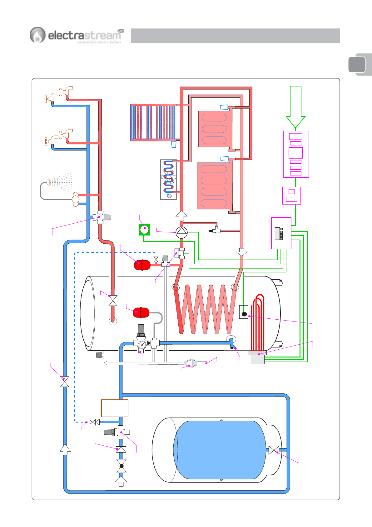
1-2.2 Electrastream Plus
INTRODUCTION 1INTRODUCTION 1
INTRODUCTION 1
INTRODUCTION 1INTRODUCTION 1
11
1
11
Hot supply to t
Thermostatic
Shower
✓Thermostatic Mixing Valve -
limits temperature of hot water to taps
Towel Rail
Shower Room
Room Thermostat
✓Heating Expansion Vessel 8l
No valves to be fitted between PRV
and Expansion Vessel
Vessel
Expansion
✓Hot Water
Kitchen
Kick Space Heater
FLOW 22mm
✓Pump
& valves
✓PRV
✓
28mm
✓Motorised
Valve
Bypass
✓
RETURN 22mm
28mm
Control Unit
✓Electrastream
Economy Ta
RCD
Consumer Unit with RCD
2 Pole
Isolator
Cylinder
✓Unvented
✓Isolating Valve
✓
✓ Isolating Valve
✓TPRV
22mm
Water
(option)
Softener
Balanced cold supply to taps
mains supply
22mm Incoming
Single Check Valve
✓Heating System Fill 15mm
PRV
15mm
✓Combination
Valve
Accumulator
✓
3.5 Bar Pressure
Reducing Valve
✓Tundish
✓
Discharge
Cold water storage
Drain 15mm
22mm
✓Cylinder Temperature Sensor
& Thermal Cut Out
Fig. 1-2b Typical Schematic Installation - Electrastream Plus 130 & 150
✓Tri-core Heater Combined 3 x 3kW
✓ Isolating Valve
9
INTRODUCTION 1INTRODUCTION 1
INTRODUCTION 1
INTRODUCTION 1INTRODUCTION 1
11
1
11
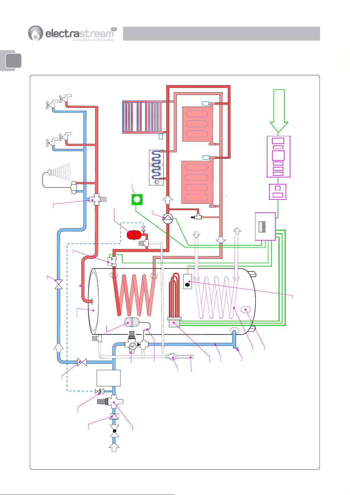
1-2.3 Twin Coil
3Thermostatic Mixing Valve -
limits temperature of hot water to taps
3Motorised
Thermostatic
Shower
Valve
Towel Rail
Shower Room
Hot supply to taps
3Heating Expansion Vessel 8l
No valves to be fitted between PRV
and Expansion Vessel
3
28mm
Kitchen
Room Thermostat
Kick Space Heater
3Pump
3PRV
& valves
3
28mm
FLOW 22mm
Bypass
source Flow
Alternative heat
source Return
Alternative heat
RETURN 22mm
3Electrastream
Control Unit
Economy Tariff
RCD
Consumer Unit with RCD
2 Pole
Isolator
10
3 Full Bore Isolating Valve
Cylinder
3Twin Coil Unvented
Balanced cold supply to taps
3Isolating Valve
3Heating System Fill 15mm
3TPRV
Single Check Valve
22mm
22 mm
Vessel
3HW Expansion
22mm
Water
(option)
Softener
Incoming
mains supply
3Combination Valve
3.5 Bar Pressure
Reducing Valve (option)
15mm
3
Fig. 1-2c Typical Schematic Installation - Electrastream Twin Coil 215, 255 & 305
PRV
Discharge
3Tundish
No valves to be fitted between PRV
and Expansion Vessel
22mm
Drain 15mm
No valves to be fitted between
Cylinder and PRV
3Tri-core Heater Combined 3 x 3kw
Primary Coil
Lower Immersion Heater
Tapping Blanked
3Cylinder Temperature Sensor & Thermal Cut Out
1-3 Parts Supplied
Note
On Electrastream Pre-piped units,
components are supplied already
assembled.
INTRODUCTION 1INTRODUCTION 1
INTRODUCTION 1
INTRODUCTION 1INTRODUCTION 1
Standard Electrastream systems will be delivered wrapped on single pallet with cylinder
together with box containing control box, expansion vessels and loose components.
Pre-Plumbed Electrastream systems will be delivered wrapped on single pallet with
cylinder, control box, expansion vessels and all components fully assembled.
metI traP .ytQ
1
lortnoCmaertsartcelE1
✓
setoN
rosneserutarepmetrednilycw/C
11
1
11
2
3
4
5
retaeHeroc-irTWk91
pmuPgnitalucriCHAG1
sevlaVgnitalosIpmuP2
6
7
8
evlaVnoitanibmoC1
9
01
11
21
evlaVdesirotoM1
tiKsgnittiF+rednilyCdetnevnU1
muinatiT
mm22
evlaVgnixiMcitatsomrehT1
tiK&lesseVnoisnapxEl8WHD1
xoBtatsomrehTrednilyC1
ssarBPSB"¾xmm22relpuoCIM4
evlaVreveLeroBlluFmm222
troP2
metsysdetcelesrofdeziS
Wk3x3denibmoC
esahPelgniSV032
morfretawtohhtiwretawdlocsdnelB
.spatrofrednilyc
,eguaGerusserP,pooLgnilliFw/C-etihW
partSdnatekcarB&VRPT
.)evlaVgnicudeRerusserP(VRPsedulcnI
.tatsedirrevolaunamw/C
nIdloCrednilyC-1
tuOtoHrednilyC-1
wolFgnitaeHrednilyC-1
nruteRgnitaeHrednilyC-1
spaTotylppuSdloC-1
spaTotylppuStoH-1
Electrastream Plus only
31
41
tiK&lesseV
rotalumuccA1
51
noisnapxEl8metsySgnitaeH
evlaVreveLeroBlluFmm221
1
partSdnatekcarB&VRPT
evlaVffOtuhSrotalumuccA
,eguaGerusserP,pooLgnilliFw/C-deR
l003rol002ledoMegarotSretaWdloC
11

INTRODUCTION 1 INTRODUCTION 1
INTRODUCTION 1
INTRODUCTION 1 INTRODUCTION 1
1-4 The Electrastream System
11
1
11
1-4.1 Hot & Cold Water Supply
Refer to fig. 1-2a for Electrastream.
Refer to fig. 1-2b for Electrastream Twin Coil
The incoming mains water supply is connected to the combination valve which is
Note
All installations must comply with relevant
regulations - refer to section 4-1.
assembled to the unvented indirect hot water cylinder. The combination valve has an
integral check valve. A single check valve is supplied, this is only required to be fitted if
back syphonage is possible from any item fitted prior to the combination valve.
Provision should also be provided in the cold supply for:-
1. Heating system fill.
2. Drinking water.
3. Water softener (when applicable).
4. Outside tap (when applicable).
The combination valve limits the incoming pressure to 3.5 Bar, it has an integral nonreturn valve and pressure relief valve (PRV).
Supply to the hot outlets is taken from the cylinder and mixed with cold water by the
thermostatic mixing valve, this ensures that a safer lower temperature hot water is
available at outlets.
Note
The alternative heat source must be
configured correctly to be used with the
GAH Electrastream system.
Note
The final fill of the heating system should
include the correct percentage of suitable
scale/corrosion inhibitor.
Cold supply to all outlets is taken direct from the main supply. If the mains pressure is
high (over 3.5 Bar) a 3.5 Bar pressure reducing valve is recommended.
1-4.2 Twin Coil - Alternative Heat Source
Twin Coil Cylinders have two coils, the upper coil is connected to the Electrastream
heating system. The Electrastream high powered titanium electric tri-core heater is
positioned about halfway up the cylinder so that it is only used to heat the water in the
upper part of the cylinder.
The lower coil is heated by the chosen alternative heat source (e.g. solar), this will heat
the water in the whole cylinder when ‘energy’ is available resulting in optimum efficiency.
1-4.3 System Control
The Electrastream system is controlled by a purpose designed Electrastream Control
Unit, this controls the hot water and heating ON/OFF times together with the heating
pump and valve. The control also has a dedicated programme that ensures efficient use
of electricity by selecting how many of the three immersion heater elements are required
to meet the current demand for heating or hot water.
1-4.4 Heating System
The heating system is for water filled radiators on a standard ‘sealed system’. The water
for the heating is heated by being pumped through the indirect coil of the cylinder. A
room thermostat and the Electrastream Control Unit’s programmable timers control the
circulating pump and motorised valve.
12
1-4.5 Electric System
The unvented cylinder is heated by a 240V, 9kW (combined 3 x 3kW) titanium tri-core
heater. This is controlled by the cylinder temperature sensor and the Electrastream
Control Unit.
Electrastream is designed to make full use of economy tariff electricity supplies and the
wiring must be arranged to make full use of this.
GAH offer a range of quality Water
Softeners, for information contact
GAH (HEATING PRODUCTS) LTD.
Note
When a water softener is fitted, the takeoffs for heating system fill, drinking water
and outside tap (when applicable), must
be positioned before the water softener.
INTRODUCTION 1INTRODUCTION 1
INTRODUCTION 1
INTRODUCTION 1INTRODUCTION 1
1-4.6 Output
The tri-core heater provides 9kW (30,000 Btu) for heating and hot water.
1-4.7 Scale Protection
IMPORTANT All installations should have a scale protection device fitted
and in areas known to have hard water, a water softening device is
strongly recommended. The cylinder is not guaranteed against damage
caused by scale. Higher water temperatures of 65°C and above can
cause excessive scale.
GAH recommend and promote the use of scale prevention devices and water softeners in
areas that are known to have hard water. Installed correctly they prolong the life of
equipment and help prevent limescale formation in the pipework. Water softeners
provide the advantages of soft water, as well as preventing scale build up on taps and
shower heads.
Water softeners and any mains fed system must be of adequate capacity and should be
installed with suitably sized hoses to prevent any possibility of flow reduction.
1-4.8 Frost Protection
When planning the installation location of both the accumulator and the unvented
cylinder, consideration must be given to the risk of frost and the use of frost protection.
The design of the accumulator gives it a degree of frost protection enabling it to be
located within the dwelling, loft space or garage without further protection.
The cylinder can also be installed within the dwelling or loft space without further
protection.
Cylinders or accumulators must have frost protection when they are installed where low
temperatures could be a potential problem. Cylinders can be protected by a frost
thermostat.
To comply with Building Regulations, all necessary pipework must be suitably lagged.
11
1
11
1-5 Tri-core Heater Operation
Note
Refer to 2-2.2 for display settings.
IMPORTANT
On twin coil cylinders the
Electrastream tri-core heater must
be fitted to the upper immersion
heater tapping.
1-4.9 Handling and Storage
The Electrastream system will be delivered fully wrapped and palleted.
Lift the package carefully using a safe and suitable lifting method.
Keep the packaging intact and store in a secure dry and weatherproof area prior to
installation.
The three elements of the tri-core heater are switched on and off by the Electrasteam
Control Unit. They have a staggered switch on sequence that prevents sudden high load
on the power supply.
The control unit also limits the use of the elements for efficiency.
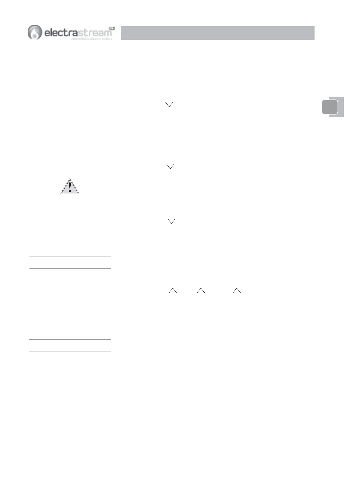
When the hot water within the cylinder is within 2° of the set (8) Target 65°C, only one
element will be on.
When the hot water within the cylinder is between 2° and 4°C below the set (8) Target
65°C, then two elements will be on.
When the hot water within the cylinder is below 6°C of the set (8) Target 65°C, then all
three elements will be on.
13
2-1 System Control
OPERAOPERA
OPERA
OPERAOPERA
TOR CONTROLS 2TOR CONTROLS 2
TOR CONTROLS 2
TOR CONTROLS 2TOR CONTROLS 2
Note
On twin coil systems the alternative heat
source supplements the electric.
22
2
22
UNVENTED CYLINDER
CYLINDER
TEMPERATURE SENSOR
& THERMAL CUT-OUT
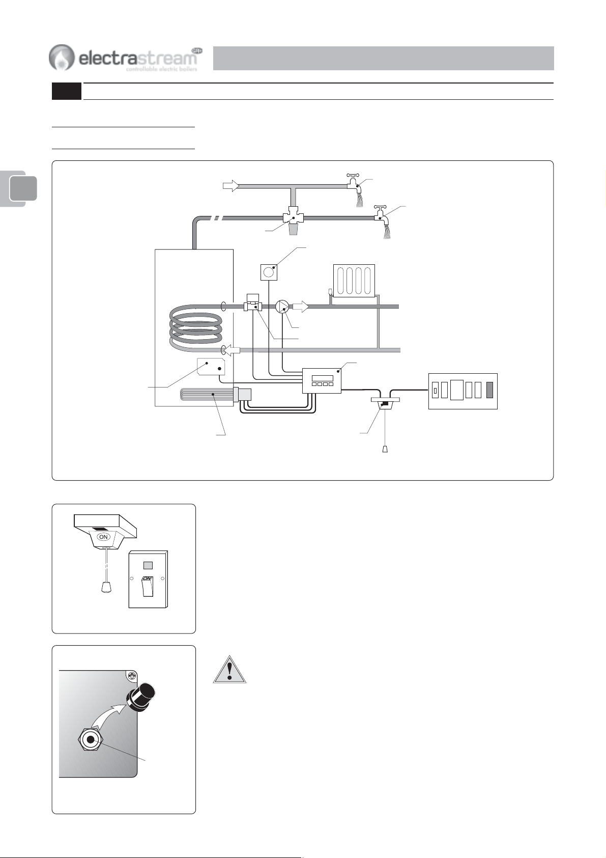
The heating and hot water system is all electric. The hot water for the taps (outlets) and
radiators is heated by the tri-core heater in the cylinder.
The system will have the following controls.
1
THERMOSTAIC
MIXING VALVE
ROOM THERMOSTAT
PUMP
MOTORISED VALVE
COLD WATER OUTLETS
ELECTRASTREAM
CONTROL UNIT
HOT WATER OUTLETS
CONSUMER UNIT
RC
TRI-CORE HEATER
Fig. 2-1b Isolating Switch
MANUAL RESET
BUTTON
Fig. 2-1c Thermal Cut-Out Thermostat
ISOLATING SWITCH
Fig. 2-1a Schematic of Typical Controls
2-1.1 Isolating Switch
The system will have a double pole isolating switch with neon and mechanical indicators.
This could be a pull cord or wall mounted type.
When the switch is ON (neon on) the system is operational.
When the switch is OFF (neon off) no hot water or heating will be available.
It is advised to turn the switch off when hot water and heating are not required, i.e.
holidays etc.
2-1.2 Electrastream Tri-core Heater
WARNING Unlike immersion heaters, the Electrastream tri-core heater
does not have an internal thermostat, therefore the cover should not need
to be removed.
When the cover is removed live electrical terminals are exposed.
ISOLATE THE TRI-CORE HEATER BEFORE REMOVING ITS COVER.
2-1.3 Over Temperature Cut-Out Thermostat
In the Electrastream temperature sensor box on the cylinder is the over temperature cutout thermostat. This prevents the water within the cylinder from overheating.
The over temperature cut-out thermostat is a manual reset type, this means it has a small
button that pops up when the thermostat has been tripped by overheating.
To reset the system after overheating, switch heating and hot water OFF, allow time for
the water to cool, or run off some hot water, then remove the cap and press the button.
14
OPERAOPERA
OPERA
OPERAOPERA
If the over temperature cut-out trips more than once, switch off the Electrastream
isolating switch and contact your installer.
2-1.4 Heating Motorised Valve
When the room thermostat is calling for heat and the Electrastream control unit is set for
heat ON, the heating motorised valve will open allowing water to the radiators.
TOR CONTROLS 2TOR CONTROLS 2
TOR CONTROLS 2
TOR CONTROLS 2TOR CONTROLS 2
IMPORTANT
When a programmable room
thermostat is used it should only be
set to call for heat when ‘Economy
Tariff’ is available.
Note
Refer to 2-2 for the Electrastream Control
Unit display and settings.
Display icon ‘Valve
2-1.5 Pump
The heating circulating pump is controlled by the Electrastream Control Unit in response
to the room thermostat.
The pump has 3 speeds, it is normally set to speed 2 (II). Consult the Electrastream
installer before changing this setting - see 4-4.3.
Display icon ‘Pump
2-1.6 Room Thermostat
The room thermostat controls the heat within the property.
When the room thermostat is calling for heat and the Electrastream control unit is set for
heat ON, the heating circulating pump will run, pumping water through the radiators.
Display icon ‘Therm ’ indicates the room thermostat is calling for heat.
2-1.7 Tri-core Heater Elements
The three elements heat the water in the cylinder when the Electrastream control unit is
programmed for a heat cycle. The elements are switched On and Off by the
Electrastream control unit in response to the temperature within the cylinder as detected
by the temperature sensor.
The elements have a staggered On sequence to prevent sudden loads - see 1-5.
’ indicates the valve is open.
’ indicates the pump is ON.
22
2
22
Note
Testing the RCD will not cause loss of the
Electrastream Control Unit settings.
Display icons ‘Heat 1 , Heat 2 , and Heat 3 indicate that the elements are
heating.
If either of the Heat icons are displaying an exclamation mark
an element - see 2-2.3.
2-1.8 Residual Current Device (RCD)
The Electrastream system will be protected by a Residual Current Device, this will
automatically switch Off the electric supply if an earth fault develops.
The RCD must be tested at least every three months, this is done by pressing the RCD
‘Test’ or ‘T’ button, this should switch the supply Off. Reset RCD to On after test.
If the RCD appears not to be working correctly contact your installer or a qualified
electrician.
2-1.9 Alternative Heat Source Controls
For twin coil systems the alternative heat source will have its own controls - refer to
manufacturers instructions.
The alternative heat source would normally be a cost effective method of heating the
cylinder and should be used and controlled for optimum performance thus reducing
heating costs.
‘!’ ‘!’
‘!’ this indicates a fault with
‘!’ ‘!’
15
OPERAOPERA
OPERA
OPERAOPERA
TOR CONTROLS 2TOR CONTROLS 2
TOR CONTROLS 2
TOR CONTROLS 2TOR CONTROLS 2
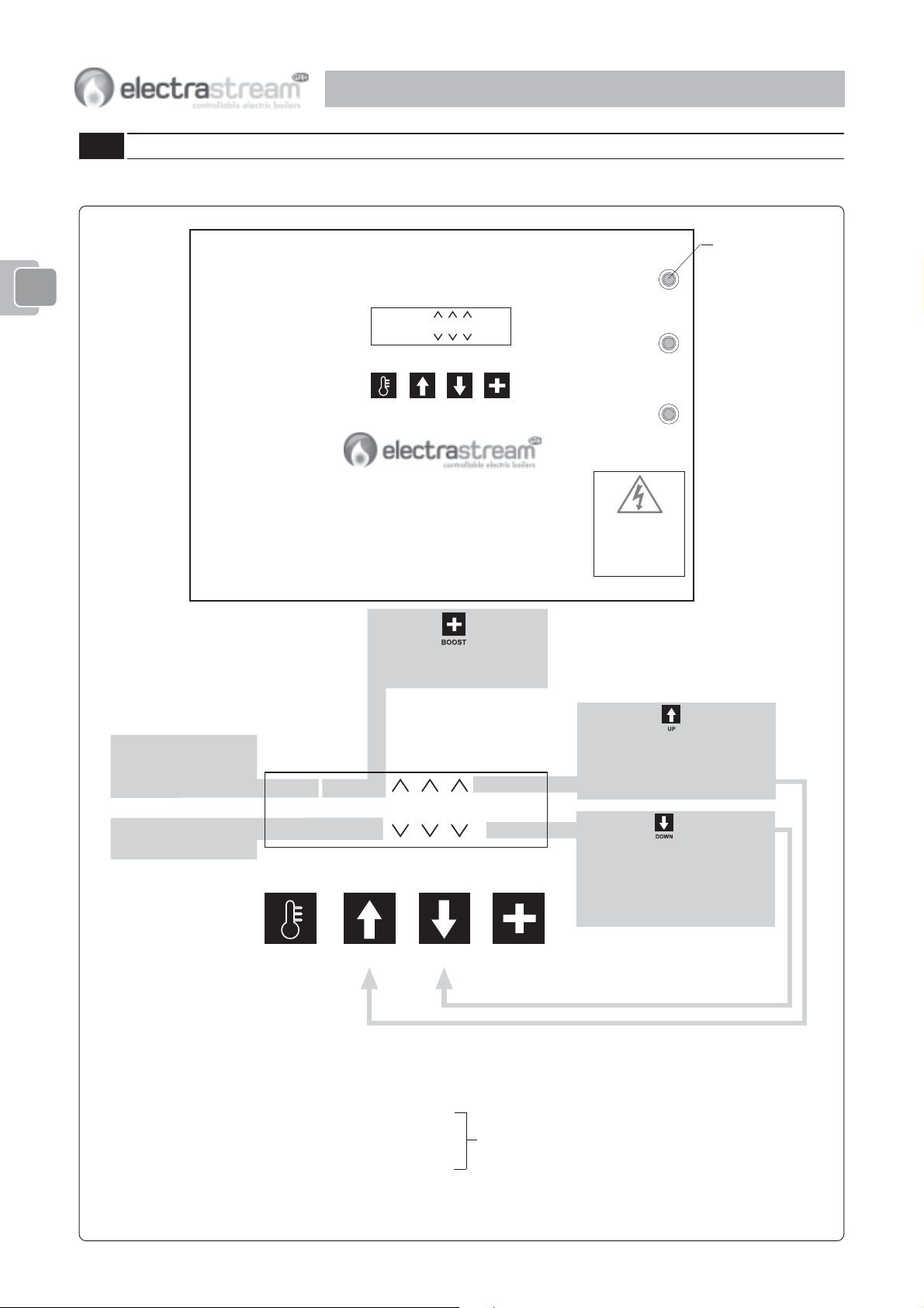
2-2 Electrastream Control Unit
2-2.1 Control Unit Display - Normal Screen
RESETTABLE THERMAL TRIPS
11
1
22
2
22
WATER TEMP
24°c Boost
Day hh:mm
HEAT 1
VALVE
HEAT 2
PUMP
HEAT 3
Auto/On/Off
THERM
MODE
HOT WATER
Auto/Off
HEATING
MODE
11
22
2
22
For display settings see 2-2.2
For error displays see 2-2.3
Displays actual water
temperature in cylinder
Set by (8) Target °c
Displays current Day
and Time (24 hr clock)
SET UP DOWN BOOST
ELECTRASTREAM
CONTROL
GAH HEATING PRODUCTS Ltd. 01394 421160
Toggled by
Boost displayed - Heating
On until next set OFF time
WATER TEMP
24°c Boost
HEAT 1
HEAT 2
HEAT 3
Auto/On/Off
Day hh:mm
THERM
PUMP
VALV E
MODE
HOT WATER
Auto/Off
HEATING
MODE
33
3
33
CAUTION
HIGH VOLTAGE!
DO NOT REMOVE ANY
COVERS (INCLUDING
ROOM THERMOSTAT)
BEFORE ISOLATING
THIS UNIT
Toggled by
Auto Timed
On Hot Water permanently ON
Off Hot Water permanently OFF
Toggled by
Auto Timed
Not available when HOT WATER MODE is Off
Off Heating Permanently OFF
Notes:- Select to turn heating off.
For Heating On use Boost.
16
SET DOWN BOOST
HEAT 1 Indicates Element 1 is ON HEAT 1
HEAT 2 Indicates Element 2 is ON HEAT 2
HEAT 3 Indicates Element 3 is ON HEAT 3
VALVE Indicates Heating Valve is OPEN
PUMP Indicates Heating Pump is ON
THERM Indicates Room Stat is calling for heat
>
>>
>>
>
>>
>>
>
>>
>>
>>
>>
>
>>
>>
>
>>
>>
>
UP
! !
! Indicates heater element has failed - see 2-2.4
! !
! !
! Indicates heater element has failed - see 2-2.4
! !
! !
! Indicates heater element has failed - see 2-2.4
! !
Heating on
TEST 1......5 Indicates heater test is being performed after midnight, this may take up to 30 minutes
Fig. 2-2a Electrastream Control Unit - Normal Screen
NORMAL SCREEN
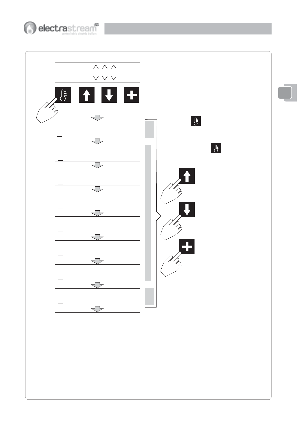
2-2.2 Display Time Settings
OPERAOPERA
OPERA
OPERAOPERA
TOR CONTROLS 2TOR CONTROLS 2
TOR CONTROLS 2
TOR CONTROLS 2TOR CONTROLS 2
24°c Boost
Day hh:mm
SET DOWN BOOST
UP
Auto/On/Off
Auto/Off
(1) Time
Day hh:mm
(2) Start 1
hh:mm
(3) Stop 1
hh:mm
(4) Start 2
hh:mm
22
2
22
When
DATE
TIME &
displayed for 10 seconds, display then reverts
back to normal screen
Repeat pressing
settings.
UP
SET is pressed, time settings are
SET to index through
Use to increment time up
Use to increment time down
(5) Stop 2
hh:mm
(6) Start 3
hh:mm
HEATING & HOT WATER
(7) Stop 3
hh:mm
(8) Target
65 °C
Hrs Run = 0000.1
0000.0 0000.0
Notes:All times are given in 24 hour clock.
Maximum cylinder temperature setting (Target °C) is 70°C.
TEMP.
WATER
Display only. Indicates the total hours that each tri-core
heater element has been in operation. (For service
engineers information only.)
DOWN
Use to select hours (hh:) or
minutes (:mm)
BOOST
For error displays see 2-2.3
Fig. 2-2b Electrastream Control Unit - Display Settings
17
 Loading...