

Electra Light CITY LED User Manual
CITY LED 96*10W-RGBW User’s Manual CITY LED 96*10W-RGBW User’s Manual
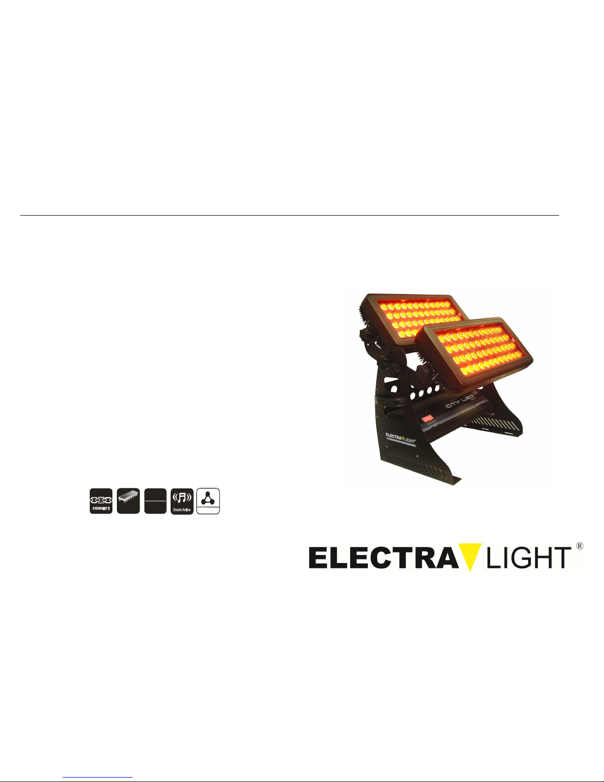
LED Washer Series
User’s Manual
AutoRun
DMX
512
PROGRAM
www.electralight.com.br
CITY LED 96*10W – RGBW – 4in1
User’s Manual
CITY LED 96*10W-RGBW User’s Manual CITY LED 96*10W-RGBW User’s Manual
SETUP AND OPERATION
Power Supply:
This fixture has an auto-switching power supply that can accommodate a wide range
of input voltages. But before plugging the units in, make sure that the source voltage
in your area matches the required voltage for your units. You should be sure that your
unit voltage matches the wall outlet voltage before attempting to operate your units.
DMX Cable Requirements:
The fixture can be controlled via standard DMX-512 protocol. It has 6 DMX channels
which can be set up on LED display panel. You need to use a standard 3-pin XLR
connector for data input and output If you are using your own cables, be sure to use
standard two conductor shielded cable. Your cables should be made with a male and
female XLR connector on either end of the cable. Also remember that DMX cable
must be daisy chained and cannot be split.
To ensure proper DMX data transmission, when using several DMX units, try to use
the shortest cable path. The order in which units are connected in a DMX chain does
not influent the DMX addressing. For example; a unit assigned a DMX address as 1
may be placed anywhere in a DMX line, at the beginning, or at the and, or anywhere
in the middle. When a unit is assigned a DMX address as 1, the DMX controller
understands to send DATA assigned to address 1 to that unit, no matter where it is
positioned in the DMX chain
Cabling the Fixtures
The fixtures need to be connected to each other with standard DMX data cables as
shown below: LED Washer SERIER User’s Manual
In DMX Controller mode, at the last fixture in the chain, the DMX output has to be
connected with a DMX terminator. This prevents electrical noise from disturbing and
corrupting the DMX control signals
The DMX terminator is simply an XLR connector with a 90 - 120Ω (ohm) 1/4 watt
resistor
Connected across pins 2 and 3 of a male XLR connector (DATA+ and DATA-). This
terminator is then plugged into the output socket on the last fixture in the daisy chain
to terminate the line Using a cable terminator will decrease the possibilities of erratic
behavior. The connections are illustrated below.
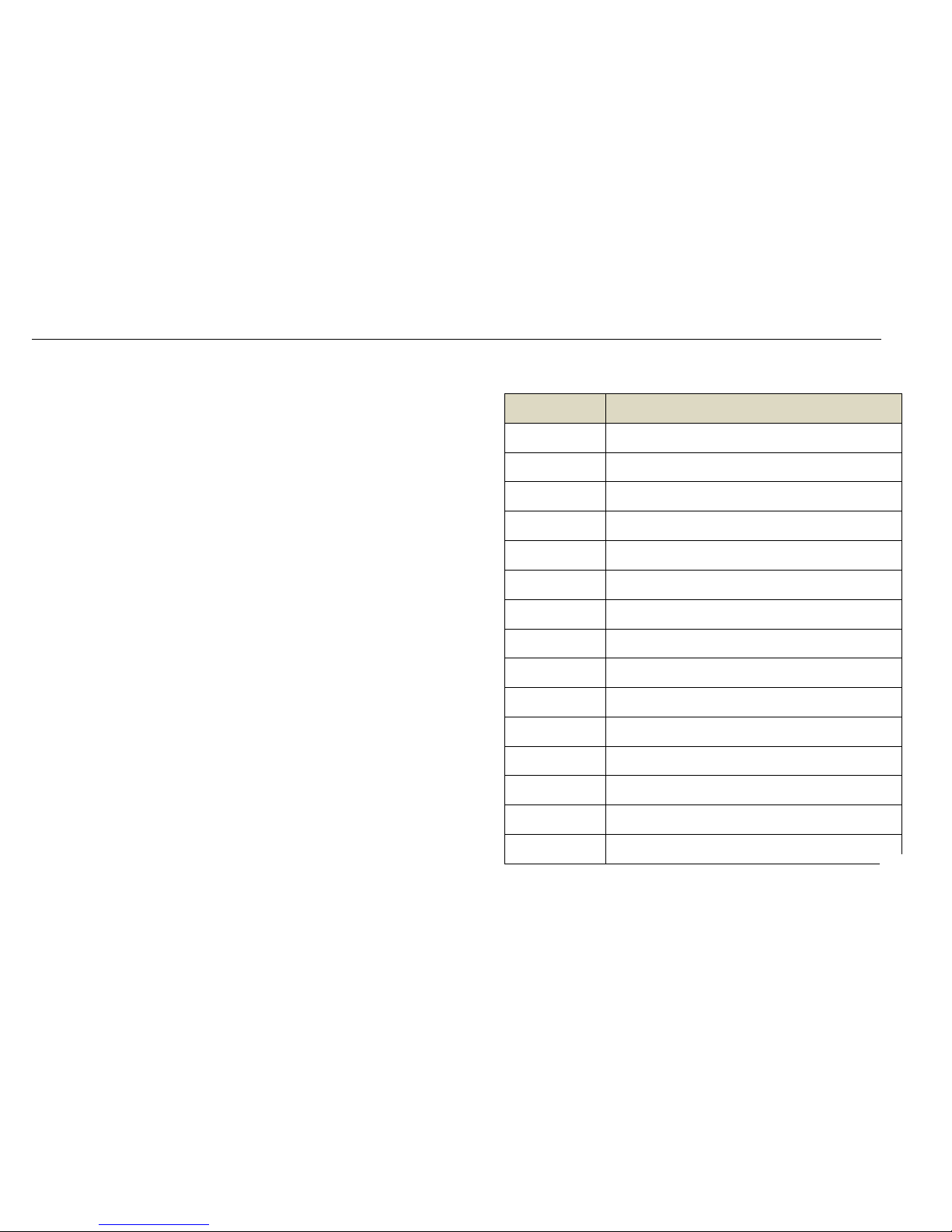
Memo
:
DATE REPAIR RECORD
.
2.
 Loading...