

elec-trace Cable Heating Floor System Installation Manual

Installation Manual
Cable Heating Floor System
P.O. BOX 333 St-Bruno, Québec, Canada
J3V 5G8
www.elec-trace.com info@elec-trace.com
1-866-994-4664

TABLE OF CONTENTS
Important safeguards and warnings 1
1 General information 2
1.1 Use of the manual 2
1.2 Safety guidelines 2
1.3 Remember to measure resistance 2
1.4 25-year limited warranty 3
2 Elec-Trace cable system 3
2.1 Cable specifications 3
2.2 Thermostat specifications 3
2.3 Typical installations and applications 4
3 Floor heating design and product selection 6
3.1 Design the installation 6
3.2 Confirm your product selection 8
4 Installation 9
5 Commissioning 14
5.1 Insulation resistance test 14
5.2 Heating cable resistance test 14
5.3 Sensor resistance test 15
6 Troubleshooting 15
LIMITED 25-YEAR WARRANTY 16

1
Important Safeguards and Warnings
WARNING: Shock and fire hazard
If the cable system is damaged or not installed properly, fire or shock could occur
resulting in serious personal injury or damage to property. You must carefully follow
the warnings and instructions contained in this manual.
• The Elec-Trace™ thermostat must be used.
• It is important that this equipment is installed only by qualified electricians who
are familiar with the proper sizing, installation, construction and operation of
floor warming systems and the hazards involved. The installation must comply
with all national and local electrical codes. If you are unfamiliar with these
requirements, contact an electrician.
• The heating cable is designed for under floor heating purposes only. Be sure
that the floor is not penetrated by nails, screws, or similar devices that can
cause damage on first installation or during subsequent floor repairs in the
future.
• If the cable system is damaged, it must be replaced. Do not attempt to splice
or repair any part of the system.
Important information
• First-time installers should call the Elec-Trace™ toll free number at
1-866-994-4664.
• Read the installation manual before installing the product. Install this electrical
product only according to manufacturer’s guidelines.
• The installation of the product shall be in accordance the Canadian Electrical
Code Part 1 or the National Electrical Code (US) where applicable.
• Perform the mandatory tests described in this guide and record results.
• This product must be installed only by a qualified installer.
• Heating cable must be at least 15 cm (6 in) away from any heat source.
• Install Elec-Trace™ above 5 degrees Celsius or 40 degrees Fahrenheit.
• The cable cannot be cut or overlapped
• Do not make any changes or alterations to the cable.
• Use only approved cable guides sold by Elec-Trace™ to secure the cable to
the sub-floor. Any substitution will void the warranty.
• A class A GFCI or GFCI circuit breaker must be installed.
• Install cables to a minimum of 3 or 4 inches apart.
• Do not install product if the safety seal on the box has been broken.
• Do not install on or in walls.
• The cable set must not extend beyond the room or area in which it originates.
• All of the heating cable including the connection joint must be covered with
self-leveling motar or thinset motar. See motar manufacturers’
recommendations for product installation over heating cable.
2
1 General Information
1.1 Use of the Manual
This manual describes the Elec-Trace™ floor heating system — how to design the
room, select the product, and install the system. It is important to thoroughly review
this manual and the Elec-Trace™ Thermostat Installation and Operation Manual
prior to installation.
1.2 Safety Guidelines
The safety and reliability of any floor heating system depends on proper design,
installation and testing. Incorrect installation or mishandling of the product can
cause damage to the heating cable, system components and property, and can
create a risk of fire or shock. The guidelines and instructions contained in this guide
are important. Follow them carefully to minimize these risks and to ensure that the
cable system performs reliably.
Pay special attention to the following:
• Instructions marked IMPORTANT
• Safety warnings identified as WARNING
1.3 Remember to Measure Resistance
The resistance should be measured between the two conductors: white and black
or red and black. Compare this resistance reading to the resistance specified on the
product tag. The value should be within ±10%. If you get a different reading, contact
Elec-Trace™ at 1-866-994-4664.
Also, measure the resistance between the white, black or red and shielding/ground
wire. Both should read infinity. If you get a different reading, contact Elec-Trace © at
1-866-994-4664. Please refer to Section 5 Commissioning for instructions on how
to measure the resistance.
IMPORTANT: Measure the resistance four times during the
Installation
Remember to always measure, verify and record the actual resistance throughout
the installation process (out of the box, after installation, after thinset motar or
self-leveler application, and after installation of final floor covering)
3
1.4 25-year Limited Warranty
For a period of 25 years, to the original owner and/or purchaser, Elec-Trace™
warrants that the heating cable will be free from defects in material, design and
workmanship. The extended warranty is only valid if the warranty certificate has
been properly completed and mailed, and the installation is in accordance with the
installation instructions.
2 Elec-Trace™ Cable System
2.1 Cable Specifications
2.2 Thermostat specifications
Cable construction: twin conductor
Rated voltage: 120V, 240V
Output: 3W/ft (9.84W/m) ±10%
Heating element size: 40 ft to 800 ft (12.2 to 243.8 m)
Bending radius: 1 in (25.4 mm)
Cable diameter: 1/8 to 1/6 in (3.2 to 4.2 mm)
Conductor insulation: fluoropolymer (Hytrel®)
Outer insulation: fluoropolymer or TPE or nylon
Max. ambient temp.: 85°F (30°C)
Min. installation temp.: 40°F (5°C)
Cold lead: 2-wire 16 AWG plus ground braid; 10 ft (3 m) length
Functions: On/off control, digital display, 7-day programmable
Supply voltage: 120/240 V ±15%, 50/60 Hz
Maximum switching current: 15 amps with GFIC
Temperature control range: 40 to 104°F (5 to 40°C)
Ambient range: 32 to 104°F (0 to 40°C)
Floor temperature sensor: 2-wire, 10-ft lead wire
4
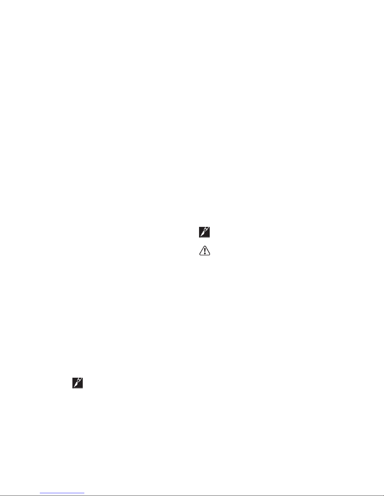
2.3 Typical Installations and Applications
DIRECTLY ON PLYWOOD:
Figure 1
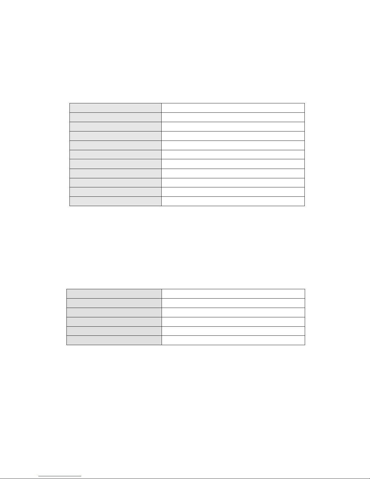
DIRECTLY ON CONCRETE:
Figure 2
ALTERNATIVE METHOD:
Self-leveling motar is recommended for large surfaces and the following floor
materials: engineered wood, laminate wood and some flexible materials (vinyl,
linoleum and carpets).
 Loading...