

Page 1
INSTRUCTION MANUAL
NSW Schools / TAFE - MB1250
Magnetic Panbrake (240V)
1300 x 1.6mm
K8303
Page 1
Instruction Manual for MB1250 (K8303)
01/12/2015
Page 2

# S5251 EB625 4/6/08
Page 2
Instruction Manual for MB1250 (K8303)
01/12/2015
# S5291 EB1000
# S5291 EB1250
ELECTRABRAKE
Electromagnetic sheetmetal bending machines
User Manual on the
EB 0625/1000/1250
Page 3

PAGE 1
Page 3
Instruction Manual for MB1250 (K8303)
01/12/2015
INTRODUCTION
ELECTRABRAKE machines use an electromagnet, rather than mechanical clamping. The
machine consists of a long electromagnet with a steel clamp bar located above it. The sheet
metal is clamped between the two surfaces by an electromagnet capable of clamping with a force
range of between 3 - 12 Tons. Rotating the bending beam then forms the bend. The sheet is bent
around the front edge of the clamp-bar.
Using the machine is simple, slide the sheet in under the clamp-bar; press the start-button to
initiate clamping; pull the handle to form the bend to the desired angle; and then return the handle
to automatically release the clamping force. The folded sheet can now be removed or
repositioned ready for another bend.
The special centre less compound hinges are distributed along the length of the bendi ng beam
allowing bending loads close to where they are generated.
The combined effect of the magnetic clamping with the special center less hinges means that the
ELECTRABRAKE is a very compact, space saving, machine with a very high strength-to-weight
ratio.
ELECTRABRAKE EB0625 EB1000 & EB1250
The ELECTRABRAKE EB0625, EB1000 & EB1250 are highly versatile sheet metal folding
machines used to bend mild steel and aluminium sheet metal. Thicknesses of up to 1.6 mm thick
can be folded across the full length of these machines. These multi-purpose machines bend
sheet metal of lengths 625mm, 1000mm and 1250mm respectively.
The ELECTRABRAKE magnetic clamping system replaces the bulky clamping structure used in
conventional folding machines. The small compact clamp bar does not hinder or obstruct the
work piece. Automatic electromagnetic clamping and unclamping, means faster operation. These
machines have much greater versatility than conventional sheet metal benders. The machines
are ideal for use in the sheet metal industry, air-conditioning and building industries.
An electrical interlock is offered to enhance Operator Safety. This operation ensures that a safe
pre-clamping force must be applied before full-clamping can be engaged.
ACCESSORIES
Adjustable backstops, storage tray and a complete set of short-length clamp-bars are included
as Standard Accessories.
A narrow clamp bar, a slotted clamp bar for forming shallow boxes more quickly and a power
shear with guide for straight distortion-free cutting of up to 1.6 mm thick is all available as
Optional Extra Accessories. A further optional extra is a foot switch which is available for
theEB1250 unit only.
A Full 12 month Warranty is offered that covers faulty materials and workmanship.
Page 4

ASSEMBLY
Page 4
Instruction Manual for MB1250 (K8303)
01/12/2015
HOW TO ASSEMBLE YOUR ELECTRABRAKE
Note: The machine is supplied upside down for assembly purposes.
1. Remove all parts from the crate with the exception of ELECTRABRAKE magnet body
assembly.
2. Find the 6mm Allen Key and fasteners supplied.
3. Use slings provided to remove the magnet body from the crate. Rest the body on wooden
blocks supplied.
4. Attach the feet to column
by using the M10 x 16 button-head screws provided. Point the
pair of feet forwards ensuring that the safety tape is facing forwards. Ensure that the
joining seam on the column faces to the backwards.
5. On Models EB0625 and EB1000, fasten foot plate under front feet using M10 by 16 caphead screws with washers. Alignment is easier if foot mounting is not tightened until the
foot plate is fitted. The rear feet cap head screws can be adjusted to level the machine.
A foot plate is not supplied with the EB1250 machine. The machine is bolted directly to
the floor at the front feet.
6. Place the ELECTRABRAKE magnet body on the stand securing it with M8 x 16 cap head
screws. This would be best if lifted with a lifting facility or some assistance. On Models
EB0625 and EB1000 ensure that connector and wires are g uided down the column as
the magnet body is lowered on to the stand.
7. On Models EB0625 and EB1000, connect the electromagnet to the electrical unit by
removing the rear access panel and plug the three pin connectors together. Refit access
panel.
8. On Model EB0625 using the M6 pan head screws and nuts, join the two halves of the
tray. Using M8 x 12 cap head screws attach tray to rear of machine. Fit rubber mat inside
tray. Attach backstop slides to the sides of tray. On Model EB1000 and EB1250, use two
M8 x 16 cap head screws to attach the two back stop bars. Slide the stop collars onto
each back stop bar. Fit rubber mat.
9. Using M8 x16 cap head screws attach the handle (s) to the bending beam. Before
attaching the handle on Models EB0625 and EB1000, slide it through the angle
indicating ring. On Model EB1250, slide stop collar to the top of the handle and tighten.
Fit the handle with angle scale to the right side.
10. On Model EB 1250 rotate the bending beam to 180 °. Slide angle indicator unit on to
right handle. Attach the two arms to the indicator spindle at the anchor block. To ensure
correct operation, securely fasten screws to switch mechanism.
11. Use solvent i.e. turpentine to remove the clear protective coating from the top of the unit
and from the clamp bar.
12. Place the clamp bar on the magnet body.
13. To obtain excellent results follow the operating instructions.
Page 2
Page 5
Page 3
Page 5
Instruction Manual for MB1250 (K8303)
01/12/2015
OPERATING PROCEDURES
GENERAL CAUTIONARY IMPORTANT WARNINGS
Electrabrake machines are designed for ONE operator only, which includes the inserting of the
sheet metal and operating the switches.
See specifications for clamping strength – please note that the force is several tonnes. All units
are fitted with a two-handed interlocking system to prevent hands being accidentally trapped
when clamping.
Safety procedures:
1. Safe pre-clamping is engaged
2. Full clamping is activated
3. Lower clamp bar to 5mm of the bed
4. Magnet will disengage
STANDARD BENDING
Preparation: Switch on power. Check that the clamp bar is correctly positioned.
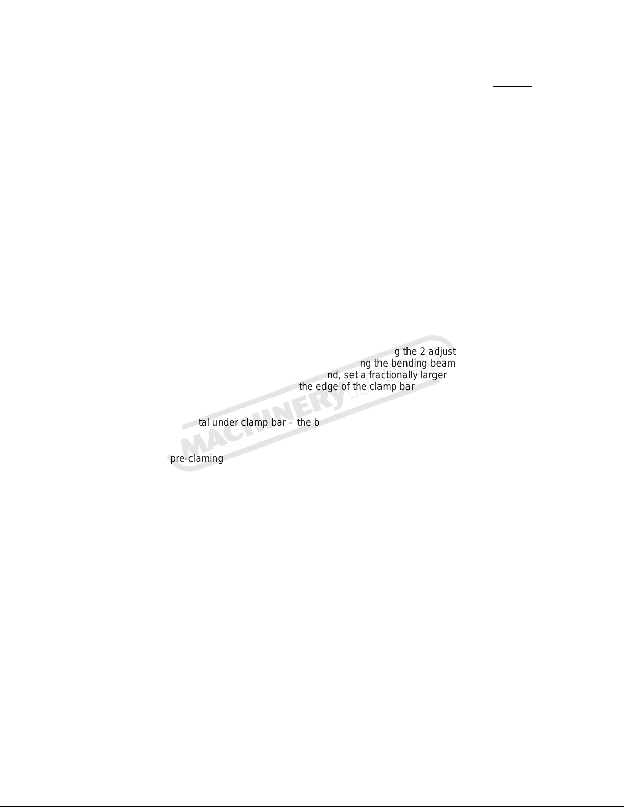
♦ Set the machine to suit the sheet metal thickness by rotating the 2 adjuster pins situated
on top of the clamp bar. Check the clearance by lifting the bending beam at 90 deg. and
examine the gap. To achieve and perfect bend, set a fractionally larger gap than the
thickness of the sheet metal between the edge of the clamp bar and the face of the
bending beam.
♦ Place sheet metal under clamp bar – the backstop can be used if needed.
♦ To apply pre-claming force use start button or the foot-switch to activate the magnet.
♦ To activate the micro-switch for full clamping, pull one of the bending handles with your
free hand. Release footswitch or start button.
♦ Pull on both handles and begin bending until the angle required is achieved. The right
handle has a angle scale, which graduates continuously. To allow for spring ba ck of the
sheet metal, bend a few degrees more than the angle that is required.
♦ The electrical circuit of the machine releases a reverse pulse as soon as the bending
beam starts its journey to the home position, allowing the clamp bar to release
immediately.
CAUTION
Do not insert small items under the clamp bar – a minimum lip bend of 15mm is required
except when bending very lightweight soft metal.
Page 6

Page 6
Instruction Manual for MB1250 (K8303)
01/12/2015
Page 4
To get the best performance do not clamp longer than is necessary due to the magnet having
less clamping force when heated.
HOW TO USE THE BACKSTOPS
Make use of the backstops when handling volume bends that are all the same size. Set the
backstops to the depth required.
Backstops can be used with a bar (not supplied) laid against them, making a long surface to
use as a reference.
Use a strip of sheet metal of the same thickness as the work piece if a backstop is required
under the clamp bar.
Page 7
Page 7
Instruction Manual for MB1250 (K8303)
01/12/2015
HOW TO FOLD A LIP
Folding the lip will depend on the sheet metal thickness and the length and width.
Lightweight sheet metal up to 0.8mm.
1. Carry out instruction for standard bending and continue to bend as far as possible.
2. Take away the clamp bar, leave the sheet metal on the machine and move 10mm
backwards, bring over the bending beam and compress the lip. No clamping is
required. Thick sheet metal is not suitable for this application.
3. Further flattening can be accomplished when using thin lightweight material by
following up with magnetic clamping
Page 5
Page 8
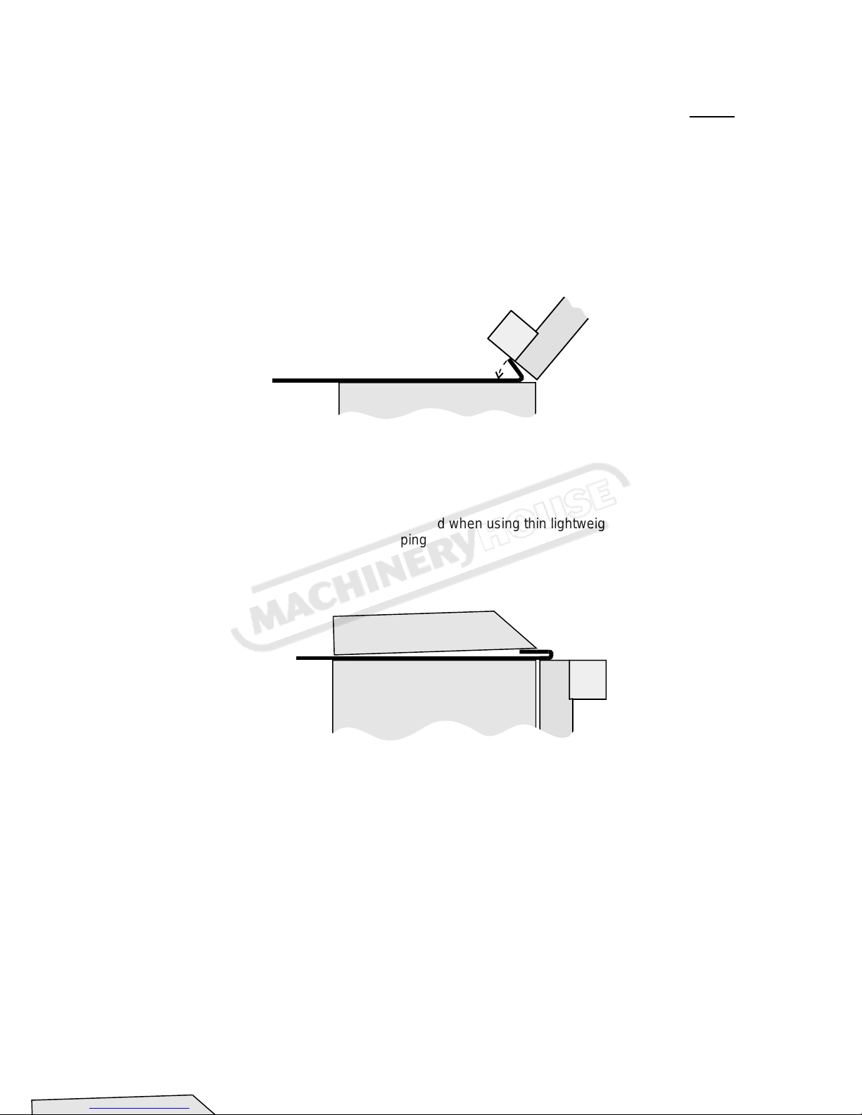
HOW TO MAKE A ROLLED EDGE
Page 8
Instruction Manual for MB1250 (K8303)
01/12/2015
Wrap sheet metal around a round steel bar or pipe.
1. Position sheet metal clamp bar and round pipe/bar as indicated on drawing.
i) To avoid weak clamping make sure that the clamp bar does not overlap the
machines front pole (A).
ii) Ensure that the rolling pipe is resting on the front pole of the machine (B). It
must not sit on the aluminium surface of the machine.
iii) The clamp bar provides a magnetic pathway (C) for the rolling bar.
2. Wrap the sheet metal around the rolling bar as far as possible –
3. Repeat step 2 until rolled edge is formed to required diameter.
Page 6
Page 9

Page 7
Page 9
Instruction Manual for MB1250 (K8303)
01/12/2015
HOW TO FORM A TEST PIECE
To learn how to work the Electrabrake with confidence it is recommended that test pieces are
made.
Use a piece of 0.8 mm thick x 320 x 200mm aluminium or mild steel sheet. Mark sheet as per
drawing
8
200
180°
Bend 1
45
95
117
190
90° reverse bend (mark this line on the
Bend 2
reverse side of the sheet)
Bend 3
90°
Bend 4 90°
90°
Bend 5
Form a lip on the edge of the sheet metal (see: How to form a lip)
Turn sheet metal over and insert under the clamp bar with the folded lip end toward you. Tilt
clamp bar and line up bend marked 2. Bend to 90 degrees as shown in drawing below.
335
This section to be rolled around Ø25mm
round bar
Turn sheet metal over and continue with steps marked 3, 4 and 5 bent to 90 degrees.
Roll the remaining piece around a 25 mm diameter round bar (see How to make a rolled edg e)
See drawing below for completed job.
Page 10

Page 8
Page 10
Instruction Manual for MB1250 (K8303)
01/12/2015
HOW TO MAKE A BOX USING SHORT CLAMP BARS
For ease of folding, make use of the short clamp bars which are able to be attached to each
other. Electrabrake is designed to assist you in the manufacture of a vast variety of box shapes.
BASIC BOXES
Use the long bar clamp to make the first two bends. Choose and insert one or two of the short
clamp bars as indicated on drawing.
Select the largest clamp piece for bends up to 70mm and for longer lengths use several clamp
pieces to fit the required length.
Clamp pieces can be plugged together for repeat bending when making a single unit. A slotted
clamp bar must be used for boxes or trays with shallow sides. Refer to HOW TO MAKE TRAYS.
LIPPED BOXES
1. Use the set of standard short clamp bars to make rectangular lipped boxes i.e. 98mm.
2. Choose the short clamp bar with at least a lip-width shorter than that of the box (Two or
three may be necessary – depending on length). Make folds 5, 6, 7 and 8. Take care to
guide the corner tabs on inside or outside of the box.
Page 11
Page 11
Instruction Manual for MB1250 (K8303)
01/12/2015
BOXES WITH INDIVIDUAL ENDS
Advantages:
Material saving
No corner notching
Cut without a guillotine
Fold with the regular full length clamp bar.
Disadvantages:
Extra folds to be carried out
Extra corners to join
The finished product shows more joins
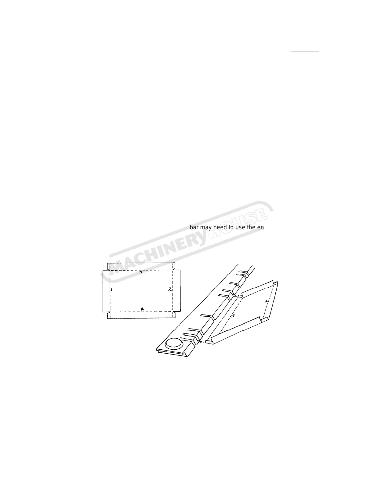
Use the full length clamp bar for all folding.
1. Set up sheet metal as per drawing below.
2. Form four folds in the sheet metal as shown on drawing.
3. For folds on side panels, as per drawing, use the narrow flange of the end piece of the
clamp bar
4. Join the box
Page 9
Page 12

Page 10
Page 12
Instruction Manual for MB1250 (K8303)
01/12/2015
FLANGED BOXES WITH PLAIN CORNERS
To make plain cornered boxes, the length and width should not exceed the clamp bar width of
98mm. Outside flanges are also used when making top hat sections.
1. Mark up sheet metal as per drawing below.
2. Use the full length clamp bar and fold sections marked 1, 2, 3 & 4.
3. Form fold 5 by inserting the flange under clamp bar follow by folding 6.
4. Using slotted clamp bar form folds 3, 4, 7 and 8.
Page 13

Page 11
Page 13
Instruction Manual for MB1250 (K8303)
01/12/2015
FLANGED BOX WITH CORNER TABS
Important Note: Folds must be formed in the correct sequence using one piece of sheet metal. It
is suggested the deep boxes are manufactured with separate end pieces.
1. Mark up sheet metal as be drawing below
2. Form all tab folds to 90deg. marked A at the one end of the full length clamp bar by
inserting the tab under the clamp bar.
3. Use the same end of the clamp bar and fold B to 45deg. Insert the side of the box instead
of the bottom under the clamp bar.
4. Form the flange fold C to 90deg, at the other end of the clamp bar.
5. Complete folds B to 90deg. By using suitable short clamp bars.
6. Complete the box by joining the corners.
Page 14
Page 12
Page 14
Instruction Manual for MB1250 (K8303)
01/12/2015
HOW TO USE A SLOTTED CLAMPBAR
FORMING TRAYS
The slotted clamp bar is perfect for manufacturing shallow trays and pans.
Advantages:
The Bending edges are aligned automatically to the front edge of the magnet body. The clamp
bar automatically lifts to facilitate insertion and removal of the sheet metal whereas with the short
set each section must be lifted individually.
The slotted clamp bar folds shallow trays, however trays of unlimited depth and complex shapes
can be manufactured with a short clamp bar.
The pitch of the slots has been calculated to enable the folding of various sizes of trays.
Specification sheet indicate shortest and longest tray sizes that can be accommodated by the
slotted clamp bar
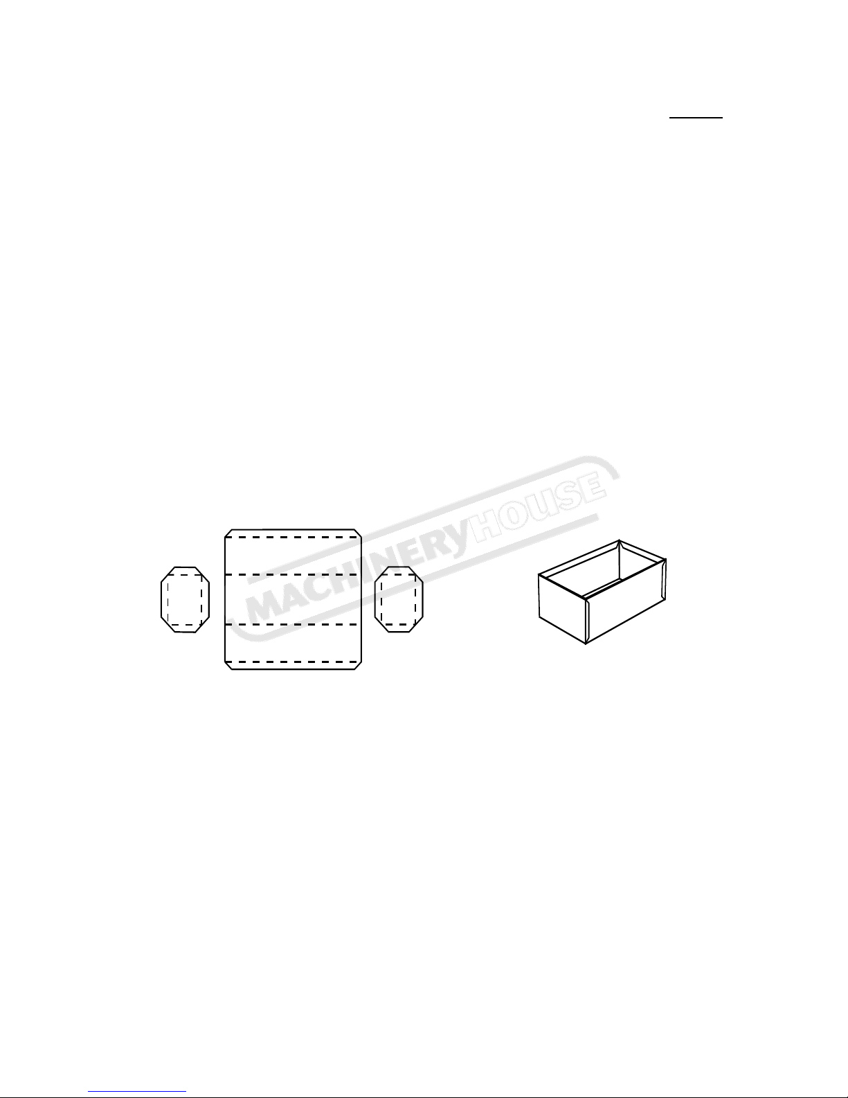
To fold shallow tray
1. First fold two opposite sides and the corner tabs by using the slotted clamp bar – ignore
the slots they will have no effect on the finished folds.
2. Select two slots to fold the remaining two sides. Line up the left side of the tray with the
left slot and check if there is a slot for the right side. Slide the tray along the left and try
the next slot until a suitable slot is found. The edge of the tray should be under the clamp
bar and between the two chosen slots.
3. To complete, fold the remaining sides.
Note: Trays that are almost as long as the clamp bar may need to use the end of the clamp bar
in lieu of a slot.
Page 15

Page 13
Page 15
Instruction Manual for MB1250 (K8303)
01/12/2015
HOW TO CHECK THE ACCURACY OF YOUR MACHINE
Critical aspects of Electrabrake are that working surfaces of the bending beam, the bending edge
clamp bar are straight and that both of these surfaces are parallel. This can be checked with a
precision straight edge.
How to check using the machine.
Swing bending beam up to 90deg. and hold or lock it in position with a back stop clamp collar at
the back of the angle slide on the handle. Check the gap between the working surface of the
bending beam and the edge of the clamp bar. Set the gap at 1mm on each side by using the
clamp bar adjusters. A feeler gauge or scrap piece of metal can be used.
The gap must be the same along the edge of the clamp bar. Variations can be wi thin +/-0.2mm.
the gap must not exceed 1.2mm and be less than 0.8mm. Should the adjustors not be the same
at each end, they will have to be reset – see Maintenance page 14.
Notes
The straightness of the elevated clamp bar is not important as this is flattened out in magnetic
clamping when in use.
The gap between the magnet body and bending beam is about 2 to 3mm. This does not affect the
bending accuracy.
Electrabrake produces folds on thinner gauges and non-ferrous metals such as aluminium,
however, check the specification for heavier gauges.
To fill in unused portion under the clamp bar, make use of scrap pieces of sheet metal to create
uniformity of the bends in thicker gauges.
Page 16

Page 14
Page 16
Instruction Manual for MB1250 (K8303)
01/12/2015
MAINTENANCE
ADJUSTERS
The adjuster rings on top of the clamp bar control the thickness of the sheet metal between the
bending beam and its edge.
Use these marks as a reference for repeat setting of the clamp bar. The bending gap will be
approx. 1mm if adjuster rings are both set so that the single pop mark is uppermost.
HINGE LUBRICATION
Grease all hinges once per month.
WORKING SURFACES
Bare working surface may become rusty or tarnished. Recondition by filling off and clean up
surfaces with emery paper. Use an anti-rust spray.
Page 17

Page 15
Page 17
Instruction Manual for MB1250 (K8303)
01/12/2015
TROUBLE SHOOTING
Prior to ordering a replacement electrical unit from the manufacturer please
check the following:
♦ If the machine does not operate at all, check the pilot light in the ON/OFF switch.
♦ If the machine is hot and power is available, leave the machine to cool and try again.
♦ Do not pull the handle prior to starting – the start button must be pressed first.
♦ If the bending beam is moved prior pressing the start button begin again and make sure
the handle is pushed fully back.
♦ Should the problem continue, the micro switch actuator may need to be adjusted.
♦ To check if the start button is faulty, try to start the machine with the foot switch.(if
provided)
♦ Check the connector and magnet at the electrical module.
♦ If the clamp bar snaps down on the release of the start button, this indicates that the 15
microfarad capacitor needs to be replaced.
♦ Should the machine cause blown fuses or trip your circuit breakers, it is likely that the
bridge rectifier is blown.
Full clamping not operating
If you are not achieving a full clamp, the angle micro switch may not be fully actuated.
How to check that the angle micro switch is being fully actuated.
♦ The micro switch can be found on the electrical panel located at the end of the square
brass section. The brass section is attached to the angle indicating mechanism.
♦ To access the electrical panel, the rear cover must be removed.
♦ When the bending beam is lifted this rotates the brass section which in turn depresses
the micro switch. You should be able to hear the micro switch click on and off.
♦ Failing this, adjust the clutching force. This can be done by ensuring that the two M8 cap
head screws at either end of the actuator shaft are secured.
♦ This adjustment should ensure that the actuator rotates and clutches however, if you are
still unable to hear the click, the micro switch may need adjusting.
♦ The actuator can be adjusted by loosening the screw that secures it, making the
adjustment, followed by re-tightening the screw.
Page 18

♦ If the micro switch does not click on and off after you have made the above adjustments
Page 18
Instruction Manual for MB1250 (K8303)
01/12/2015
and rotated the bending beam to the maximum stops, then the switch may be fused and
would need to be replaced. Call or email your distributor or Electrabrake.
Clamp bar not being released
♦ This is caused by the failure of the reverse pulse de-magnetising circuit.
♦ Check for sticky contacts on the relay and clean.
♦ The 6.8 power resistor or diodes could be faulty which will have to be replaced.
Problems with the bending of heavy gauge sheet metal.
♦ Ensure that sheet metal thickness is within the specifications of the machine.
♦ It may occur if narrow lips are being bent over the full length of the machine, please note
that the machine is not equipped to do this.
♦ Should the work piece not be level (i.e. have a welded seam or a joint) it may not be
possible to bend the work piece. Ensure that all spaces under the clamp bar are filled
with flat pieces of scrap metal.
Page 16
Page 19

CIRCUIT DIAGRAMS
Page 19
Instruction Manual for MB1250 (K8303)
01/12/2015
Page 17
Voltage Tests
AC DC
Reference point Any BLUE
wire
Test point
LIGHT-
Clamping
A B C D E
240
V ac
25
V ac
Condition
FULL-
Clamping
240
V ac
240
V ac
Condition
Any BLACK wire
+25
V dc
+215
V dc
+25
V dc
+215
V dc
-300
V dc
-340
V dc
Page 20

Page 18
Page 20
Instruction Manual for MB1250 (K8303)
01/12/2015
SPECIFICATION SHEET
Model EB0625 EB1000 EB1250 EB2000 EB2500 EB3200
Weight of Machine
Nominal Capacity (length x
thickness)
Clamping Force Tons
Electricity Supply
Duty Cycle %
Protection
Foot Switch
Bending-edge Length mm
Distance between Lifters mm
U-Channel bends, minimum
spacing
Closed channel, minimum
internal
Z-reverse bends, minimum
spacing
Kg 72 110 150 270 315 380
mm
0625
x1.6
1000 x
1.6
1250 x
1.6
2000 x
1.6
2500 x
1.6
3200 x
1.2
3 4.5 6 9 12 10
1 phase, 220/240vac, 10A 1 phase, 220/240vac, 15A
30
°C Thermal cut-out 70°C
No Optional Standard
670 1050 1300 2090 2590 3290
630 1010 1260 2028 2528 3228
mm
mm
mm
35** / 16* 36** / 18*
16*** 19*** 45***
99 x 27*** 114 x 22***
114 x
45***
Thickness Capacities, full length (material thickness can increase depending on the length of
bend)
…Mild steel mm 1.6** / 1.2*
…Aluminum (medium-
hard)
…Copper, Zinc, Brass
(medium-hard)
mm 1.6** / 1.2*
mm 1.6** / 1.2*
…Stainless steel mm 1.0** / 0.9*
1.2** /
1.0*
1.2** /
1.0*
1.2** /
1.0*
0.9** /
0.8*
*** with standard full length clamp bar **with bending beam extension bar *extension bar
removed
Bending dimensions.
19mm
19mm (min)
Unlimited
- 98mm (min) Standard Clampbar
- 49mm (min) Narrow Clampbar
19mm (min)
Refer to Ch art
Page 21

Page 21
Instruction Manual for MB1250 (K8303)
01/12/2015
DIMENSIONAL SPECIFICATIONS
Page 19
Page 22

Page 22
Instruction Manual for MB1250 (K8303)
01/12/2015
INSPECTION SHEET
SERIAL NUMBER: ________________________
DATE: ___________________________________
MODEL: _________________________________
CONNECTIONS
g - Measure the resist
Earthin
CLAMPBAR
Check the bending-edge for Straightness (max deviation = 0.25 mm)
Height of lift (with lifting balls in grove) (min 3 mm) ......................... _______ mm
Are lifting balls able to be compressed flush with surface? ............. YES/NO
With the bending beam at 90° and adjusters set at position 1 (one)
is the bending-edge 1 mm from and parallel
With the bending beam at 90°, can the clamp bar be adjusted
forward to touch
BENDING TEST
(Maximum specifications bend to 90°, at minimum supply voltage.)
Thickness of test piece .............. _____ mm Length of Bend _____ mm
Lip Width .................................. _____ mm Radius of Bend _____ mm
Uniformity of bend angle (maximum deviation = 2°) ....................... _____ deg
LABELS
Check for clar
Name Plate with serial number. . Clamp bar Warning ........
Electrical warnings ..................... Switch labelling ..............
Main ID label ..............................
Safety Tape on front legs ...........
FINISH
Free from rust, blemishes etc and machine is clean. ......................
ELECTRICAL INSOLATION
Test insolation from coil to magnet body .........................................
MIN/MAX SUPPLY VOLTAGE TESTS
At 260v: Pre-clamp.... ________ full-clamp.... _______ release…. _______
At 200v: Pre-clamp.... ________ full-c
Pre-clamp.... ________ full-clamp.... _______ release…. _______
INTERLOCK SEQUENCE
ith powe
W
Check that machine does NOT activate ........................................
ANGLE SCALE
Reading at edge of Indicator when bending beam is set
to 90° with an engineer's square. (Min 89°, max 91°) .................... ______ deg
the bending beam and adjusted back by 2 mm? .. YES/NO
ity, adhesion to machi
r on, pull HANDLE, then press START button.
ance from mains plug earth pin to magnet body _______ ohm
to the magnet-edge? . YES/NO
ne and proper alignment.
lamp… _______ release…. _______
_______ mm
Page 20
Page 23

Page 21
Page 23
Instruction Manual for MB1250 (K8303)
01/12/2015
MAGNET BODY
Straightness of top surface, along the length of machine
(Tolerance = ± 0.5 mm) ……….. ............................ ______ mm
Flatness of top surface, across the width of machines
(Tolerance = ± 0.1 mm) …………… ....................... ______ mm
FULL CLAMPING ACTIVATION DISTANCE
Distanc
measured at bottom of bending beam. (4 mm to 6 mm) ................ ______ mm
Reverse motion to switch-off machine. Measure back
from 90°. (Should be within the range 15° +
BENDING BEAM
Straightness of work
Alignment of extension bar (max deviation = ± 0.25 mm) ............... ______ mm
[Note: Test straightness with precision straight-edge.]
HINGES
Check for lubrication on shafts ... and sector blocks...........
Check that hinges rotate through 180° freely and smoothly ............
Check hinge pins do not rotate . and are “loctited” ...........
Have the retaining screw nuts been locked? ................................... YES/NO
e of movement of Bending Beam to a
ing surface (Tolerance = ± 0.25 mm) .............. ______ mm
ctivate full-clamping,
5°) ............................. ______ deg
SIGNATURES
Assembled & Tested .................. _____________________________________
Q. A. Inspection ......................... _____________________________________
Page 24

Page 22
Page 24
Instruction Manual for MB1250 (K8303)
01/12/2015
WARRANTY
Thank you for purchasing an Electrabrake Electromagnetic Sheet Metal Folding Machine. The
manufacturer warrants this Electrabrake folding machine to be free from defects in materials
and/or workmanship for a period of 12 months.
Our obligation under this Warranty is limited to repairing or replacing faulty parts or material s and
does not extend to consequential loss or damage arising from the use of the machine.
This Warranty does not cover faults that are due to misuse, abuse, negligence, accident or
caused during transportation. Also excluded are faults arising from unauthorised repair use not
according to instructions, and normal wear and tear.
Returns under Warranty must be freight-prepaid and, if the Warranty Registration has not been
previously returned, must be accompanied by proof of the purchase date.
The Warranty does not cover the costs of any repairs done by an unauthorised contractor of
these contractors unless prior arrangements have been made
Please fill in for your own reference:
Model _________ Serial No. __________ Date Purchased ___________
Dealer's Name and Address: ________________________________
________________________________
________________________________
________________________________
Before returning your machine for repair under warranty, please contact the Manufacturer to
discuss the most efficient means of transport and packaging and whether the whole or only a part
of the machine needs to be returned to the factory.
To establish proof of purchase date, please return the Warranty Registration on the following
page.
Page 25

Page 23
Page 25
Instruction Manual for MB1250 (K8303)
01/12/2015
WARRANTY REGISTRATION
Model No. ____________________ Serial No. ____________________
Date Purchased _______________
Dealer’s Name & Address:
_____________________________________
_____________________________________
_____________________________________
Customer's Name & Address:
_____________________________________
_____________________________________
_____________________________________
_____________________________________
After completing, please post this form to:
Electrabrake, PO Box 13043, Witfield, Gauteng 1467 South
Africa.
Fax (011) 823 3439
Page 26

ELECTRABRAKE EB 0625,EB 1000, EB 1250 PACKING LIST
Page 26
Instruction Manual for MB1250 (K8303)
01/12/2015
1. Main Electrabrake Assembly (with bending-beam Extension Bar fitted)
2. Main Full-length Clamp Bar
3. 1x Column
4. 4x Feet (2left &2right)
5. 2 x Handles (1 plain, 1 with angle scale) forEB 1250. 1x handle with angle
scale for EB0625&EB1000
6. 2x Backstop Bars for EB 1000&EB 1250
7. Angle Indicator Assembly
8. Tray + rubber mat
9. Fasteners, in packet with list. (including Stop Collars, 1 Allen key)
10. Clamp bar
11. Clamp bar 600mm (EB 1000&EB 1250)
12. Set of 6 Short Clamp bars
13. User Manual
 Loading...