

Page 1

EB2500
Magnetic Panbrake (240V)
2500 x 1.6mm
INSTRUCTION MANUAL
S5321
1
Instruction Manual for EB2500 (S5321)
24/8/2012
Page 2
2
C O N T E N T S
2
Instruction Manual for EB2500 (S5321)
24/8/2012
Page number
Introduction 3
Risk assessment 4 – 6
Pace maker warning 7
Assembling the EB0625, EB1000 8
Assembling the EB1250 9
Assembling the EB2000, EB2500, EB3200 10
Operating procedures for the EB2000, EB2500 and EB3200 11
General cautionary important warnings 11
Safety procedures: 11
Standard bending 11
How to use the backstops 12
How to fold a lip 12
How to make a rolled edge 13
How to form a test piece 14
Basic boxes 15
Lipped boxes 15
Boxes with individual ends 16
Flanged boxes with plain corners 16
Flanged box with corner tabs 17
How to use a slotted clamp bar 18
Forming trays 18
How to check the accuracy of your machine 19
How to check using th
Maintenance 20
Adjusters 20
Hinge lubrication 20
Working surfaces 20
Trouble shooting 20
Full clamping not operating 21
Clamp bar not being released 21
Problems with the bending of heavy gauge sheet metal. 22
EB 625 and EB1000 panel 23
EB 2000 EB3200 Wire panel 24
EB-0625 EB1250 Circuit diagram 25
EB 2000, EB2500 and EB3200 circuit diagram 26
Specification sheet 27
Dimensional specifications EB625 28
Dimensional specifications EB1000 28
Dimensional specifications EB1250 29
Dimensional specifications EB2000 30
Dimensional specifications EB2500 30
Dimensional specifications EB3200 31
Warranty 32
Warranty registration 33
ANEXURE 1
Basic Safety Precautions and Procedures: 34-35
FRAME ASSEMBLY AND PARTS LIST EB2000, EB2500, EB3200 36-37
e machine. 19
Packing Lists for EB 625 – EB 3200 38-43
Page 3
3
3
Instruction Manual for EB2500 (S5321)
24/8/2012
INTRODUCTION
ELECTRABRAKE machines use an electromagnet, rather than a mechanical, clamping system.
The machine consists of a long electromagnet with a steel clamp bar located above it. The sheet
metal is clamped between the two by an electromagnet capable of clamping with a force range of
between 3 - 10 Tons. Rotating the bending beam then forms the bend. The sheet is bent around
the front edge of the clamp-bar.
Using the machine is simple, slide the sheet in under the clamp-bar; press the start-button to
initiate clamping; lift the handle to form the bend to the desired angle; and then return the handle to
automatically release the clamping force. The folded sheet can now be removed or repositioned
ready for another bend.
The special centre less compound hinges, are distributed along the length of the bending beam
allowing bending loads close to where they are generated.
The combined effect of the magnetic clamping with the special centre less hinges means that the
ELECTRABRAKE is a very compact, space saving, machine with a very high strength-to-weight
ratio.
ELECTRABRAKE EB625, EB1000, EB1250, EB 2000, EB 2500 & EB3200
The ELECTRABRAKE EB625, EB1000, EB1250, EB2000, EB2500 & EB3200 are highly versatile
sheet metal folding machines used to bend mild steel and aluminium sheet metal. Thicknesses of
up to 1.2 mm thick can be folded on the EB3200, across the full length of the machine. The
EB625, EB1000, EB1250, EB2000 and EB2500 machines fold material of up 1.6mm thickness.
These multi-purpose machines bend sheet metal of lengths 625mm, 1000mm, 1250mm, 2000mm,
2500mm and 3200mm respectively.
The ELECTRABRAKE magnetic clamping system replaces the bulky clamping structure used in
conventional folding machines. The small compact clamp bar does not hinder or obstruct the work
piece. Automatic electromagnetic clamping and unclamping, means faster operation. These
machines have a much greater versatility than conventional sheet metal benders. The machines
are ideal for use in industry, air-conditioning and building industries.
For the EB-2000, EB2500 and EB3200 an electrical interlock is offered to enhance Operator
Safety. This operation ensures that a safe pre-clamping force must be applied before fullclamping can be engaged.
ACCESSORIES
Adjustable backstops, storage tray and a complete set of short-length clamp-bars are included as
Standard Accessories.
A foot switch is supplied as a standard accessory on the EB2000, EB2500 and EB3200 only. On
the EB1250 the foot switch is an optional extra.
A narrow clamp bar, a slotted clamp bar for forming shallow boxes more quickly and a power
shear with guide for straight distortion-free cutting of up to 1.6 mm thick is all available as Optional
Extra Accessories.
A Full 12 month warranty is offered that covers faulty materials and workmanship.
Page 4

4
4
Instruction Manual for EB2500 (S5321)
24/8/2012
Page 5

5
5
Instruction Manual for EB2500 (S5321)
24/8/2012
Page 6
6
6
Instruction Manual for EB2500 (S5321)
24/8/2012
Page 7
7
PACEMAKER PROTECTION
7
Instruction Manual for EB2500 (S5321)
24/8/2012
SAFETY PRECAUTIONS
Please note: no person with a pacemak
er should be closer than 6 FOOT OR 1.828 METRES to
an Electramagnetic machine or anything that has an electrical field.
1. Strong electromagnetic fields can cause electromagnetic interference.
2. EMI can stop the pacemaker from sensing your heart’s rhythm.
Page 8
8
8
Instruction Manual for EB2500 (S5321)
24/8/2012
ASSEMBLY
HOW TO ASSEMBLE YOUR ELECTRABRAKE
The EB625, EB1000
Note: The machine is supplied upside down for assembly purposes.
1. Remove all parts from the crate with the exception of ELECTRABRAKE magnet body
assembly.
2. Use the 6mm Allen Key and the screws supplied.
3. Place packing between the body and the crate.
4. Attach the feet to the column using the eight M10 x 16 button-head screws provided. Note
that the seam on the column is at the back and the two feet with the yellow and black safety
tape are the front feet.
5. Fasten the foot plate under the front feet using the M10 x 16 cap-head screws with washers.
Alignment is easier if the foot mounting is not tightened until the foot plate is fitted. The rear
feet cap head screws can be adjusted to level the machine.
6. Place the stand on its feet in a safe area so that the magnet body can be fastened to the
stand.
7. Place the magnet body on the stand securing it with two M8 x 16 cap head screws. This
would be best of you used a lifting device or got some assistance. Ensure that the magnet
wires are guided down the column as the magnet body is lowered onto the stand.
8. Remove the rear access cover to gain access to the electrical unit. By removing the four pan
head screws. Connect the adjoining matching plug leads from the magnetic coil and PC
board. Refit the rear access cover.
9. On the EB625 the tray is in two halves. First join the two halves of the tray using the two M6
pan head screws and nuts. Now using two M8 x 12 cap head screws attach the tray to the
back of the magnet body. Place the rubber mat in the tray. Attach the back stop slides to the
side of the tray.
10. On the EB1000 use four M8 x 12 cap head screws to attach the two back stop bars to the
back of the magnet body
11. On the EB1000 use three M8 x 12 cap head screws to attach the tray to the back of the
magnet body between the two back stop bars. Place the rubber mat in the tray.
12. Open the bending beam to gain access to the back of the bending beam so that you can
attach the handle.
13. Slide the handle through the angle indicating ring. Now using two M8 x 16 cap-head screws
to attach the handle to the bending beam.
14. Use solvent i.e. turpentine or methylated spirits to remove the clear protective coating from
the top of the unit and the clamp bar.
15. Place the clamp bar on the magnet body.
16. To obtain excellent results follow the operating instructions.
Page 9
9
9
Instruction Manual for EB2500 (S5321)
24/8/2012
ASSEMBLY
HOW TO ASSEMBLE YOUR ELECTRABRAKE
The EB1250
Note: The machine is supplied upside down for assembly purposes.
1. Remove all parts from the crate with the exception of ELECTRABRAKE magnet body
assembly.
2. Find the 6mm Allen Key and the screws supplied.
3. Lift the magnet body up from the crate. Place a plank between the body and the crate.
4. Attach the feet to the column using the eight M10 x 16 button-head screws provided. Note
that the seam on the column is at the back and the two feet with the yellow and black safety
tape are the front feet.
5. The rear feet cap head screws can be adjusted to level the machine.
6. Place the stand on its feet in a safe area so that the magnet body can be fastened to the
stand.
7. Place the magnet body on the stand securing it with two M8 x 16 cap head screws. This
would be best of you used a lifting device or got some assistance.
8. Use four M8 x 12 cap head screws to attach the two back stop bars to the back of the
magnet body
9. Use three M8 x 12 cap head screws to attach the tray to the back of the magnet body
between the two back stop bars. Place the rubber mat in the tray.
10. Open the bending beam to gain access to the back of the bending beam so that you can
attach the handle.
11. Use two M8 x 20 cap-head screws per handle to attach the handles to the bending beam.
12. The handle with the angle scale is attached on the left hand side of the bending beam.
Attach the other handle on the right hand side.
13. Slide the angle indicator unit onto the left handle. Attach the 2 arms to the indicator spindle.
To ensure correct operation securely fasten the screws to the switching mechanism.
14. Use the two M12 x 60 masonry bolts supplied to secure the Electrabrake machine to the
floor. Adjust the head levelling screws in the rear of each foot until the machine is stable and
level.
15. Use solvent i.e. turpentine or methylated spirits to remove the clear protective coating from
the top of the unit and the clamp bar.
16. Place the clamp bar on the magnet body.
17. To obtain excellent results follow the operating instructions.
Page 10

10
10
Instruction Manual for EB2500 (S5321)
24/8/2012
ASSEMBLY
HOW TO ASSEMBLE YOUR ELECTRABRAKE
The EB2000, EB2500, EB3200
Note: The machine is supplied upside down for assembly purposes.
1. Remove all parts from the crate with the exception of ELECTRABRAKE magnet body
assembly.
2. Find the 6mm Allen Key and the screws supplied.
3. Lift the magnet body up from the crate. Place a plank between the body and the crate.
4. Attach the columns to the magnet body by using four M8 x 16 cap-head screws per column.
Open-out the bending beam to gain access to insert the screws.
5. NB Check that the right and left columns are in the correct position with the foot mounting
holes facing to the outside.
6. Attach the feet to respective columns with the adjusting screws pointing backwards using
four M10 x 16 button-head screws per foot.
7. Place the machine the right way up. Assistance is required on the large units.
8. Use four M8 x 16 cap-head screws to attach shelf to the columns. Place the rubber mat in
the shelf.
9. Use three M8 x 12 cap-head screws to attach the tray to the magnet body. Place the rubber
mat in the tray.
10. Use two M8 x 12 screws per backstop to attach the four backstop bars to the back of the
magnet body.
11. Use one M8 x 20 cap-head screw with lock nut per lifter handle to attach lifter handles to the
back of the shaft located at the outside of the columns.
12. Open the bending beam to gain access to the back of the bending beam so that you can
attach the handles
13. Use two M8 x 20 cap-head screws per handle to attach the handles to the bending beam.
14. The handle with the angle scale is attached to the right of the bending beam. Attach the
other handle on the left hand side.
15. Slide the angle indicator unit onto the right handle. Attach the 2 arms to the indicator spindle.
To ensure correct operation securely fasten the screws to the switching mechanism.
16. Use the two M12 x 60 masonry bolts supplied to secure the Electrabrake machine to the
floor. Adjust the head levelling screws in the rear of each foot until the machine is stable and
level.
17. Use solvent i.e. turpentine or methylated spirits to remove the clear protective coating from
the top of the unit and the clamp bar.
18. Place the clamp bar on the magnet body. To engage the heads of the lifter pins push lifter
handle back and then pull the handle forward.
19. To obtain excellent results follow the operating instructions.
Page 11
11
OPERATING PROCEDURES
11
Instruction Manual for EB2500 (S5321)
24/8/2012
GENERAL CAUTIONARY IMPORTANT WARNINGS
Electrabrake machines are designed for ONE operator only, which includes the inserting the sheet
metal and operating the switches.
See specifications for clamping strength – please note that the force is several tonnes. All units are
fitted with a two-handed interlocking system to prevent hands being accidentally trapped when
clamping.
Safety procedures:
1. Safe pre-clamping is engaged
2. Full clamping is activated
3. Lower clamp bar to 5mm of the bed
4. Magnet will engage
STANDARD BENDING
Preparation: Switch on power. Check that the clamp bar is correctly positioned and that locating
pins are in place at each end of the clamp bar.
For bigger models EB-2000, EB-2500 and EB-3200
Should lifting pins be locked – locate handles below the machine, push hard back and release
forward to lift the clamp bar slightly.
Set the machine to suit the sheet metal thickness by rotating the 2 screws situated on the
back edge of the clamp bar. Check the clearance by lifting the bending beam at 90 deg. and
examine the gap. To achieve and perfect bend, set a fractionally larger gap, than the depth
of the sheet metal, between the edge of the clamp bar and the face of the bending beam.
Place sheet metal under clamp bar – the backstop can be used if needed.
Lift handles or push down the clamp bar onto the sheet metal. The machine will not turn ON
until the clamp bar is within 5mm above the surface bed due to the interlock. The interlock
can be operated by locking down the lifting system if the clamp bar is unable to be lowered
to 5mm. This can occur when sheet metal is buckled.
To apply pre-claming force use the foot-switch or depress and hold any of the green start
buttons.
To activate the micro-switch for full clamping, pull one of the bending handles with your free
hand. Release footswitch or start button.
Pull on both handles and begin bending till the angle required is achieved. Assistance will be
necessary when carrying out heavy duty bending. The right handle has a beam angle, which
graduates continuously. To allow for spring back of the sheet metal, bend a few degrees
more than the angle that is required.
The electrical circuit of the machine releases a reverse pulse at the OFF stage allowing the
clamp bar to release immediately.
Page 12
12
To release the sheet metal, flick the material upwards, which will lift the clamp bar to make
12
Instruction Manual for EB2500 (S5321)
24/8/2012
ready for the next bend. It may be necessary to lift the clamp bar by using one of the lifting
handles.
CAUTION
Do not insert small items under the clamp bar – a minimum bend of 15mm is essential except
when bending very lightweight soft metal. This will prevent damage to the clamp bar.
To get the best performance do not clamp longer than is necessary due to the magnet having
less clamping force when heated.
HOW TO USE THE BACKSTOPS
Make use of the backstops when handling volume bends that are all the same size. Set the
backstops at the size required.
Backstops can be used with a bar (not supplied) laid against them, making a long surface to
use as a reference. The extension pies from the bending beam could be used.
Use a strip of sheet metal of the same thickness as the work piece if a backstop is required
under the clamp bar.
HOW TO FOLD A LIP
Folding the lip will depend on the sheet metal thickness and the length and width.
Lightweight sheet metal up to 0.8mm.
1. Carry out instruction for standard bending and continue to bend as far as possible. Move
the angle stop collar up to the top of the handle, and tighten the Allen head screw to
keep it there.
2. Take away the clamp bar, leave the sheet metal on the machine and move 10mm
backwards, bring over the bending beam and compress the lip. No clamping is required.
Thick sheet metal is not suitable for this application.
3. Further flattening can be accomplished when using thin lightweight material by following
up with magnetic clamping
Page 13

13
13
Instruction Manual for EB2500 (S5321)
24/8/2012
HOW TO MAKE A ROLLED EDGE
Wrap sheet metal around a round steel bar or pipe.
1. Position sheet metal clamp bar and round pipe/bar as indicated on drawing.
i) To avoid weak clamping make sure that the clamp bar does not overlap the
machines front pole (A).
ii) Ensure that the rolling pipe is resting on the front pole of the machine (B). It must
not sit on the aluminium surface of the machine.
iii) The clamp bar provides a magnetic pathway © for the rolling bar.
Folding round a pipe
2. Wrap the sheet metal around the rolling bar as far as possible –
Page 14

14
3. Repeat step 2 until rolled edge to requirement.
200
8
45
95
117
190
335
Bend 2
Bend 4 90°
Bend 3 90°
Bend 1 180°
This section to be rolled around Ø25mm
round bar
90° reverse bend (mark this line on the
reverse side of the sheet)
Bend 5 90°
14
Instruction Manual for EB2500 (S5321)
24/8/2012
HOW TO FORM A TEST PIECE
To learn how to work the Electrabrake with confidence it is recommended that test pieces are
made.
Use a piece of 0.8 mm thick x 320 x 200mm aluminium or mild steel sheet. Mark sheet as per
drawing
Form a lip on the edge of the sheet metal (see ‘How to form a Lip)
Turn sheet metal over and insert under the clamp bar with the folded lip end toward you. Tilt clamp
bar and line up bend marked 2. Bend to 90 degrees as shown in drawing below.
Turn sheet metal over and continue with steps marked 3, 4 and 5 bent to 90 degrees.
Roll the remaining piece around a 25 mm diameter round bar (see How to make a rolled edge) See
drawing below for completed job.
Page 15

15
For ease of folding, make use of the short clamp bars to the shape folds into each other.
15
Instruction Manual for EB2500 (S5321)
24/8/2012
Electrabrake is designed to assist you in the manufacture of a vast variety of box shapes.
BASIC BOXES
Use the long bar clamp to make the first two bends. Choose and insert one or two of the short
clamp bars as indicated on drawing.
Fitting the short clamp bar
Select the largest clamp piece for bends up to 70mm and for longer lengths use several clamp
pieces to fit the required length.
Clamp pieces can be plugged together for repeat bending when making a single unit. A slotted
clamp bar must be used for boxes or trays with shallow sides. Refer to HOW TO
MAKE TRAYS.
LIPPED BOXES
1. Use the set of standard short clamp bars to make rectangular lipped boxes i.e. 98mm.
2. Choose the short clamp bar with at least a lip-width shorter than that of the box (Two or
three may be necessary – depending on length). Make folds 5, 6, 7 and 8. Take care to
guide the corner tabs on inside or outside of the box.
Page 16

16
16
Instruction Manual for EB2500 (S5321)
24/8/2012
BOXES WITH INDIVIDUAL ENDS
Advantages:
Material saving
No corner notching
Cut without a guillotine
Fold with the regular full length clamp bar.
Disadvantages:
Extra folds to be carried out
Extra corners to join
The finished product shows more joins
Use the full length clamp bar for all folding.
1. Set up sheet metal as per drawing below
2. Form four folds in the sheet metal as shown on drawing.
3. For folds on side panels, as per drawing, use the narrow flange of the end piece of the
clamp bar
4. Join the box
FLANGED BOXES WITH PLAIN CORNERS
To make plain cornered boxes, the length and width should not exceed the clamp bar width of
98mm. Outside flanges are also used when making top hat sections.
1. Mark up sheet metal as per drawing below.
2. Use the full length clamp bar and fold sections marked 1, 2, 3 & 4.
3. Form fold 5 by inserting the flange under clamp bar follow by folding 6.
Page 17

17
4. Using slotted clamp bar form folds 3, 4, 7 and 8.
17
Instruction Manual for EB2500 (S5321)
24/8/2012
FLANGED BOX WITH CORNER TABS
Important Note: Folds must be formed in the correct sequence using one piece of sheet metal. It is
suggested the deep boxes are manufactured with separate end pieces.
1. Mark up sheet metal as be drawing below
2. Form all tab folds to 90deg. marked A at the one end of the full length clamp bar by inserting
the tab under the clamp bar.
3. Use the same end of the clamp bar and fold B to 45deg. by inserting the side of the box
instead of the bottom of the box under the clamp bar.
4. Form the flange fold C to 90deg. at the other end of the clamp bar.
5. Complete folds B to 90deg. By using suitable short clamp bars.
6. Complete the box by joining the corners.
Page 18

18
18
Instruction Manual for EB2500 (S5321)
24/8/2012
HOW TO USE A SLOTTED CLAMPBAR
FORMING TRAYS
The slotted clamp bar is perfect for manufacturing shallow trays and pans.
Advantages:
The Bending edges are aligned automatically to the front edge of the magnet body. The clamp bar
automatically lifts to facilitate insertion and removal of the sheet metal whereas with the short set
each section must be lifted individually.
The slotted clamp bar folds shallow trays, however trays of unlimited depth and complex shapes
can be manufactured with a short clamp bar.
The pitch of the slots has been calculated to enable the folding of various sizes of trays.
Specification sheet indicate shortest and longest tray sizes that can be accommodated by the
slotted clamp bar
To fold shallow tray
1. First fold two opposite sides and the corner tabs by using the slotted clamp bar – ignore the
slots they will have no effect on the finished folds.
2. Select two slots to fold the remaining two sides. Line up the left side of the tray with the left
slot and check if there is a slot for the right side. Slide the tray along the left and try the next
slot until a suitable slot is found. The edge of the tray should be under the clamp bar and
between the two chosen slots.
3. To complete, fold the remaining sides.
Note: Trays that are almost as long as the clamp bar may need to use the end of the clamp bar in
lieu of a slot.
Page 19
19
19
Instruction Manual for EB2500 (S5321)
24/8/2012
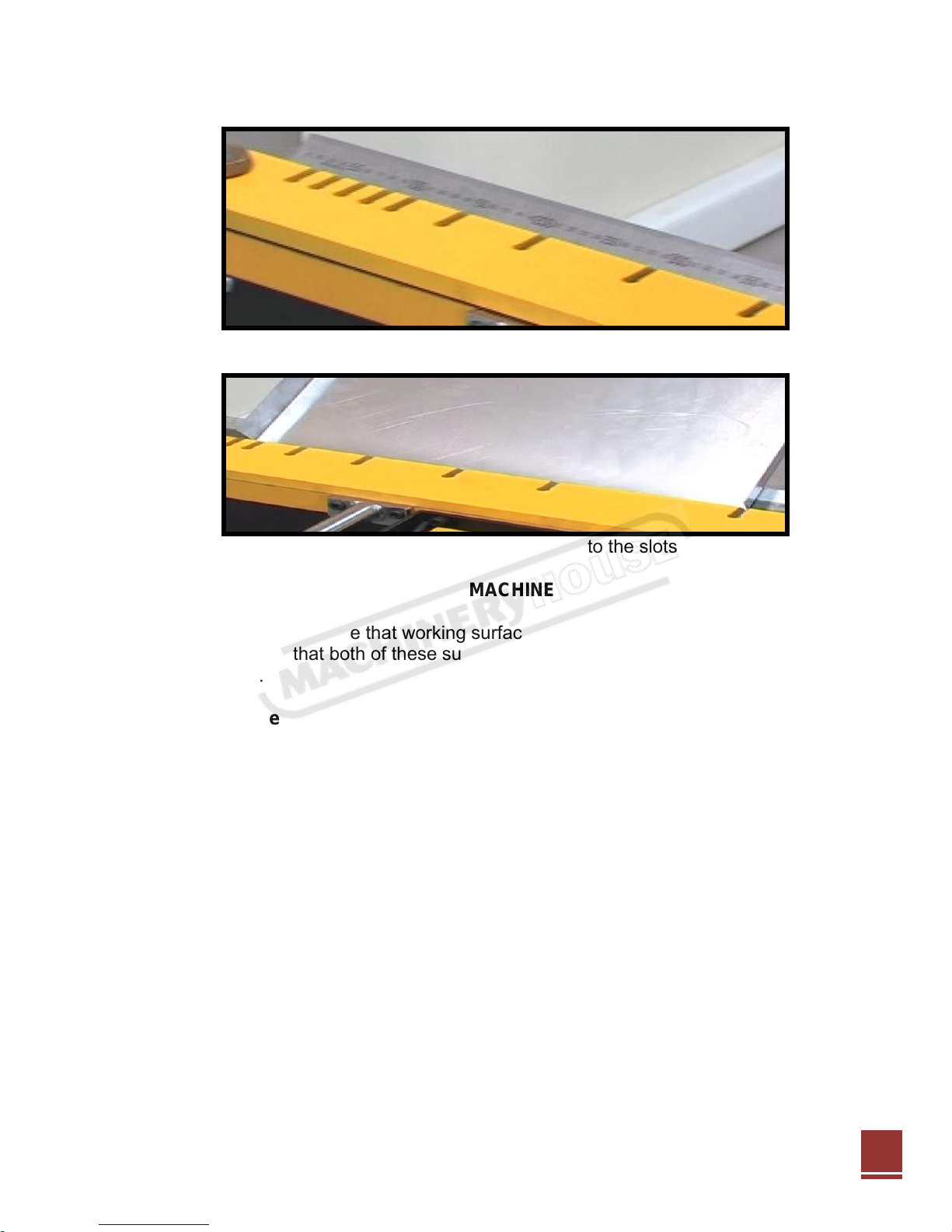
Measuring the slotted clamp bar
Folding a tray note that the folded sides fit into the slots
HOW TO CHECK THE ACCURACY OF YOUR MACHINE
Critical aspects of Electrabrake are that working surfaces of the bending beam, the bending edge
clamp bar are straight and that both of these surfaces are parallel. This can be checked with a
precision straight edge.
How to check using the machine.
Swing bending beam up to 90deg. and hold or lock it in position with a back stop clamp collar at
the back of the angle slide on the handle. Check the gap between the working surface of the
bending beam and the edge of the clamp bar. Set the gap at 1mm on each side by using the clamp
bar adjusters. A feeler gauge or scrap piece of metal can be used.
The gap must be the same along the edge of the clamp bar. Variations can be within +/-0.2mm.
The gap must not exceed 1.2mm and be less than 0.8mm. Should the adjustors not be the same at
each end, they will have to be reset – see Maintenance page 16.
Notes
The straightness of the elevated clamp bar is not important as this is flattened out in magnetic
clamping when in use.
The gap between the magnet body and bending beam is about 2 to 3mm. This does not affect the
bending accuracy.
Page 20

20
Electrabrake produces folds on thinner gauges and non-ferrous metals such as aluminium,
20
Instruction Manual for EB2500 (S5321)
24/8/2012
however, check the specification for heavier gauges.
To fill in unused portion under the clamp bar, make use of scrap pieces of sheet metal to create
uniformity of the bends in thicker gauges.
MAINTENANCE
ADJUSTERS
The adjuster screws at the end of the clamp bar control the thickness of the sheet metal between
the bending beam and its edge.
The heads for the screws are divided into 3 by centre pop marks. Use these marks as a reference
for repeat setting of the clamp bar. The bending gap will be approx. 1mm if adjuster screws are
both set so that the single pop mark is uppermost.
Adjuster set to 1mm
HINGE LUBRICATION
Grease all hinges once per month .
Hinge
WORKING SURFACES
Bare working surface may become rusty or tarnished. Recondition by filling off and clean up
surfaces with emery paper. Use an anti-rust spray.
TROUBLE SHOOTING
Prior to ordering a replacement electrical unit from the manufacturer please check the
following:
If the machine does not operate at all, check the pilot light in the ON/OFF switch.
If the machine is hot and power is available, leave the machine to cool and try again.
Do not pull the handle prior to starting – the start button must be pressed first.
If the bending beam is moved prior pressing the start button begin again and make sure the
handle is pushed fully back.
Page 21

21
Should the problem continue the micro switch actuator may need to be adjusted?
21
Instruction Manual for EB2500 (S5321)
24/8/2012
To check if the start button is faulty, try to start the machine with the foot switch.
Check the connector and magnet at the electrical module.
If the clamp bar snaps down on the release of the start button, this indicates that the 15
microfarad capacitor needs to be replaced.
Should the machine cause blown fuses or trip your circuit breakers, it is likely that the bridge
rectifier is blown.
Full clamping not operating
If you are not achieving a full clamp, the angle micro switch may not be fully actuated.
How to check that the angle micro switch is being fully actuated.
The micro switch can be found on the electrical panel located at the end of the square brass
section. The brass section is attached to the angle indicating mechanism.
To access the electrical panel, the rear cover must be removed.
When the bending beam is lifted this rotates the brass section which in turn depresses the
micro switch. You should be able to hear the micro switch click on and off.
Failing this, adjust the clutching force. This can be done by ensuring that the two M8 cap
head screws at either end of the actuator shaft are secured.
This adjustment should ensure that the actuator rotates and clutches however, if you are still
unable to hear the click, the micro switch may need adjusting.
The actuator can be adjusted by loosening the screw that secures it, making the adjustment,
followed by re-tightening the screw.
If the micro switch does not click on and off after you have made the above adjustments and
rotated the bending beam to the maximum stops, then the switch may be fused and would
need to be replaced. Call or email your distributor or Electrabrake.
Clamp bar not being released
This is caused by the failure of the reverse pulse de-magnetising circuit.
Check for sticky contacts on the relay and clean.
The 6.8 power resistor or diodes could faulty which will have to be replaced.
Page 22

22
Problems with the bending of heavy gauge sheet metal.
22
Instruction Manual for EB2500 (S5321)
24/8/2012
Ensure that sheet metal thickness is within the specifications of the machine.
It may occur if narrow lips are being bent over the full length of the machine, please note
that the machine is not equipped to do this.
Should the work piece not be level (i.e. have a welded seam or a joint) it may not be
possible to bend the work piece. Ensure that all spaces under the clamp bar are filled with
flat pieces of scrap metal.
Page 23

23
23
Instruction Manual for EB2500 (S5321)
24/8/2012
EB0625 AND EB1000 PANEL
Page 24

24
24
Instruction Manual for EB2500 (S5321)
24/8/2012
EB 2000 TO 3200 WIRE PANEL
Page 25

25
25
Instruction Manual for EB2500 (S5321)
24/8/2012
EB 0625 1250 CIRCUIT
Page 26
26
26
Instruction Manual for EB2500 (S5321)
24/8/2012
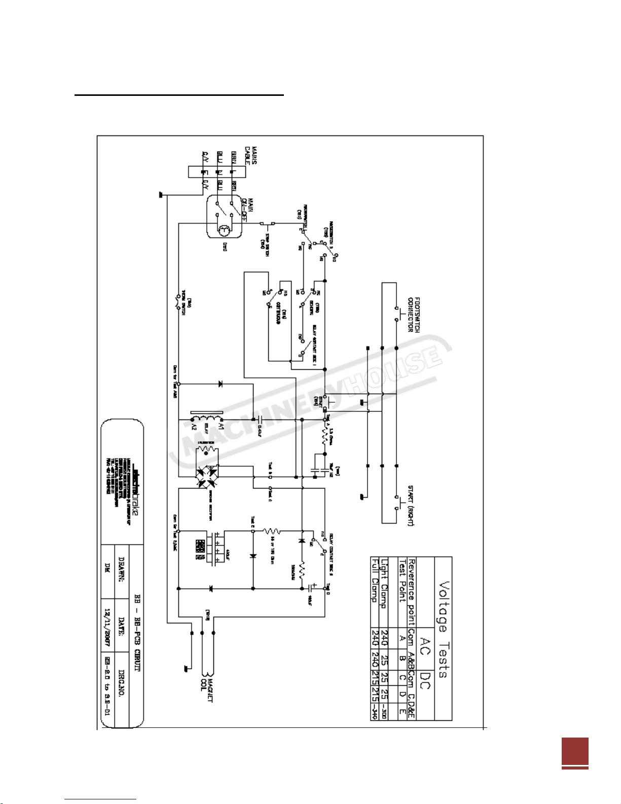
EB 2000-EB3200 CIRCUIT DIAGRAM
Page 27

27
SPECIFICATION SHEET
Model
EB0625
EB1000
EB1250
EB2000
EB2500
EB3200
Weight of Machine
Kg
72
110
150
270
315
380
Nominal Capacity (length
x thickness)
mm
0625
x1.6
1000 x
1.6
1250 x
1.6
2000 x
1.6
2500 x
1.6
3200 x
1.2
Clamping Force
Tons 3 4.5 6 9
12
10
Electricity Supply
1 phase, 220/240vac, 10A
1 phase, 220/240vac, 16A
Duty Cycle
%
30
Protection
°C
Thermal cut-out 70°/80°C
Foot Switch
No
Standard
Bending-edge Length
mm
670
1050
1300
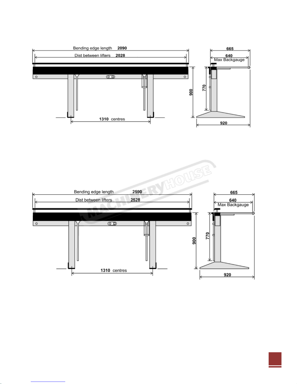
2090
2590
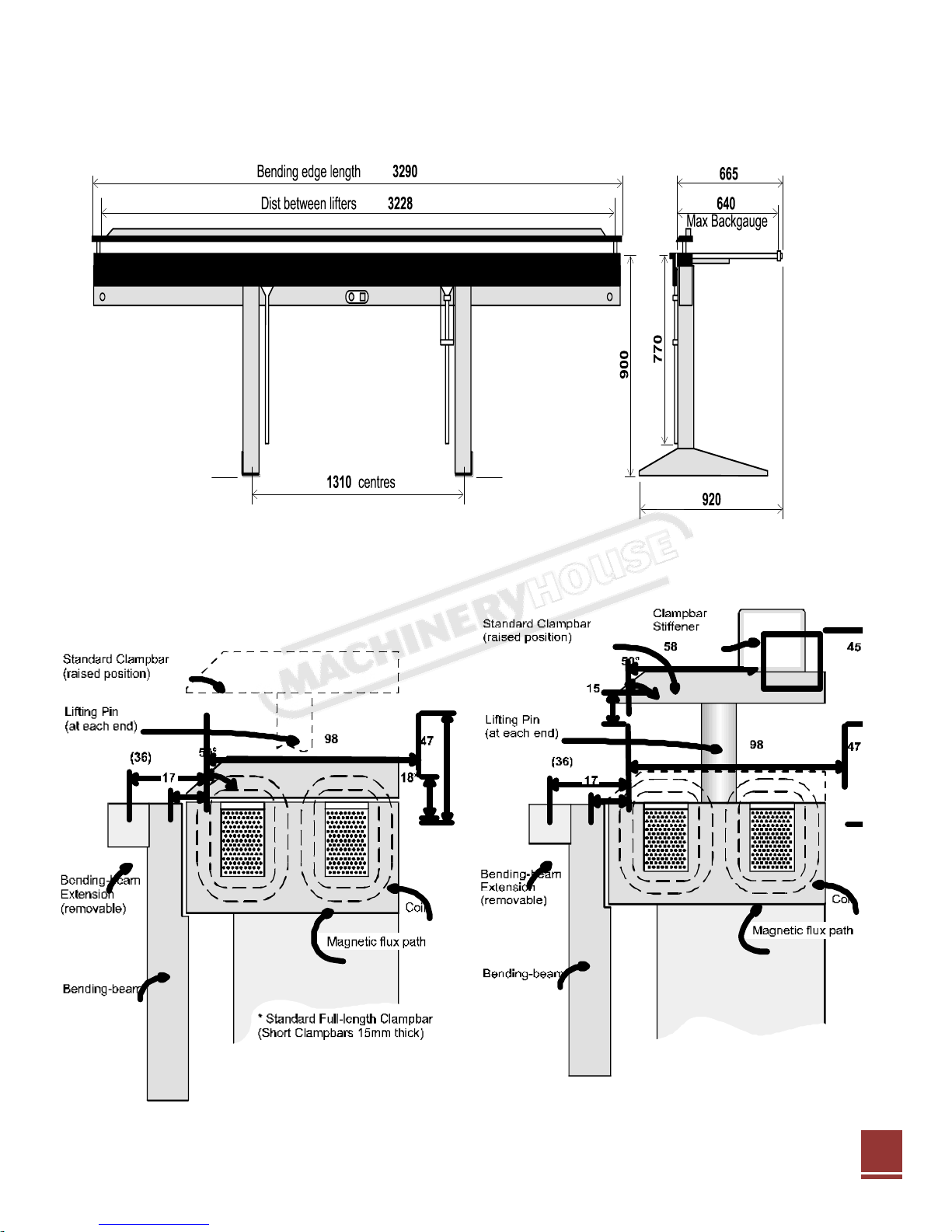
3290
Distance between Lifters
mm
630
1010
1260
2028
2528
3228
U-Channel bends,
minimum spacing
mm
16***
19***
45***
Closed channel, minimum
internal
mm
99 x 27***
114 x 22***
114 x
45***
Z-reverse bends, minimum
spacing
mm
35** / 16*
36** / 18*
Thickness Capacities, full length (material thickness can increase depending on the length of bend)
…Mild steel
mm
1.6** / 1.2*
1.2** /
1.0*
…Aluminium (medium-
hard)
mm
1.6** / 1.2*
1.2** /
1.0*
…Copper, Zinc, Brass
(medium-hard)
mm
1.6** / 1.2*
1.2** /
1.0*
…Stainless steel
mm
1.0** / 0.9*
0.9** /
0.8*
*** with standard full length clamp bar **with bending beam extension bar *extension bar
removed
Refer to Chart
19mm
19mm (min)
- 98mm (min) Standard Clampbar
- 49mm (min) Narrow Clampbar
19mm (min)
Unlimited
27
Instruction Manual for EB2500 (S5321)
24/8/2012
Bending dimensions.
Page 28
28
DIMENSIONAL SPECIFICATIONS EB625
28
Instruction Manual for EB2500 (S5321)
24/8/2012
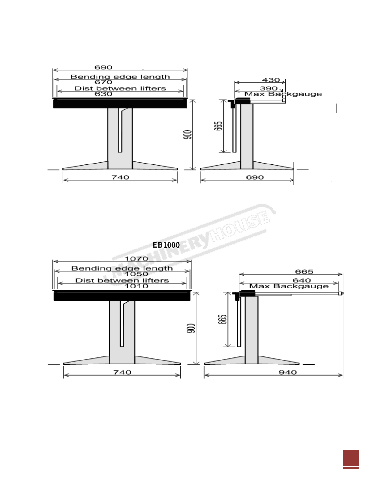
DIMENSIONAL SPECIFICATIONS EB1000
Page 29
29
DIMENSIONAL SPECIFICATIONS EB1250
29
Instruction Manual for EB2500 (S5321)
24/8/2012
Page 30
30
DIMENSIONAL SPECIFICATIONS EB2000
30
Instruction Manual for EB2500 (S5321)
24/8/2012
DIMENSIONAL SPECIFICATIONS EB2500
Page 31
31
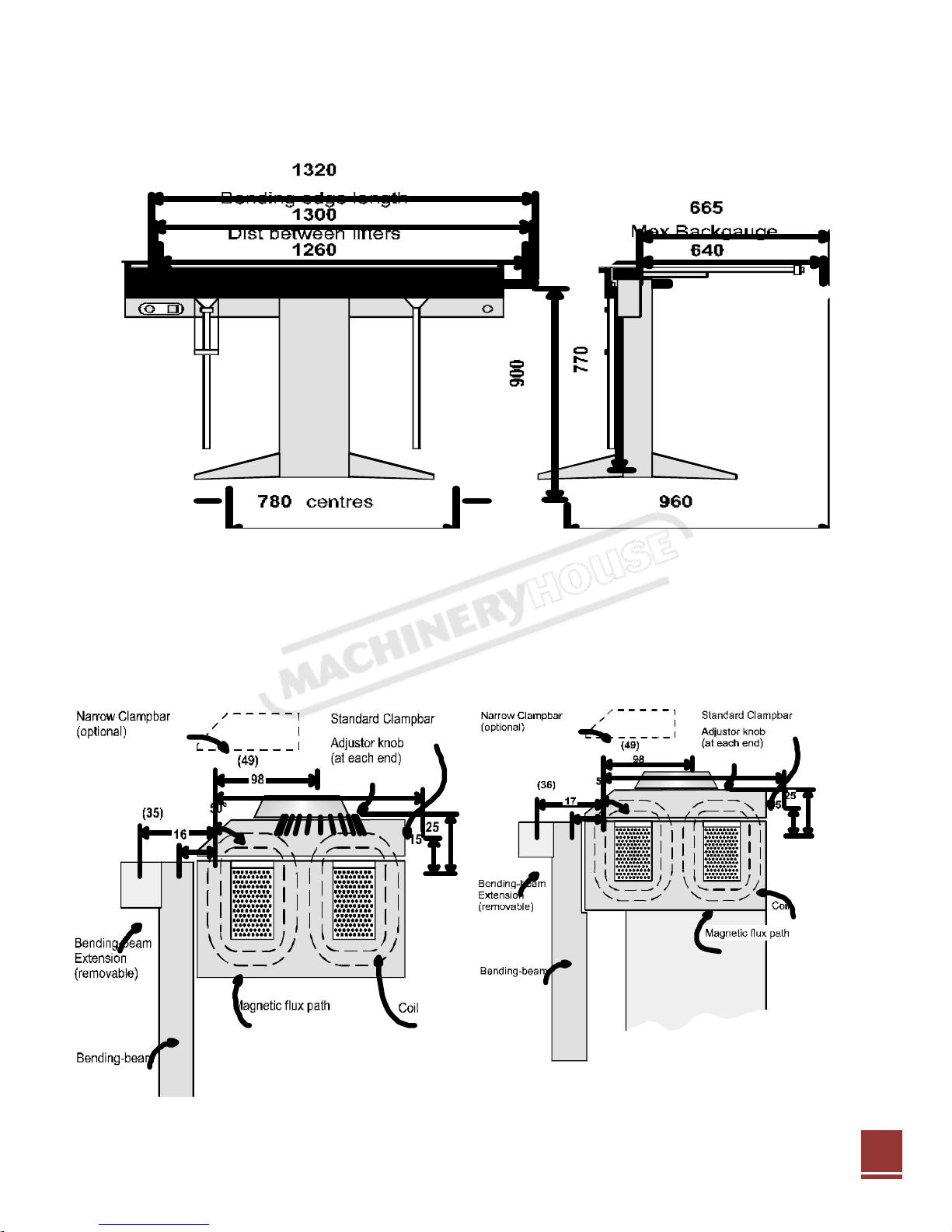
DIMENSIONAL SPECIFICATIONS EB3200
31
Instruction Manual for EB2500 (S5321)
24/8/2012
Page 32

34
ANNEXURE 1
32
Instruction Manual for EB2500 (S5321)
24/8/2012
Basic Safety Precautions and Procedures:
Safety is all about preventing accidents. Personal injury typically occurs because safety precautions are
either not learned, or they are not practiced. The following information is intended to assist you with some
basic safety procedures and precautions to help ensure your safety when operating and servicing your
ELECTRABRAKE machine.
If you cannot operate basic tools, you should not attempt to maintain or repair your ELECTRABRAKE
machine. Contact the Manufacturer or Sales Agent if any repair or maintenance procedure is not
understood.
Keep a first aid kit near by. Be aware of and know how to use the contents of the first aid kit. It is also a
good idea to have a fire extinguisher handy just in case of an emergency.
SAFETY PROCEDURES:
Individual, electrical, machines, and operating safety precautions are relatively similar for all of the major
categories. Make sure to pay close attention to any and all safety cautions and warnings posted on the
appliance being operated or serviced. Understanding and adhering to these safety tips can greatly reduce
the risk of personal injury.
Individual Safety Precautions:
Protecting yourself from injury and harm is absolutely imperative. We strongly suggest that before you begin
to install, operate, maintain or service your ELECTRABRAKE machine that you strictly adhere to each of the
following:
Always wear gloves. A sharp edge on a machine or work peace can hurt and/or cut your hands.
Ensure gloves are worn at all times as the magnet body will become hot and can cause minor burns.
Ensure that your machine is adheres to the assembly instructions.
Be sure to wear safety boots. You can cause serious injury to unprotected feet by dropping any heavy
tools or work peaces.
Refrain from wearing loose clothing. Loose clothes can get caught in an operating machine.
Remember to remove any jewellery when operating or servicing your machine.
If you have long hair, keep it tied back.
Wear safety glasses to guard your eyes from any dust or flying debris.
Make sure you use the correct tools and that they are clean and in good condition.
Keep your work area well lit.
Use extreme caution when handling access panels, or any other parts that could have sharp edges.
Abstain from putting your hands into any section of the machine that you have not visually inspected
for jagged edges or sharp screws.
Inspect your work area to make sure it is clean and free of water or oil spills.
Ask for help if you need to move a heavy object.
Lift heavy tooling or work peaces with your leg muscles, not your back muscles.
MOVING ELECTRABRAKE BENDING MACHINE:
Moving bending machine into position. Use lifting brackets attached to Electrabrake columns.
Page 33

35
33
Instruction Manual for EB2500 (S5321)
24/8/2012
Electrical Safety Precautions:
Before beginning any machine repair, make sure you know where and how to turn off the electricity to the
appliance. Know the locations of any plugs, fuses, circuit breakers, and cartridge fuses in your home or
workshop. Be sure to label them.
If in servicing your appliance, a voltage test is required, reconnect the power supply only for the duration of
the voltage test. Disconnect the power immediately following the test. When conducting a voltage test, make
sure that no other conductive parts come into contact with any exposed current-carrying metal parts.
When you replace any parts, or are putting the machine back together, always reinstall the wires to the
correct terminals as per the wiring diagram. Inspect the wires closely to make sure they are not crossing any
sharp areas, are pinched in any way, caught between panels, or in between any moving parts that can
cause an electrical malfunction.
It is also important to keep these safety tips in mind:
Make sure that your machine has its own grounded electrical circuit.
Never use an extension cord to plug in your appliance.
Ensure the electricity has been turned off before servicing the machine.
Do not remove the ground wire from a three-prong power cord, or any other ground wires from the
machine.
Do not perform any alterations to any machine switches, components, or features.
Before repairing the machine, replace any damaged, pinched, or frayed wires.
Make sure all electrical connections within the unit are correctly and securely connected.
Moisture Protection Ordinary. This Product is not suitable for out door use.
Shock Protection Class 1.
This apparatus should always be earthed.
Machine Safety Precautions:
Always call a machine repair technician if you doubt the safety of your machine.
When replacing any part that is not working correctly or that may have blown, use only replacement parts of
the same size specifications and capacity as your original part. Consult a machine repair technician if you
have any questions or concerns.
Operating Safety Precautions:
Once you have repaired your machine, do not operate it again until it has been properly reinstalled
according to the manual's use and care instructions, and according to the manufacturer's instructions.
Also, follow these additional safety tips to prevent injuries:
Do not permit children to play on or operate your machine.
Do not permit persons who are unfamiliar with the proper operation of your machine to operate it.
Use your machine only to complete the tasks they were designed to complete.
Page 34

36
34
Instruction Manual for EB2500 (S5321)
24/8/2012
FRAME ASSEMBLY AND PARTS LIST EB2000, EB2500, EB3200
Page 35

37
35
Instruction Manual for EB2500 (S5321)
24/8/2012
Page 36

38
PART NUMBERS
DESCRIPTION
QTY
CHECKED
EB-119
SAFETY CABLE ASSY
2
EB0625-TEST PIECE
625 BENDER – TEST PIECE
1
EB-097
BASIC ASSEMBLY 650
1
EB-101
STAND ASSEMBLY 650/10
1 EB-059
HANDLE 650/1000
1
EB-054
BEAM EXTENSION 650
1
EB-057
SWITCH ACTUATOR LIGHT
1
EB-058
ANGLE ROD 1
EB-052/L
TRAY LEFT 650 COMP
1
EB-052/R
TRAY RIGHT 650 COMP
1
EB-052-01
625 TRAY STOP CLAMP
2 EB-102 (DECALS)
EB0625 630X65 BLK/RD ON
1
EB-053
RUBBER MAT 650
1
EB-250 RULER
EB0625 ALUMINIUM RULER
1
EB-ELEC-650/PCB
EB 650 ELECTRICAL UNIT
1 EB-012
STOP COLLAR 1
EB-110/D
FUSE 3 VARIANT (10A) WA
1
EB-089
CLAMP BAR 625 ASSY
1
EB-020
CLAMP BARS (SHORT SET)
1 ELEC476
CRIMP TERMINAL PINS 29
2
EB-111-BACK
STICKER FOR ELECTRABRAKE
1
EB-110-FRONT
STICKER FOR ELECTRABRAKE
1
EB-112-LEFT
STICKER FOR ELECTRABRAKE
1 EB-113-RIGHT
STICKER FOR ELECTRABRAKE
1
ELEC474
SOCKET HOUSING 3 PIN 29
1
FW-M10 EG
M10X1.2 FLAT WASHER GAL
4
FW-M6 EG
M6X1.2 FLAT WASHER GAL
3 P/O-WAS-8MM
8MM PUSH ON FIX WASHER
1
PAN-M6X10
M6X10 POZI PAN HEAD SCREW
3
SW-M6 EG
M6 SPRING WASHERS GALV
3 A/KEY-M6
M6 ALLEN KEY LONG SERIES
1
EB-650-CRATE
880X270X270 WOODEN CRATE
1
CAP-M8X12 HT
M8X12 SOCK HEAD SCREW
5
FW-M8 EG
M8X1.2 FLAT WASHER GALV
3
CAP-M8X20
M8X20 SOCKET HEAD CAP S
3
36
Instruction Manual for EB2500 (S5321)
24/8/2012
PACKING LIST FOR EB0625
MACHINE SERIAL NUMBER_______________________________
Page 37

39
PART NUMBERS
DESCRIPTION
QTY
CHECKED
EB1000-TEST PIECE
1000 BENDING TEST PIECE
1
EB-119
SAFETY CABLE ASSY
2 EB-098
BASIC ASSEMBLY 1000
1
EB-101
STAND ASSEMBLY 650/1000
1 EB-059
HANDLE 650/1000
1
EB-062
BENDING BEAM EXTENSION
1 EB-057
SWITCH ACTUATOR LIGHT
1
EB-058
ANGLE ROD 1
EB-016
LARGE TRAY 1
EB-017
RUBBER MAT
1
EB-015
BACK STOP BAR – ASSY
2 EB-012
STOP COLLAR
3
EB-103 (DECALS)
EB1000 1010X65 BLK/RD C
1 EB-090
CLAMP BAR 1000 ASSY
1
EB-019
CLAMP BAR 600 LONG
1
EB-020
CLAMP BARS (SHORT SET)
1 EB-ELEC-1000/PCB
1000 ELECTRICAL UNIT WI
1
ELEC474
SOCKET HOUSING 3 PIN 29
1 ELEC476
CRIMP TERMINAL PINS 29
2
FW-M8 EG
M8X1.2 FLAT WASHER GAL
3 P/O-WAS-8MM
8MM PUSH ON FIX WASHER
1
EB-1000-CRATE
1170X270X270 WOODEN CRATE
1
EB-110-FRONT
STICKER FOR ELECTRABRAKE
1 EB-111-BACK
STICKER FOR ELECTRABRAKE
1
EB-112-LEFT
STICKER FOR ELECTRABRAKE
1 EB-113-RIGHT
STICKER FOR ELECTRABRAKE
1
EB-250-RULER
EB0625 ALUMINIUM RULER
1 A/KEY-M6
M6 ALLEN KEY LONG SERIES
1
CAP-M8X12 HT
M8X12 SOCKET HEAD SCREW
7 CAP-M8X16
M8X16 SOCKET HEAD CAP SCREW
2
CAP-M8X20
M8X20 SOCKET HEAD CAP SCREW
4
CAP-M8X25 HT
M8X25 CAP SCREWS HT
4 EB-110/D
FUSE 3 VARIANT (10A) WA
1
37
Instruction Manual for EB2500 (S5321)
24/8/2012
PACKING LIST FOR EB1000 ELECTRABRAKE BENDING MACHINE
MACHINE SERIAL NUMBER_______________________________
Page 38

40
PACKING LIST FOR EB1250 ELECTRABRAKE BENDING MACHINE
PART NUMBERS
DESCRIPTION
QTY
CHECKED
EB-119
SAFETY CABLE ASSY
2
EB1250-TEST PIECE
1250 BENDER TEST PIECE
1
EB-099
BASIC ASSEMBLY 1250
1
EB-100
STAND ASSEMBLY 1250
1
EB-010
HANDLE REINFORCED
1
EB-011
HANDLE REINFORCED & GROOVED
1
EB-012
STOP COLLAR 3
EB-015
BACK STOP BAR – ASSY
2 EB-016
LARGE TRAY 1
EB-017
RUBBER MAT 1
EB-038
B/BEAM EXTENSION 1250
1 EB-046
INDICATOR ANCHOR
1 EB-039
COVER 1250 R/HAND
1
EB-044
COVER 1250 L/HAND
1
EB-047
ACCESS PANEL 1250
1
EB-048
COLUMN BLOCK 1250
1
EB-006
COVER END PLATE
2
EB-002
INDICATOR ASSEMBLY H.D.
1
EB-104 (DECALS)
1260X95 EB1250 BLK/RED
1
EB-110-FRONT
STICKER FOR ELECTRABRAKE
1
EB-111
START LABEL 1
EB-111-BACK
STICKER FOR ELECTRABRAKE
1 EB-112-LEFT
STICKER FOR ELECTRABRAKE
1 EB-113-RIGHT
STICKER FOR ELECTRABRAKE
1 EB-225 RULER
EB1250 ALUMINIUM RULER
1 EB-019
CLAMP BAR 600 LONG
1
EB-020
CLAMP BARS (SHORT SET)
1
EB-ELEC-1250/PCB
1250 ELECTRICAL UNIT WI
1
EB-HAR 1250/S
1250 HARNESS – SHORT
1
EB-HARNESS 1250
1250-ELECTRICAL HARNESS
1
ELEC474
SOCKET HOUSING 3 PIN 29
1
ELEC476
CRIMP TERMINAL PINS 29
2
EB-091
CLAMP BAR 1250 ASSY
1
EB-1250-CRATE
1400X300X300 WOODEN CRA
1 CAP-M8X30 EG
M8X30 CAP SCREWS GALV
4 PAN-M6X10
M6X10 POZI PAN HEAD SCR
13
R/BOLT-M12X60
M12X60 RAWL BOLT
2 A/KEY-M6
M6 ALLEN KEY LONG SERIES
1 CAP-M8X12 HT
M8X12 SOCK HEAD SCREW
7
CAP-M8X16
M8X16 SOCKET HEAD CAP S
8
CAP-M8X25 HT
M8X25 CAP SCREWS HT
7
EB-110/D
FUSE 3 VARIANT (10A) WA
2
PAN-M10X16
10X16 POZI S/T PAN HEAD
6
38
Instruction Manual for EB2500 (S5321)
24/8/2012
MACHINE SERIAL NUMBER_______________________________
Page 39

41
PACKING LIST FOR EB2000 ELECTRABRAKE BENDING MACHINE
PART NUMBERS
DESCRIPTION
QTY
CHECKED
EB2000-TEST PIECE
2000 BENDER – TEST PIECE
1
EB-119
SAFETY CABLE ASSY
2
EB-096
BASIC ASSEMBLY 2000
1
EB-001
STAND ASSY 1
EB-002
INDICATOR ASSEMBLY H.D.
1 EB-066
BEAM EXTENSION 2000 UNP
1 EB-095
LIFTER MECHANISM 2000
1 EB-011
HANDLE REINFORCED & GROOVED
1 EB-012
STOP COLLAR 5
EB-015
BACK STOP BAR – ASSY
4
EB-016
LARGE TRAY 1
EB-017
RUBBER MAT 1
EB-006
COVER END PLATE
2
EB-007
COLUMN BLOCK
2
EB-008
COVER CENTRAL
1
EB-009
ACCESS PANEL 1
EB-068
COVER LEFT 2000
1
EB-069
COVER RIGHT 2000
1 EB-010
HANDLE REINFORCED
1 EB-225 RULER
EB1250 ALUMINIUM RULER
1 EB-105 (DECALS)
EB2000 2040X95 BLK/RED
1 EB-110-FRONT
STICKER FOR ELECTRABRAKE
1 EB-110/B
FUSE 3 VARIANT (20A) WA
1
EB-111
START LABEL 2
EB-111-BACK
STICKER FOR ELECTRABRAKE
1
EB-112-LEFT
STICKER FOR ELECTRABRAKE
1
EB-113-RIGHT
STICKER FOR ELECTRABRAKE
1
EB-079
CLAMP BAR FULL LENGTH
1
EB-019
CLAMP BAR 600 LONG
1
EB-083
FOOT SWITCH ASSY
1
EB-020
CLAMP BARS (SHORT SET)
1 EB-021
CLAMP BAR 1160
1 EB-ELEC-2.0/PCB
2MT ELECTRICAL UNIT
1 EB-HAR 1250/S
1250 HARNESS – SHORT
1 EB-HARNESS 2000
2000 ELECTRICAL HARNESS
1 ELEC474
SOCKET HOUSING 3 PIN 29
1
EB-2000-CRATE
2165X295X250 WOODEN CRATE
1
ELEC476
CRIMP TERMINAL PINS 29
2
PAN-M6X10
M6X10 POZI PAN HEAD SCR
24
R/BOLT-M12X60
M12X60 RAWL BOLT
2
A/KEY-M6
M6 ALLEN KEY LONG SERIES
1
CAP-M8X12 HT
M8X12 SOCKET HEAD SCREW
44
CAP-M8X16
M8X16 SOCKET HEAD CAP SCREW
44
CAP-M8X20
M8X20 SOCKET HEAD CAP SCREW
20 CAP-M8X30 EG
M8X30 CAP SCREWS GALV
8 PAN-M10X16
10X16 POZI S/T PAN HEAD
6
39
Instruction Manual for EB2500 (S5321)
24/8/2012
MACHINE SERIAL NUMBER_______________________________
Page 40

42
PACKING LIST FOR EB2500 ELECTRABRAKE BENDING MACHINE
PART NUMBERS
DESCRIPTION
QTY
CHECKED
EB-119
SAFETY CABLE ASSY
2 EB2500-TEST PIECE
2500 BENDER – TEST PIECE
1 EB-003
BASIC ASSEMBLY 2500
1 EB-001
STAND ASSY 1
EB-002
INDICATOR ASSEMBLY H.D
1 EB-014
B-BEAM EXTENSION 2500
1
EB-010
HANDLE REINFORCED
1
EB-011
HANDLE REINFORCED & GROOVED
1
EB-012
STOP COLLAR 5
EB-015
BACK STOP BAR – ASSY
4
EB-016
LARGE TRAY 1
EB-017
RUBBER MAT 1
EB-006
COVER END PLATE
2
EB-007
COLUMN BLOCK
2 EB-004
LIFTER MECHANISM 2500E
1 EB-008
COVER CENTRAL
1 EB-009
ACCESS PANEL 1
EB-022-01
2500 COVER L/H
1 EB-022-02
2500 COVER R/H
1
EB-106 (DECALS)
EB2500 2540X95 BLK / RED
1
EB-110-FRONT
STICKER FOR ELECTRABRAKE
1
EB-110/B
FUSE 3 VARIANT (20A) WA
1
EB-111
START LABEL 2
EB-111-BACK
STICKER FOR ELECTRABRAKE
1
EB-112-LEFT
STICKER FOR ELECTRABRAKE
1 EB-113-RIGHT
STICKER FOR ELECTRABRAKE
1 EB-225 RULER
EB1250 ALUMINIUM RULER
1 EB-018
CLAMP BAR (FULL LENGTH)
1 EB-019
CLAMP BAR 600 LONG
1 EB-020
CLAMP BAR (SHORT SET)
1 EB-021
CLAMP BAR 1160
1 EB-083
FOOT SWITCH ASSY
1
EB-ELEC-2.5/PCB
2.5MT ELECTRICAL UNIT
1
EB-HAR 1250/S
1250 HARNESS – SHORT
1
EB-HARNESS 2.5
2.5 ELECTRICAL HARNESS
1
ELEC474
SOCKET HOUSING 3 PIN 29
1
ELEC476
CRIMP TERMINAL PINS 29
2
PAN-M10X16
10X16 POZI S/T PAN HEAD
6 PAN-M6X10
M6X10 POZI PAN HEAD SCR
24
R/BOLT-M12X60
M12X60 RAWL BOLT
2 A/KEY-M6
M6 ALLEN KEY LONG SERIES
1 CAP-M8X12 HT
M8X12 SOCK HEAD SCREW
11 CAP-M8X16
M8X16 SOCKET HEAD CAP S
8
CAP-M8X25 HT
M8X25 CAP SCREWS HT
16
CAP-M8X30 EG
M8X30 CAP SCREWS GALV
8
EB-2500-CRATE
2665X295X250 WOODEN CRATE
1
40
Instruction Manual for EB2500 (S5321)
24/8/2012
MACHINE SERIAL NUMBER_______________________________
Page 41

43
PACKING LIST FOR EB3200 ELECTRABRAKE BENDING MACHINE
PART NUMBERS
DESCRIPTION
QTY
CHECKED
EB-119
SAFETY CABLE ASSY
2
EB3200-TEST PIECE
3200 BENDER – TEST PIECE
1
EB-024
BASIC ASSEMBLY 3200
1
EB-001
STAND ASSY 1
EB-002
INDICATOR ASSEMBLY H.D.
1 EB-025
BENDING BEAM EXTENSION
1 EB-028
LIFTER MECHANISM – 3200
1 EB-010
HANDLE REINFORCED
1 EB-011
HANDLE REINFORCED (GROOVED)
1
EB-012
STOP COLLAR 5
EB-015
BACK STOP BAR – ASSY
4
EB-016
LARGE TRAY 1
EB-017
RUBBER MAT 1
EB-006
COVER END PLATE
2
EB-007
COLUMN BLOCK
2
EB-008
COVER CENTRAL
1
EB-009
ACCESS PANEL 1
EB-023-01
3200 COVER PLATE R/H
1 EB-023-02
3200 COVER L/H
1 EB-107 (DECALS)
EB3200 3240X95 BLK/RD C
1 EB-110-FRONT
STICKER FOR ELECTRABRAKE
1 EB-110/B
FUSE 3 VARIANT (20A) WA
1
EB-111
START LABEL 2
EB-111-BACK
STICKER FOR ELECTRABRAKE
1
EB-112-LEFT
STICKER FOR ELECTRABRAKE
1
EB-113-RIGHT
STICKER FOR ELECTRABRAKE
1
EB-225-RULER
EB1250 ALUMINIUM RULER
1
EB-026
CLAMPBAR FULL LENGTH
1
EB-019
CLAMPBAR 600 LONG
1
EB-020
CLAMPBARS (SHORT SET)
1 EB-021
CLAMPBAR 1160
1 EB-083
FOOT SWITCH ASSY
1 EB-118
SUPPORT LEG ASSEMBLY
2 EB-3200-CRATE
3365X295X250 WOODEN CRATE
1 EB-ELEC-3.2/PCB
3.2MT ELECTRICAL UNIT
1
EB-HAR 1250/S
1250 HARNESS – SHORT
1
EB-HARNESS 3.2
3.2 ELECTRICAL HARNESS
1
ELEC474
SOCKET HOUSING 3 PIN 29
1
ELEC476
CRIMP TERMINAL PINS 29
1
PAN-M10X16
10X16 POZI S/T PAN HEAD
6
PAN-M6X10
M6X10 POZI PAN HEAD SCR
24
R/BOLT-M12X60
M12X60 RAWL BOLT
2
A/KEY-M6
M6 ALLEN KEY LONG SERIES
1 CAP-M8X12
M8X12 SOCKET HEAD CAP S
1 CAP-M8X16
M8X16 SOCKET HEAD CAP S
15 CAP-M8X25 HT
M8X25 CAP SCREWS HT
15
41
Instruction Manual for EB2500 (S5321)
24/8/2012
MACHINE SERIAL NUMBER_______________________________
 Loading...