

Electra VKM.P1FR.T3S4.ELW04, VKM.P1SR.T3S4.ELB04, VKM.P1FR.T3S4.ELB04, VKM.P1SR.T7S4.ELB04, VKM.P1FR.T7S4.ELB04 User Manual
...Page 1
EN
VIDEO DOOR PHONE KIT 3.5”/7”
1 Fam./2 Fam./ 3 Fam.
User manual
4 wires
Page 2

KIT INSTALLATION. Follow the steps below, in the described order.
STEP 1. Read the diagrams in this brochure and the technical manuals of the KIT (VPM, VTx, SCU).
STEP 2. Make the electrical connections to the terminals (ATM, VTM, VTE) and then to the VPM outdoor panel (pg. 16, 17, 18).
STEP 3. Make the electrical connections of the LC, LA or LS lock to the terminals of the SCU central supply and command unit
and, if necessary, the connections to: the EXIT button; AUX additional installations; BAT; Vcam analog video camera
(pg. 15, 16, 17, 18).
STEP 4. AUTHORIZED PERSONNEL!!! READ THE SAFETY INSTRUCTIONS FROM THE MANUAL OF THE SCU CENTRAL
SUPPLY UNIT!!! DISCONNECT the fuses and make the L,N, connections to the SCU CONNECT the fuses to the
power network. The , S2 LEDs turn on, and S1 turns on only if the battery (12V/7Ah) is connected.
STEP 5.1. PROGRAMMING THE MAIN ENTRANCE PANEL: RFID CARDS/TAGs At the SCU, long press (2-3 sec.) the PROG
button (point 5, pg. 15). The PROG Red LED turns on Go to the VPM panel from the main entrance and touch each
RFID CARD to the (RFID) area for one second. For each programmed RFID CARD/TAG, the panel issues
two beeps. Follow the same steps for programming all the RFID CARDS/TAGs, for all the residents of the building
Return to the SCU and short press the PROG button. The Red LED turns off. The main panel keeps address 1, which
is set from the factory and is ready to function.
STEP 5.2. PROGRAMMING THE ADDITIONAL PANEL: NEW ADDRESS and RFID CARDS/TAGs. If the access in the building is
made through two entrances, the VPM2 additional panel (point 10, pg. 19) from entrance 2 must be set up with address 2.
At SCU 2 long press the PROG button. The PROG Red LED turns on. At the VPM2 panel, long touch the Fam.1 key, then
short touch the Fam.1 key, twice. The panel confirms the storage of address 2 with two short beeps. Continue programming
the CARDS/TAGs in the VPM2 panel. Each touch of the CARD/TAG to the area is confirmed by the VPM2 with two beeps.
Return to the SCU2 and short press the PROG button. The Red LED turns off. The VPM2 and VPM1 panels are ready to
function, with all the terminals in the building.
STEP 6.1 PROGRAMMING THE ADDRESS OF THE Fam.1 TERMINAL. The terminals keep Address 1, which is set by the
manufacturer.
STEP 6.2 PROGRAMMING THE ADDRESS OF THE Fam.2, Fam.3 or more TERMINALS. The terminals for Family 2 will have
address 2, the terminals for Family 3 will have address 3 and so on for 4, 5 etc.
Program the new addresses as follows: At SCU 1 long press (2-3 sec.) the PROG button. The PROG Red LED turns on
At the terminals for Family 2, long touch the key. The terminal confirms with one long beep. Short touch the
key twice. Two short beeps are issued. The terminal stores address 2. Continue programming address 3 at Family 3 following
the same steps. Long touch the key and after the long beep, short touch the key three times. Storage is confirmed
with three short beeps. The terminals are ready to function.
RECOMMENDED CABLES (point 1, pg. 15) Maintain the same wire colors for the same connections.
Out of electrical safety reasons, we recommend installing a grounding cable (minimum 1.00 mm – Green/Yellow) from the
panel (VPM) to the central unit (SCU).
1
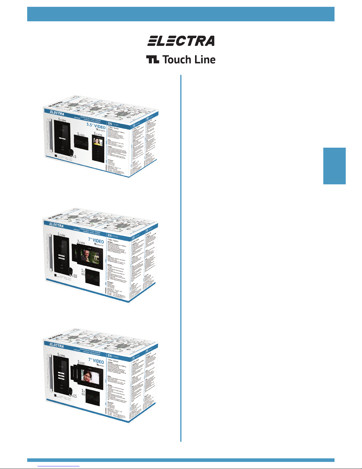
DETAILED PRODUCT CODES
VPM - smart video outdoor panel; Product codes: Video 1Fam.VPM.1S(F)R02.xxy04; 2Fam.VPM.2S(F)R02.xxy04;
3Fam.VPM.3S(F)R02.xxy04; 5Fam.VPM.5S(F)R02.xxy04 (S= Surface mounting, F= Flush mounting, R= RFID CARD/TAG access)
RFID access CARD/TAG (secured at reading and copying). They are stored and can be deleted from the VPM.
ATM - smart+ audio terminal; Product code: ATM.0S402.xxy04
VTM - smart+ 3.5” video terminal; Product code: VTM.3S402.xxy04,
VTM/VTE - smart+/extra 7” video terminal; Product codes: VTM.7S402.xxy04/ VTE.7S902.xxy04
VCB – Video connection box (1 video input/4 video outputs - 4 Fam.); Product code: VCB.4DN02.xxy04
EN
INSTALLATION INSTRUCTIONS – VIDEO DOOR PHONE KIT
Dear Customer, thank you for choosing the ELECTRA products. We will assist you throughout the entire warranty period.
For technical support and assistance you can contact us at ELECTRA Building Communications GmbH WIEN,
+43 1 810 20 99, sales@electra-automation.com.
2
1) Max. 75 ml 4 x 0.5 mm (H03VV-F4G 0.5)
2
2) Max. 150 ml 4 x 0.75 mm (H05VV-F4G 0.75)
3) Max. 250 ml UTP cat5e (AWG24) or UTP cat6e (AWG23)
Page 3

EN
VSB – Video selection box; Product code: VSB.4DN02.xxy04 (4 video inputs/1 video output)
SCU – Central supply unit for 1 Fam; Product code: SCU.VDR02.xxy14 (110-230Vc.a., 50Hz/13.5Vd.c.-2Ad.c.).
Central supply unit for 3 Fam; Product code: SCU.VDR02.xxy34
PSU – Additional supply unit; Product code: PSU.VDR02.xxy04, necessary when, due to various reasons, the supply voltage
(+U, GND) at the hubs of the terminals drops below 12V. See the user manual of the SCU central supply unit.
Vcam – Additional video camera connection, analogic 1Vv-v, PAL
LC1/LC2 – Connection of direct current lock (max.0.6A/12Vd.c.) Door locked: Ulock = 0Vc.c./indefinite time. Door open:
Ulock = 12Vd.c./max. 0,75Ac.c./max. 10 sec.
LA1/LA2 – Connection of alternating current lock (max.5A/12Va.c.) Door locked: Ulock = 0Va.c./indefinite time. Door open:
Ulock = 12Va.c./24Va.c./max. 5,0Aa.c./max. 10 sec. (point 2, pg. 15)
LS1/LS2 – Connection of electromagnetic lock (max.3A/24Vc.c.) Door locked: Ulock = 12Vd.c./24Vd.c./max. 3,0Ad.c./
indefinite time. Door open: Ulock = 0Vd.c./max. 10 sec. (point 3)
SWC1/SWC2 – Connection of EXIT button (mounted inside the building)
AUX1/AUX2 – Connection of additional installations – auto gate, garage door, outdoor lighting etc. (point 4)
+ BAT/- BAT – Connection of rechargeable battery
DBL1/DBL2 – Connection of entrance doorbell (apartment doorbell)
GNG1/GNG2 – Connection of distance call doorbell (GONG)
B.
1. Normal functioning mode, without BAT: the (Network) and +U LEDs are Green. The PROG and BAT LEDs are turned off.
2. Normal functioning mode, with BAT connected: the (Network), BAT and +U LEDs are Green.
3. The system functions only on battery (the system functions correctly until the full discharge of the battery): the BAT LED is
Green, the (Network) and +U LEDs are turned off. Check the fuses on the SCU (FUSE T-1, 6A) and 2x6A from the Network.
4. The system functions with a broken battery. The , +U LEDs are Green, the BAT LED is turned off. Change the battery!!!
5. The outdoor panel does not function (the Red LED from the video camera does not blink, the call keys are not backlighted):
The , BAT and +U LEDs are Green. The outdoor panel LED from the SCU is Red. Check the continuity and the accuracy of the
+U and GND connections from the SCU to the panel.
6. A terminal does not function (the keys are not backlighted when touched, there is no image and sound): the , BAT
and +U LEDs are Green. One of the OUT1, OUT2 or OUT3 LEDs is Red. Check the continuity and accuracy of the +U or GND
connections from the SCU to the terminal.
7. The direct current lock does not function (LC1, LC2), the LED is Red: check the accuracy of the connections to the lock.
8. The display of the terminal is Blue or Black (it functions during audio call): check the continuity of the Vin, Vout and GND
connections from the outdoor panel to the video terminal. If the connections are good, change the terminal.
9. The terminal cannot be called: a) (Terminal 2 or 3 has an incorrect address. The terminal at Family 1 is called!) Reprogram
terminals 2 or 3 with the correct address (the apartment number) according to Step 6.2.
b) If the PROG LED from the SCU is Red, check the continuity and the accuracy of the C/D, +U and GND connections from the
outdoor panel to the video terminal.
TROUBLESHOOTING AND SERVICE FOR THE VIDEO DOOR PHONE SYSTEM
PARALLEL CONNECTION OF TWO OUTDOOR PANELS (See the diagram from point 10)
If the building has multiple entrances, you can install VPM outdoor panels with their own SCU central supply unit, which will
command its own gate. The VPM1 main outdoor panel keeps address 1, set by the manufacturer and only the RFID access
cards/tags will be programmed at the VPM1 (see Step 5.1). The VPM2 additional panel is programmed with address 2 and
with the RFID access cards/tags (see Step 5.2).
PARALLEL CONNECTION OF THE ADDITIONAL TERMINALS (See the diagram from point 9)
Inside the residence you can install TL additional terminals (ATM/VTM 3.5”/ VTM 7”/ VTE 7”) using the same type
of cable, for the same connections (+U, C/D, GND, Vin/Vout). All the terminals in one apartment will have the
address of the main terminal. For Fam.1 the terminals have address 1 set by the producer. For Fam. 2, 3
(Fam. 4, 5 or more), program the terminals with addresses 2, 3 (or 4, 5 etc.). See Step 6.2.
2
Page 4

4
5
+U
C/D
GND
Vin
+U
C/D
6mm
25-30mm
GND
Vout
6mm
25-30mm
+U
C/D
GND
+U
C/D
GND
UTP cat5e (AWG24)
UTP cat6e (AWG23)
25-30mm
6mm
VinVout
6mm
25-30mm
2
1) Max. 75 ml 4 x 0.5 mm (H03VV-F4G 0.5)
2
2) Max. 150 ml 4 x 0.75 mm (H05VV-F4G 0.75)
3) Max. 250 ml UTP cat5e (AWG24)/UTP cat6e (AWG23)
SWC1
SWC2
LA1
LA2
LS1
LS2
N L
+U
C/D
GND
Vin1
LC1
LC2
DOOR LOCKS
VIDEO DOOR PANEL
2x6Aa.c.
N
L
max. 24 Va.c.
50Hz/60Hz
LCK
LCK
VPM
max. 24Va.c./5Aa.c.
110Va.c./230Va.c.
50Hz/60Hz
110Va.c./230Va.c.
50Hz/60Hz
SCU
max. 24Vc.c./3Ac.c.
SWC1
SWC2
LA1
LA2
LS1
LS2
N L
+U
C/D
GND
Vin1
LC1
LC2
DOOR LOCKS
VIDEO DOOR PANEL
max. 24 Vc.c.
Electromagnet
110Va.c./230Va.c.
50Hz/60Hz
max. 3 Ac.c.
+U GND
2x6Aa.c.
N
L
110Va.c./230Va.c.
50Hz/60Hz
AUX1
AUX2
+BAT
-BAT
+U
Vin2
GND
3-5 sec.
max. 24V/1A(a.c./c.c.)
3
1
2
3
LED PROGPROG
SCU
SCU
SCU
SCU
EN
Page 5

Vcam
+U
GND
Vin2
SWC 1
SWC 2
SWC
LC 1
LC 2
LCK
AUX 1
AUX 2
LA 1
LA 2
LS 1
LS 2
AUX
,
Fam. 1
(Adr. 1)
VPM
(Adr.1)
GNG 2
GNG 1
DBL 1
DBL 2
Doorbell
+U
C/D
GND
Vout
+U
C/D
GND
Vout
+U
C/D
GND
Vin
+U
C/D
GND
Vin
OUT
IN
Fam 1
GONG
SCU
OUT1
+U
PROG
BAT 110/230V
+BAT
-BAT
12V/7Ah
BAT
+
-
IN
110Va.c., 50Hz, 60Hz
230Va.c., 50Hz, 60Hz
L N
2x6Aa.c.
6
4
EN
Page 6

Vout
OUT
IN
SWC 1
SWC 2
SWC
LC 1
LC 2
LCK
AUX 1
AUX 2
LA 1
LA 2
LS 1
LS 2
AUX
,
Vin
SCU
+BAT
-BAT
12V/7Ah
BAT
+
-
Fam 1
Vout
+U
C/D
GND
Vout
OUT2OUT1
Fam. 1 (Adr. 1)
GNG 2
GNG 1
DBL 1
DBL 2
Doorbell
+U
C/D
GND
Vin
GONG
Doorbell
GONG
5
+U
C/D
GND
Vcam
+U
GND
Vin2
110Va.c., 50Hz, 60Hz
230Va.c., 50Hz, 60Hz
L N
2x6Aa.c.
+U
C/D
GND
OUT3
+U
PROG
BAT 110/230V
Fam 2
+U
C/D
GND
IN
Fam. 2 (Adr. 2)
GNG 2
GNG 1
DBL 1
DBL 2
+U
C/D
GND
Vin
7
VPM
(Adr.1)
EN
Page 7

+U
C/D
GND
Vout
OUT
IN
Fam. 3 (Adr. 3)
GNG 2
GNG 1
DBL 1
DBL 2
Doorbell
+U
C/D
GND
Vin
GONG
Vcam
+U
GND
Vin2
SWC 1
SWC 2
SWC
LC 1
LC 2
LCK
AUX 1
AUX 2
LA 1
LA 2
LS 1
LS 2
AUX
,
110Va.c., 50Hz, 60Hz
230Va.c., 50Hz, 60Hz
L N
2x6Aa.c.
+U
C/D
GND
Vout
+U
C/D
GND
Vin
SCU
OUT3
+U
PROG
BAT 110/230V
+BAT
-BAT
12V/7Ah
BAT
+
-
Fam 2
Fam 1
Fam 3
+U
C/D
GND
Vout
+U
C/D
GND
Vout
OUT2OUT1
IN
RO
Fam. 1 (Adr. 1)
GNG 2
GNG 1
DBL 1
DBL 2
Doorbell
+U
C/D
GND
Vin
GONG
Fam. 2 (Adr. 2)
GNG 2
GNG 1
DBL 1
DBL 2
Doorbell
+U
C/D
GND
Vin
GONG
8
6
VPM
(Adr.1)
EN
Page 8

9
10
Designed and Manufactured by ELECTRA Made in EU
11.2017 INS.VK3.ELY04
+U
C/D
GND
Vin
+U
C/D
GND
Vout
GONG
DOORBELL
DBL1
DBL2
GNG1
GNG2
VTM.7S402.xxy04/VTE.7S902.xxy04
VIDEO 7"
+U
C/D
GND
Vin
+U
C/D
GND
Vout
+U
C/D
GND
Vin
VIDEO 3.5"
VTM.3S402.xxy04
AUDIO
ATM.0S402.xxy04
7
VPM1
(Adr. 1)
1
VPM2
(Adr. 2)
2
VTM.7S402.xxy04/
VTE.7S902.xxy04/
VTM.3S402.xxy04/
ATM.0S402.xxy04/
+U
C/D
GND
Vout
+U
C/D
GND
Vout
+U
C/D
GND
Vin
+U
C/D
GND
Vout
+U
C/D
GND
Vin
OUT 1
SCU1
+U
C/D
GND
Vout
+U
C/D
GND
Vout
+U
C/D
GND
Vin
OUT 1
SCU2
VSB
+U
C/D
GND
Vin
+U
C/D
GND
Vin
OUT
IN 1
IN 2
VIDEO PANEL
VIDEO PANEL
Fam 2
Fam 1
Fam 3
Fam 4
Fam 5
Fam 2
Fam 1
Fam 3
Fam 4
Fam 5
VCB
OUT 1
IN
OUT 2 OUT 3
OUT 4
+U
C/D
GND
Vout
+U
C/D
GND
Vout
+U
C/D
GND
Vout
OUT
Fam.1
Fam.2
Fam.3
+U
C/D
GND
Vout
Fam.4
+U
C/D
GND
Vout
Fam.5
IN 4IN 3
SWC 1
SWC 2
SWC
LC 1
LC 2
LCK
AUX 1
AUX 2
LA 1
LA 2
LS 1
LS 2
AUX
,
SWC 1
SWC 2
SWC
LC 1
LC 2
LCK
AUX 1
AUX 2
LA 1
LA 2
LS 1
LS 2
AUX
,
Vcam
+U
GND
Vin2
110Va.c., 50Hz, 60Hz
230Va.c., 50Hz, 60Hz
L N
2x6Aa.c.
Vcam
+U
GND
Vin2
110Va.c., 50Hz, 60Hz
230Va.c., 50Hz, 60Hz
L N
2x6Aa.c.
ELECTRA s.r.l
Bd. Chimiei nr.8, Iași - 700291 - RO
+40 232 214.370 +40 232 232.830
sales@electra.ro
www.electra.ro
ELECTRA
Bischoffgasse 5/3-4, 1120 Wien - AT
+43 1 810 20 99
Building Communications GmbH
Certificate no. E307311
ISO 9001:2008
ISO 14001:2009
Certificates no. 73 100 4856, 73 104 4856
by TÜV HESSEN
The products are manufactured under
Quality and Environment Management System
The products are
CE certified.
R
The products contain UL-compliant
printed circuit boards.
ELECTRA is a trademark of ELECTRA Group - No. 008958332 EUIPO - Alicante, Spain
ELECTRA products are registered as Industrial Models at EUIPO - Alicante, Spain
License by
R
709
ICPE
sales@electra-automation.at
www.electra-automation.at
EN
 Loading...