

Page 1

TRIO DELTA 5.2
CONTENTS
Indoor Units Outdoor Units
DELTA 22
DELTA 25
DELTA 35
TRIO Delta 5.2 DCI
SM TRIO52 1-E.1 GB
REFRIGERANT
R410A HEAT PUMP
OCTOBER – 2008
Page 2
LIST OF EFFECTIVE PAGES
CONTENTS
LIST OF EFFECTIVE PAGES
Note: Changes in the pages are indicated by a “Revision#” in the footer of each effected page
(when none indicates no changes in the relevant page). All pages in the following list represent
effected/ non effected pages divided by chapters.
Dates of issue for original and changed pages are:
Original ....... 0 ........ May 2006
Total number of pages in this publication is 56 consisting of the following:
Page
No.
Title ....................... 1
A ........................... 1
i ............................. 1
1-1 ........................ 1
2-1 - 2-4 ................ 1
3-1 ........................ 1
4-1 - 4-2 ................ 1
5-1 - 5-6 ................ 1
6-1 - 6-6 ................ 1
7-1 ........................ 1
8-1 ........................ 1
9-1 ........................ 1
10-1 ...................... 1
11-1-11-15 ............. 1
12-1-12-6 .............. 1
13-1-13-2 .............. 1
Appendix -A ...........1
Revision
No. #
Page
No.
Revision
No. #
Page
No.
Revision
No. #
• Zero in this column indicates an original page.
*Due to constant improvements please note that the data on this service manual can be modified
with out notice.
**Photos are not contractual
A
SM TRIO52 1- E.1 GB
Page 3

TABLE OF CONTENTS
Table of Contents
1. INTRODUCTION ...................................................................................................1-1
2. PRODUCT DATA SHEET ......................................................................................2-1
3. RATING CONDITIONS ..........................................................................................3-1
4. OUTLINE DIMENSIONS .......................................................................................4-1
5. PERFORMANCE DATA .......................................................................................5-1
6. PRESSURE CURVES ...........................................................................................6-1
7. ELECTRICAL DATA ..............................................................................................7-1
8. WIRING DIAGRAMS .............................................................................................8-1
9. REFRIGERATION DIAGRAMS .............................................................................9-1
10. TUBING CONNECTIONS ......................................................................................10-1
11. CONTROL SYSTEM .............................................................................................11-1
12. TROUBLESHOOTING ..........................................................................................12-1
13. EXPLODED VIEWS AND SPARE PARTS LISTS .................................................13-1
14. APPENDIX A .........................................................................................................14-1
SM TRIO52 1- E.1 GB
i
Page 4
1. INTRODUCTION
CONTENTS
1.1 General
The new Trio 5.2 Delta DCI Outdoor Unit is a high efficiency multi split inverter unit,
supporting Indoor Units capacity range of - 2.2, 2.5 and 3.5 Kw.
1.2 Main Features
• DC Inverter
• R410A
• High COP (A class energy rating)
• Pre-Charged
• Base heater connection.
• Heating operation at outdoor temperature down to -150C.
• 10 LED’s, shows both indoor and outdoor diagnostics.
• Variable Speed DC Inverter outdoor fan.
• M2L diagnostics softwear cable Port ( for PC).
• Low noise level
INTRODUCTION
1.3 Tubing Connections
Flare type interconnecting tubing to be produced on site.
For further details please refer to APPENDIX A on this manual, and to the relevant indoor
service Manual,
1.4 Inbox Documentation
Each indoor unit is supplied with its own installation and operation manuals.
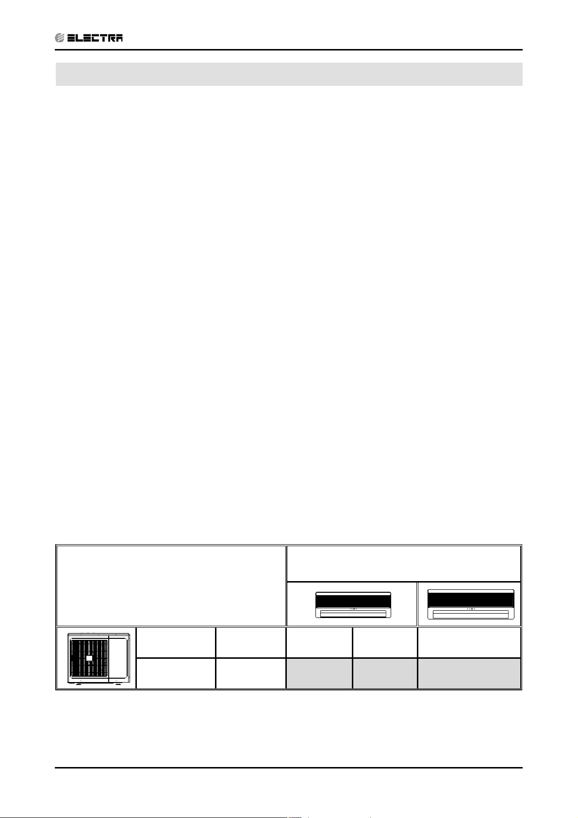
1.5 Matching Table
1.5.1 R410A
OUTDOOR UNITS
MODEL REFRIGERANT DELTA 22 DCI DELTA 25 DCI DELTA 35 DCI
INDOOR UNITS
SM TRIO52 1- E.1 GB
Trio 5.2 Delta DCI R410A
√√ √
1-1
Page 5
PRODUCT DATA SHEET
CONTENTS
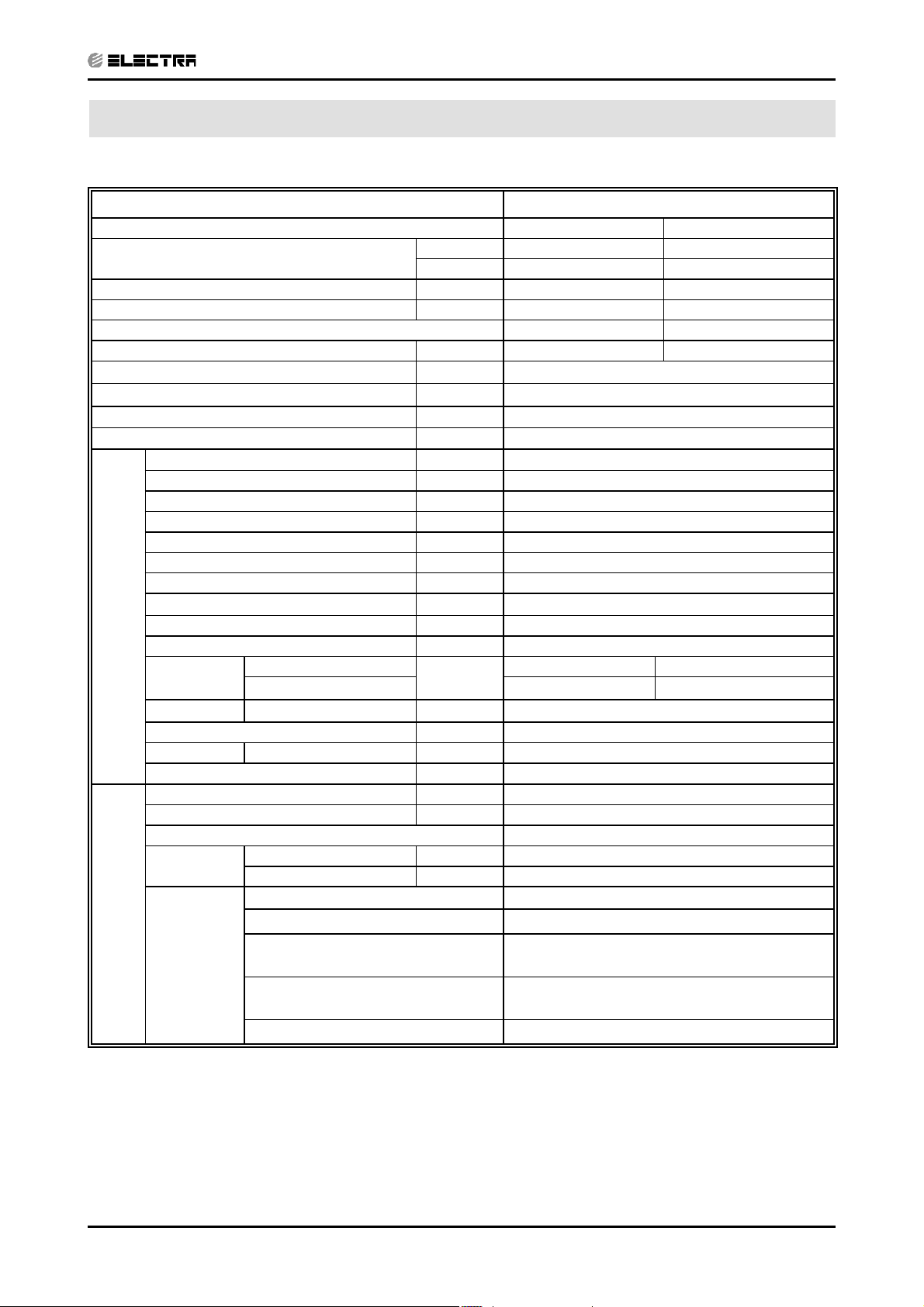
2. PRODUCT DATA SHEET
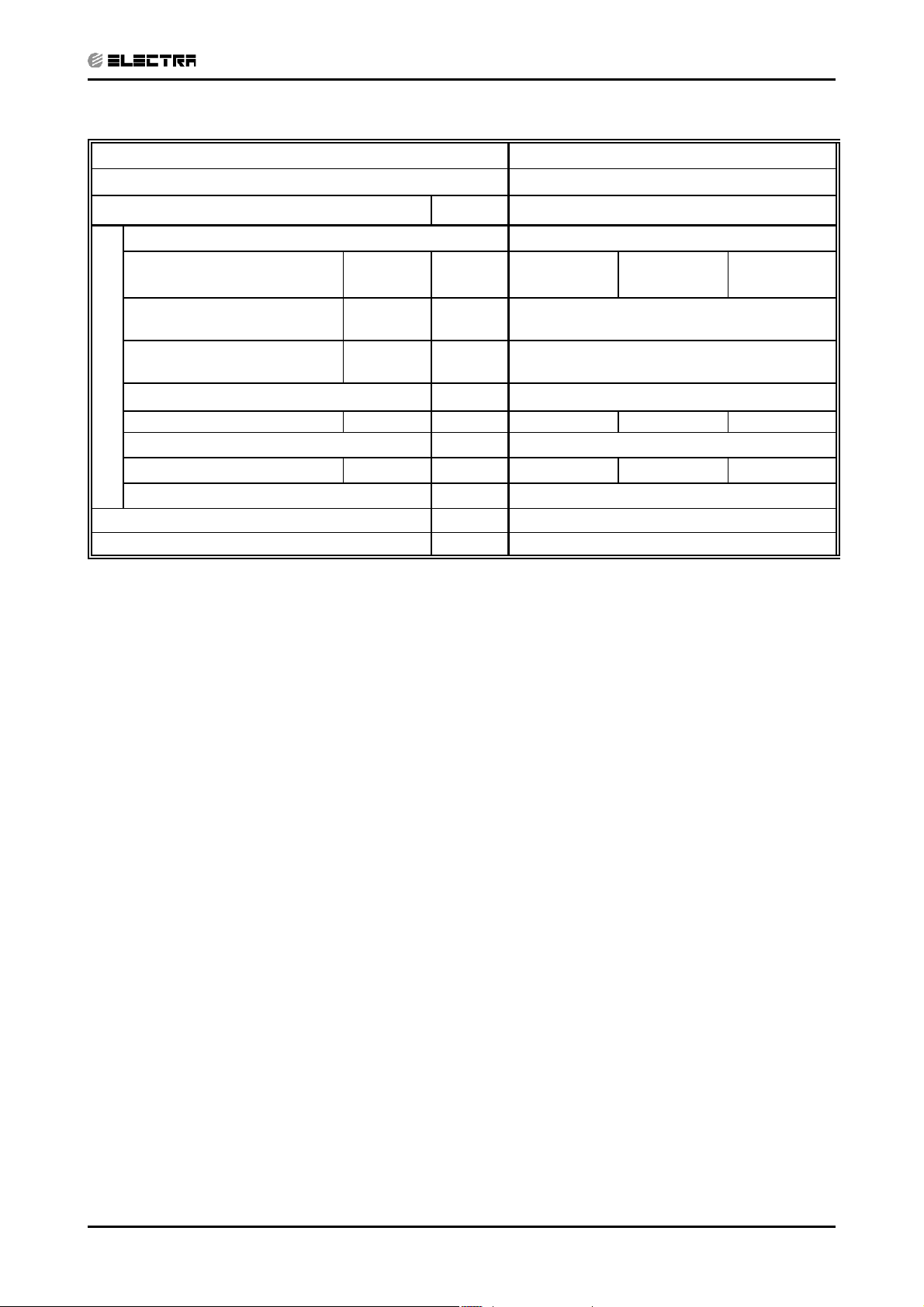
2.1 Outdoor Unit TRIO 5.2 Delta Specifications.
Model TRIO Delta 5.2kw DCI R410A
Operation Mode Cooling Heating
Capacity
Total Input W 1550(450~2150) 1800(450~1900)
E.E.R (Cooling) / C.O.P (Heating) W/W 3.35 3.67
Energy efficienty class A A
Running Current
Starting Current A 10.5
Inrush Current A 35.0
Power Supply V/Ph/Hz Single Phase / 50Hz / 230V
Dehumidification L/h 1.7
Refrigerant control Electronic expansion valve
Compressor type Scroll DC Inverter
Model Panasonic 5CS130XCC03
Starter type --Protection device Outdoor SW control
Heat exchanger Hydrophilic flat fin, Grooved tube coil
Fan x No. Propeller x 1
Airflow m
Motor output W 70
Defrost method Reverse cycle
OUTDOOR UNIT
Noise level
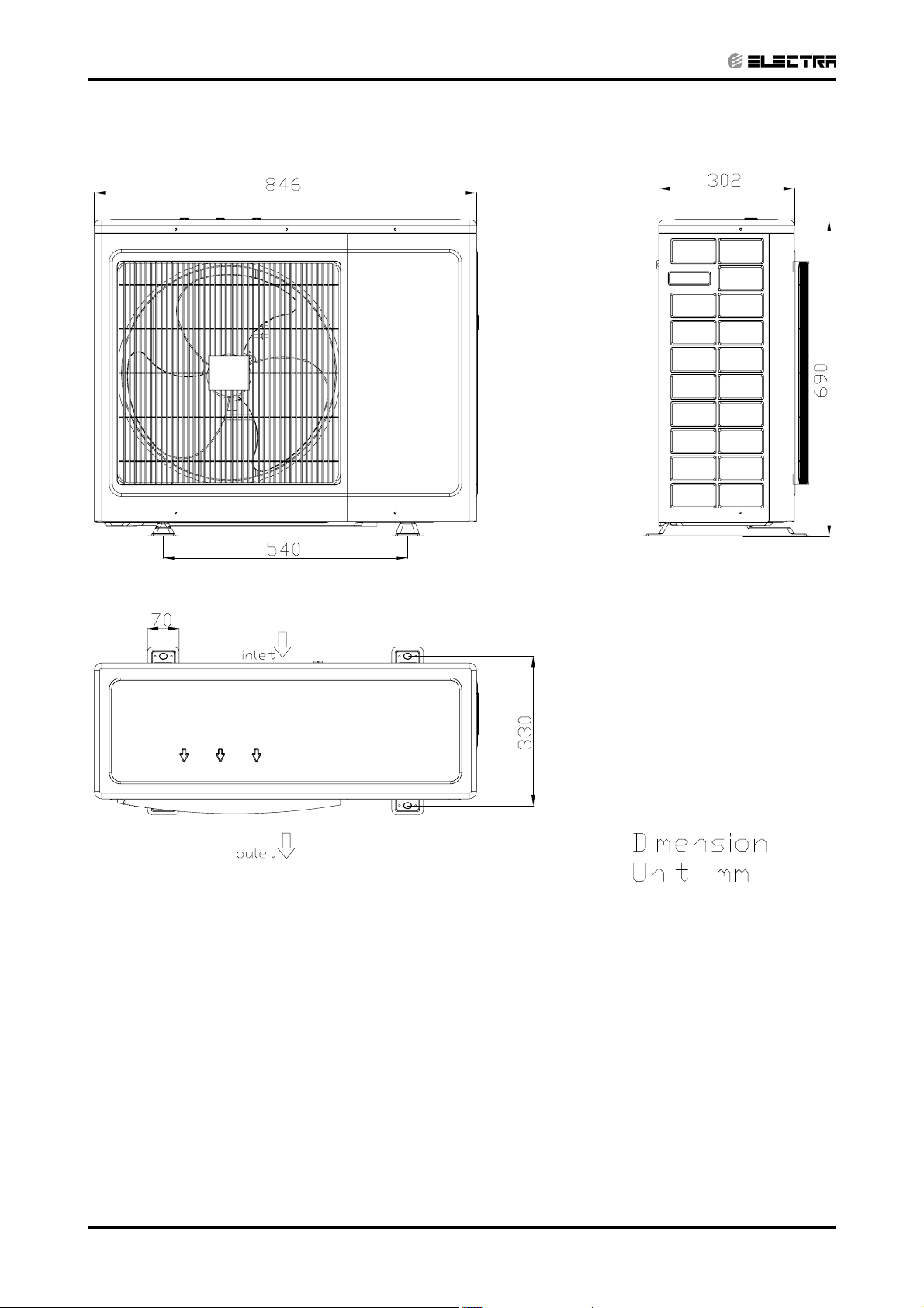
Dimensions W*H*D mm 846*690*302
Weight Kg 48
Package W*H*D mm 990X770X430
Unit stacking # 3
Refrigerant Charge Kg R410A
Charge (7.5m connection tube) g 1850
Fresh Air NO
Tube size
O.D.
Connection
TUBING
method
between the
indoor and
outdoor units
(3)
(4)
Indoor & outdoor Flared
Height difference between indoor units Max.5m
Height difference between indoor &
outdoor
Tubing length
Additional charge No need
Pressure
Power 63 67
Liquid mm 6.35
Suction mm 9.5
Btu/hr 17747(2389~22184) 22525(3413~29914)
W 5200 (1000~6500) 6600(1000~7300
A6.7 7.8
3
/hr 2860
dB(A)
Standard 7.5m Max. 25m for one unit and 35m for
50 56
Max.5m
total
SM TRIO52 1- E.1 GB
2-1
Page 6
PRODUCT DATA SHEET
CONTENTS
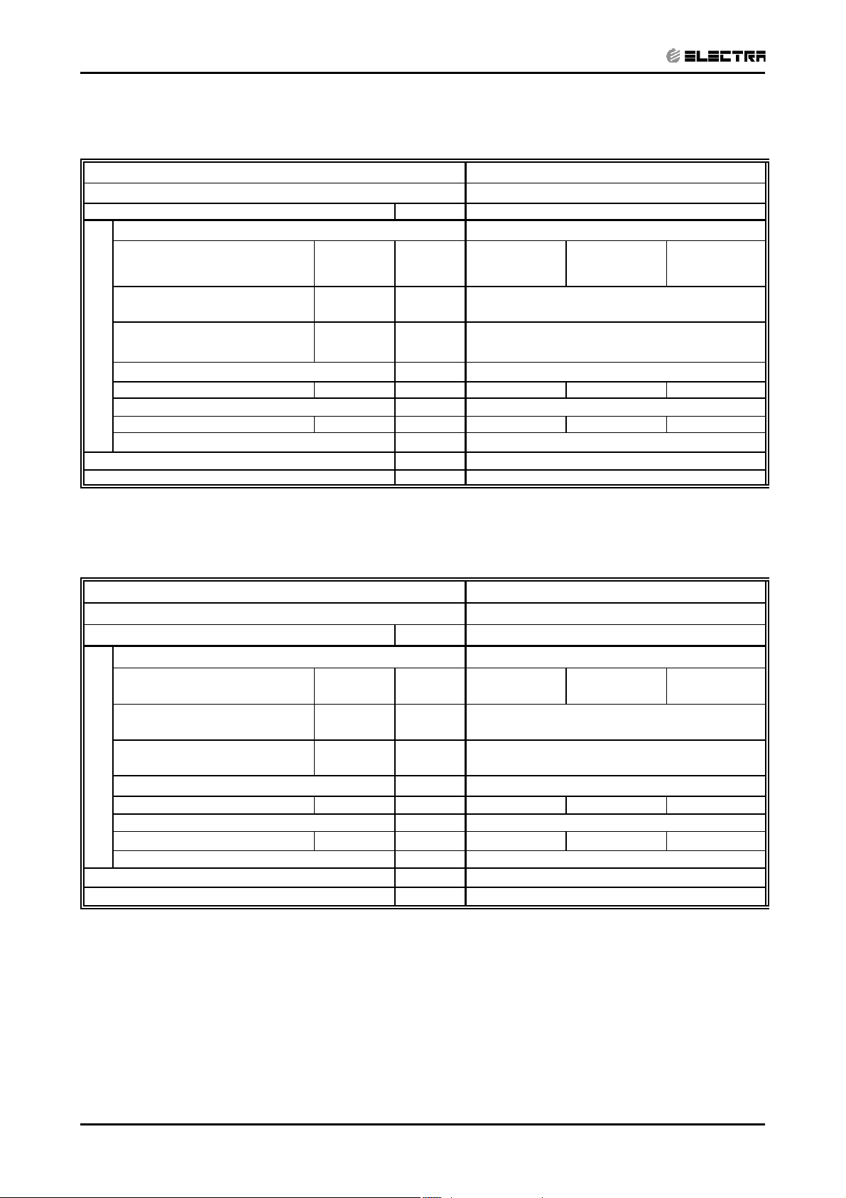
2.2 Indoor Units Data
2.2.1 DELTA 22 DCI Specifications
Model Indoor Unit / Type DELTA 22 DCI / Wall Mounted
Installation Method FLARE
Power Supply V/Ph/Hz 220-240 / 1/ 50
Fan Type & Quantity Crossflow *1
(2)
Airflow
Cooling / Heating
Sound Power Level
Cooling / Heating
Sound Pressure Level
Cooling / Heating
INDOOR
(3)
(4)
H/M/L m
L - H dB (A) 49/46/43
L - H dB (A) 36/33/30
Condensate Drain Tube I.D. mm 16
Dimensions W/H/D mm 680 250 185
Weight kg 7
Package Dimensions W/H/D mm 740 320 265
Stacking Height Units 9 LEVELS
Heating Elements kW N/A
Moisture Removal L/hr 1
3
/hr 400 350 300
2.2.2 DELTA 25 DCI Specifications
Model Indoor Unit / Type DELTA 25 DCI / Wall Mounted
Installation Method FLARE
Power Supply V/Ph/Hz 220-240 / 1/ 50
Fan Type & Quantity Crossflow *1
(2)
Airflow
Cooling / Heating
Sound Power Level
(3)
Cooling / Heating
Sound Pressure Level
Cooling / Heating
INDOOR
Condensate Drain Tube I.D. mm 16
(4)
H/M/L m
L - H dB (A) 52/48/45
L - H dB (A) 39/35/32
Dimensions W/H/D mm 680 250 185
Weight kg 7
Package Dimensions W/H/D mm 740 320 260
Stacking Height Units 9 LEVELS
Heating Elements kW N/A
Moisture Removal L/hr 1.0
(1) Rating conditions in accordance with ISO 5151 and ISO 13253 (for ducted units) and EN14511.
(2) Airflow in ducted units; at nominal external static pressure.
(3) Sound power in ducted units is measured at air discharge.
(4) Sound pressure level measured at 1 meter distance from unit.
3
/hr 420 350 270
2-2
SM TRIO52 1- E.1 GB
Page 7
PRODUCT DATA SHEET
CONTENTS
2.2.3 DELTA 35 DCI Specifications
Model Indoor Unit / Type DELTA 35 DCI / Wall Mounted
Installation Method FLARE
Power Supply V/Ph/Hz 220-240 / 1/ 50
Fan Type & Quantity Crossflow *1
(2)
Airflow
Cooling / Heating
Sound Power Level
(3)
Cooling / Heating
(4)
Sound Pressure Level
Cooling / Heating
INDOOR
Condensate Drain Tube I.D. mm 16
H/M/L m
L - H dB (A) 56/46/42
L - H dB (A) 39/33/29
Dimensions W/H/D mm 840 250 185
Weight kg 8.0
Package Dimensions W/H/D mm 930 320 265
Stacking Height Units 9 LEVELS
Heating Elements kW N/A
Moisture Removal L/hr 1.5
3
/hr 550 450 350
(1) Rating conditions in accordance with ISO 5151 and ISO 13253 (for ducted units) and EN14511.
(2) Airflow in ducted units; at nominal external static pressure.
(3) Sound power in ducted units is measured at air discharge.
(4) Sound pressure level measured at 1 meter distance from unit.
SM TRIO52 1- E.1 GB
2-3
Page 8
PRODUCT DATA SHEET
CONTENTS
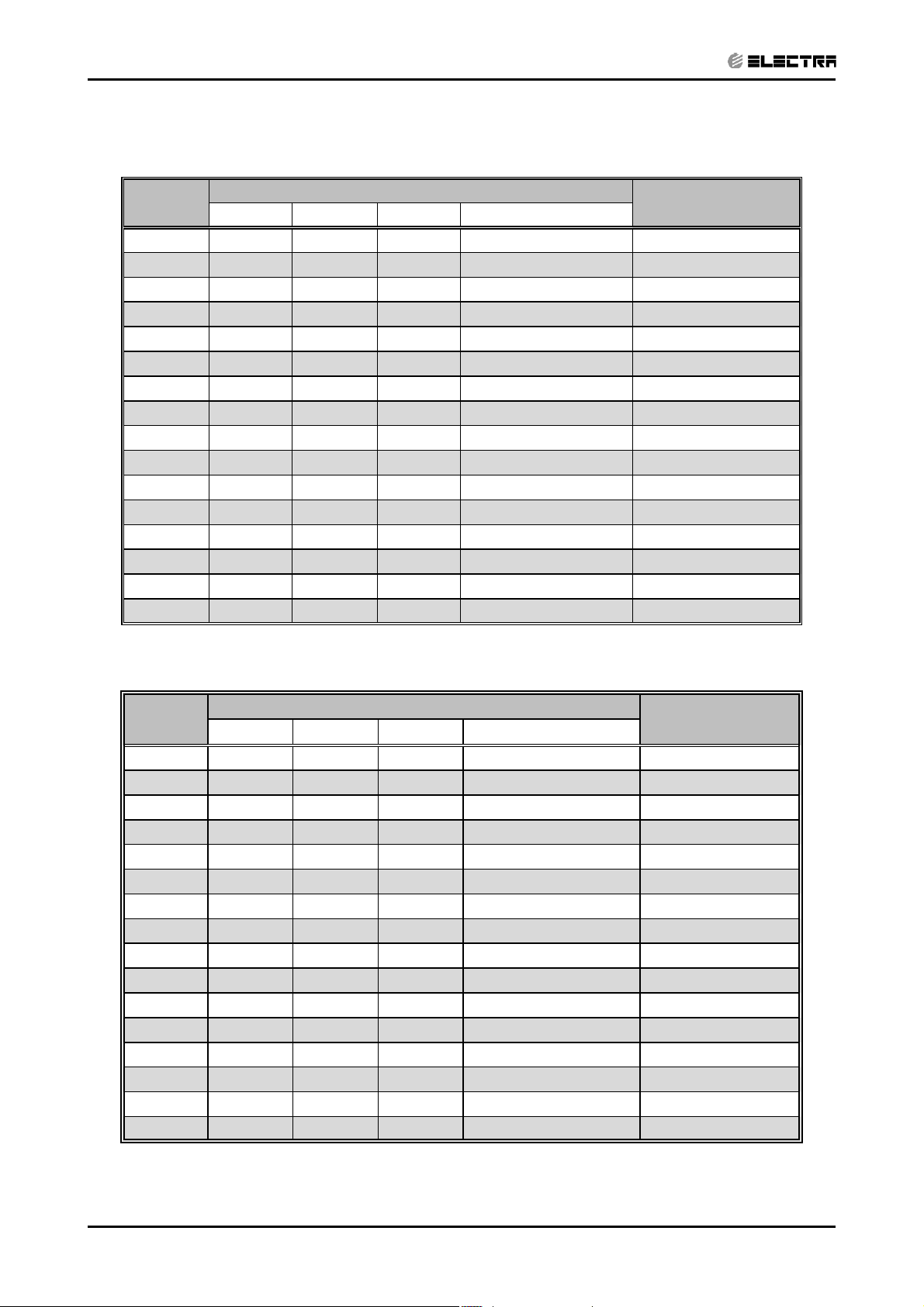
2.3 Indoor Units Combinations
2.3.1 Cooling
Model
22 2200 - - 2200(1050-2600) 645(450-750)
25 2500 - - 2500(1100-3500) 740(510-1040)
35 3500 - - 3500(1200-4200) 1020(510-1250)
22+22 2000 2000 - 4000(1400-5100) 1170(520-1500)
22+25 2000 2150 - 4150(1450-5200) 1220(530-1530)
22+35 2000 3000 - 5000(1720-6200) 1450(610-1910)
25+25 2150 2150 - 4300(1710-6200) 1250(610-1910)
25+35 2150 3000 - 5150(1710-6280) 1510(600-1930)
35+35 3000 3000 - 6000(1800-6400) 1720(635-2110)
22+22+22 1700 1700 1700 5100(1860-6420) 1500(636-2000)
22+22+25 1700 1700 1730 5130(1870-6420) 1510(636-2000)
22+22+35 1700 1700 2600 6000(1870-6450) 1720(635-2110)
22+25+25 1700 1730 1730 5160(1870-6450) 1500(635-2110)
22+25+35 1700 1730 2600 6030(1880-6450) 1730(640-2115)
25+25+25 1730 1730 1740 5200(1860-6440) 1550(640-2020)
25+25+35 1730 1730 2600 6060(1880-6500) 1740(640-2130)
ABCTotal Capacity
Cooling Capacity [W]
Total Power[W]
2.3.2 Heating
Model
ABC Total Capacity
22 2600 - - 2600(1200-3000) 708(450-800)
25 3000 - - 3000(1200-3500) 795(450-920)
35 4200 - - 4200(1200-4500) 1080(510-1160)
22+22 2500 2500 - 5000(1600-6000) 1280(460-1560)
22+25 2500 2650 - 5150(1600-6150) 1300(460-1560)
22+35 2500 3350 - 5850(2000-7100) 1420(510-1920)
25+25 2650 2650 - 5300(1800-6500) 1350(480-1600)
25+35 2650 3350 - 6000(2000-7100) 1450(510-1920)
35+35 3350 3350 - 6700(2100-7150) 1700(515-1930)
22+22+22 2100 2100 2100 6300(2100-7220) 1665(525-1980)
22+22+25 2100 2100 2200 6400(2100-7250) 1670(525-1980)
22+22+35 2100 2100 3020 7220(2120-7260) 1870(530-2000)
22+25+25 2100 2200 2200 6500(2120-7260) 1680(635-2000)
22+25+35 2100 2200 3020 7320(2130-7560) 1660(640-2105)
25+25+25 2200 2200 2200 6600(2120-7260) 1800(640-2000)
25+25+35 2200 2200 3020 7420(2200-7600) 1910(640-2110)
Heating Capacity [W]
Total Power[W]
2-4
SM TRIO52 1- E.1 GB
Page 9
3. RATING CONDITIONS
CONTENTS
Standard conditions in accordance with ISO 5151, ISO 13253 (for ducted units)
and EN 14511.
Cooling:
Indoor: 27oC DB 19oC WB
Outdoor: 35 oC DB
Heating:
Indoor: 20oC DB
Outdoor: 7oC DB 6oC WB
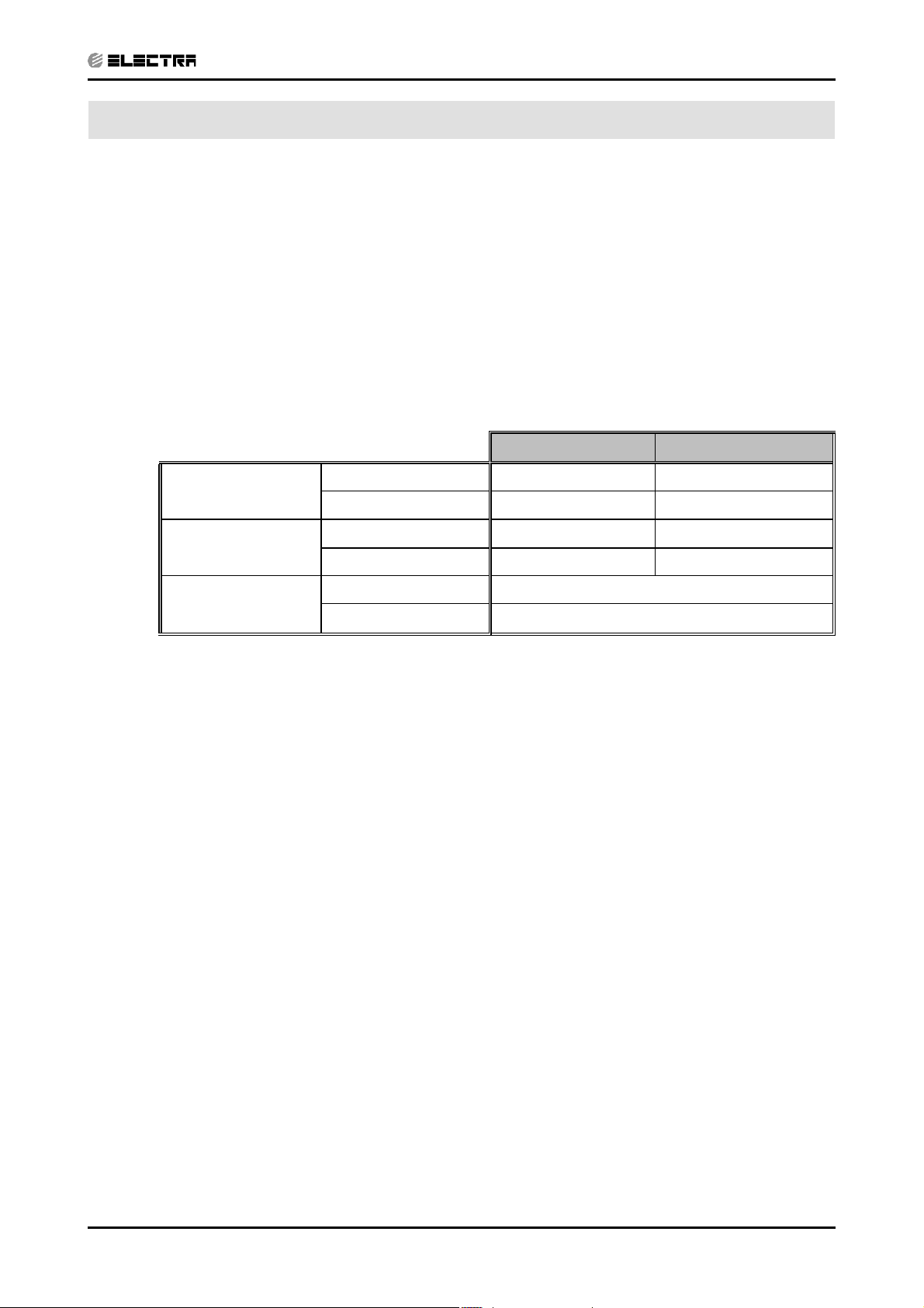
3.1 Operating Limits
Upper limit 32
Cooling
Lower limit 21
Upper limit 27
Heating
Lower limit 10oC DB -15oC DB -16oC WB
RATING CONDITIONS
Indoor Outdoor
o
C DB 23oC WB 46oC DB
o
C DB 15oC WB 10oC DB
o
C DB 24oC DB 18oC WB
Voltage
1PH 198 – 264 V
3PH N/A
SM TRIO52 1- E.1 GB
3-1
Page 10
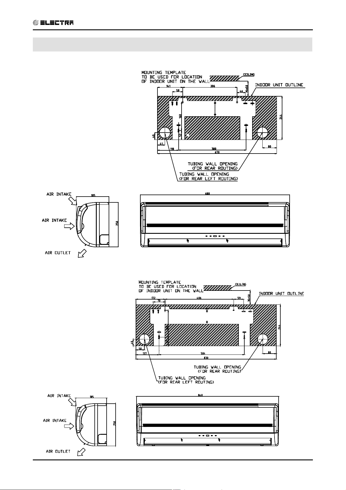
4. OUTLINE DIMENSIONS
CONTENTS
4.1 Indoor Unit: DELTA 22 / 25 DCI
OUTLINE DIMENSIONS
4.2
Indoor Unit: DELTA 35 DCI
SM TRIO52 1- E.1 GB
4-1
Page 11
OUTLINE DIMENSIONS
CONTENTS
4.3 Outdoor Unit: Trio Delta 5.2 DCI
4-2
SM TRIO52 1- E.1 GB
Page 12

5. PERFORMANCE DATA
CONTENTS
5.1 TRIO DELTA 25+25+25
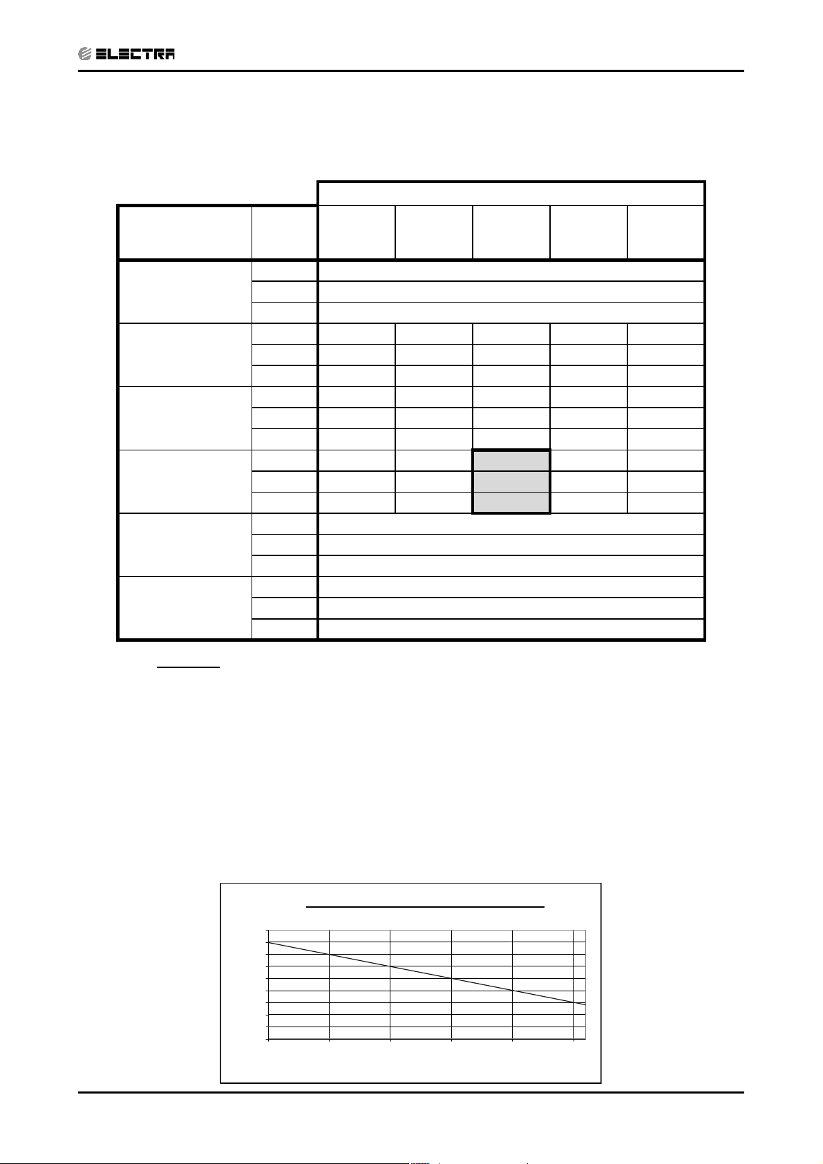
5.1.1 Cooling Capacity (kW) - Run Mode
230[V] : Indoor Fan at High Speed.
ID COIL ENTERING AIR DB/WB TEMPERATURE [C0]
PERFORMANCE DATA
OD COIL ENTERING AIR
DB TEMPERATURE [C0]
-10 - 20
(protection range)
25
30
35
40(Protection Range)
46(Protection Range)
DATA 22/15 24/17 27/19 29/21 32/23
TC 80 - 110 % of nominal
SC 80 - 105 % of nominal
PI 25 - 50 % of nominal
TC 5.58 5.90 6.23 6.56 6.88
SC 4.84 4.95 5.07 5.19 5.30
PI 1.22 1.24 1.27 1.29 1.32
TC 5.06 5.39 5.71 6.04 6.37
SC 4.59 4.71 4.82 4.94 5.05
PI 1.36 1.38 1.41 1.43 1.46
TC 4.55 4.87 5.20 5.53 5.85
SC 4.35 4.46 4.58 4.69 4.81
PI 1.50 1.52 1.55 1.58 1.60
TC 80%-92% of nominal
SC 80%-92% of nominal
PI 80%-92% of nominal
TC 70%-85% of nominal
SC 70%-85% of nominal
PI 90%-100% of nominal
LEGEND
TC – Total Cooling Capacity, kW
PI – Power Input, kW
o
WB – Wet Bulb Temp., (
C)
DB – Dry Bulb Temp., (oC)
ID – Indoor
OD – Outdoor
SC – Sensible Capacity, kW
5.1.2 Capacity Correction Factors
Cooling Capacity Ratio Vs. Outdoor Temperature
1.40
1.30
1.20
1.10
1.00
0.90
0.80
Capacity Ratio
0.70
0.60
0.50
20 25 30 35 40 45
Outdoor Temperature [deg C]
SM TRIO52 1- E.1 GB
5-1
Page 13

PERFORMANCE DATA
CONTENTS
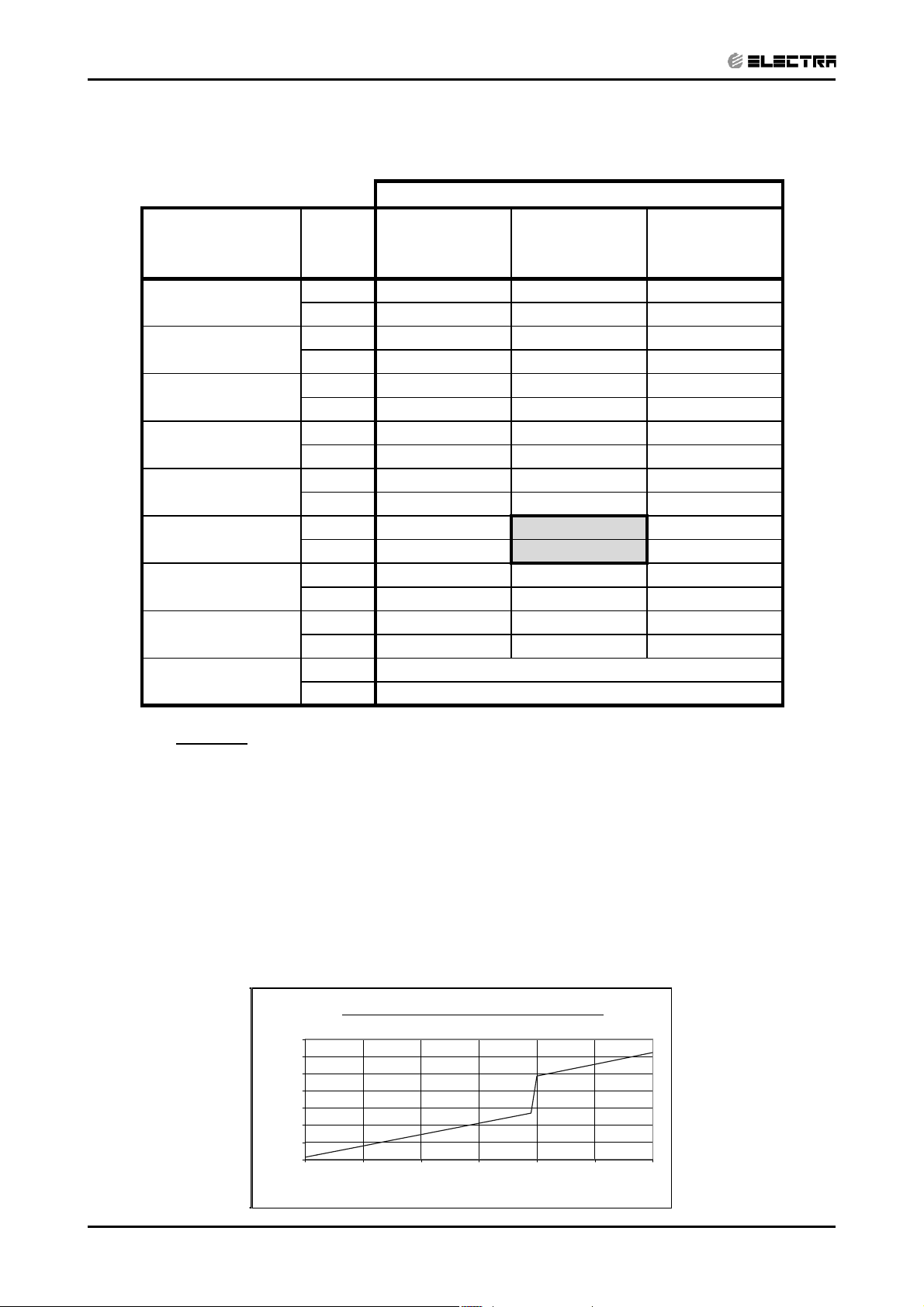
5.1.3 Heating Capacity (kW) - Run Mode
230[V] : Indoor Fan at High Speed.
ID COIL ENTERING AIR DB TEMPERATURE [C0]
OD COIL ENTERING
AIR DB/WB
TEMPERATURE [C0]
DATA 15 20 25
-15/-16
-10/-12
-7/-8
-1/-2
2/1
7/6
10/9
15/12
TC 3.52 3.30 3.08
PI 1.15 1.32 1.48
TC 4.21 3.99 3.78
PI 1.33 1.49 1.66
TC 4.73 4.52 4.30
PI 1.46 1.62 1.79
TC 5.00 4.78 4.56
PI 1.52 1.69 1.86
TC 5.17 4.95 4.73
PI 1.57 1.73 1.90
TC 6.82 6.60 6.38
PI 1.63 1.80 1.97
TC 7.09 6.87 6.65
PI 1.71 1.88 2.04
TC 7.36 7.14 6.92
PI 1.79 1.95 2.12
15-24 TC 85 - 105 % of nominal
(Protection Range) PI 80 - 120 % of nominal
LEGEND
TC – Total Heating Capacity, kW
PI – Power Input, kW
WB – Wet Bulb Temp., (oC)
DB – Dry Bulb Temp., (oC)
ID – Indoor
OU – Outdoor
5.1.4 Capacity Correction Factors
Heating Capacity Ratio Vs. Outdoor Temperature
1.20
1.10
1.00
0.90
0.80
0.70
Capacity Ratio
0.60
0.50
-15 -10 -5 0 5 10 15
Outdoor WB Temperature [deg C]
5-2
SM TRIO52 1- E.1 GB
Page 14
5.2 Delta Trio 25+25+35
CONTENTS
5.2.1 Cooling Capacity (kW) - Run Mode
230[V] : Indoor Fan at High Speed.
ID COIL ENTERING AIR DB/WB TEMPERATURE [C0]
OD COIL
ENTERING AIR DB
TEMPERATURE [C0]
-10 - 20
(protection range)
25
30
35
40(Protection Range)
46(Protection Range)
DATA 22/15 24/17 27/19 29/21 32/23
TC 80 - 110 % of nominal
SC 80 - 105 % of nominal
PI 25 - 50 % of nominal
TC 6.50 6.88 7.26 7.64 8.02
SC 5.64 5.77 5.91 6.04 6.18
PI 1.37 1.40 1.42 1.45 1.48
TC 5.90 6.28 6.66 7.04 7.42
SC 5.35 5.49 5.62 5.76 5.89
PI 1.53 1.55 1.58 1.61 1.64
TC 5.30 5.68 6.06 6.44 6.82
SC 5.06 5.20 5.33 5.47 5.60
PI 1.68 1.71 1.74 1.77 1.80
TC 80%-92% of nominal
SC 80%-92% of nominal
PI 80%-92% of nominal
TC 70%-85% of nominal
SC 70%-85% of nominal
PI 90%-100% of nominal
PERFORMANCE DATA
LEGEND
TC – Total Cooling Capacity, kW
PI – Power Input, kW
o
WB – Wet Bulb Temp., (
C)
DB – Dry Bulb Temp., (oC)
ID – Indoor
OD – Outdoor
SC – Sensible Capacity, kW
5.2.2 Capacity Correction Factors
Cooling Capacity Ratio Vs. Outdoor Temperature
1.40
1.30
1.20
1.10
1.00
0.90
0.80
Capacity Ratio
0.70
0.60
0.50
20 25 30 35 40 45
Outdoor Temperature [deg C]
SM TRIO52 1- E.1 GB
5-3
Page 15
PERFORMANCE DATA
CONTENTS
5.2.3 Heating Capacity (kW) - Run Mode
230[V] : Indoor Fan at High Speed.
ID COIL ENTERING AIR DB TEMPERATURE [C0]
OD COIL ENTERING
AIR DB/WB
TEMPERATURE [C
DATA 15 20 25
0
]
-15/-16
-10/-12
-7/-8
-1/-2
2/1
7/6
10/9
15/12
TC 3.95 3.71 3.46
PI 1.22 1.40 1.57
TC 4.74 4.49 4.25
PI 1.41 1.58 1.76
TC 5.32 5.08 4.83
PI 1.55 1.72 1.90
TC 5.62 5.37 5.13
PI 1.62 1.79 1.97
TC 5.81 5.57 5.32
PI 1.66 1.84 2.02
TC 7.66 7.42 7.18
PI 1.73 1.91 2.09
TC 7.97 7.73 7.48
PI 1.82 1.99 2.17
TC 8.27 8.03 7.79
PI 1.90 2.07 2.25
15-24 TC 85 - 105 % of nominal
(Protection Range) PI 80 - 120 % of nominal
LEGEND
TC – Total Heating Capacity, kW
PI – Power Input, kW
WB – Wet Bulb Temp., (oC)
DB – Dry Bulb Temp., (oC)
ID – Indoor
OU – Outdoor
5.2.4 Capacity Correction Factors
Heating Capacity Ratio Vs. Outdoor Temperature
1.20
1.10
1.00
0.90
0.80
0.70
Capacity Ratio
0.60
0.50
-15 -10 -5 0 5 10 15
Outdoor WB Temperature [deg C]
5-4
SM TRIO52 1- E.1 GB
Page 16

5.3 Delta Trio 35+35
CONTENTS
5.3.1 Cooling Capacity (kW) - Run Mode
230[V] : Indoor Fan at High Speed.
ID COIL ENTERING AIR DB/WB TEMPERATURE [C0]
OD COIL
ENTERING AIR DB
TEMPERATURE [C0]
-10 - 20
(protection range)
25
30
35
40(Protection Range)
46(Protection Range)
DATA 22/15 24/17 27/19 29/21 32/23
TC 80 - 110 % of nominal
SC 80 - 105 % of nominal
PI 25 - 50 % of nominal
TC 6.44 6.81 7.19 7.56 7.94
SC 5.58 5.72 5.85 5.98 6.12
PI 1.35 1.38 1.41 1.43 1.46
TC 5.84 6.22 6.59 6.97 7.35
SC 5.30 5.43 5.57 5.70 5.83
PI 1.51 1.54 1.56 1.59 1.62
TC 5.25 5.62 6.00 6.38 6.75
SC 5.01 5.15 5.28 5.41 5.55
PI 1.66 1.69 1.72 1.75 1.78
TC 80%-92% of nominal
SC 80%-92% of nominal
PI 80%-92% of nominal
TC 70%-85% of nominal
SC 70%-85% of nominal
PI 90%-100% of nominal
PERFORMANCE DATA
LEGEND
TC – Total Cooling Capacity, kW
PI – Power Input, kW
o
WB – Wet Bulb Temp., (
DB – Dry Bulb Temp., (
o
C)
C)
ID – Indoor
OD – Outdoor
SC – Sensible Capacity, kW
5.3.2 Capacity Correction Factors
Cooling Capacity Ratio Vs. Outdoor Temperature
1.40
1.30
1.20
1.10
1.00
0.90
0.80
0.70
Capacity Ratio
0.60
0.50
20 25 30 35 40 45
Outdoor Temperature [deg C]
SM TRIO52 1- E.1 GB
5-5
Page 17

PERFORMANCE DATA
CONTENTS
5.3.3 Heating Capacity (kW) - Run Mode)
230[V] : Indoor Fan at High Speed.
ID COIL ENTERING AIR DB TEMPERATURE [C0]
OD COIL ENTERING
AIR DB/WB
TEMPERATURE [C0]
DATA 15 20 25
-15/-16
-10/-12
-7/-8
-1/-2
2/1
7/6
10/9
15/12
TC 3.57 3.35 3.13
PI 1.09 1.24 1.40
TC 4.28 4.05 3.83
PI 1.25 1.41 1.57
TC 4.81 4.59 4.36
PI 1.38 1.53 1.69
TC 5.07 4.85 4.63
PI 1.44 1.60 1.75
TC 5.25 5.03 4.81
PI 1.48 1.64 1.79
TC 6.92 6.70 6.48
PI 1.54 1.70 1.86
TC 7.20 6.98 6.75
PI 1.62 1.77 1.93
TC 7.47 7.25 7.03
PI 1.69 1.84 2.00
15-24 TC 85 - 105 % of nominal
(Protection Range) PI 80 - 120 % of nominal
LEGEND
TC – Total Heating Capacity, kW
PI – Power Input, kW
o
WB – Wet Bulb Temp., (
DB – Dry Bulb Temp., (
o
C)
C)
ID – Indoor
OU – Outdoor
5.3.4 Capacity Correction Factors
Heating Capacity Ratio Vs. Outdoor Temperature
1.20
1.10
1.00
0.90
0.80
0.70
Capacity Ration
0.60
0.50
-15 -10 -5 0 5 10 15
Outdoor WB Temperature [deg C]
5-6
SM TRIO52 1- E.1 GB
Page 18

PERFORMANCE DATA
CONTENTS
5.4 Capacity Correction Factor Due to Tubing Length
(OneWay)
5.4.1 Delta 22 / 25 / 35 DCI
5.4.2 Cooling
Capacity Ratio Vs.Tubing Length - Cooling
1.01
1.00
0.99
0.98
0.97
0.96
0.95
Capacity Ratio
0.94
0.93
0.92
4 6 8 10 12 14 16 18 20 22 24 26 28 30
Tubing Lenght [m]
5.4.3 Heating
1.01
1.00
0.99
0.98
0.97
0.96
0.95
Capacity Ratio
0.94
0.93
0.92
Capacity Ratio Vs.Tubing Length - Cooling
4 6 8 1012141618202224262830
Tubing Lenght [m]
SM TRIO52 1- E.1 GB
5-7
Page 19

6. PRESSURE CURVES
p
p
CONTENTS
6.1 Model: Trio Delta 25+25+25
6.1.1 Cooling – Test Mode
Suction Pressure VS.Outdoor Temp'.
1400
PRESSURE CURVES
1300
1200
1100
1000
900
800
Suction Pressure [kPa]
700
10 15 20 25 30 35 40 45
Discharge Pressure VS. Outdoor Temp'.
3750
3500
3250
3000
2750
2500
2250
2000
1750
Discharge Pressure [kPa]
1500
10 15 20 25 30 35 40 45
Outdoor DB Temperature [ºC]
Indoor DB/WB
'.
Tem
22/15
24/17
27/19
29/21
32/23
Indoor DB/WB
Tem
'.
22/15
24/17
27/19
29/21
32/23
SM TRIO52 1- E.1 GB
Outdoor DB Temperature[ºC]
6-1
Page 20

PRESSURE CURVES
CONTENTS
6.1.2 Heating – Test Mode
Suction Pressure VS.Outdoor Temp'.
1100
Suction Pressure [kPa]
1000
900
800
700
600
500
400
-15 -10 -5 0 5 10 15
Outdoor WB Temperature[ºC]
Discharge Pressure VS. Outdoor Temp'.
3250
3000
2750
2500
2250
Indoor DB
Temp'.
15
20
25
Indoor DB
Temp'.
15
20
2000
1750
DischargePressure[kPa]
1500
25
-15 -10 -5 0 5 10 15
Outdoor WB Temperature [ºC]
6-2
SM TRIO52 1- E.1 GB
Page 21

6.2 Model: Trio Delta 25+25+35
p
p
CONTENTS
6.2.1 Cooling - Test Mode
Suction Pressure VS.Outdoor Temp'.
PRESSURE CURVES
Suction Pressure [kPa]
Discharge Pressure [kPa]
1300
1200
1100
1000
900
800
700
10 15 20 25 30 35 40 45
Outdoor DB Temperature [ºC]
Discharge Pressure VS. Outdoor Temp'.
4000
3750
3500
3250
3000
2750
2500
2250
2000
1750
1500
10 15 20 25 30 35 40 45
Indoor DB/WB
Tem
'.
22/15
24/17
27/19
29/21
32/23
Indoor DB/WB
Tem
'.
22/15
24/17
27/19
29/21
32/23
SM TRIO52 1- E.1 GB
Outdoor DB Temperature[ºC]
6-3
Page 22

PRESSURE CURVES
CONTENTS
6.2.2 Heating – Test Mode
Suction Pressure VS.Outdoor Temp'.
1100
1000
900
800
700
Indoor DB
Temp'.
15
20
600
500
400
Suction Pressure [kPa]
300
-15 -10 -5 0 5 10 15
25
Outdoor WB Temperature[ºC]
Discharge Pressure VS. Outdoor Temp'.
3150
2900
2650
2400
2150
1900
1650
Discharge Pressure[kPa]
1400
-15 -10 -5 0 5 10 15
Indoor DB
Temp'.
15
20
25
6-4
Outdoor W B Temperature [ºC]
SM TRIO52 1- E.1 GB
Page 23

6.3 Model: Trio Delta 35+35
p
p
CONTENTS
6.3.1 Cooling - Test Mode
Suction Pressure VS.Outdoor Temp'.
1200
1100
1000
900
800
Suction Pressure [kPa]
700
10 15 20 25 30 35 40 45
PRESSURE CURVES
Indoor DB/WB
'.
Tem
22/15
24/17
27/19
29/21
32/23
Suction Pressure VS.Outdoor Temp'.
4000
3750
3500
3250
3000
2750
2500
2250
2000
1750
Discharge Pressure [kPa]
1500
10 15 20 25 30 35 40 45
Outdoor DB Temperature[ºC]
Outdoor DB Temperature [ºC]
Indoor DB/WB
'.
Tem
22/15
24/17
27/19
29/21
32/23
SM TRIO52 1- E.1 GB
6-5
Page 24

PRESSURE CURVES
CONTENTS
6.3.2 Heating – Test Mode
Suction Pressure VS.Outdoor Temp'.
1100
1000
Note: all temperatures are in C0.
900
800
700
600
500
400
Suction Pressure [kPa]
300
-15 -10 -5 0 5 10 15
Discharge Pressure VS. Outdoor Temp'.
3750
3500
3250
3000
2750
2500
2250
2000
1750
Discharge Pressure [kPa]
1500
-15 -10 -5 0 5 10 15
Indoor DB
Temp'.
15
20
25
Outdoor WB Temperature[ºC]
Indoor DB
Temp'.
15
20
25
6-6
Outdoor WB Temperature[ºC]
SM TRIO52 1- E.1 GB
Page 25

ELECTRICAL DATA
CONTENTS
7. ELECTRICAL DATA
7.1 Single Phase Units
MODEL TRIO 5.2 kW DELTA
Power Supply 1 PH, 220-240 VAC, 50Hz
Connected to Delta 22, 25 and 35
Maximum Current 9.4 A
Inrush Current* 35 A
Starting Current** 10.5 A
Circuit breaker 20 A
Power supply wiring - No. x cross section, mm
Interconnecting cable - No. x cross section, mm
Note:
* Inrush current is the current when power is up. (charging the DC capacitors at outdoor unit
controller).
** Starting current is the current when starting the compressor
2
2
3 X 2.5
4 X 1.5
NOTE
Power wiring cord should comply with local lows and electrical regulations
requirements.
SM TRIO52 1- E.1 GB
7-1
Page 26

8. WIRING DIAGRAMS
CONTENTS
8.1 TRIO 5.2 DELTA DCI
WIRING DIAGRAMS
SM TRIO52 1- E.1 GB
8-1
Page 27

9. REFRIGERATION DIAGRAMS
CONTENTS
9.1 Heat Pump Models
9.1.1 TRIO 5.2 DELTA => Cooling & Heating Mode
REFRIGERATION DIAGRAMS
SM TRIO52 1- E.1 GB
9-1
Page 28

10. TUBING CONNECTIONS
CONTENTS
TUBING CONNECTIONS
TUBE (Inch)
¼” ⅜” ½” ⅝” ¾”
TORQUE (Nm)
Flare Nuts 11-13 40-45 60-65 70-75 80-85
Valve Cap 13-20 13-20 18-25 18-25 40-50
Service Port Cap 11-13 11-13 11-13 11-13 11-13
1. Valve Protection Cap-end
2. Refrigerant Valve Port (use Allen wrench to open/close)
3. Valve Protection Cap
4. Refrigerant Valve
5. Service Port Cap
6. Flare Nut
7. Unit Back Side
8. Copper Tube
When the outdoor unit is installed above the indoor unit an oil trap is required every 5m along the suction
line at the lowest point of the riser. Incase the indoor unit is installed above the outdoor, no trap is
required.
SM TRIO52 1- E.1 GB
10-1
Page 29

11. CONTROL SYSTEM
CONTENTS
11. CONTROL SYSTEM
11.1 General Functions and Operating Rules
The DCI software is fully parametric.
All the model dependent parameters are shown in Blue color and with Italic style
The parameters values are given in the last section of this control logic chapter of the
service manual.
11.2 System Operation Concept
The control function is divided into indoor, MSMP and main outdoor unit controllers. MSMP
is a specific PCB in outdoor unit which serves as a bridge between all indoor units and
outdoor unit. It communicates with the outdoor unit as one indoor unit and communicates
with each indoor unit as one outdoor unit. Each indoor unit will send the request to MSMP
for cooling/heating capacity supply. MSMP will deal with all the requests from indoor units
and send an integral capacity request to outdoor unit. The outdoor unit will supply the
required capacity unless it enters into a protection mode avoiding it from supplying the
requested capacity.
The capacity request is transferred via indoor, MSMP and outdoor communication, and is
represented by a parameter called ‘NLOAD’. NLOAD is an integer number with values
between 0 and 127, and it represents the total heat or cool load felt by all the indoor units.
CONTROL SYSTEM
[parameter].
11.3 Compressor Frequency Control
11.3.1 NLOAD setting
The NLOAD setting is done by each indoor unit controller, based on a PI control scheme.
MSMP will deal with request from each unit and send a synthetical NLOAD to the outdoor unit.
The actual NLOAD to be sent to the outdoor unit controller is based on the calculated LOAD from
MSMP and the power shedding function.
NLOAD limits as a function of indoor fan speed:
Indoor Fan Speed Maximum NLOAD Cooling Maximum NLOAD Heating
Max NLOADIF1C
Max NLOADIF2C
Max NLOADIF3C
Max NLOADIF4C
Max NLOADIF5C
n
1
ODUNomCode
127
127
127
127
127
CodeNLOADCalcIDU
ii
127,min
Low
Medium
High
Turbo
Auto
Outdoor unit NLOAD calculation by MSMP:
NLOADODU
i
NLOAD limits as a function of power shedding:
Mode Power Shedding OFF Power Shedding ON
Cool No limit Nominal Cooling
Heat No limit Nominal Heating
SM TRIO52 1- E.1 GB
11-1
Page 30

CONTROL SYSTEM
CONTENTS
11.3.2 Target Frequency Setting
The compressor target frequency is a function of the NLOAD number sent from MSMP and
the outdoor air temperature.
Basic Target Frequency Setting
NLOAD Target Frequency
127
10 < NLOAD < 127 Interpolated value between minimum and maximum frequency
10
0 Compressor is stopped
Target frequency limits as a function of outdoor air temperature (OAT):
OAT Range Cool mode limits Heat mode limits
OAT < 6 No limit
6 OAT < 15
15 OAT < 24
24 OAT No limit
MaxFreqAsOATC
:
Maximum frequency
Minimum frequency
MaxFreqAsOAT1H
MaxFreqAsOAT2H
11.3.3 Frequency Changes Control
Frequency change rate is 1 Hz/sec.
11.3.4
Frequency
Step 3
Step 2
Step 1
1
Minute
1
Minute
Min 10 Minutes
11.3.5 Minimum On and Off Time
3 minutes.
Time
11-2
SM TRIO52 1- E.1 GB
Page 31

CONTROL SYSTEM
CONTENTS
11.4 Indoor Fan Control
10 Indoor fan speeds are determined for each model. 5 speeds for cooling/dry/fan modes
and 5 speeds for heating mode.
When user sets the indoor fan speed to a fixed speed (Low/ Medium/ High), unit will operate
constantly at set speed.
When Auto Fan is selected, indoor unit controller can operate in all speeds. The actual
speed is set according to the cool/heat load.
11.4.1 Turbo Speed
The Turbo speed is activated during the first 30 minutes of unit operation when auto fan
speed is selected and under the following conditions:
Difference between set point and actual room temperature is bigger then 3 degrees.
Room temperature > 22 for cooling, or < 25 for heating.
11.5 Heating Element Control
Heating element can be started if LOAD > 0.8 * Maximum NLOAD AND Indoor Coil
temperature < 45.
The heating element will be stopped when LOAD < 0.5 * Maximum NLOAD OR if Indoor Coil
temperature > 50.
11.6 Outdoor Fan Control
7 outdoor fan speeds are determined for each model. 3 speeds for cooling and dry modes,
and 3 speeds for heating mode, and a very low speed.
Outdoor fan speed is a function of compressor frequency and outdoor air temperature
(OAT).
4 routines for fan control are determined. The control routine selection depends on operation
mode, compressor speed, and outdoor air temperature (OAT) and heat sink temperature
(HST).
Routine Conditions
A
B Cooling with 20
C Cooling with 7
Heating with OAT < 15
Cooling with OAT > 20
0
C > OAT > 70C
0
C > OAT
D Heating with OAT > 15
Compressor Frequency (CF)
CF = 0 OFF OFF OFF OFF
10 CF < OFLowFreq
10 CF < OFMedFreq
OFMedFreq CF
0
C or
0
C, or HST > 500C or Faulty OAT
0
C
Outdoor Fan Speed
Routine A Routine B Routine C Routine D
Low Low Very Low Low
Medium Low Very Low Low
High Low Low Medium
SM TRIO52 1- E.1 GB
When compressor is switched to OFF and the heat sink temperature is above 55 degrees,
the outdoor fan will remain ON in low speed for up to 3 minutes.
11-3
Page 32

CONTROL SYSTEM
CONTENTS
11.7 EEV (electronic Expansion valve) Control
EEVi opening of the ‘i’ indoor unit is defined as EEVi = EEVOLi + EEVCVi
EEV
mode, unit model and capacity.
EEV
temperature.
During the first 5 minutes of compressor operation EEV
Once the first 5 minutes are over, the correction value is calculated as follow: EEV
EEV
EEV
EEV
superheat.
EEV
unit.
EEV
temperature. A target compressor temperature is set depending on frequency and outdoor
air temperature, and the actual compressor temperature is compared to the target
temperature to set the required correction to the EEV opening
i is the initial EEV opening as a function of the compressor frequency, operation
OL
i is a correction value for the EEV opening that is based on the compressor
CV
i = 0.
CV
i(n-1) + EEVSHi + EEV
CV
i = EEV
SH
i is correction for the EEV opening of the ‘i’ indoor unit as of the whole system
minSH
i is correction for the EEV opening of the ‘i’ indoor unit as of balance between each
deltaSH
i is the correction for the EEV opening of the ‘i’ indoor unit based on the compressor
CTT
minSH
i+ EEV
CTT
deltaSH
i
i
.
CV
i(n)=
11.8 Reversing Valve (RV) Control
Reversing valve is on in heat mode.
Switching of RV state is done only after compressor is off for over 3 minutes.
11.9 Electro Static Filter (ESF) Control
ESF is on when ESF switch is on, Safety switch is pressed, unit is on, AND indoor fan is on.
11.10 Base Heater Control
When OAT is connected, Base Heater will be on when unit is in heating and OAT<20C.
When OAT is disconnected, Base Heater will be on when unit is in heating.
11.11 Indoor Units Operation when Indoor Unit Mode is Different than
Outdoor Unit Mode
z Open louvers according to user selection.
z Indoor fan is forced to OFF.
z Led blinks every 2 second
11.12 Fan Mode
In high/ medium/ low indoor fan user setting, unit will operate fan in selected speed.
In Auto Fan user setting, fan speed will be adjusted automatically according to the difference
between actual room temperature and user set point temperature.
11.13 Cool Mode
11-4
NLOADi is calculated according to the difference between actual room temperature and
user set point temperature by PI control.
In high/ medium/ low indoor fan user setting, unit will operate fan in selected speed.
In Auto Fan user setting, fan speed will be adjusted automatically according to the
calculated NLOADi.
SM TRIO52 1- E.1 GB
Page 33

11.14 Heat Mode
CONTENTS
NLOADi is calculated according to the difference between actual room temperature and
user set point temperature by PI control.
In high/ medium/ low indoor fan user setting, unit will operate fan in selected speed.
In Auto Fan user setting, fan speed will be adjusted automatically according to the
calculated NLOADi.
11.14.1 Temperature Compensation
In wall mounted, ducted, and cassette models, 3 degrees are reduced from room
temperature reading (except when in I-Feel mode), to compensate for temperature
difference between high and low areas in the heated room, and for coil heat radiation on
room sensor.
The temperature compensation can be activate or deactivate by shortening of jumper J2 on
the indoor unit controller.
Model J2 Shorted J2 Opened
Wall mounted Compensation Disabled Compensation Enabled
Cassette Compensation Enabled Compensation Disabled
Ducted Compensation Enabled Compensation Disabled
Floor/Ceiling Compensation Disabled Compensation Enabled
CONTROL SYSTEM
11.14.2 Indoor Fan Control in Heat Mode
Indoor fan speed depends on the indoor coil temperature:
ICTST
ICTVL ICTT ICTHICTL
11.15 Auto Cool/Heat Mode
When in auto cool heat mode unit will automatically select between cool and heat mode
according to the difference between actual room temperature and user set point
temperature (T).
Unit will switch from cool to heat when compressor is off for 3 minutes, and T < -3.
Unit will switch from heat to cool when compressor is off for 5 minutes, and T < -3.
11.16 Dry Mode
SM TRIO52 1- E.1 GB
As long as room temperature is higher then the set point, indoor fan will work in low speed
and compressor will work between 0 and MaxNLOADIF1C Hz.
When the room temperature is lower than the set point, compressor will be switched OFF
and indoor fan will cycle 3 minutes OFF, 1 minute ON.
11-5
Page 34

CONTROL SYSTEM
CONTENTS
11.17 Protections
There are 5 protection codes.
Normal (Norm) – unit operate normally.
Stop Rise (SR) – compressor frequency can not be raised but does not have to be
decreased.
HzDown1 (D1) – Compressor frequency is reduced by 2 to 5 Hz per minute.
HzDown2 (D2) – Compressor frequency is reduced by 5 to 10 Hz per minute.
Stop Compressor (SC) – Compressor is stopped.
The MSMP receives the protection status from each one of the indoor unit. It calculates the
overall outdoor unit protection status based on each ‘i’ indoor unit protection status weight
according to the following average:
n
ii1
uproundweightprotectionODU
n
weightstatusprtoctionIDU
11.17.1 Indoor Coil Defrost Protection
ICT
ICT < -2 SC SC SC SC SC
-2 ICT < 0 D1 D1 D2 D2 D2
0 ICT < 2 SR SR D1 D2 D2
2 ICT < 4 SR SR SR D1 D2
4 ICT < 6 Norm Norm SR SR D1
6 ICT < 8 Norm Norm Norm SR SR
8 ICT Normal
Fast Increasing Increasing No change Decreasing Fast Decreasing
ICT Trend
11-6
SM TRIO52 1- E.1 GB
Page 35

11.17.2 Indoor Coil over Heating Protection
CONTENTS
ICT
ICT > 55 SC SC SC SC SC
53 < ICT 55 D1 D1 D2 D2 D2
49 < ICT 53 SR SR D1 D2 D2
47 < ICT 49 SR SR SR D1 D2
45 < ICT 47 Norm Norm SR SR D1
43 < ICT 45 Norm Norm Norm SR SR
ICT 43 Normal
Fast
Decreasing
Decreasing No Change Increasing
11.17.3 Compressor over Heating Protection
Compressor temperature can be in one of 5 control zones (4 in protection, and 1 normal),
according to the following chart.
CONTROL SYSTEM
ICT Trend
Fast
Increasing
CTT
Stop-Compresor
CTTOH4
CTTOH3
CTTOH2
CTTOH1
Control Status
Compressor Temperature
P3
P2
P1
Normal
Increases
P1 Norm SR
P2 D1 SR
P3 D2 D1
Stop Compressor SC
Else
SM TRIO52 1- E.1 GB
11-7
Page 36

CONTROL SYSTEM
CONTENTS
11.17.4 Compressor over Current Protection
CCR
Stop-Compresor
CCROC4
CCROC3
HzDown1
CCROC2
CCROC1
Normal
11.17.5 Outdoor Coil Deicing Protection
11.17.5.1 Deicing Starting Conditions
Deicing operation will start when either one of the following conditions exist:
Case 1: OCT < OAT – 8 AND TLD > DI
Case 2: OCT < OAT – 12 AND TLD > 30 minutes.
Case 3: OCT is Invalid AND TLD > DI
Case 4: Unit is just switched to STBY AND OCT < OAT – 8
Case 5: NLOAD = 0 AND OCT < OAT -8
OCT – Outdoor Coil Temperature
HzDown2
Stop-Rise
TLD – Time from Last Deicing
DI – Deicing Interval (Time Interval Between Two Deicing)
Deicing interval time when compressor is first started in heat mode, is 10 minutes if OCT < 2, and is 40 minutes in other cases.
Deicing interval time is changed (increased/ decreased in 10 minutes steps) as a function of
deicing time. If deicing time is shorter then former deicing time, the deicing interval time will
be increased. If deicing time is longer then former deicing time, the deicing interval time will
be decreased.
11-8
SM TRIO52 1- E.1 GB
Page 37

11.17.5.2 Deicing Protection Procedure
CONTENTS
OCT
12
0
Threshold
CONTROL SYSTEM
COMP
RV
OFAN
EEV
ON
HEAT
COOL
ON
OFF
EEVDeicerOpen
Any
T1 T2
max. 12 minutes
T3 T3
DT
T1
T1 = T2 = 36 seconds, T3 = 6 seconds
11.18 Indoor Unit Dry Contact (excluding Delta range)
Indoor unit Dry contact has two alternative functions that are selected by J8.
Function Contact = Open Contact = Short
J8 = Open Presence Detector Connection No Limit Forced to STBY
J8 = Short Power Shedding Function No Limit Limit NLOAD
11.19 Operating the Unit from the Mode Button
Forced operation allows starting up, shutting down and operating in Cooling or Heating
mode, in pre-set temperature according to the following table:
Forced operation Mode Pre-set Temperature
Cooling 200C
0
Heating 28
SM TRIO52 1- E.1 GB
C
11-9
Page 38

CONTROL SYSTEM
r
r
CONTENTS
11.20 On Unit Controls and Indicators
11.20.1 Indoor Unit Controls and Indicators for Led Display
Timer
STBY/OPER
STBY/OPER
Filter
Filte
Mode Button
STAND BY
INDICATOR
OPERATION
INDICATOR
TIMER
INDICATOR
FILTER
INDICATOR
MODE/RESET
BUTTON
Infra Red Receiver
Infra Red Receive
1. Lights up when the Air Conditioner is connected to power and
the mode is STBY.
2. Blinks for 3 seconds, when the system is switched to Heat
Mode by using the Mode/Reset Switch on the unit (the
operation indicator will be off during this blinking time).
1. Lights up during operation mode (except for item in STBY
indicator).
2. Blinks for 300 msec., to announce that a R/C infrared
signal has been received and stored.
3. Blinks continuously during protections (according to the relevant
spec section).
4. Blinks for 3 seconds when the system is switched to Cool Mode
by using the Mode/Reset Switch on the unit.
Lights up during Timer and Sleep operation.
Lights up when Air Filter needs to be cleaned.
As long as the filter Led is off, the Mode/Reset button functions as
Mode switch. Once filter Led is on, the Mode/Reset button functions
as Reset switch.
Mode Function:
Every short pressing , the next operation mode is selected, in this
order: SB Cool Mode Heat Mode SB …
In long pressing system enters diagnostic mode (refer to diagnostic
mode Sect.)
Reset Function:
For short pressing:
When Filter LED is on, it turns off the filter indicator.
11-10
SM TRIO52 1- E.1 GB
Page 39

CONTROL SYSTEM
,
CONTENTS
Notes
1. Pressing time is defined as the time between press and release.
2. If pressing time is one second or less – press is considered as short pressing.
3. If pressing time is three seconds or longer – pressing is considered as long pressing.
In between, pressing is undetermined and system will not respond to pressing.
4. For the LED functionality during diagnostics, refer to the diagnostics Sect.
11.20.2 Outdoor Unit Controller Indicators
Unit has three LED’s.
SB LED is ON when power is ON (230 VAC, even when no communication).
STATUS LED is ON when COMP is ON, and Blinks according to diagnostics mode
definitions when either fault or protection occurs.
FAULT LED Blinks according to diagnostics mode definitions when either fault or
protection occurs
.
11.21 Test Mode
11.21.1 Entering Test Mode
System can enter Test mode in two ways:
Automatically when the following conditions of outdoor unit and each indoor unit both
exists for 30 minutes continuously:
o Mode = Cool, Set point = 16, Room temperature = 27±1, Outdoor
temperature = 35±1
Or
o Mode = Heat, Set point = 30, Room temperature = 20±1, Outdoor
temperature = 7±1
Manually when entering diagnostics of each indoor unit with the following settings:
o Mode = Cool, Set point = 16
o Mode = Heat
Set point = 30
SM TRIO52 1- E.1 GB
11-11
Page 40

CONTROL SYSTEM
p
CONTENTS
11.22 Unit Operation in Test Mode
In test mode, the unit will operate in fixed settings according to the indoor fan speed
setting:
Indoor Fan Speed Setting Unit Setting
Low Minimum Capacity Setting
High Nominal Capacity Setting
Auto Maximum Capacity Setting
During test mode, protections are disabled, except for stop compressor status.
SW Parameters
Indoor Units SW Parameters
General Parameters for All Models:
Parameters defining the indoor fan speed as a function of Indoor Coil temperature in heat
mode (ICT):
ICTST Speed ICT to stop indoor fan 23
ICTVLSpeed ICT to go down to very low speed 26
ICTLSpeed ICT to start in very low speed 28
ICTHSpeed ICT to start in increase speed from very low 30
ICTTSpeed ICT to enable Turbo fan speed 40
Parameters for defrost protection:
ICTDef1 ICT to go back to normal 8
ICTDef2 ICT to ‘stop rise’ when ICT decrease 6
ICTDef3 ICT to ‘stop rise’ when ICT is stable 4
ICTDef4 ICT to ‘Hz Down’ when ICT decrease 2
ICTDef5 ICT to ‘Hz Down’ when ICT is stable 0
ICTDef6 ICT to stop compressor -2
Parameters for indoor coil over heating protection:
ICTOH1 ICT to go back to normal 45
ICTOH2 ICT to ‘stop rise’ when ICT increase 48
ICTOH3 ICT to ‘stop rise’ when ICT is stable 52
ICTOH4 ICT to ‘Hz Down’ when ICT increase 55
ICTOH5 ICT to ‘Hz Down’ when ICT is stable 60
ICTOH6 ICT to sto
compressor 62
11-12
SM TRIO52 1- E.1 GB
Page 41

Model Depended Parameters:
CONTENTS
CONTROL SYSTEM
Parameter name
Wall Mounted Models
Delta 22 Delta 25 Delta 35
NLOAD limits as a function of selected indoor fan speed
MaxNLOADIF1C 40 40 40
MaxNLOADIF2C 55 51 55
MaxNLOADIF3C 120 90 90
MaxNLOADIF4C 127 127 127
MaxNLOADIF5C 127 127 127
Indoor Fan speeds
IFVLOWC 700 700 700
IFLOWC 800 850 850
IFMEDC 950 1050 1000
IFHIGHC 1050 1200 1200
IFTURBOC 1150 1250 1250
IFVLOWH 700 700 700
IFLOWH 850 950 950
IFMEDH 1000 1050 1100
IFHIGHH 1100 1250 1250
IFTURBOH 1200 1350 1300
Nominal Compressor Frequency
NomLoadC 40 51 61
NomLoadH 55 58 62
Outdoor Units SW Parameters
Parameter Name TRIO 5.2 DELTA
Compressor Parameters
MinFreqC 20
MaxFreqC 100
MinFreqH 25
MaxFreqH 100
Step1Freq 40
Step2Freq 80
Step3Freq 90
Frequency limits as a function of outdoor air temperature
MaxFreqAsOATC 80
MaxFreqAsOAT1H 90
MaxFreqAsOAT2H 60
Compressor Over Heating Protection
CTTOH1 90
CTTOH2 98
CTTOH3 102
CTTOH4 105
Compressor Over Current Protection [A]
CCR01 11.4
CCR02 11.8
CCR03 12.2
CCR04 12.6
Outdoor Fan Speed (RPM)
VL 200
OFLOWC 400
OFMEDC 600
OFMAXC 770
OFLOWH 400
OFMEDH 600
OFMAXH 720
SM TRIO52 1- E.1 GB
11-13
Page 42

TROUBLESHOOTING
CONTENTS
12. TROUBLESHOOTING
1 ELECTRICAL & CONTROL TROUBLESHOOTING
WARNING!!!
When Power Up – the whole outdoor unit controller, including the wiring, is under HIGH VOLTAGE!!!
Never open the Outdoor unit before turning off the Power!!!
When turned off, the system is still charged (400V)!!!
It takes about 3 Min. to discharge the system.
Touching the controller before discharging may cause an electrical shock!!!
For safe handling of the controller please refer to section 1.6 below.
1.1 Dual Split System Failures and Corrective Actions
No
1 Power supply indicator at
indoor unit (Red LED) does
not light up.
2 Indoor fan does not start
(louvers are opened and
Green LED does light up)
3 Compressor does not start Jumper settings of
4 One indoor is operating, in
cool mode, with no capacity,
and the other unit has water
leaks/freezing problems
5 One indoor is operating in
heat mode with a limited
capacity, and the coil on the
other unit is very hot.
6 Compressor operate but unit
generate no capacity
7 One unit only is operating Communication
8 All others Specific problems of
SYMPTOM PROBABLE CAUSE CORRECTIVE ACTION
No power supply Check power supply from the outdoor. If
Unit in heat mode and
coil is still not warm.
The outdoor unit is in
the opposite mode.
Problem with PCB or
capacitor
outdoor unit is not
correct
The communication
wires of the two indoor
units are switched
EEV is stuck in close
position
problems
indoor or outdoor units
power supply is OK, check display and
display wiring. If OK, replace controller.
Change to cool mode and check.
Change operation mode and check if fan
starts.
Change to high speed and Check power
supply to motor is higher than 130VAC (for
Triac controlled motor) or higher than
220VAC for fixed speed motors, if OK
replace capacitor, if not OK replace controller
Use diagnostics information on MSMP board.
Check and correct the communication wires
connection
Check EEV
Use diagnostics information on MSMP board.
Use diagnostics information on MSMP board,
and perform action items as recommended in
single split systems
SM TRIO52 1- E.1 GB
12-1
Page 43

TROUBLESHOOTING
CONTENTS
1.2 Checking the Refrigeration System
Checking system pressures and other thermodynamic measures should be done when system is in Test Mode
(in Test mode, system operates in fixed settings). The performance curves given in this manual are given for
unit performance in test mode when high indoor fan speed is selected.
Entering test mode:
Set the two indoor units to Cool/16 degrees/High indoor fan speed, or Heat/30 degrees/High indoor fan speed,
and enter diagnostics. Note: the two indoor units should be set to the same mode and fan speed.
1.3 Judgment by MSMP Diagnostics
The MSMP controller has 9 LED’s (4 green Unit LEDs and 5 red Status/Fault LEDs). For the 4 green Unit
LEDs,O-Outdoor unit, A-Indoor unit 1,B-Indoor unit 2,C-Indoor unit 3. For the 5 red Status/Fault LEDs, it should
be read from O-A-B-C-D to get fault numbers. The 4 green Unit LEDs will turn on one at a time and the
corresponding Indoor/Outdoor unit status/fault code will be displayed on the red Status/Fault LEDs. If the unit is
normal (no fault), the green unit LED and the corresponding status will be displayed for 5 seconds and move to
the next green unit LED. On the other hand, if the unit is in fault, the green unit LED and the corresponding fault
will be displayed for 10 seconds, and hence more time to read the fault code.
STBY LED is ON when power is ON.
1.3.1 MSMP Fault Code for Outdoor unit:
No Problem 5 4 3 2 1 Possible reason Corrective Action
OCT is disconnected
1
OCT is shorted
2
CTT is disconnected
3
CTT is shorted
4
HST is disconnected
5
(when enabled)
HST is shorted (when
6
enabled)
OAT is disconnected
7
(when enabled)
OAT is shorted (when
8
enabled)
TSUCis disconnected
9
(when enabled)
TSUC is shorted (when
10
enabled)
IPM
11
Bad ODU EEPROM
12
DC under voltage
13
DC over voltage
14
AC under voltage
15
IDU/ODU
Communication
16
mismatch
No Communication
17
Illegal ODU Model
18
1.OCT is not
connected to controller
0 0 0 0 1
0 0 0 1 0
0 0 0 1 1 Similar as item 1 Similar as item 1
0 0 1 0 0 Similar as item 2 Similar as item 2
0 0 1 0 1 Similar as item 1 Similar as item 1
0 0 1 1 0 Similar as item 2 Similar as item 2
0 0 1 1 1 Similar as item 1 Similar as item 1
0 1 0 0 0 Similar as item 2 Similar as item 2
0 1 0 0 1 Similar as item 1 Similar as item 1
0 1 0 1 0 Similar as item 2 Similar as item 2
0 1 0 1 1 Possibly damaged.
0 1 1 0 0
0 1 1 0 1
0 1 1 1 0
0 1 1 1 1
1 0 0 0 0
1 0 0 0 1
1 0 0 1 0
terminal;
2.OCT is cut out;
3.Controller is
damaged
1.OCT is
shorted;
2.Controller is shorted
Similar as item 11. Similar as item 11.
Similar as item 11. Similar as item 11.
Similar as item 11. Similar as item 11.
Similar as item 11. Similar as item 11.
Possibly miss-wiring
between IDU and ODU.
Possibly mis-wiring
between IDU and ODU.
ODU Model jumper
setting is wrong;
In case1, reinstall OCT and make sure it’s
connected well; If fault still exists, move to
check case2, use a multimeter to check
OCT’s resistor, if it’s +, OCT is damaged
and change a new one; if it’s around10K(at
25), then move to case 3; In case 3, change
a new controller.
In case 1, use a multimeter to check OCT’s
resistor, if it’s 0, OCT is damaged and change
a new one; if it’s around 10K(at 25), then
move to case 2; In case 2, change a new
controller.
Turn OFF the system. Check wiring. Wait for
3 minutes and turn ON again. If the fault still
exists, return the controller to factory and
report the fault code.
Check connection between IDU and ODU.
Check connection between IDU and ODU.
Check the jumper setting according to the
model table on the controller label
12-2
SM TRIO52 1- E.1 GB
Page 44

TROUBLESHOOTING
CONTENTS
Bad MSMP EEPROM
19
Heat sink Over Heating
20
Deicing
21
Compressor Over
22
Heating
Compressor Over
23
Current
No OFAN Feedback
24
OFAN locked
25
Compressor start up fail
26
Bad Communication
27
Reserved
…
No Fault
29
(Heat Mode)
No Fault
30
(Cool, Dry, Fan Mode)
No Fault (Stand By)
31
1 0 0 1 1
1 0 1 0 0 Normal AC protection
1 0 1 0 1
1 0 1 1 0
1 0 1 1 1
1 1 0 0 0
1 1 0 0 1
1 1 0 1 0 Check for compressor wire connection.
1 1 0 1 1
1 1 1 0 1
1 1 1 1 0
1 1 1 1 1
Similar as item 11. Similar as item 11.
Turn OFF the system and wait for 30 minutes.
Turn ON the system again. If the fault still
exists, return the controller to factory and
report the fault code.
Normal AC protection,
no need action.
Normal AC protection,
no need action.
Normal AC protection,
no need action.
Check for OFAN connection between
controller and OFAN.
Check for OFAN connection between
controller and OFAN.
Check for wiring
between IDU and ODU.
SM TRIO52 1- E.1 GB
12-3
Page 45

TROUBLESHOOTING
CONTENTS
1.3.2 MSMP Fault Code for Indoor Unit:
No Problem 5 4 3 2 1 Possible Reason Corrective Action
1
RT-1 is disconnected
2
RT-1 is shorted
3
RT-2 is disconnected
4
RT-2 is shorted
5
RGT is disconnected
6
Reserved
7 Communication
mismatch
8
No Communication
9
No Encoder
10
Reserved
11
Outdoor unit fault
12
Reserved
13
Reserved
14
Reserved
15
Reserved
17
Defrost protection
18
Deicing Protection
19 Outdoor Unit
Protection
20 Indoor Coil HP
Protection
21
Overflow Protection
22
Reserved
23
Reserved
24 EEPROM Not
Updated
25
Bad EEPROM
26
Bad Communication
27
Using EEPROM data
29
No Fault (Heat Mode)
30
No Fault (Cool, Dry,
Fan Mode)
31
No Fault (Stand By)
1 1 1 0 1
1 1 1 1 0
1 1 1 1 1
1. RT-1 is not connected to
controller terminal;
2.RT-1 is cut out;
3.Controller is damaged
1. RT-1 is shorted;
2. Controller is shorted
Similar as item 1 Similar as item 1
Similar as item 2 Similar as item 2
Similar as item 1 Similar as item 1
Possibly mis-wiring.
Possibly mis-wiring.
Possibly mis-wiring, controller
damaged or fan motor damaged.
Refer to 1.3.1
Normal AC protection, no need
action
Normal AC protection, no need
action
Normal AC protection, no need
action
Normal AC protection, no need
action
Possibly damaged.
Possibly damaged.
Check for wiring between IDU and
ODU.
A/C is operating with customized
A/C parameters from EEPROM
In case1, reinstall RT-1 and make sure it’s
connected well; If fault still exists, move to
check case2, use a multimeter to check RT1’s resistor, if it’s +, RT-1 is damaged and
change a new one; if it’s around10K(at 25),
then move to case 3; In case 3, change a new
controller.
In case 1, use a multimeter to check RT-1’s
resistor, if it’s 0, RT-1 is damaged and change
a new one; if it’s around 10K(at 25), then
move to case 2; In case 2, change a new
controller.
Refer to 1.3.1
Use MEGATOOL to reset to default
parameters
12-4
SM TRIO52 1- E.1 GB
Page 46

TROUBLESHOOTING
CONTENTS
1.4 judgment by Mega Tool
Mega Tool is a special tool to monitor the system states.
Using Mega Tool requires:
A computer with RS232C port.
A connection wire for MegaTool.
Special MegaTool software.
Use MegaTool according to following procedure:
Setup MegaTool software: copy the software to the computer.
Connect RS232C port in computer with MegaTool port in Indoor/Outdoor unit controller by the
connection wire.
Run the software and choose the COM port, you can monitor the A/C system state in monitor tab.
1.5 Simple Procedures for Checking the Main Parts
1.5.1 Checking Mains Voltage.
Confirm that the Mains voltage is between 198 and 264 VAC. If Mains voltage is out of this range, abnormal
operation of the system is expected. If in range check the Power (Circuit) Breaker and look for broken or loosed
cable lugs or wiring mistake(s).
1.5.2 Checking Power Input.
If Indoor unit power LED is unlighted, power down the system and check the fuse of the Indoor unit. If the fuse is
OK replace the Indoor unit controller. If the fuse has blown, replace the fuse and power up again.
Checking Power Input procedure for the Outdoor unit is the same as with the Indoor unit.
1.5.3 Checking the PCB.
Appearance inspect: Check discoloration, nick and connection of copper foil, short-circuit and open-circuit,
component soldering, bulgy and distortion of electrolytic capacitor.
Power circuit check: check voltage of every power level (5V, 12V, 15V) printed on back of PCB.
1.5.4 Checking the Outdoor Fan Motor.
Enter Test Mode (where the OFAN speed is high)
Check the voltage between lead wires according to the normal value as following:
Between red wire and black wire: 380VDC +/- 20V
Between orange wire and black wire: 15VDC +/- 1V
Between yellow wire and black wire: 2-6VDC
1.5.5 Checking the Compressor.
The compressor is brushless permanence magnetic DC motor. Three coil resistances are same. Check the
resistance between three poles. The normal value should be 0.642 ohm (U-V), 0.636 ohm (V-W) and 0.652
ohm (U-W). (Environmental temperature 25ºC)
1.5.6 Checking the Reverse Valve (RV).
Running in heating mode, check the voltage between two pins of reverse valve connector, normal voltage is
220VAC.
1.5.7 Checking the Electrical Expansion Valve (EEV).
SM TRIO52 1- E.1 GB
The EEV has two parts, drive part and valve. The drive part is a step motor; it is ringed on the valve. Check
the drive voltage (12VDC). When Outdoor unit is power on, EEV shall run and have click and vibration.
12-5
Page 47

TROUBLESHOOTING
CONTENTS
1.6 Precaution, Advise and Notice Items
1.6.1 High voltage in Outdoor unit controller.
Whole controller, including the wires, connected to the Outdoor unit controller may have the potential hazard
voltage when power is on. Touching the Outdoor unit controller may cause an electrical shock.
Advise: Don’t touch the naked lead wire and don’t insert finger, conductor or anything else into the controller
when power is on.
1.6.2 Charged Capacitors
Three large-capacity electrolytic capacitors are used in the Outdoor unit controller. Therefore, charging
voltage (380VDC) remains after power down. Discharging takes about three minutes after turned off.
Touching the Outdoor unit controller before discharging may cause an electrical shock. When open the
Outdoor unit controller cover, don’t touch the soldering pin by hand or by any conductive material.
Advise:
1. Open the Outdoor unit controller cover only after five minutes from power down.
2. Measure the electrolytic capacitors voltage before farther checking controller for safety.
1.6.3 Additional advises
When disassemble the controller or the front panel, turn off the power supply.
When connecting or disconnecting the connectors on the PCB, hold the whole housing, don’t pull the
wire.
There are sharp fringes and sting on shell. Use gloves when disassemble the A/C units.
12-6
SM TRIO52 1- E.1 GB
Page 48

EXPLODED VIEWS AND SPARE PARTS LISTS
CONTENTS
13. EXPLODED VIEWS AND SPARE PARTS LISTS
13.1 Outdoor Unit: TRIO DELTA 5.2 kw DCI
SM TRIO52 1- E.1 GB
13-1
Page 49

EXPLODED VIEWS AND SPARE PARTS LISTS
CONTENTS
13.2 Outdoor Unit: TRIO DELTA 5.2kw DCI R410A
No. Item Description Qty.
1 4517144 Outlet grid 1
2 452795700 PAINTED LEFT CABINET ASSY 1
3 4526510 OUTDOOR FAN 1
4 453026500R DC Motor SIC-71FW-F170-2 1
5 453036400 Motor Support 1
6 464600019 Base Plate Painting Assy. 1
7 464160004 Partition Plate 1
8 453238900 Outdoor Air Thermistor(OAT) 1
9 4526775 Compressor Top Thermistor(CTT) 1
10 4526776 Outdoor Coil Thermistor(OCT) 1
11 452783100 High Press Valve R410A 1
12 461010018 Low Press Valve R410A 1
13 453030500 Outdoor DCI Controller/2.8kW 1
14 467420009 4 Poles Terminal Block 1
14 467420010 8 Poles Terminal Block 1
15 204107 Cable clip Nylon 4
17 4526827 Electronical expansion valve CAM-BD15 FKS-1 3
18 452682802 EEV COIL(White Connector 530mm) 1
18 452682800 EEV COIL(Red Connector 530mm) 1
18 452682801 EEV COIL(Yellow Connector 700mm) 1
19 4526477 compressor isulation 1
20 4510677 Nut M8 for compressor 3
21 4526221 cable of compressor 1
22 4526486 Scroll DC compressor 5CS130XCC03 1
23 464630008 Side Plate Painting Assy 1
24 464080001 Painted Right Back Cabinet Assy. 1
25 461600015 4-Way Valve Assy. 1
26 4522509 4-way valve coil 1
27 4518952 Four-Way Valve R410A 1
28 464660009 Painted Right Cabinet Assy. 1
29 452890900 Condenser Assy. 1
30 4516788 Painted Top Cover Assy. 1
31 4523141 Nut M10 for fan 1
32 4516758 Left Handle 1
33 4517028 Guard Net Painting Assy. 1
34 4517772 Right Handle 1
38 464860026 Valve Plate Paint Assy. 1
39 4526396 Choke Assy. 1
40 467300039R Filter PCB 1
42 452813100 Liquid-Gas Separator 1
43 467300038R MSMP PCB 1
44 463650003 Manifold Assy. 1
45 463700004 Distributing Pipe Assy. 1
46 464860027 Painted Stop Plate Assy. 1
47 453225700 OAT Support 1
48 452783501 Brass Connector with Flange 3/8" 3
48 452783502 Brass Connector with Flange 1/4" 3
49 463250001 Liquid Accumulator 1
13-2
SM TRIO52 1- E.1 GB
Page 50

APPENDIX A
CONTENTS
APPENDIX A
INSTALLATION AND OPERATION MANUAL
►
INSTALLATION MANUAL TRIO DELTA
5.2kw DCI
SM TRIO52 1- E.1 GB
14-1
 Loading...