

Page 1
Operating
Manual
Operating Manual
EN
FREESTANDING
PRODUCTS
DOUBLE OVEN
Service Helpline: 0333 577 7238
TG50W
TG50B
TG60W
TG60B
Page 2

2
PART-1: SAFETY WARNINGS .................................................................4
PART-2: INSTALLATION AND PREPARATIONS FOR USE .................12
2.1 Ventilation requirements .................................................... 12
2.2 Installation of product ......................................................... 14
2.3 Gas connection .................................................................. 15
2.5 Electric connection and safety (If available) ...................... 26
2.6 Adjustment of feet .............................................................. 27
PART-3: CLEANING AND MAINTENANCE ...........................................28
3.1 Cleaning ............................................................................. 28
3.2 Maintenance ...................................................................... 33
PART-4: SERVICE AND TRANSPORT ..................................................34
4.1 Basic troubleshooting before contacting service .............. 34
4.2 Information related to transport .......................................... 35
CONTENTS
Page 3

3
Dear Customer,
Our goal is to offer you high quality products that exceed your
expectations. Your appliance is produced in modern facilities
and is carefully and particularly tested for quality.
This manual is prepared to help you use your appliance, which
has been manufactured using the most recent technology, with
condence and maximum efciency.
Before using your appliance, carefully read this guide which
includes basic information on safe installation, maintenance and
use. Please contact your nearest Authorized Service centre for
the installation of your product.
CE Declaration of conformity
This appliance has been designed to be used only for home cooking. Any other use
(such as heating a room) is improper and dangerous.
This appliance has been designed, constructed and marketed in compliance with:
-Gas appliances directive, 2009/142/EC
-Low voltage directive, 2006/95/EC
-EMC directive, 2004/108/EC
-CE marking directive, 93/68/EEC
* Visuals used in this user manual are schematic and may vary depending on model.
Page 4

4
PART-1: SAFETY WARNINGS
Read these instructions carefully and completely before
using your appliance and keep it in a convenient place for
reference when necessary.
This manual is prepared for more than one model in common.
Your appliance may not have some of the features that are
explained in this manual. Pay attention to the expressions
that have gures, while you are reading the operating manual.
General Safety Warnings
1. This appliance can be used by children aged from 8 years
and above and persons with reduced physical, sensory or
mental capabilities or lack of experience and knowledge,
if they have been given supervision or instruction concerning
use of the appliance in a safe way and understand the
hazards involved. Children should not play with the
appliance. Cleaning and user maintenance should not be
made by children without supervision.
2. WARNING: The appliance and its accessible parts
become hot during use. Care should be taken to avoid
touching heating elements. Children less than 8 years
of age should be kept away unless continuously
supervised.
3. WARNING: Unattended cooking on a hob with fat or
oil can be dangerous and may result in re. NEVER
try to extinguish a re with water, but switch off the
appliance and then cover ame e.g. with a lid or a
re blanket.
Page 5

5
4. WARNING: Danger of re: do not store items on the cooking
surfaces.
5. WARNING: If the surface is cracked, switch off
the appliance to avoid the possibility of electric
shock.
6. For hobs incorporating a lid, any spillage should be removed
from the lid before opening. The hob surface should be
allowed to cool before closing the lid.
7. The appliance is not intended to be operated by means of
an external timer or separate remote-control system.
8. WARNING: In order to prevent tipping of the appliance,
the stabilizing brackets must be installed. (For detail
information please read the anti-tilting kit set guide.)
9. During use, the appliance becomes hot. Care should be
taken to avoid touching heating elements inside the oven.
10. During use, handles held for short periods in normal use
can get hot.
11. Do not use harsh abrasive cleaners or sharp metal scrapers
to clean the oven door glass and other surface as they can
scratch the surface, which may result in shattering of the
glass or damage to the surface.
12. Do not use steam cleaners for cleaning the appliance.
Page 6
6
13. WARNING: Ensure that the appliance is switched off
before replacing the lamp to avoid the possibility of
electric shock.
14. CAUTION: Accessible parts may be hot when the
cooker or grill is in use. Young children should be kept
away.
15. Your appliance is produced in accordance with all applicable
local and international standards and regulations.
16. Maintenance and repair work must be made only by
authorized service technicians. Installation and repair work
carried out by unauthorized technicians may endanger you.
It is dangerous to alter or modify the specications of the
appliance in any way.
17. Prior to installation, ensure that the local distribution
conditions (nature of the gas and gas pressure or electricity
voltage and frequency) and the requirements of the
appliance are compatible. The requirements for this
appliance are stated on the relevant label.
18. CAUTION: This appliance is designed only for cooking
food and is intended for indoor domestic household
use only and should not be used for any other purpose
or in any other application, such as for non-domestic
use or in a commercial environment or room heating.
19. Do not try to lift or move the appliance by using door handle.
Page 7

7
20. This appliance is not connected to a combustion products
evacuation device. It should be installed and connected in
accordance with current installation regulations. Particular
attention should be given to the relevant requirements
regarding ventilation.
21. If after 15 seconds the burner has not lit, stop operating
the device, open the compartment door and wait at least
1 minute before attempting a further ignition of the burner.
22. These instructions are only valid if your country symbol
appears on the appliance. If the symbol does not appear
on the appliance, it is necessary to refer to the technical
instructions which will provide the necessary instructions
concerning modication of the appliance to the conditions
of use of the country.
23. All possible security measures have been taken to ensure
your safety. Since the glass may break, care should be
taken while cleaning to avoid scratching. Avoid hitting or
knocking the glass with accessories.
24. Ensure that the supply cord is not wedged during the
installation. If the supply cord is damaged, it must be
replaced by the manufacturer, its service agent or similarly
qualied persons in order to prevent a hazard.
25. While the oven door is open,do not let children climb on
the door or sit on it.
Page 8

8
Installation Warnings
26. Do not operate the appliance before it is fully installed.
27. The appliance must be installed by an authorized technician
and put into use. The producer is not responsible for any
damage that might be caused by defective placement and
installation by unauthorized people.
28. When the appliance is unpacked, make sure that it has
not been damaged during transportation. In case of any
defect; do not use the appliance and contact a qualied
service agent immediately. As the materials used for
packaging (nylon, staples, styrofoam...etc) may cause
harmful effects to children, they should be collected and
removed immediately.
29. Protect your appliance against atmospheric effects. Do
not expose it to effects such as sun, rain, snow, excessive
humidity etc.
30. The surrounding materials of the appliance (cabinet) must
be able to withstand a temperature of min 100°C.
During usage
31. When the product is operated for the rst time, a certain
smell will emanate from the insulation materials and the
heater elements. Before using the cooker for the rst
time, operate it empty at the maximum temperature for 45
minutes. At the same time, the environment in which the
product is installed, should be well ventilated.
Page 9

9
32. While opening the oven door during or after operation, step
back to avoid the hot steam coming out of the oven. There
may be a risk of burns.
33. Do not put ammable or combustible materials, in or near
the appliance when it is operating.
34. Always use oven gloves to remove and replace food in
the oven.
35. Do not leave the cooker while cooking with solid or liquid
oils. They may catch re under extreme heating conditions.
Never pour water on to ames that are caused by oil. Cover
the saucepan or frypan with its cover to choke the ame
and turn the cooker off.
36. Always position pans over the centre of the cooking zone,
and turn the handles to a safe position so they cannot be
knocked or grabbed.
37. If the product will not be used for a long period of time,
turn the main control switch off. Also when not using a gas
appliance, turn the gas valve off.
38. Make sure the appliance control knobs are always in the
“0” (stop) position when not in use.
39. The trays incline when pulled out. Be careful not to let hot
liquid spill over.
40. CAUTION: The use of a gas cooking appliance results
in the production of heat, moisture and products of
Page 10
10
combustion in the room in which it is installed. Ensure that
the kitchen is well ventilated especially when the appliance
is in use. Keep natural ventilation holes open or install a
mechanical ventilation device (mechanical extractor hood).
41. Prolonged intensive use of the appliance may call for
additional ventilation, for example opening of a window or
more effective ventilation, for example increasing the level
of mechanical ventilation where present.
42. While using the grill burner, keep the oven door open and
always use the grill deector shield supplied with the
product. Never use the grill burner with the oven door
closed.
43. CAUTION: Glass hob lids may shatter when heated.
Turn off all the burners before shutting the lid. The
hob surface should be allowed to cool before closing
the lid.
44. When the door or drawer of the oven is open, do not leave
anything on it. You may unbalance your appliance or break
the cover.
45. Do not put heavy items, ammable or ignitable goods
(nylon, plastic bag, paper, cloth...etc) into the drawer. This
includes cookware with plastic accessories (e.g. handles).
46. Do not hang towels, dishcloths or clothes from the appliance
or its handles.
Page 11
11
During cleaning and maintenance
47. Always unplug the appliance before operations such as
cleaning or maintenance.
48. Do not remove the control knobs to clean the control panel.
49. To maintain the efciency and safety of your appliance, we
recommend you always use original spare parts and only
our authorized service agents in case of need.
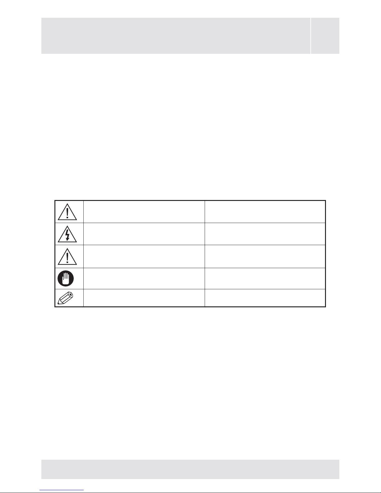
Warning Serious injury or death risk
Risk of electric shock Dangerous voltage risk
Caution Injury or property damage risk
Important Operating the system correctly
Notice Additional notes marked
Page 12

12
PART-2: INSTALLATION AND PREPARATIONS
FOR USE
This modern, functional and practical cooker, that has been
manufactured with parts and materials of the highest quality, will
meet your cooking needs in every aspect. You should read this
manual to avoid a problem and to achive satisfactory results.
The following information details correct installation and service
processes. It must be read especially by the technician who
will install the appliance.
Important: This appliance must be installed by a qualied
person according to the manufacturers installation
instructions, local building regulations, gas authority codes and
electrical wiring instructions.
2.1 Ventilation requirements
For rooms with a volume of less than 5 m3 - permanent ventilation
of 100 cm2 free area is required.
For rooms with a volume of between 5 m3 and 10 m3 a permanent
ventilation of 50 cm2 free area will be required unless the room
has a door which opens directly to outside air, in which case
no permanent ventilation is required.
Air inlet section
minimum 100cm
2
Air inlet section
minimum 100cm
2
Page 13

13
For rooms with a volume greater than 10 m3 - no permanent
ventilation is required.
Pay attention: Regardless of room size, all rooms containing
the appliance must have direct access to the outside air via an
openable window or equivalent.
Emptying of the Burned Gases from Environment
Cooking appliances that operate with gas, throw the burned gas
wastes out directly to the outside or through the cooker hoods
that are connected to the a chimney that opens directly to the
outside. If it seems not possible to install a cooker hood, it is
required to set an electric fan on the window or wall that has
access to fresh air. This electric fan must have the capacity to
change the air of the kitchen environment 4-5 times of its own
volume of air per hour.
Cooker hood
ue
Electrical ventilator
Air inlet section
minimum
100cm
2
Air inlet section
minimum
100cm
2
Page 14

14
2.2 Installation of product
There are some factors to which attention must be paid
while installing your product. Care should be taken. Pay
attention to the following instructions in order to prevent any
problems and/or dangerous situations that may occur later.
The appliance can be placed close to other furniture on condition
that in the area where the oven is set up, the furniture’s height
does not exceed the height of the cooker panel.
Pay attention not to place it near the refrigerator, ammable
or inammable materials such as curtains, cloths, etc. that will
begin to burn quickly.
The furniture close to the product must be manufactured resistant
to temperatures up to 100°C.
If the kitchen furniture is higher than the cooktop, it must be at
least 10cm away from the cooker’s side.
Minimum
42 cm
Min. 65cm
(with hood)
Min. 70cm
(without hood)
COOKER HOOD
Minimum
42 cm
Page 15

15
It is advised that there is a 2cm blank space around the product
for air circulation.
(The minimum distance between the pan support and any wall
cupboards or cooker hoods with a fan over the product, are
shown in the above gure.) The cooker hood must be at minimum
65cm height from the pan support. If there is no cooker hood,
this height must not be less than 70cm.
2.3 Gas connection
Assembly of gas supply and leakage check
The connection of the appliance should be performed in
accordance with local and international standards and regulations
applicable. First check what type of gas should be installed to
the cooker. This information is given by a sticker on the back of
the cooker. You can nd the information related to appropriate
gas types and appropriate gas injectors on the technical data
table. Check that the feeding gas pressure is compliant with
values on the technical data table, to get maximum efciency
and to ensure the least consumption. If the pressure of used
gas is different to the values stated or not stable in your area,
it may be necessary to assemble pressure regulator on the gas
inlet. It is essential that you contact an authorized service agent
to make these adjustments.
The points that must be checked during exible hose assembly
If the gas connection is made by a exible hose that is xed on
the gas inlet of the appliance, it must be xed by a pipe collar.
Page 16

16
Connect your appliance with a short and durable hose that is
as close as possible to the gas source.
The hose’s permitted maximum length is 1.5m. The hose that
brings gas to the appliance must be changed once a year for
your safety.
The hose must be kept clear from areas that may heat up to
temperatures in excess of 900C. The hose must not be ruptured,
bent or folded. It must be kept clear of sharp corners, moving
objects and should not be defective. Before assembly, it must
be checked for any production defect.
As gas is turned on, all connection parts and hoses must be
checked with soapy water or leakage uids. No bubble should
appear. If there are bubbles, check the connection joint and
redo the test. Do not use naked ame to check for gas leaks. All
metal components used for the gas connection must be clear
of rust. Also check the expiry dates of components to be used.
The points that must be checked during xed gas connection
assembly
To assemble a xed gas connection (gas connection made by
threads, e.g. a nut), there are different methods used in different
countries. The most common parts are already supplied with
your appliance. Any other part can be supplied as a spare part.
During connections, always keep the nut on the gas manifold
xed, while rotating the counter-part. Use appropriately sized
spanners for a safe connection. For all surfaces between different
Page 17

17
components, always use the seals provided in the gas conversion
kit. The seals used during connection should also be approved
to be used in gas connections. Do not use plumbing seals for
gas connections.
Remember that this appliance is ready to be connected to the
gas supply in the country for which it has been produced. The
main country of destination is marked on the rear cover of the
appliance. If you need to use it in another country, any of the
connections in the gure below can be required. In such a case,
contact local authorities to learn the correct gas connection.
Gas Pipe
Gas Pipe
Gas Pipe
Gas Pipe
Seal
Seal
Seal
Hose
Fitting
Adapter
Adapter
Gas Hose
with Collar
Mechanical
Gas Hose
Mechanical
Gas Hose
Mechanical
Gas Hose
It is required that an authorized service agent makes the
appropriate gas connections in compliance with safety standards.
ATTENTION! Do not use any match or lighter to check for
gas leaks.
Changing the gas inlet
For some countries, the gas inlet type can be different for NG/LPG
gases. In such a case, remove the current connection components
and nuts (if any) and connect the new gas supply accordingly. In
all conditions, all components used in gas connections should
be approved by local and/or international authorities. In all gas
Page 18

18
connections, refer to the “Assembly of gas supply and leakage
check” clause explained before.
Anti-Tilting Kit
Anti-Tilting Bracket (x1)
(Will be installed to the
wall)
Adaptor (x1)
(Installed on the product)
The document bag contains an anti-tilting kit. Anti-tilting bracket
(1) should be removed from the kit and installed onto the wall
with the following measures. The adaptor (2) that will provide
connection of the anti-tilting bracket to the oven is preinstalled to
the oven with 4 screws. The height can be adjusted by loosening
the 4 screws of the adaptor. After installation of the anti-tinting
bracket to the wall, push the product up to wall and check if the
bracket is placed on the cut out on the adaptor.
Page 19

19
Page 20

20
Anti-Tilting Bracket Ground
Mounting Information
PRODUCT THE MODEL A B
60x60
50x60
85 cm product 57 53,7
90 cm product 53 48,2
50x50
85 cm product 57 39,4
90 cm product 53 33,9
The anti-tilting bracket is screwed on the
ground in the shown dimensions. The
product is xed to the anti-tilting bracket
by its adjustable foot.
Page 21

21
2.4 Gas conversion
Caution: The following procedures must be undertaken by
authorized service people.
Your appliance is adjusted to be operated with LPG/NG gas.
The gas burners can be adapted to different types of gas, by
replacing the corresponding injectors and adjusting the minimum
ame length suitable to the gas in use. For this purpose, the
following steps should be performed;
Changing injectors
Hob Burners
Cut off the main gas supply and unplug from the electric mains.
Remove the burner caps and the adapters.
Unscrew the injectors. For this, use a 7mm spanner.
Replace the injector with the ones from the gas conversion kit,
with corresponding diameters suitable to the type of gas that
is going to be used, according to the information chart (which
is also supplied in the gas conversion kit).
Page 22

22
Grill Injectors
The grill injector is assembled by a single screw that is placed
on the tip of the burner. This screw is already visible. Remove
the screw, pull the grill burner to yourself and you will see the
injector revealed on the rear surface of the oven cavity.
Remove the injectors with a 7mm spanner and replace the
injector with the ones from the spare set,
with corresponding diameters suitable to
the type of gas that is going to be used,
according to the information chart (which
is supplied in the gas conversion kit).
Spanner
Injector
Screw
Grill burner
Page 23

23
Oven Injector
The oven burner is xed in its cradle by a single clip that is placed
on the left-hand side of the burner. Pull the clip (Figure 6) further
left, and with your other hand, lift the burner up holding from
the thermocouple/spark plug holder. The injector is placed on
the right side of the burner cradle. Repeat the same procedure
for both Main and Top Oven (if present) burners.
Remove the injectors with a 7mm spanner and replace the
injector with the ones from the spare set, with corresponding
diameters suitable to the type of gas that is going to be used,
according to the information chart (which is also supplied in the
gas conversion kit).
Clip
Page 24

24
Adjusting the minimum ame position
The ame length in the minimum position is adjusted with a
at screw located on the valve. For valves with a ame failure
device, the screw is located on the side of the valve spindle.
For valves without a ame failure device, the screw is located
inside the valve spindle. For easier reduced ame adjustment,
it is advised to remove the control panel (and microswitch, if
present) during adjustment.
To determine the minimum position, ignite the burners and
leave them on in the minimum position. With the help of a
small screwdriver fasten or loosen the bypass screw around
90 angular degrees. When the ame has a length of at least
4mm, the gas is well distributed. Make sure that the flame
does not die out when passing from the maximum position to
the minimum position. Create an articial wind with your hand
toward the ame to see if the ames are stable.
Valve with ame failure device
Bypass Screw
Valve without ame failure
device
Screw(inside the hole)
Page 25

25
For the oven burner, operate the oven burner at the minimum
position for 5 minutes, then open and close the oven door 2-3
times to check the ame stability of the burner. You do not need
to reduce the ame size for grill burners.
The position of the bypass screw must be loosened for conversion
from LPG to NG. For conversion from NG to LPG, the same
screw must be fastened. Make sure that the appliance is unpluged
from the electric mains and the gas supply is open.
Changing the gas inlet
For some countries, the gas inlet type can be different for NG/LPG
gases. In such a case, remove the current connection components
and nuts (if any) and connect the new gas supply accordingly. In
all conditions, all components used in gas connections should
be approved by local and/or international authorities. In all gas
connections, refer to the [“Assembly of gas supply and leakage
check”] clause explained before.
Thermostatic oven valve
Bypass Screw
Non-thermostatic oven valve
Bypass Screw
Page 26

26
2.5 Electric connection and safety (If available)
During the electric connection, follow the instructions stated in
the user manual.
The earthing cable must be connected to the earth terminal.
You have to ensure the power cord with suitable insulation is
connected to the power source during the connection. If there
is no appropriate earthed electric outlet in accordance with
regulations in the place where the appliance is to be installed,
contact the authorized service centre. The earthed electric outlet
must be close to the appliance.
Do not use an extension cord.
The power cord must not touch any hot
surface of the product.
In the case of the power cord being
damaged, contact the Authorized Service
centre to have it changed.
Any wrong electric connection may
damage your appliance, as well as endangering your safety,
rendering your guarantee invalid.
The appliance is adjusted for 230V 50Hz electricity. If the mains
electricity is different, contact the authorized service centre.
Page 27

27
The supply cord should be kept away from hot parts of the
appliance. Otherwise, the cord may be damaged, causing a
short circuit.
The manufacturer declares that it has no responsibility against
any kind of damages and losses that are caused by improper
connections that are performed by unauthorized people.
2.6 Adjustment of feet
Your product stands on 4 adjustable
feet. When the product is placed
where it is to be used, check if the
product is balanced. If not, you can
make the adjustment by turning
the feet clockwise as required. It
is possible to raise the appliance
a maximum of 30mm by the
feet. When the feet are adjusted
appropriately, do not move the
appliance by dragging. It should
be lifted to reposition.
Page 28

28
3.1 Cleaning
Be sure that all control switches
are off and your appliance has
cooled before cleaning your oven.
Switch off the appliance. Check
whether cleaning materials are
appropriate and recommended by
the manufacturer before using on
your oven. As they may damage the
surfaces, do not use caustic creams, abrasive cleaning powders,
thick wire wool or hard tools. Should any liquids overow, clean
the overflown liquids immediately to avoid enameled parts
becoming damaged.
Cleaning of oven
The inside of enameled ovens are best cleaned when the oven
is warm. Wipe the oven with a soft cloth that has been soaked
in soapy water after each use. Later re-wipe it with a wet cloth
and dry. It may be required to use a liquid cleaning material
from time to time to completely clean. Do not clean with dry/
powder cleaners or steam cleaners.
Catalytic cleaning (If available)
Catalytic cleaning involves a coating, which is applied to the
oven cavity. The catalytic liners eliminates small grease residues
during cooking at high temperatures. If grease residues remain
after cooking, these can be eliminated by using the oven empty
at 2500C for one hour. There are limitations to the level of the
PART-3: CLEANING AND MAINTENANCE
Page 29

29
clean as it is dependent on where the liners are placed. The
base is enamel and the door window is glass, both of which still
need to be cleaned using household cleaners.
Removal of wire shelf
Removal of catalytic panel
To remove the
wire rack;
Pull the wire
rack as shown in
the picture. After
releasing it from
clips(1),lift it
up(2).
To remove the
catalytic liner;
Remove screws
on the each
catalytic liners.
Cleaning of Glass lid (If available)
In order to be able to clean the glass lid, use a glass cleaner.
Then rinse & dry it with a dry cloth.
Removal of top oven door
To remove the oven door;
1. Open the oven door(1).
2. Open the saddle bracket (with the
aid of a screwdriver, etc.) up to end
position(2).
Page 30

30
3. Close the door until it almost
reaches the full closed position as
shown in 3rd gure and remove the
door by pulling it towards yourself.
Removal of inner glass for prole oven doors
Before cleaning the oven door glass, you must pull out the inner
glass as shown;
Pull the glass towards direction 1 as
shown and release from the holder clip.
Pull out the glass towards direction 2.
After cleaning; place the glass back
into position (towards direction 3) and x the glass in place with
the holder clip (towards direction 4).
Triple glass oven doors
If the oven door is a triple glass oven
door, the third glass also can be pulled
out using the same procedure.
After cleaning; place the glass back
into position, sliding the glass under
the clips in position ‘’A’’, and x into
place under the clips in position ‘’B’’.
B
B
A
A
Page 31

31
NOTE:To re-assemble the door follow the opposite rules
of removal.
Please pay attention that the recessed forms should be
positioned properly on the hinge counterparts as shown on
2nd gure.
Cleaning of Gas Cooker - Hob Part
1. Lift up the pan supports, caps and crowns of hob burners.
2. Wipe and clean the back panel with a soapy cloth.
3. Wash the caps and crowns of hob burners and rinse them.
Do not leave them wet, immediately dry them with paper
cloth.
4. After cleaning, make sure that you re-assemble the parts
correctly.
5. Do not clean any part of the hob with wire wool. It causes
the surface to be scratched.
6. The pan support top surfaces may, in time be scratched
due to usage. In this case, these parts may rust which is
not a production fault.
7. During cleaning of the hob plate, make sure that no water
ows inside the burner cups, as this may block the injectors.
Page 32

32
Burner Caps
Periodically, enameled pan supports, enameled covers and
burner heads must be washed with soapy warm water rinsed
and dried. After drying them thoroughly, replace them correctly.
Hob Surface
Enamelled Parts:
In order to keep them as new, it is necessary to clean them
frequently with mild warm soapy water and then dry with a cloth.
Do not wash them while hot and never use abrasive powders
or abrasive cleaning materials. Do not allow vinegar, coffee,
milk, salt, water, lemon, or tomato juice to remain in contact
with enameled parts for long periods of time.
Stainless Steel
Stainless steel parts must be cleaned frequently with warm,
soapy water and a soft sponge and then dried with a soft cloth.
Do not use abrasive powders or abrasive cleaning materials.
Do not allow vinegar, coffee, milk, salt, water, lemon or tomato
juice to remain in contact with stainless steel parts long periods
of time.
Page 33

33
3.2 Maintenance
Change of Oven Lamp
(If available)
At rst unplug the product from the
electric supply and make sure that
the product is cool. Remove the bulb
after removing the glass lens. Fit
the new bulb (resistant to 300°C) in
place of the bulb that you removed
(230 V, 25 Watt, Type E14). Replace
the glass lens. Your product will then be ready for use.The lamp
design is specic for use in household cooking appliances and
it is not suitable for household room illumination.
Other Controls
Periodically check the gas connection pipe. If even only a small
abnormality is detected, inform the technical service centre to
have it replaced. We recommend that gas connection parts should
be changed once a year. If any abnormality is felt while operating
the control knobs of cooker, contact to the authorized service.
Page 34

34
4.1 Basic troubleshooting before contacting service
If the oven does not operate:
a) The oven may be switched off
b) There may be a power cut
c) The fuse board may have tripped
If the oven does not heat :
The heat may not have been adjusted with the oven’s heater
control switch.
If the interior lighting lamp does not light :
a) Check the Electricity supply to the appliance
b) Change the bulb using the 3.2 guide
Cooking (If lower-upper part does not cook equally):
Check the shelf locations, cooking period and heat values
according to the manual.
The hob burners do not operate correctly :
Check the burner parts are correctly assembled (especially
after cleaning).
The gas supply pressure may be too low/high. For appliances
working with bottled LPG, the LPG cylinder may be depleted.
PART-4: SERVICE AND TRANSPORT
Page 35

35
If after checking as above, you still have any problem with
your product, please call the Authorized Service centre.
4.2 Information related to transport
If you need to transport the product, use the original product
packaging and carry it using its original case. Follow the transport
signs on the packaging. Tape the upper parts, caps and crowns
and pan supports to the cooking panels. Place some paper
between the upper cover and cooking panel, cover the upper
cover, then tape it to the side surfaces of oven. Tape cardboard
or paper onto the interior glass of the oven to prevent the trays
in your oven damaging the oven door during transport. Also
tape the oven door to the side panels.
If you do not have the original packaging; prepare a carriage
box so that the appliance, especially the external surfaces
(glass and painted surfaces) of the oven, are protected against
external threats.
Page 36

The symbol on the product or on its packaging
indicates that this product may not be treated as
household waste. Instead it shall be handed over
to the applicable collection point for the recycling
of electrical and electronic equipment. By ensuring
this product is disposed of correctly, you will help
prevent potential negative consequences for the
environment and human health, which could otherwise
be caused by inappropriate waste handling of this
product. For more detailed information about recyling
of this product, please contact your local city ofce,
your household waste disposal service or the shop
where you purchased the product.
52165685 07/15
 Loading...