

Page 1
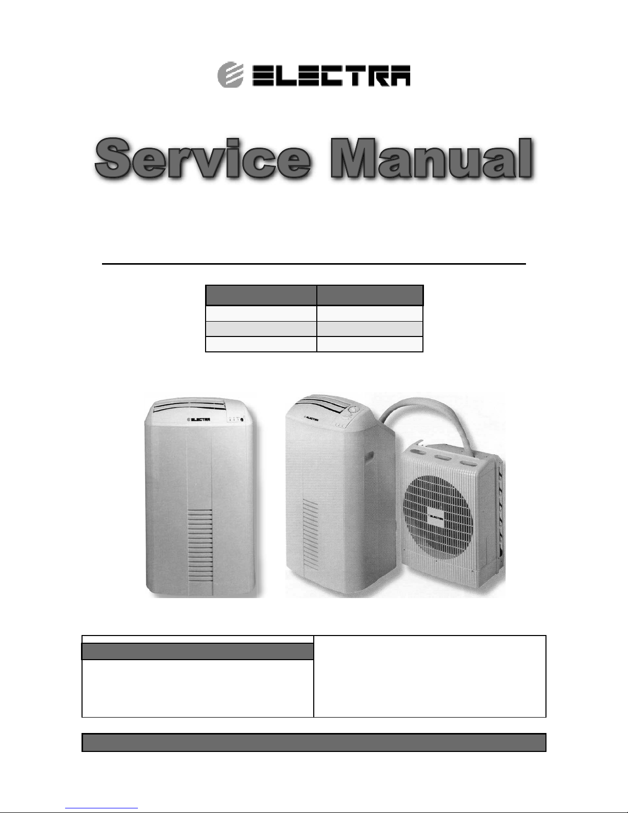
Service Manual
Mobile Series
REFRIGERANT
R410A
COOLING ONLY
HEAT PUMP
JANUARY 2005
Indoor Units Outdoor Units
Monoblock 7 N/A
SP 11 SP 11
SP 16 SP 16
Page 2
A
LIST OF EFFECTIVE PAGES
Revision Y05-01
Service Manual - MOBILE Series
LIST OF EFFECTIVE PAGES
Note: Changes in the pages are indicated by a “Revision#” in the footer of each effected page
(when none indicates no changes in the relevant page). All pages in the following list represent
effected/ non effected pages divided by chapters.
Dates of issue for original and changed pages are:
Original ....... 0 ........ 15 December 2004
Total number of pages in this publication is 131 consisting of the following:
Page
No.
Revision
No. #
Page
No.
Revision
No. #
Page
No.
Revision
No. #
Title ....................... 0
A ........................... 1
i ............................. 0
1-1 - 1-2 ................ 0
2-1 - 2-3 ................ 0
3-1 ........................ 0
4-1 ........................ 0
5-1 - 5-10 .............. 1
6-1 - 6-2 ................ 0
7-1 ........................ 0
8-1 - 8-4 ................ 0
9-1 - 9-2 ................ 0
10-1-10-36 ............ 0
11-1-11-3 ............... 0
12-1-12-62 ............ 0
Appendix -A ...........0
• Zero in this column indicates an original page.
*Due to constant improvements please note that the data on this service manual can be modified with out notice.
**Photos are not contractual
Page 3

i
TABLE OF CONTENTS
Revision Y05-01Service Manual - MOBILE Series
Table of Contents
1. INTRODUCTION ...................................................................................................1-1
2. PRODUCT DATA SHEET ......................................................................................2-1
3. RATING CONDITIONS ..........................................................................................3-1
4. OUTLINE DIMENSIONS .......................................................................................4-1
5. PERFORMANCE DATA & PRESSURE CURVES ................................................5-1
6. SOUND LEVEL CHARACTERISTICS ..................................................................6-1
7. ELECTRICAL DATA ..............................................................................................7-1
8. WIRING DIAGRAMS .............................................................................................8-1
9. REFRIGERATION DIAGRAMS .............................................................................9-1
10. CONTROL SYSTEM .............................................................................................10-1
11. TROUBLESHOOTING ..........................................................................................11-1
12. EXPLODED VIEWS AND SPARE PARTS LISTS .................................................12-1
13. APPENDIX A .........................................................................................................13-1
Page 4
1-1
INTRODUCTION
Revision Y05-01Service Manual - MOBILE Series
1. INTRODUCTION
1.1 General
The Mobile range comprise the ST (cooling only) and RC (heat pump) models, as
follows:
Model
Mode
Monoblock 7 R410A SP11 R410A SP16 R410A
M E M EME
Cooling Only
√ √ √ √√√
Heat Pump
N/A N/A N/A √ N/A √
Electric Heater
N/A √ N/A N/A N/A N/A
* E – Electronic / Remote control Type.
* M –Electro Mechanical control.
The split type units consists indoor and outdoor unit, interconnected by a flexible hose.
The mobiles indoor units are equipped with four castors for easy mobility.
The electronic models are equipped with a Microprocessor control system, giving the
user a choice of local or remote control operation, as well as precise temperature
setting and control,
1.2 Main Features
The Mobile series benefits from the most advanced technological innovations, namely:
• Easy mobility.
• Easy installation, (no spacial installation is Required).
• R410A .
• Microprocessor control (Electronic model only).
• High COP.
• Automatic vertical treated air sweep (Electronic only).
• Pre charged refrigerant system.
• High reliability quick connectors for split models which enables temporary separation
between indoor and outdoor units for a fix installation type (optional).
• Compact dimensions.
1.3 Filtration
The Mobile series presents several types of air filters:
• Easily accessible, and re-usable pre-filters (mesh)
• Carbon and electrostatic filter (optional)
Page 5
1-2
INTRODUCTION
Revision Y05-01 Service Manual - MOBILE Series
1.4 Control
Electronic model: a microprocessor indoor controller, and an infrared remote control,
supplied as standard, provides complete operating function and programming.
Mechanical model: Electro mechanical control .
For further details please refer to the Installation and Operation Manual, Appendix A.
1.5 Inbox Documentation
Each unit is supplied with its own installation and operation manuals.
Page 6
2-1
PRODUCT DATA SHEET
Revision Y05-01Service Manual - MOBILE Series
2. PRODUCT DATA SHEET
2.1 R410A
Model Indoor Unit Monoblock 7 R410A
Model Outdoor Unit N/A
Installation Method of Pipe N/A
Characteristics Units Cooling
Capacity
(1)
Btu/hr 7850
kW 2.30
Power input
(1)
kW 0.95
EER (Cooling) or COP(Heating)
(1)
W/W 2.42
Energy efficiency class B
Power supply V/Ph/Hz 220-240V/Single/50Hz
Rated current A 4.3
Starting current A 17
Circuit breaker rating A 10
INDOOR
Fan type & quantity Centrifugalx1
Fan speeds H/M/L RPM 1390/1280/1170
Air flow
(2)
H/M/L m3/hr 275/257/234
External static pressure Min-Max Pa 0
Sound power level
(3)
H/M/L dB(A) 63/62.5/61.5
Sound pressure level
(4)
H/M/L dB(A) 49/48/47
Moisture removal l/hr 0.9
Condensate drain tube I.D mm 11.5
Dimensions WxHxD mm 470x800x360
Weight kg 32
Package dimensions WxHxD mm 550*450*935
Packaged weight kg 37.5
Units per pallet units 8
Stacking height units 2 levels
OUTDOOR
Refrigerant control Capillary tube
Compressor type, model Rotary,Sanyo C-1RV096H1A
Fan type & quantity N/A
Fan speeds H/L RPM N/A
Air flow H/L m3/hr N/A
Sound power level H/L dB(A) N/A
Sound pressure level
(4)
H/L dB(A) N/A
Dimensions WxHxD mm N/A
Weight kg N/A
Package dimensions WxHxD mm N/A
Packaged weight kg N/A
Units per pallet Units N/A
Stacking height units N/A
Refrigerant type R410A
Refrigerant chargless distance kg/m 0.51kg
Additional charge per 1 meter g/m N/A
Connections between
units
Liquid line In.(mm) N/A
Suction line In.(mm) N/A
Max.tubing length m. N/A
Max.height difference m. N/A
Operation control type Remote control or Rotary switch control
Heating elements kW 2 (Electronic model only)
Others
(1) Rating conditions in accordance with ISO 5151 and ISO 13253 (for ducted units) and EN 14511.
(2) Airflow in ducted units; at nominal external static pressure.
(3) Sound power in ducted units is measured at air discharge.
(4) Sound pressure level measured at 1 meter distance from unit.
Page 7
2-2
PRODUCT DATA SHEET
Revision Y05-01 Service Manual - MOBILE Series
Model Indoor Unit SP11 R410A
Model Outdoor Unit SP11 R410A
Installation Method of Pipe Installed already or Quick connector
Characteristics Units Cooling only Cooling Heating
Capacity
(1)
Btu/hr 10300 10300 11600
kW 3.02 3.02 3.4
Power input
(1)
kW 0.977 0.977 0.95
EER (Cooling) or COP(Heating)
(1)
W/W 3.09 3.09 3.58
Energy efficiency class
B
BB
Power supply V/Ph/Hz 220-240V/Single/50Hz
Rated current A 4.5 4.5 4.3
Starting current A 18
Circuit breaker rating A 10
INDOOR
Fan type & quantity Centrifugalx1
Fan speeds H/M/L RPM 1280/1170/920
Air flow
(2)
H/M/L m3/hr 503/451/335
External static
pressure
Min-Max Pa 0
Sound power level
(3)
H/M/L dB(A) 62/60/57
Sound pressure level
(4)
H/M/L dB(A) 48/46/43
Moisture removal l/hr 1.25
Condensate drain tube I.D mm 11.5
Dimensions WxHxD mm 470x800x360
Weight kg 33 34.5
Package dimensions WxHxD mm 650x860x550
Packaged weight kg 55 56.5
Units per pallet units 4
Stacking height units 2 levels
OUTDOOR
Refrigerant control Capillary tube
Compressor type, model Rotary, HITACHI ASG108CV-B7AT
Fan type & quantity Propeller(direct) x 1
Fan speeds H/L RPM 1080
Air flow H/L m3/hr N/A
Sound power level H/L dB(A) 69
Sound pressure level
(4)
H/L dB(A) 62
Dimensions WxHxD mm 440*540*320
Weight kg 17
Package dimensions WxHxD mm In the same package of INDOOR
Packaged weight kg See INDOOR
Units per pallet Units See INDOOR
Stacking height units See INDOOR
Refrigerant type R410A
Refrigerant chargless distance kg/m 0.99kg/3m 1.04kg/3m
Additional charge per 1 meter g/m N/A
Connections between
units
Liquid line In.(mm) 3/16(4.76)
Suction line In.(mm) 1/2(12.7)
Tubing length m. 3
Max.height
difference
m. 1.6
Operation control type Remote control or Rotary switch control (5)
Heating elements kW N/A
Others
(1) Rating conditions in accordance with ISO 5151 and ISO 13253 (for ducted units) and EN 14511.
(2) Airflow in ducted units; at nominal external static pressure.
(3) Sound power in ducted units is measured at air discharge.
(4) Sound pressure level measured at 1 meter distance from unit.
Page 8

2-3
PRODUCT DATA SHEET
Revision Y05-01Service Manual - MOBILE Series
Model Indoor Unit SP16 R410A
Model Outdoor Unit SP16 R410A
Installation Method of Pipe Installed already or Quick connector
Characteristics Units Cooling only Cooling Heating
Capacity
(1)
Btu/hr 14230 14230 15660
kW 4.17 4.17 4.59
Power input
(1)
kW 1.544 1.544 1.387
EER (Cooling) or COP(Heating)
(1)
W/W 2.70 2.70 3.31
Energy efficiency class
D
DC
Power supply V/Ph/Hz 220-240V/Single/50Hz
Rated current A 7.1 7.1 6.3
Starting current A 28
Circuit breaker rating A 15
INDOOR
Fan type & quantity Centrifugalx1
Fan speeds H/M/L RPM 1360/1290/1126
Air flow
(2)
H/M/L m3/hr 433/401/356
External static
pressure
Min-Max Pa 0
Sound power level
(3)
H/M/L dB(A) 64/63.5/61
Sound pressure level
(4)
H/M/L dB(A) 51/50/48
Moisture removal l/hr 1.8
Condensate drain tube I.D mm 11.5
Dimensions WxHxD mm 470x800x360
Weight kg 38 39.5
Package dimensions WxHxD mm 650x860x550
Packaged weight kg 60 61.5
Units per pallet units 4
Stacking height units 2 levels
OUTDOOR
Refrigerant control Capillary tube
Compressor type, model Rotary, Sanyo C-RV168H1A
Fan type & quantity Propeller(direct) x 1
Fan speeds H/L RPM 1080
Air flow H/L m3/hr N/A
Sound power level H/L dB(A) 69
Sound pressure level
(4)
H/L dB(A) 62
Dimensions WxHxD mm 440*540*320
Weight kg 17
Package dimensions WxHxD mm In the same package of INDOOR
Packaged weight kg See INDOOR
Units per pallet Units See INDOOR
Stacking height units See INDOOR
Refrigerant type R410A
Refrigerant chargless distance kg/m 1.13kg/3m 1.16kg/3m
Additional charge per 1 meter g/m N/A
Connections between
units
Liquid line In.(mm) 3/16(4.76)
Suction line In.(mm) 1/2(12.7)
Tubing length m. 3
Max.height
difference
m. 1.6
Operation control type Remote control or Rotary switch control (5)
Heating elements kW N/A
Others
(1) Rating conditions in accordance with ISO 5151 and ISO 13253 (for ducted units) and EN 14511.
(2) Airflow in ducted units; at nominal external static pressure.
(3) Sound power in ducted units is measured at air discharge.
(4) Sound pressure level measured at 1 meter distance from unit.
Page 9
3-1
RATING CONDITIONS
Revision Y05-01Service Manual - MOBILE Series
3. RATING CONDITIONS
Standard conditions in accordance with ISO 5151.
For Split unit
Cooling:
Indoor: 27oC DB 19oC WB
Outdoor: 35 oC DB
Heating:
Indoor: 20oC DB
Outdoor: 7oC DB 6oC WB
For monoblock (EN14511)
Standard condition: 35oC DB 24oC WB
Application condition: 27oC DB 19oC WB
3.1 Operating Limits
3.1.1 Monoblock 7
Indoor
Cooling
Upper limit 35
o
C DB 24oC WB
Lower limit 21
o
C DB 15oC WB
Voltage
1PH
198 – 264 V
3.1.2 SP11/16
Indoor Outdoor
Cooling
Upper limit 32
o
C DB 23oC WB 46oC DB
Lower limit 21oC DB 15oC WB 21oC DB
Heating
Upper limit 27
o
C DB 24oC DB 18oC WB
Lower limit 10
o
C DB -9oC DB -10oC WB
Voltage
1PH
198 – 264 V
Page 10
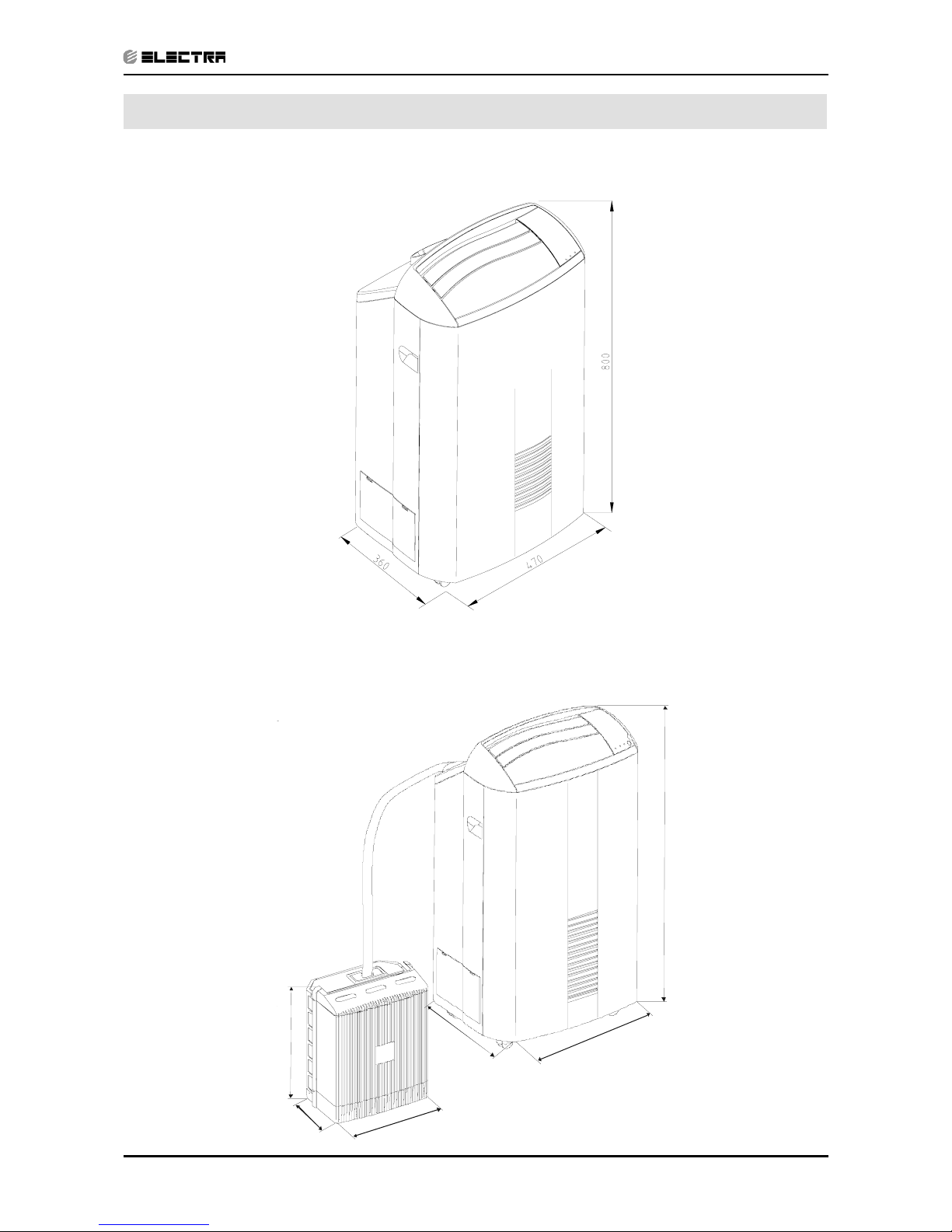
4-1
OUTLINE DIMENSIONS
Revision Y05-01Service Manual - MOBILE Series
4. OUTLINE DIMENSIONS
4.1 Monoblock 7
4.2
SP 11/16
4
3
6
0
4
7
0
8
0
0
4
0
5
4
0
3
2
0
Page 11
5-1
PERFORMANCE DATA & PRESSURE CURVES
Revision Y05-01Service Manual - MOBILE Series
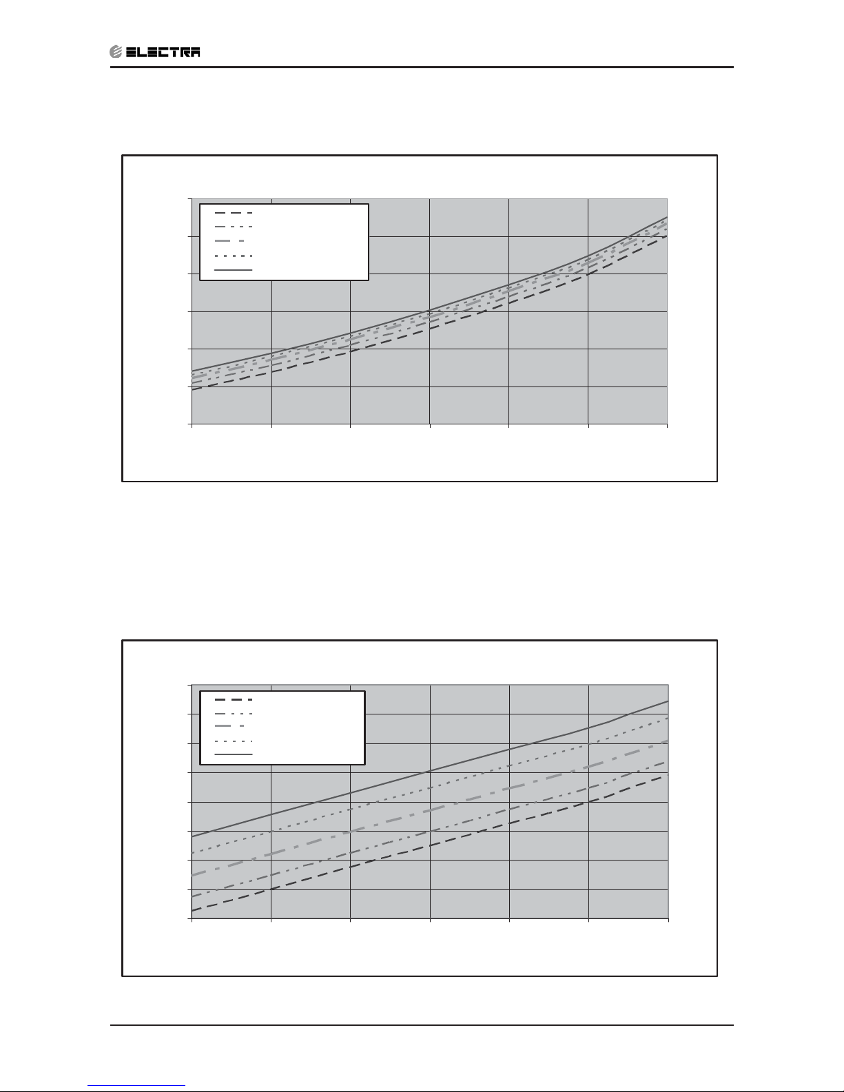
5. PERFORMANCE DATA & PRESSURE CURVES
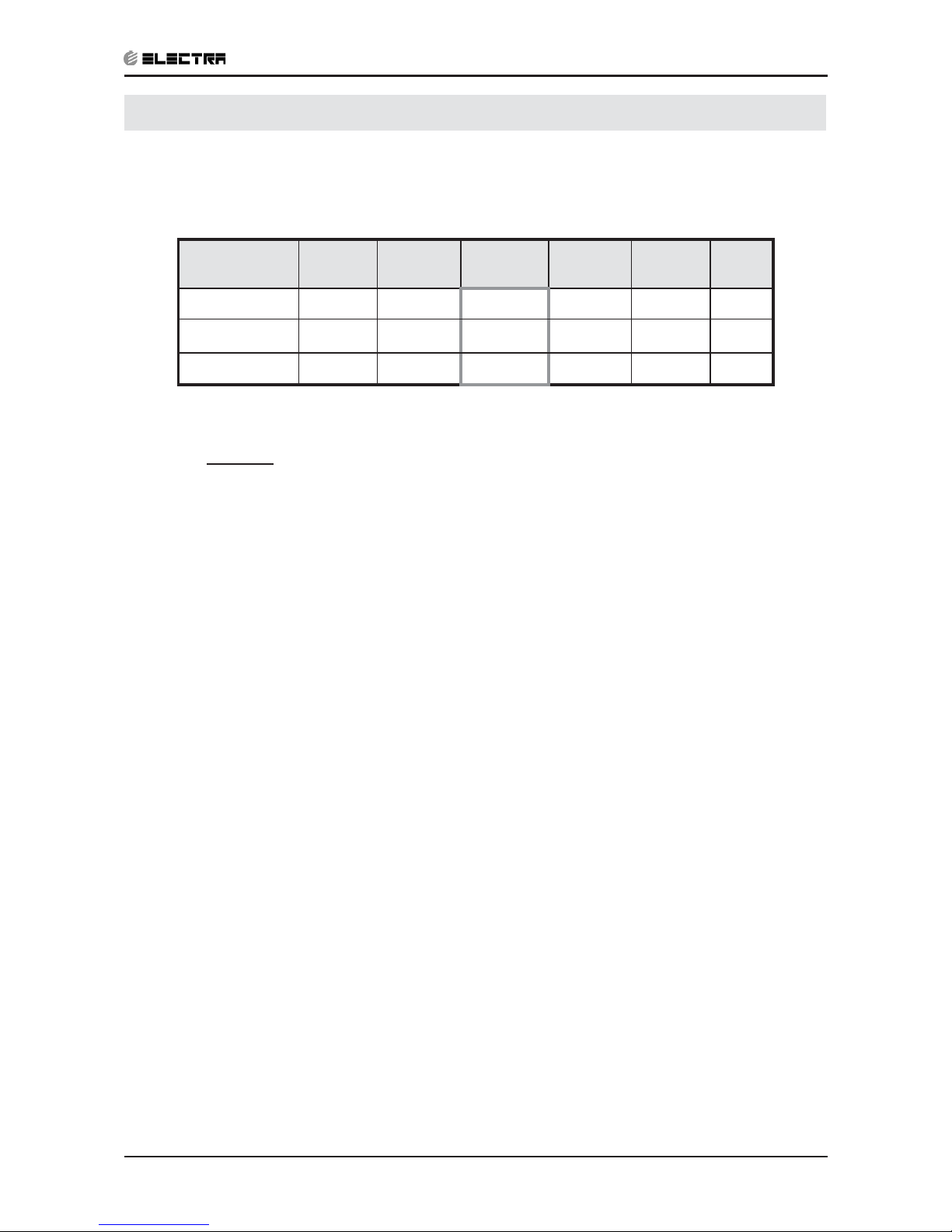
5.1 Monoblock 7
5.1.1 Cooling Capacity (kW)
Entering Air
WB/DB (
o
C)
15/21 17/24
19/27
21/29 23/32 24/35
TC 2.20 2.24
2.30
2.36 2.30 2.29
SC 1.38 1.41 1.47 1.42 1.38 1.56
PI 0.81 0.90 0.95 0.98 1.09 1.14
*indoor and outdoor air inlet temp’ are equal for monoblock type
LEGEND
TC – Total Cooling Capacity, kW
SC – Sensible Capacity, kW
PI – Power Input, kW
WB – Wet Bulb Temp., (
o
C)
DB – Dry Bulb Temp., (
o
C)
Page 12
5-2
PERFORMANCE DATA & PRESSURE CURVES
Revision Y05-01 Service Manual - MOBILE Series
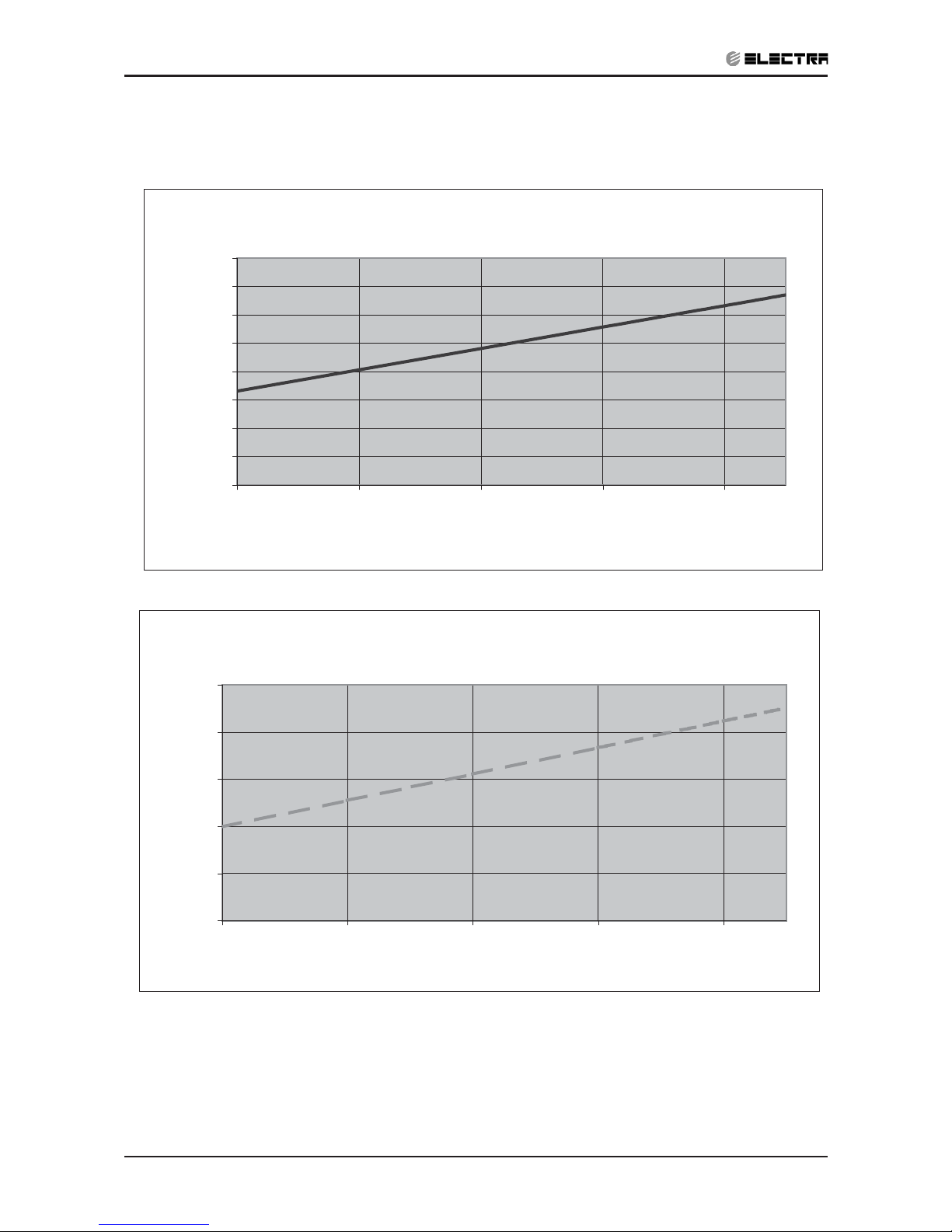
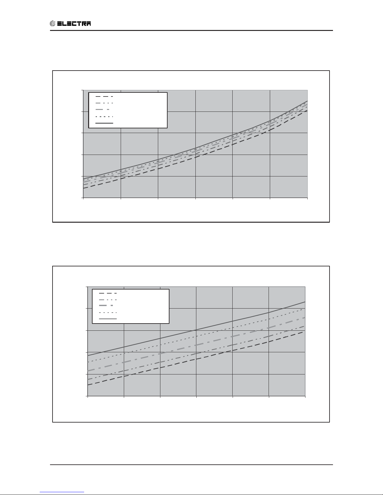
5.2 Pressure Curves
5.2.1 Cooling
Temp
15 17 19 21 23 24
Disch 29.9 32.7 35.5 38.3 41.1 42.5
Suction Pressure Vs. Condensing Inlet Air Temp'
4
5
6
7
8
9
10
11
12
15 17 19 21 23
Inlet Condensing Air Temp'( WB ºC)
Suction Pressure (Bar[g]
Discharge Pressure Vs. Condensing Inlet Air Temp'
20
25
30
35
40
45
15 17 19 21 23
Inlet Condensing Air Temp'( WB ºC)
Discharge Pressure (Bar[g]
Page 13
5-3
PERFORMANCE DATA & PRESSURE CURVES
Revision Y05-01Service Manual - MOBILE Series
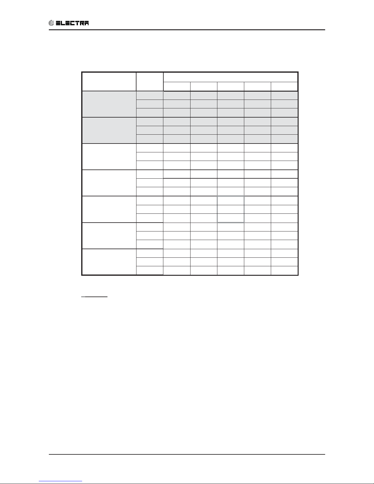
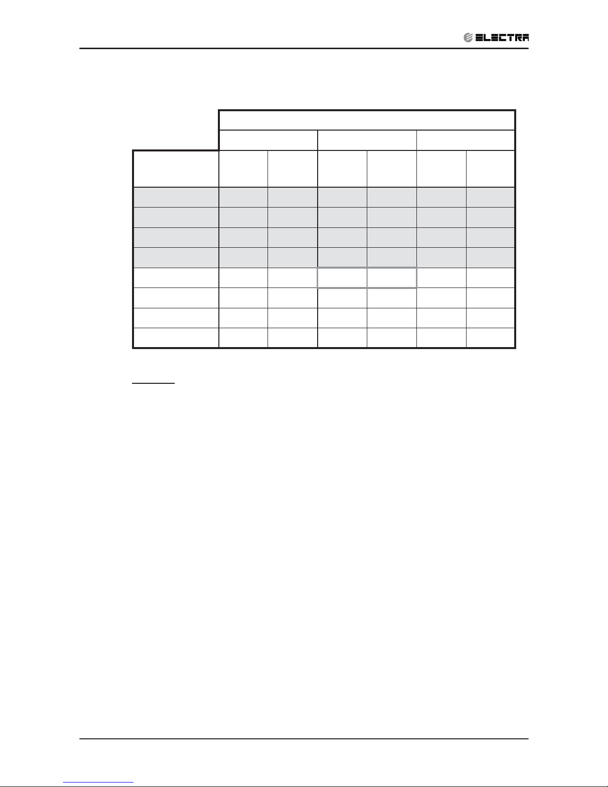
5.3 SP11 R410A
5.3.1 Cooling Capacity (kW)
ENTERING AIR
DB OU Coil(
o
C)
Data
ENTERING AIR WB/DB ID Coil(
o
C)
15/21 17/24 19/27 21/29 23/32
15
TC
3.18 3.30 3.37 3.45 3.51
SC 2.09 2.18 2.26 2.32 2.36
PI
0.69 0.70 0.70 0.70 0.70
20
TC
3.08 3.25 3.35 3.43 3.50
SC 2.04 2.16 2.25 2.31 2.35
PI
0.75 0.76 0.76 0.76 0.76
25
TC
2.91 3.15 3.31 3.41 3.49
SC 1.99 2.11 2.23 2.29 2.34
PI
0.82 0.82 0.83 0.83 0.84
30
TC
2.73 2.97 3.21 3.32 3.42
SC 1.93 2.05 2.18 2.24 2.29
PI
0.88 0.89
0.90
0.91 0.92
35
TC
2.52 2.74
3.02
3.17 3.32
SC 1.83 1.97 2.13 2.19 2.23
PI
0.95 0.96
0.98
0.99 0.99
40
TC
2.29 2.50
1.16
2.98 3.13
SC 1.73 1.86 2.01 2.08 2.12
PI
1.02 1.04 1.06 1.07 1.08
46
TC
1.99 2.18 2.39 2.64 2.85
SC 1.59 1.71 1.84 1.90 1.94
PI
1.12 1.13 1.16 1.18 1.19
LEGEND
TC – Total Cooling Capacity, kW
SC – Sensible Capacity, kW
PI – Power Input, kW
WB – Wet Bulb Temp., (
o
C)
DB – Dry Bulb Temp., (
o
C)
ID – Indoor
OU – Outdoor
(1) Marked area is below standard operating limits.
Page 14
5-4
PERFORMANCE DATA & PRESSURE CURVES
Revision Y05-01 Service Manual - MOBILE Series
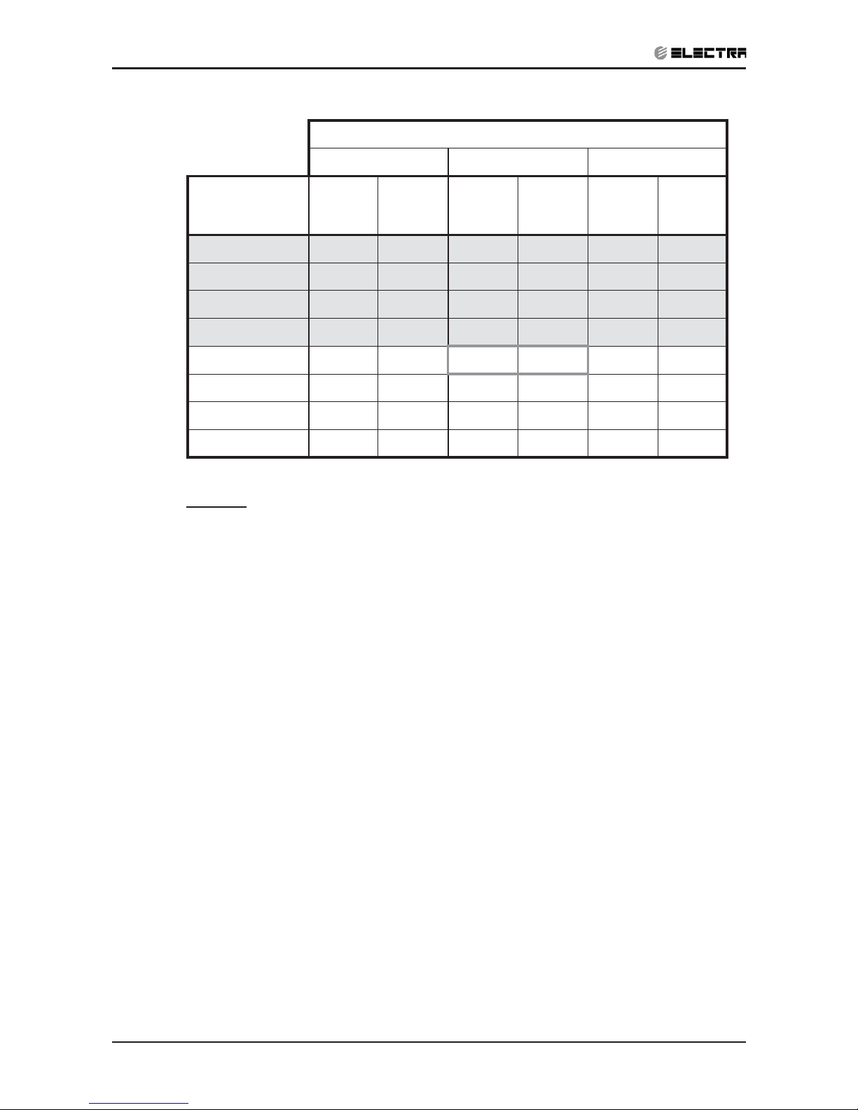
5.3.2 Heating Capacity (kW)
ENTERING AIR DB ID COIL(OC)
15 20 25
ENTERING
WB OU
COIL(
o
C)
TH Pl TH Pl TH Pl
-10 1.79 0.76 1.72 0.81 1.65 0.85
-7 1.92 0.78 1.85 0.82 1.79 0.87
-2 2.04 0.79 1.97 0.84 1.90 0.88
2 2.48 0.83
2.38 0.88
2.28 0.93
6 3.50 0.89 3.40 0.95 3.28 1.01
10 3.81 0.94
3.71 1.00
3.60 1.07
15 4.11 0.98 4.01 1.05 3.91 1.12
20 4.34 1.01 4.23 1.09 4.11 1.18
LEGEND
TH – Total Heating Capacity, kW
PI – Power Input, kW
WB – Wet Bulb Temp., (
o
C)
DB – Dry Bulb Temp., (
o
C)
ID – Indoor
OU – Outdoor
Page 15
5-5
PERFORMANCE DATA & PRESSURE CURVES
Revision Y05-01Service Manual - MOBILE Series
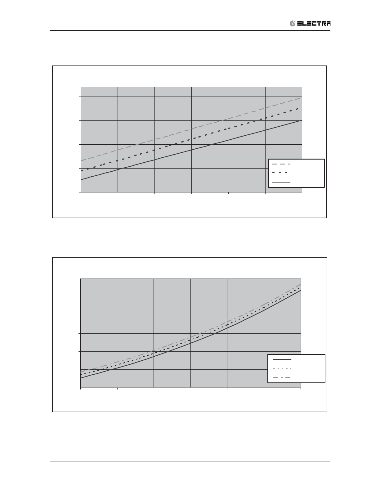
5.4 Pressure Curves
5.4.1 Cooling
Discharge Pressure VS.Outdoor Temp
15
20
25
30
35
40
15 20 25 30 35 40 46
Outdoor Temp.(DB oC )
Discharge Pressure (Bar[g])
15/21(WB/DB ºC)
17/24(WB/DB ºC)
19/27(WB/DB ºC)
21/29(WB/DB ºC)
23/32(WB/DB ºC)
Suction Pressure VS.Outdoor Temp
6.5
7.5
8.5
9.5
10.5
11.5
15 20 25 30 35 40 46
Outdoor Temp.(DB oC )
Suction Pressure (Bar[g])
15/21(WB/DB ºC)
17/24(WB/DB ºC)
19/27(WB/DB ºC)
21/29(WB/DB ºC)
23/32(WB/DB ºC)
Page 16
5-6
PERFORMANCE DATA & PRESSURE CURVES
Revision Y05-01 Service Manual - MOBILE Series
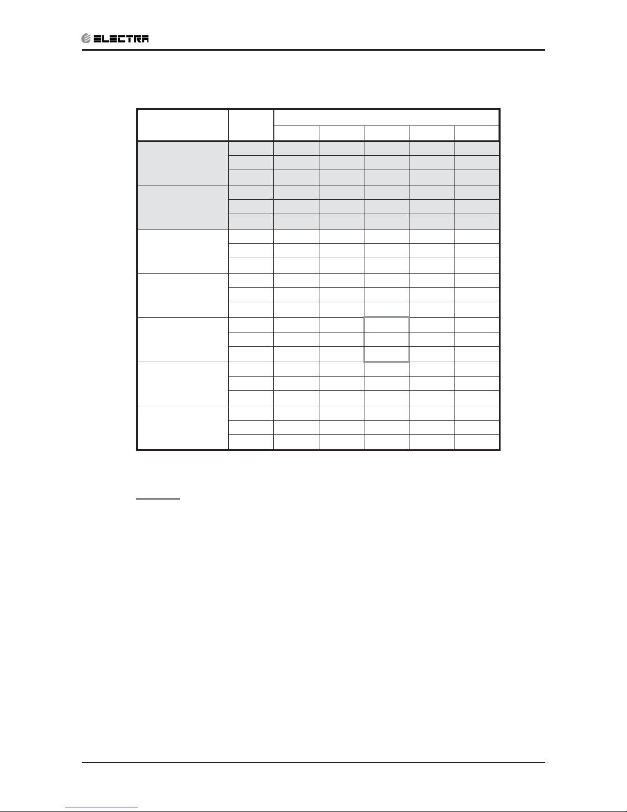
5.4.2 Heating
Discharge Pressure VS.Outdoor Temp
20
22
24
26
28
30
32
34
36
38
-10 -5 0 5 10 15 20
Outdoor Temp.( WB oC )
Discharge Pressure(Bar[g])
25 DB (ºC)
20 DB (ºC)
15 DB (ºC)
Suction Pressure VS.Outdoor Temp
4.0
5.0
6.0
7.0
8.0
9.0
10.0
-10 -5 0 5 10 15 20
Outdoor Temp.( WB oC )
Suction Pressure(Bar[g])
15 DB (ºC)
20 DB (ºC)
25 DB (ºC)
Page 17
5-7
PERFORMANCE DATA & PRESSURE CURVES
Revision Y05-01Service Manual - MOBILE Series
5.5 SP16 R410A
5.5.1 Cooling Capacity (kW)
ENTERING AIR
DB OU Coil(
o
C)
Data
ENTERING AIR WB/DB ID Coil(
o
C)
15/21 17/24 19/27 21/29 23/32
15
TC 4.40 4.55 4.66 4.77 4.84
SC 2.64 2.76 2.86 2.94 2.99
PI 1.09 1.09 1.10 1.10 1.10
20
TC 4.25 4.48 4.62 4.73 4.83
SC 2.59 2.73 2.85 2.93 2.98
PI 1.19 1.19 1.19 1.20 1.20
25
TC 4.02 4.34 4.57 4.71 4.82
SC 2.53 2.68 2.83 2.91 2.96
PI 1.28 1.29 1.30 1.31 1.32
30
TC 3.76 4.10 4.43 4.58 4.72
SC 2.45 2.60 2.76 2.84 2.90
PI 1.38 1.40
1.41
1.43 1.44
35
TC 3.48 3.78
4.17
4.38 4.59
SC 2.33 2.49 2.70 2.78 2.83
PI 1.49 1.52
1.54
1.55 1.56
40
TC 3.17 3.45
1.16
4.11 4.33
SC 2.19 2.36 2.55 2.64 2.69
PI 1.61 1.63 1.66 1.68 1.70
46
TC 2.75 3.00 3.30 3.65 3.93
SC 2.02 2.16 2.33 2.41 2.46
PI
1.76 1.78 1.82 1.85 1.87
LEGEND
TC – Total Cooling Capacity, kW
SC – Sensible Capacity, kW
PI – Power Input, kWה
WB – Wet Bulb Temp., (
o
C)
DB – Dry Bulb Temp., (
o
C)
ID – Indoor
OU – Outdoor
(1) Marked area is below standard operating limits.
Page 18
5-8
PERFORMANCE DATA & PRESSURE CURVES
Revision Y05-01 Service Manual - MOBILE Series
5.5.2 Heating Capacity (kW)
ENTERING AIR DB ID COIL(Oc)
15 20 25
ENTERING
WB OU
COIL(
o
C)
TH Pl TH Pl TH Pl
-10 2.41 1.11 2.32 1.18 2.23 1.24
-7 2.59 1.14 2.50 1.20 2.41 1.26
-2 2.75 1.15 2.66 1.22 2.57 1.29
2 3.35 1.21
3.21 1.28
3.08 1.36
6 4.73 1.30 4.59 1.39 4.43 1.47
10 5.14 1.37
5.00 1.46
4.87 1.56
15 5.55 1.43 5.42 1.54 5.28 1.64
20 5.85 1.47 5.71 1.60 5.55 1.72
LEGEND
TH – Total Heating Capacity, kW
PI – Power Input, kW
WB – Wet Bulb Temp., (
o
C)
DB – Dry Bulb Temp., (
o
C)
ID – Indoor
OU – Outdoor
Page 19
5-9
PERFORMANCE DATA & PRESSURE CURVES
Revision Y05-01Service Manual - MOBILE Series
5.6 Pressure Curves
5.6.1 Cooling
Discharge Pressure VS.Outdoor Temp
15
20
25
30
35
40
45
15 20 25 30 35 40 46
Outdoor Temp.(DB oC )
Discharge Pressure (Bar[g])
15/21(WB/DB ºC)
17/24(WB/DB ºC)
19/27(W B/DB ºC)
21/29(W B/DB ºC)
23/32(W B/DB ºC)
Suction Pressure VS.Outdoor Temp
6.5
7.0
7.5
8.0
8.5
9.0
9.5
10.0
10.5
15 20 25 30 35 40 46
Outdoor Temp.(DB oC )
Suction Pressure (Bar[g])
15/21(WB/DB ºC)
17/24(WB/DB ºC)
19/27(WB/DB ºC)
21/29(WB/DB ºC)
23/32(WB/DB ºC)
Page 20
5-10
PERFORMANCE DATA & PRESSURE CURVES
Revision Y05-01 Service Manual - MOBILE Series
5.6.2 Heating
Discharge Pressure VS.Outdoor Temp
20
25
30
35
40
-10 -5 0 5 10 15 20
Outdoor Temp.( WB oC )
Discharge Pressure(Bar[g])
25 DB (ºC)
20 DB (ºC)
15 DB (ºC)
Suction Pressure VS.Outdoor Temp
3.5
4.5
5.5
6.5
7.5
8.5
9.5
-10 -5 0 5 10 15 20
Outdoor Temp.( WB oC )
Suction Pressure(Bar[g])
15 DB (ºC)
20 DB (ºC)
25 DB (ºC)
Page 21
6-1
SOUND LEVEL CHARACTERISTICS
Revision Y05-01Service Manual - MOBILE Series
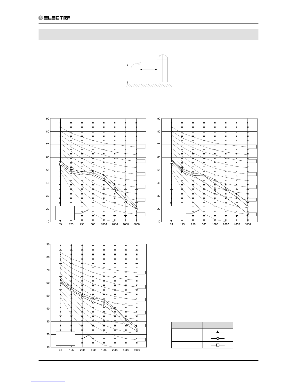
6. SOUND LEVEL CHARACTERISTICS
6.1 Sound Pressure Level
6.2 Soud Pressure Level Spectrum (Measured as Figure 1)
Monoblock 7 SP 11
FAN SPEED LINE
HI
ME
LO
0.9m
microphone
1m
Fig.1 Monoblock
BAND CENTER FREQUENCIES, Hz
APPROXIMATE
THRESHOLD OF
HEARING FOR
CONTINUOUS
NOISE
NC-70
NC-60
NC-50
NC-40
NC-30
NC-20
OCTAVE BAND SOUND PRESSURE LEVEL, dB re 0.002 MICRO BAR
BAND CENTER FREQUENCIES, Hz
APPROXIMATE
THRESHOLD OF
HEARING FOR
CONTINUOUS
NOISE
NC-70
NC-60
NC-50
NC-40
NC-30
NC-20
OCTAVE BAND SOUND PRESSURE LEVEL, dB re 0.002 MICRO BAR
BAND CENTER FREQUENCIES, Hz
APPROXIMATE
THRESHOLD OF
HEARING FOR
CONTINUOUS
NOISE
NC-70
NC-60
NC-50
NC-40
NC-30
NC-20
OCTAVE BAND SOUND PRESSURE LEVEL, dB re 0.002 MICRO BAR
SP 16
Page 22
6-2
SOUND LEVEL CHARACTERISTICS
Revision Y05-01 Service Manual - MOBILE Series
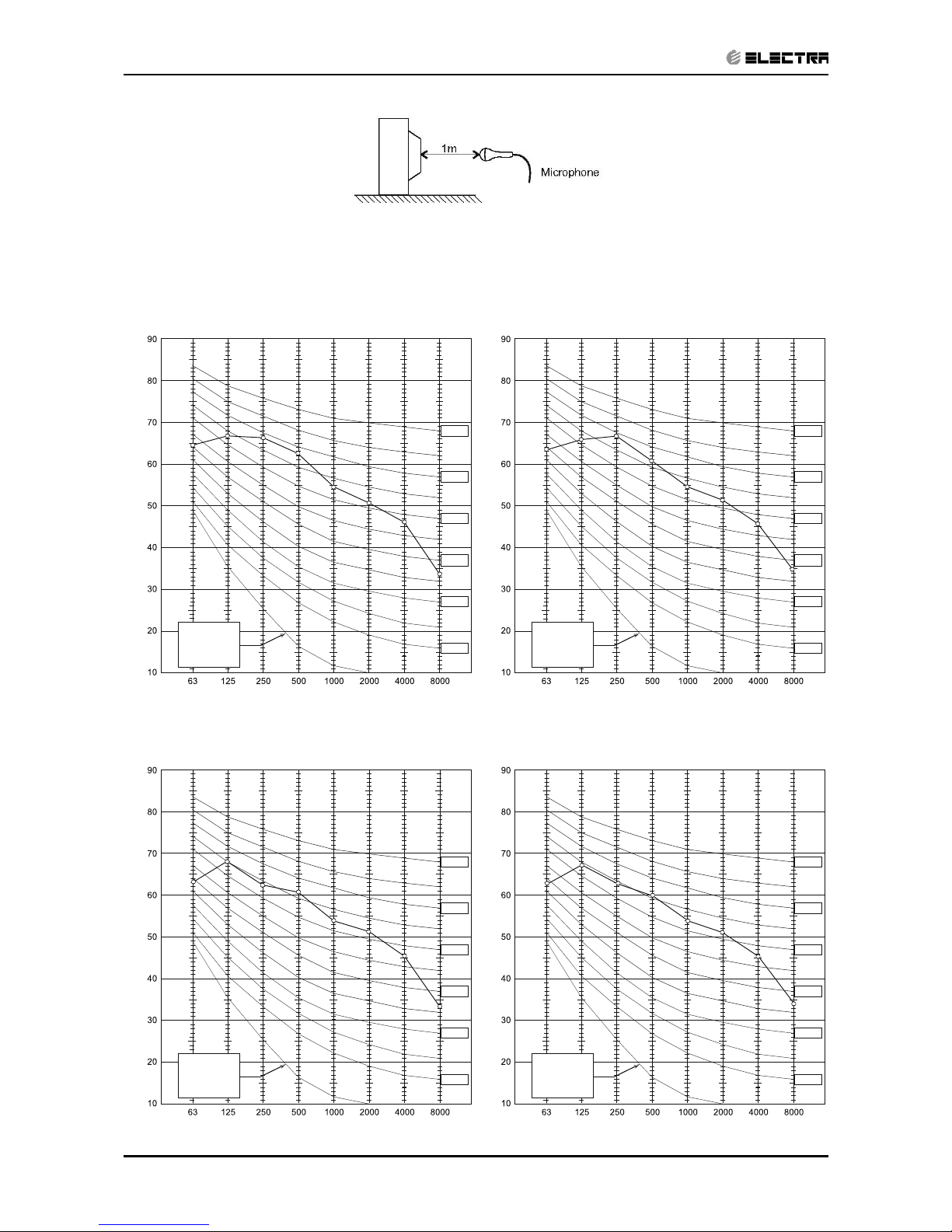
6.3 Sound Pressure Level Spectrum (Measured as Figure 2)
SP 11 Cooling SP 11 Heating
BAND CENTER FREQUENCIES, Hz
APPROXIMATE
THRESHOLD OF
HEARING FOR
CONTINUOUS
NOISE
NC-70
NC-60
NC-50
NC-40
NC-30
NC-20
OCTAVE BAND SOUND PRESSURE LEVEL, dB re 0.002 MICRO BAR
SP 16 Cooling
SP 16 Heating
Fig.2 Microphone Distance from Unit
BAND CENTER FREQUENCIES, Hz
APPROXIMATE
THRESHOLD OF
HEARING FOR
CONTINUOUS
NOISE
NC-70
NC-60
NC-50
NC-40
NC-30
NC-20
OCTAVE BANDSOUNDPRESSURE LEVEL, dB re 0.002 MICRO BAR
BAND CENTER FREQUENCIES, Hz
APPROXIMATE
THRESHOLD OF
HEARING FOR
CONTINUOUS
NOISE
NC-70
NC-60
NC-50
NC-40
NC-30
NC-20
OCTAVE BAND SOUND PRESSURE LEVEL, dB re 0.002 MICRO BAR
BAND CENTER FREQUENCIES, Hz
APPROXIMATE
THRESHOLD OF
HEARING FOR
CONTINUOUS
NOISE
NC-70
NC-60
NC-50
NC-40
NC-30
NC-20
OCTAVE BAND SOUND PRESSURE LEVEL, dB re 0.002 MICRO BAR
Page 23
7-1
ELECTRICAL DATA
Revision Y05-01Service Manual - MOBILE Series
7. ELECTRICAL DATA
7.1 Single Phase Units
MODEL Monoblock 7 SP 11 SP 16
Power Supply
To indoor To indoor To indoor
1PH-230V-50Hz 1PH-230V-50Hz 1PH-230V-50Hz
Max Current, A 5.4 6.2 11
Circuit Breaker,A 10 10 15
Power Supply Wiring
(No. X Cross Section, mm2 )
3x1.0 mm
2
3x1.0 mm
2
3x1.5 mm
2
*Interconnecting Cable RC
Model (No. X Cross Section, mm2)
N/A
4x1.0 mm2 +2x0.5 mm
2
(OCT sensor)
4x1.0 mm2 +2x0.5 mm
2
(OCT sensor)
*Interconnecting Cable ST
Model (No. X Cross Section, mm2)
N/A 4x1.0 mm
2
4x1.0 mm
2
*Already connected on factory as standard
NOTE
Power wiring cord should comply with local lows and electrical
regulations requirements.
Page 24
8-1
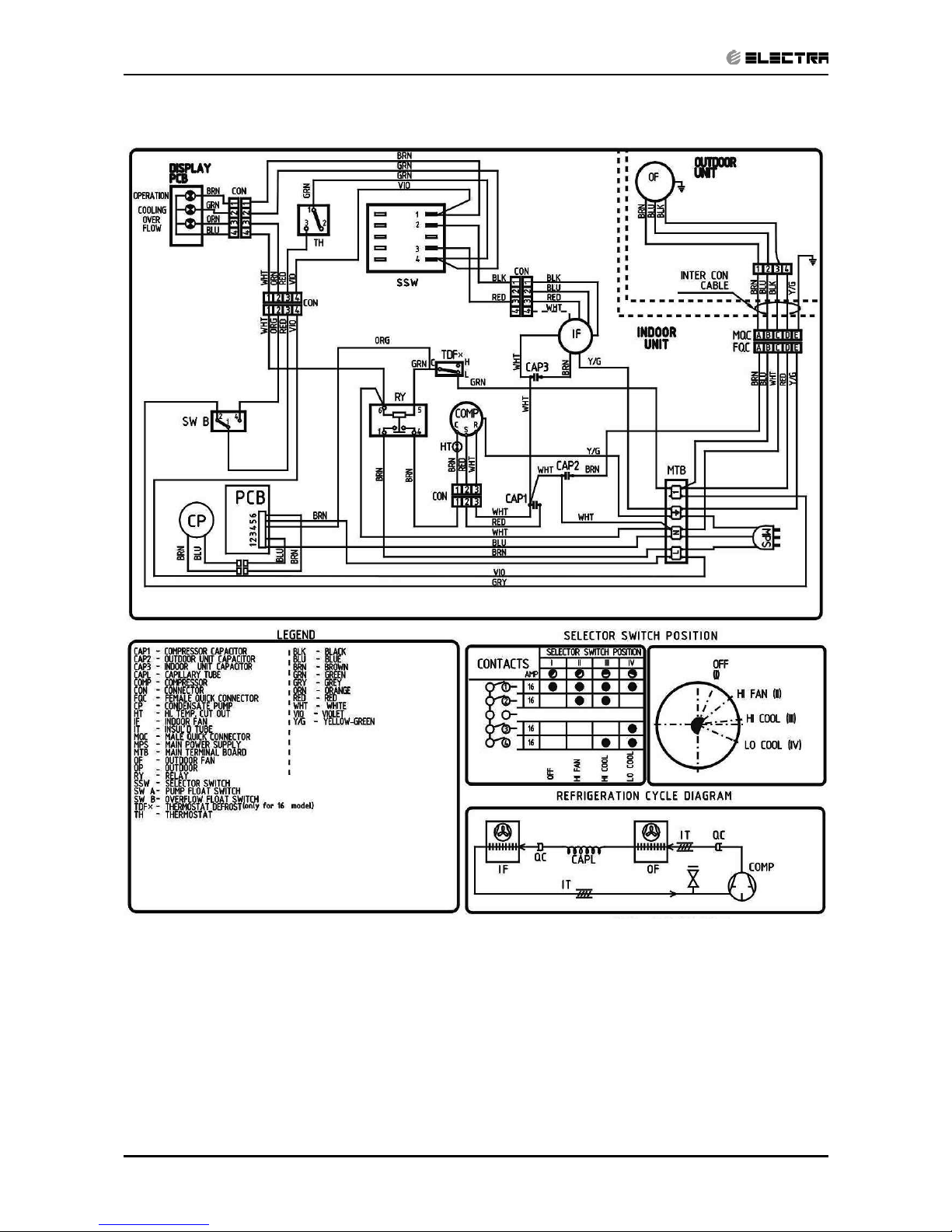
WIRING DIAGRAMS
Revision Y05-01Service Manual - MOBILE Series
8. WIRING DIAGRAMS
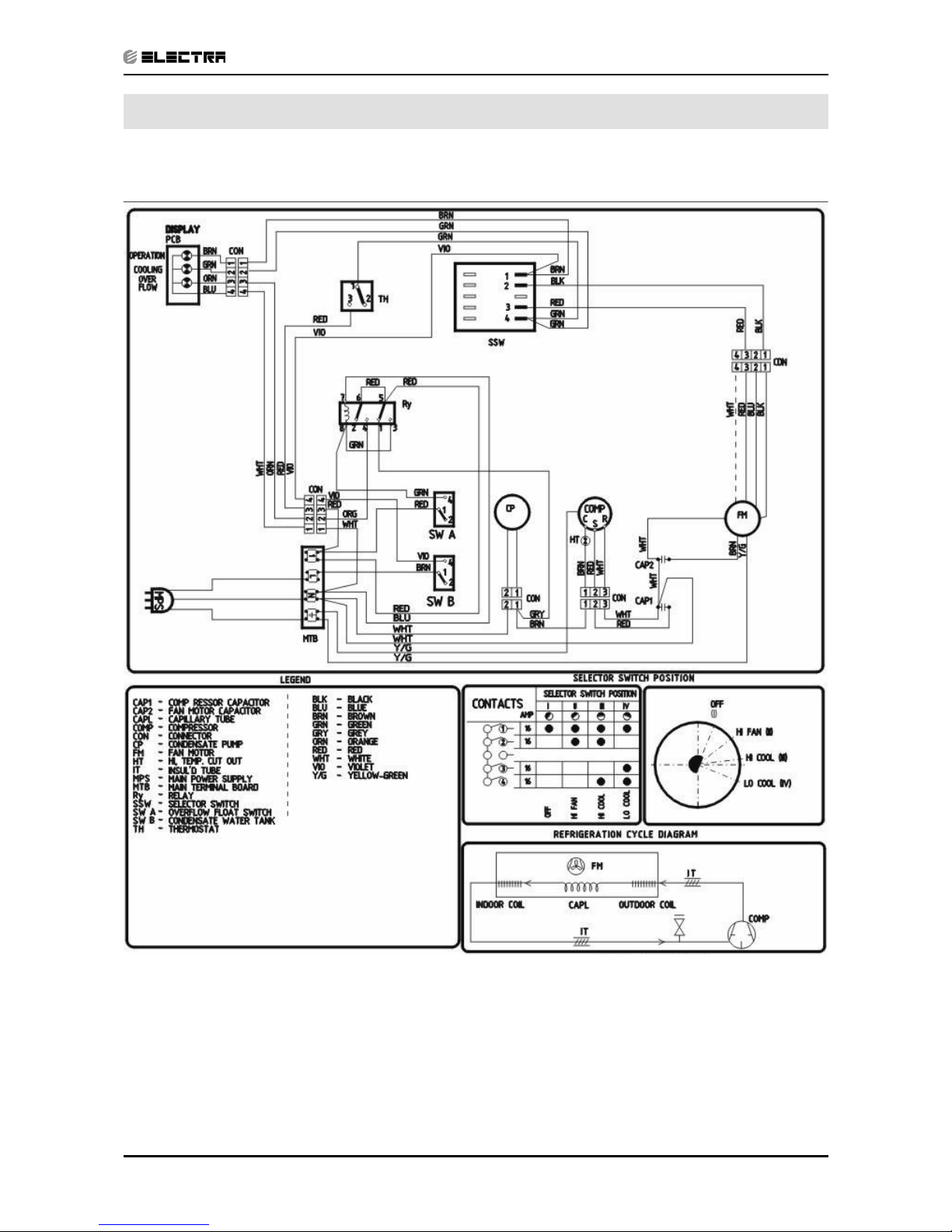
8.1 Monoblock 7 (Mechanical Model)
Page 25
8-2
WIRING DIAGRAMS
Revision Y05-01 Service Manual - MOBILE Series
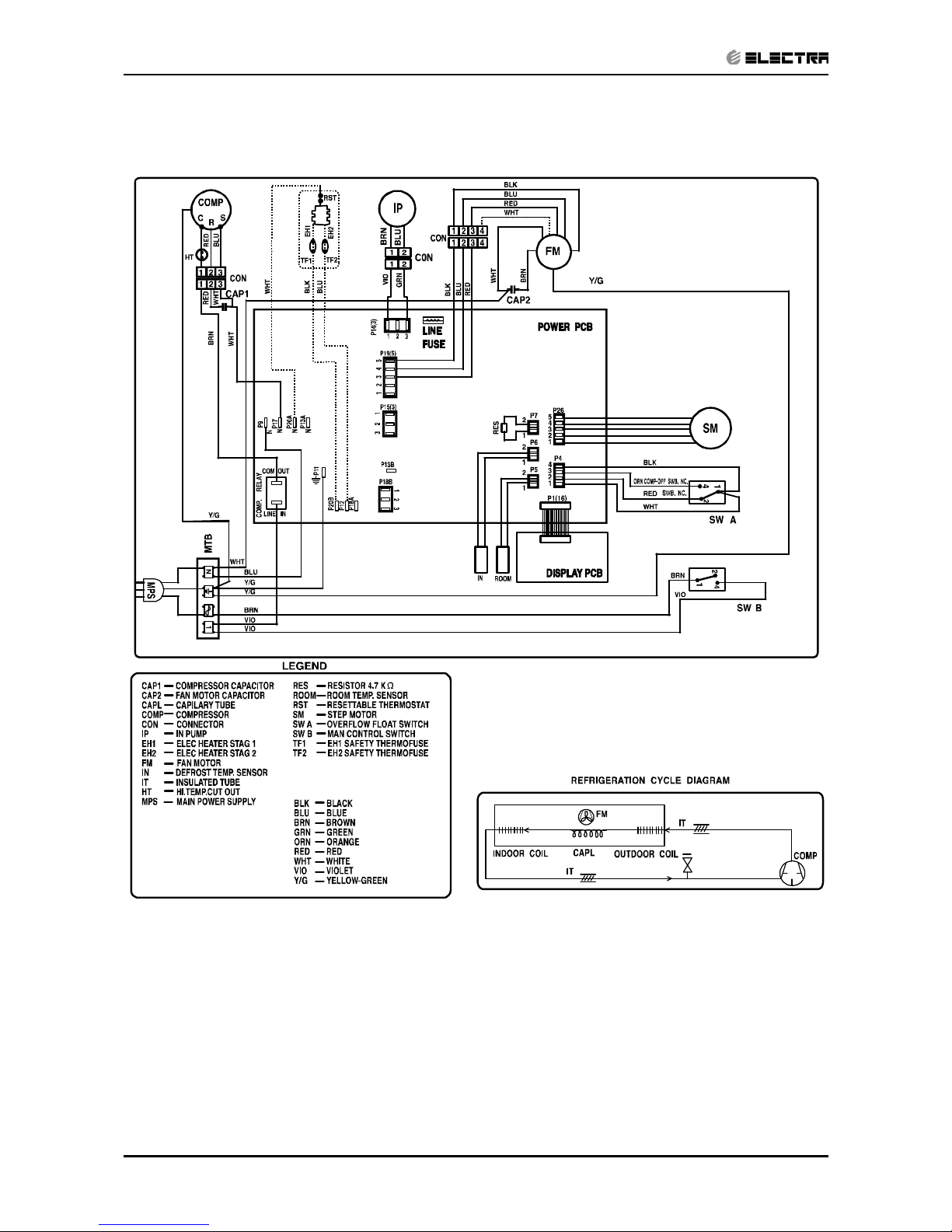
8.2 Monoblock 7 (Electronic Model)
Page 26
8-3
WIRING DIAGRAMS
Revision Y05-01Service Manual - MOBILE Series
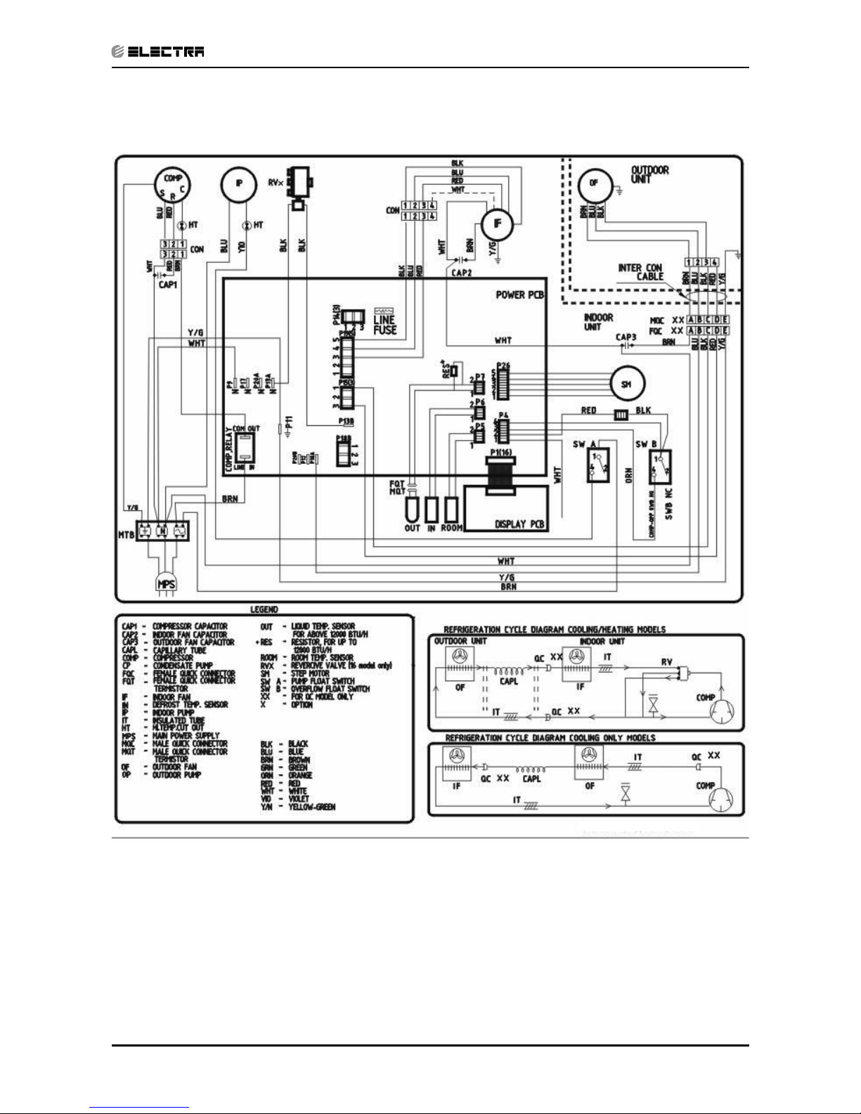
8.3 SP 11/16 (Electronic Model)
Page 27
8-4
WIRING DIAGRAMS
Revision Y05-01 Service Manual - MOBILE Series
8.4 SP 11/16 (Mechanical Model)
Page 28
9-1
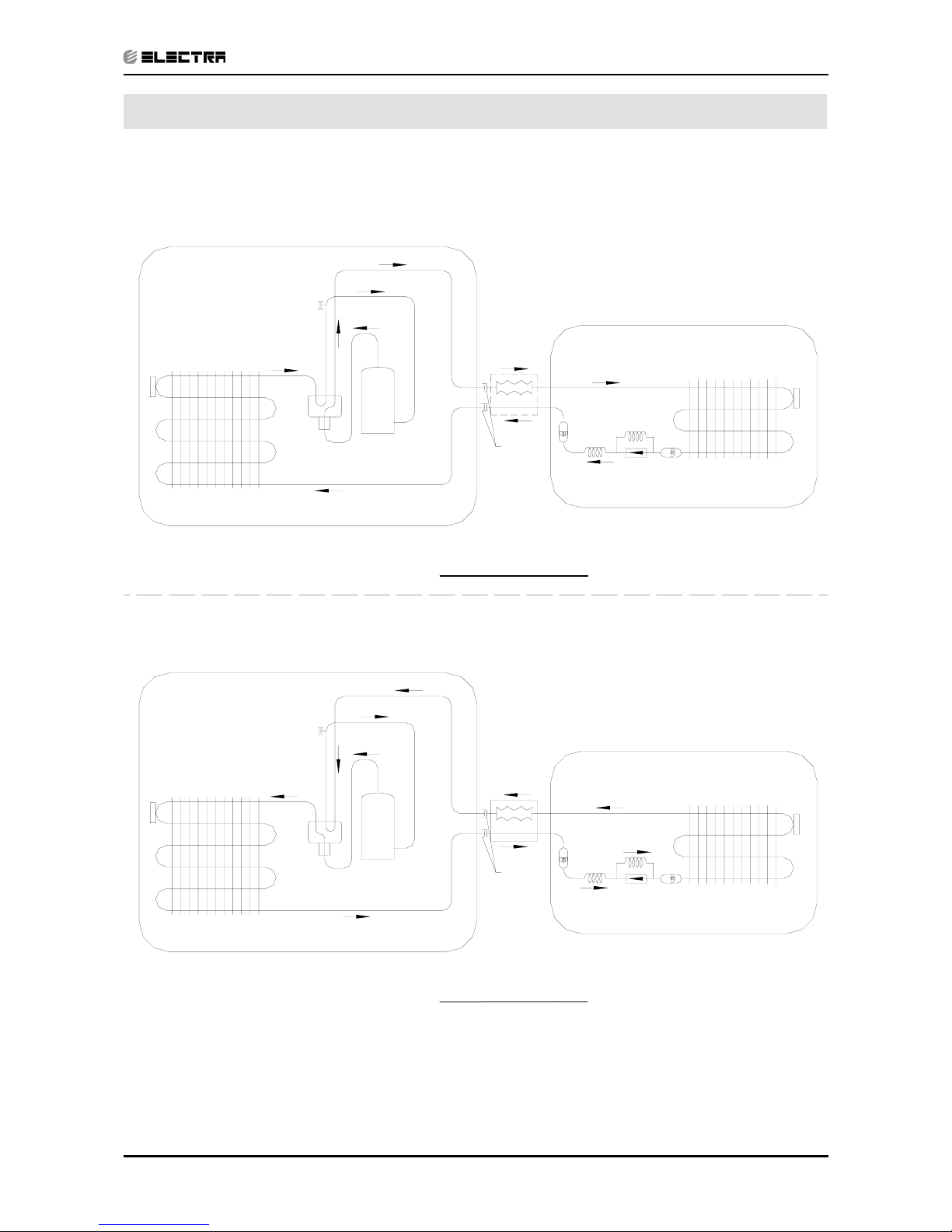
REFRIGERATION DIAGRAMS
Revision Y05-01Service Manual - MOBILE Series
9. REFRIGERATION DIAGRAMS
9.1 Heat Pump Models
9.1.1 SP11, 16 RC
HEATING MODE
Flexible
Tube
Quick
Connector
COOLING MODE
Flexible
Tube
Quick
Connector
INDOOR UNIT
Sensor
Indoor coil
valve
Reverse
Compressor
port
Service
*
INDOOR UNIT
Sensor
Indoor coil
valve
Reverse
Compressor
port
Service
*
Sensor
*
Opt i onal
*
Opt i onal
OUTDOOR UNIT
tube
Capillary
Filter
tube
Single
Valve
Capillary
Outdoor coil
Filter
Sensor
OUTDOOR UNIT
tube
Capillary
Filter
Single
Valve
Capillary
tube
Outdoor coil
Filter
*Optional
*Optional
Page 29
9-2
REFRIGERATION DIAGRAMS
Revision Y05-01 Service Manual - MOBILE Series
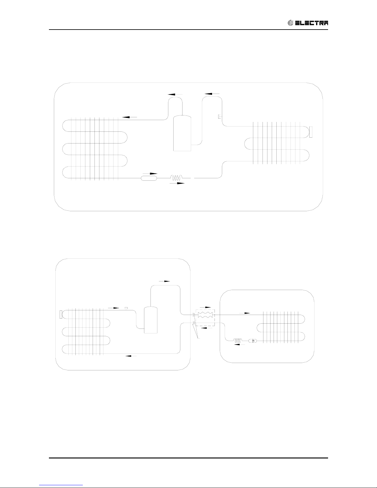
9.2 Cooling Only Models
9.2.1 Monoblock 7 ST
10.2.2 SP 11, 16 ST
Capillary
tube
Condenser
Filter
Evaporator
Compressor
port
Service
Sensor
Indoor coil
Sensor
Service
port
Compressor
INDOOR UNIT
* Opt i onal
Filter
OUTDOOR UNIT
Quick
Connector
Flexible
Tube
*
Capillary
tube
Outdoor coil
*Optional
Page 30

10-1
CONTROL SYSTEM
Revision Y05-01Service Manual - MOBILE Series
10. CONTROL SYSTEM
10.1 Electronic Control
10.1.1 Introduction
The electronic control information is designed for service applications, and is common
to the following groups of air-conditioners:
• ST/ RC group -Cooling only / cooling and heating by heat pump.
• SH group -Cooling and heating by heat pump and supplementary
heater.
• RH group -Cooling, heating by heaters only.
10.1.2 Jumpers Settings
GROUP J6 Setting J2 Setting
ST / RC Open Open
SH Closed Open
RH Closed Closed
Model Plug
Page 31

10-2
CONTROL SYSTEM
Revision Y05-01 Service Manual - MOBILE Series
10.2 Legend
AC - Alternate Current
A/C - Air-Conditioner
ANY - ON or OFF status
CLOCK - ON/OFF Operation Input, (dry contact)
COMP - Compressor
CPU - Central Processing Unit
ELUM - Extended Louver Upward Movement (Software Jumper)
E²PROM, EEP - Erase Enable Programmable Read Only Memory
HE - Heating Element
HPC - High Pressure Control
H/W - Hardware
ICP - Indoor Condensation Pump
ICT - Indoor Coil Temperature (RT2) sensor
IF, IFAN - Indoor Fan
IR - Infra Red
LEVEL1 - Normal Water Level
LEVEL2/3 - Medium/High Water Level
LEVEL4 - Overflow Level
Max - Maximum
Min - Minimum
min - Minute (time)
NA - Not Applicable
OCP - Outdoor Condensation Pump
OCT - Outdoor Coil Temperature (RT3) sensor
OF, OFAN - Outdoor Fan
OPER - Operate
Para. - Paragraph
RAT - Return Air Temperature (RT1) sensor
RC - Reverse Cycle (Heat Pump)
R/C - Remote Control
RCT - Remote Control Temperature
RH - Resistance Heater
RT - Room Temperature (i.e. RCT in IFEEL mode, RAT otherwise)
RV - Reversing Valve
SB, STBY - Stand-By
sec - Second (time)
Sect - Section
SH - Supplementary Heater
SPT - Set Point Temperature
ST - Standard (a Model with Cooling Only)
S/W - Software
TEMP - Temperature
W/O - Without
WVL - Water Valve
∆T - The difference between SPT and RT.
in Heat Mode: ∆T = SPT-RT
in Cool/Dry/Fan Mode: ∆T = RT-SPT
Page 32

10-3
CONTROL SYSTEM
Revision Y05-01Service Manual - MOBILE Series
10.3 Main PCB Controller
Page 33

10-4
CONTROL SYSTEM
Revision Y05-01 Service Manual - MOBILE Series
10.4 General functions
10.4.1 COMP operation
For each Mode including POWER OFF & SB, a Min time delay of 3 min
before COMP restarting, excluding DEICING Mode
The Min operation time of COMP under different operating conditions is
Operation Mode
Min operation time of
COMP
Heat, Cool or Auto Modes 3 min.
Fan, Dry, Overflow, Protection modes, or mode change ignored
10.4.2 IFAN operation
• Min time interval between IFAN speed change in AUTOFAN Mode, is 30 sec.
• Min time interval between IFAN speed change in H/M/L Mode is 1 sec.
• IFAN speed in Heat/Cool Autofan Mode is determined according to the following table:
∆T IFAN Speed
∆T ≥ 2 HIGH
2 ≥ ∆T ≥ 1 MED
1 ≥ ∆T LOW
where in Heat Mode: ∆T = SPT-RT
in Cool Mode: ∆T = RT-SPT
Note:
• In Heat Mode, the rules in section 4.0.3 have the higher priority.
• The table above can be represent by a hysteresis curve which
will minimize the switching of the IFAN relay and will minimize the
change in IFAN speed:
T [oc]
L
M
H
IFAN speed
321
10.4.3 OFAN operation
• Min time interval between OFAN ON/OFF state change is 30 sec.
• In general, OFAN starts together with COMP.
10.4.4 HE operation
• Minimum Heaters ON or OFF time is 30 sec.
• Heaters can be activated only if IFAN is on.
Page 34

10-5
CONTROL SYSTEM
Revision Y05-01Service Manual - MOBILE Series
10.4.5 Protections
• High pressure protection is applicable to all operating modes.
• Deicing control is valid in Heat and Auto Heat Mode only.
• Defrosting control is valid in Dry, Cool, Heat and Auto Modes.
• No reset after protection modes.
10.4.6 Thermistors operation
• Return air Temp. is detected by RAT (RT1) in normal Mode, or by RCT (R/C sensor)
in I-FEEL Mode.
• Indoor Coil Temp. is detected by ICT (RT2).
10.4.6.1 Definition of thermistor faults:
a. Thermistor is disconnected The thermistor reading is below -30
o
c.
b. Thermistor is shorted The thermistor reading is over 75
o
c.
c. Thermistor Temp reading doesn’t change (irrelevant for RT1) -
(i) This test is performed only once after a unit is switched from
OFF/STBY to operation. At the first occurrence of 10 min
continuous COMP operation, the current ICT & OCT are
compared with those when the COMP was switched from OFF
to ON 10 min before. If the ∆T is less than 3
o
c, the thermistor is
regarded as defective.
(ii) The ICT and OCT no-change error can be disabled together by
connecting a4.7 kohm resistor (5%) to the OCT connector. These
resistors are equivalent to a thermistor at 43+/-1
o
c and 48+/-1oc
respectively.
(iii) Connecting a 4.7k resistor to the ICT connector will disable the
ICT no-change error only.
Page 35

10-6
CONTROL SYSTEM
Revision Y05-01 Service Manual - MOBILE Series
10.4.6.2 Cases for disabling thermistor short/disconnected detection
i. The detection of thermistor faults (a) and (b) above, are disabled when Deicer
Protection is started. The detection will be enabled again only after (1) the
deicing is completed, and (2) COMP has been restarted and operated for 30
sec.
ii. When all the following conditions are fulfilled:
a. 4.7K Ohm resistor is connected on the OCT
b. IFAN is OFF
c. Compressor is ON
d. ICT < -30 (disconnected)
This condition come to detect and prevent IFAN operation in Deicer in multi spilt
units.
10.4.6.3 Handling the thermistor faults in a COMP unit
i. ICT/OCT thermistor is disconnected or shorted -
The invalid thermistor temperature is replaced by 43oc, so that the unit
can continue the normal operation. All protections related to that faulty
thermistor will be disabled. For example, in case of any ICT fault, the ICT
high pressure protection in Heat Mode and ICT defrost protection in Cool
Mode will not operate anymore. The same is also applied to the OCT fault.
ii. RAT thermistor is disconnected or shorted –
The RAT will be derived from the ICT by using the equations :
Heat Mode: RAT=ICT/2.3
Cool Mode RAT=ICT*4
Notes:
• In case of any thermistor failure, the STBY LED will be blinking until the
fault condition is corrected.
• User can use the system diagnostics function to find out the nature of
the thermistor faults.
i. RAT thermistor is disconnected or shorted –
System will operate continuously in the last IFAN & WVL status when
turned ON.
Notes:
• As in the COMP unit, the STBY LED will be blinking to indicate a
thermistor fault. And, the user can use the system diagnostics function
to find out the nature of the fault.
Page 36

10-7
CONTROL SYSTEM
Revision Y05-01Service Manual - MOBILE Series
10.5 Cooling Mode - General
1) Room Temperature, RT, is detected by
• RAT in normal operation, or
• RCT (R/C sensor) in I-FEEL mode.
2) The resolution of RT is 1oc.
• RT is activating COMP/WVL if (RT > SPT), and
• RT is stopping COMP/WVL if (RT =< SPT).
3) Indoor Coil Temp is detected by ICT (RT2).
4) Outdoor Coil Temp is detected by OCT (RT3).
5) A WVL-RC/SH will work in Cooling Mode when
• ICT < 16
o
c in general (see Sect 2.2.2 for details), and
• Unit is not operating in Fan Mode.
6) OFAN OPERATIONS
• OFAN starts together with COMP in general.
Page 37

10-8
CONTROL SYSTEM
Revision Y05-01 Service Manual - MOBILE Series
10.5.1 Cooling
Mode: Cool, Auto (at Cooling)
Temp: Selected desired temperature.
Fan: HIGH, MED, LOW
Timer: Any
I Feel: On or Off
Control function
Maintains room temp at desired level by comparing RT and SPT.
(RT - SPT) [oc]
+3
+2
+1
0
-1
-2
ON
OFF
ON
OFF
USER FAN SPEED
ON
OFF
COMP
(WVL)
OFAN
IFAN
RV
Note:
1) IFAN is always running at High, Medium or Low speed selected by user.
2) In IFEEL mode, the Room Temperature (RT) is the RCT from a R/C. Otherwise, the
RT is the RAT from the Room Thermistor.
Page 38

10-9
CONTROL SYSTEM
Revision Y05-01Service Manual - MOBILE Series
10.5.2 Cooling with Autofan
Mode: Cool, Auto (at cooling)
Temp: Selected desired temperature
Fan: Auto
Timer: Any
I Feel: On or Off
Control function
Maintains room temp at desired level and controls the IFAN speed for optimal comfort.
(RT - SPT) [oc]
+3
+2
+1
0
-1
-2
ON
OFF
ON
OFF
H
L
M
ON
OFF
COMP
(WVL)
OFAN
IFAN
RV
Page 39

10-10
CONTROL SYSTEM
Revision Y05-01 Service Manual - MOBILE Series
10.6 Heating Mode
10.6.1 Heating Mode - General
• In heating Mode, temp. compensation schedule will be activated for wall mounted
units.
SPT [oc]
Add to SPT
I-FEEL ON I-FEEL OFF
18 ≤ SPT ≤ 27 0
o
c+2
o
c
27 < SPT ≤ 30 0
o
c+3
o
c
Notes :
• No compensation will be activated in Forced operation modes
10.6.2 IF operating rules
• As a general rule for RC and SH groups, when COMP is ON, excluding
protection modes, IFAN will be switched ON if
• ICT > 35oc or
at the IFTC 30 sec after the COMP is switched ON. In
this case, the IFAN will be started at low speed.
Notes :
1) In SH or RC group, if HE is set to OFF due to low ICT, IFAN will be
switched to LOW and will be turned OFF after 30 sec.
2) An exception to this rule (4.0.3.a) is the Back-up mode for SH.
• In RC and SH groups, whenever COMP & HE are both
OFF, excluding protection modes, IFAN operation will be according
to the following:
In other models IFAN will operate in low speed for 30 sec and then stop. If
COMP is OFF for more than 3 minutes and IFEEL Mode is inactive, IFAN will
operate in low speed according to the following graph:
IFAN Speed
Any
Low
Stop
30 35 40
EMD/ELD
EMD/ELD
ICT [oc]
15 20 25
General :
For WAX :
SPT+4 SPT+6 ICT
[
o
c
]
ON
OFF
IFAN (Low Speed)
Page 40

10-11
CONTROL SYSTEM
Revision Y05-01Service Manual - MOBILE Series
10.6.3 HE operation
• For all Groups, HE can be ON only when IFAN is ON.
• For all Groups, HE switches to OFF when ICT > 50
o
c, and is activated
again when ICT ≤ 45oc.
• In SH or RC group, HE operation is limited by the following graph:
• Back-up mode for SH group
After COMP has been working for 5 minutes, HE & IFAN are activated even
if the ICT is still below 35
o
c. This situation is called Back-up Mode. Both
HE & IFAN will work in Back-up Mode until the ICT reaches 35oc. Then, the
operation goes on in the usual mode .
HE
ON
OFF
30
45 50
ICT [oc]
15
General :
For WAX :
35
20
40
Page 41

10-12
CONTROL SYSTEM
Revision Y05-01 Service Manual - MOBILE Series
10.6.4 Heating, RC or SH Group
Mode: Heat, Auto (at heating)
Temp: Selected desired temperature
Fan: HIGH, MED, LOW
Timer: Any
I Feel: On or Off
Control function
Maintains room temp. at desired level by comparing RAT or RCT to SPT.
(RT - SPT) [oc]
+2
+1
0
-1
-2
-3
ON
OFF
ON
OFF
H/M/L
OFF
L
ON
OFF
Note 1 Note 2
COMP
(WVL)
HE1
HE2
IFAN
ON
OFF
RV
Page 42

10-13
CONTROL SYSTEM
Revision Y05-01Service Manual - MOBILE Series
10.6.5 Heating, RC or SH Group with Autofan
Mode: Heat, Auto (at heating)
Temp: Selected desired temperature
Fan: Auto
Timer: Any
I Feel: On or Off
Control function
Maintains room temp at desired level by controlling COMP, IFAN and OFAN.
(RT - SPT) [oc]
+2
+1
0
-1
-2
-3
ON
OFF
ON
OFF
H
OFF
L
M
ON
OFF
Note 1 Note 2
COMP
(WVL)
HE1
HE2
IFAN
RV
ON
OFF
Page 43

10-14
CONTROL SYSTEM
Revision Y05-01 Service Manual - MOBILE Series
10.6..6 OFAN operation is controlled by the graph below when
1. (RAT ≥ SPT – 2oc), AND
2. (ICT ≥ 45
o
c), AND
3. (COMP is ON)
Otherwise, OFAN runs together with COMP.
OCT [oc]
+3
+2
+1
0
-1
OFAN
ON
OFF
Page 44

10-15
CONTROL SYSTEM
Revision Y05-01Service Manual - MOBILE Series
10.7 Automatic Cooling or Heating
10.7.1 Automatic Cooling or Heating - General
• Switching-temperature between Cooling and Heating is SPT ± 3oc.
• Autofan in Automatic Cooling and Heating Mode will activate “Cooling
with Autofan Mode” and “Heating with Autofan Mode” respectively.
• When the Auto Mode is started with SPT +/-0
o
c, the unit will not select
Auto Heat or Auto Cool mode immediately. Instead, the unit will be in
a temporary Fan Mode with IFAN operating at low speed.
The proper Auto Heat mode or Auto Cool will be started whenever the RT
reaches SPT-1oc or SPT+1oc respectively.
• For RC & SH units, Mode change between Auto Heat & Auto Cool
Modes is possible only after the COMP has been OFF during the
last T minutes.
Mode Change time, T
Auto Cool to Auto Heat 3 min
Auto Heat to Auto Cool 4 min
• When unit is changed form Cool/Dry mode to Auto Mode, the unit
will continue to operate at (Auto) Cool Mode until the conditions for
switching from Auto Cool to Auto Heat are satisfied.
Similarly, when unit is changed from Heat Mode to Auto Mode, the
unit will continue to operate at (Auto) Heat Mode until the conditions
for switching from Auto Heat to Auto Cool are satisfied.
Page 45

10-16
CONTROL SYSTEM
Revision Y05-01 Service Manual - MOBILE Series
10.7.2 Auto Cooling or Heating, RC or SH Groups
Mode: Auto
Temp: Selected desired temperature
Fan: Any
Timer: Any
I Feel: On or Off
Control function
Maintains room temp at desired level by selecting between cooling and heating modes.
(RT - SPT) [oc]
+3
+2
+1
0
-1
-2
-3
ON
OFF
ON
OFF
H/M/L/OFF
L/OFF
ON
OFF
ON
OFF
COMP
& OFAN
HE1
HE2
IFAN
RV
H/M/L/OFF
L/OFF
USER FAN SPEED H/M/L/OFF
L/OFF
Auto Cool Mode Auto Heat Mode
> 4 min > 3 min
> 3 min > 2 min
(3) (3)
(4)
(4)
(5)
Auto Heat Mode
Page 46

10-17
CONTROL SYSTEM
Revision Y05-01Service Manual - MOBILE Series
10.8 Dry Mode
10.8.1 Dry, ST or RC group
Mode: Dry
Temp: Selected desired temp
Fan: Low (automatically selected by software)
Timer: Any
I FEEL: Any
Control function
Reduce room humidity with minimum temp. fluctuations by operating in Cool Mode with
low speed IFAN.
Notes :
• When Dry is ON, the COMP is forced OFF for 3.5 min (longer than the
3 min Min COMP-Off time) after every 15 min of continuous COMP
operation.
• When Dry is OFF, the COMP is forced ON for 6 min (longer than the 3
min Min COMP-On time) after every 15 min of continuous COMP OFF
time.
• When Dry is changed from ON to OFF or vice versa, the limits
mentioned in (1) & (2) are ignored. The COMP operation is only
controlled by the 3 min Min OFF time and 1 min Min ON time.
• In Dry Mode, IFAN is LOW when COMP is ON, and is OFF when
COMP is OFF.
DRY
(RT - SPT) [oc]
+2
+1
0
-1
-2
ON
OFF
ON
OFF
LOW
OFF
DRY-ON
DRY-OFF
ON
OFF
Time [min]
10
20
30
40 50
Max 15 minutes
3.5
min
Note1
6 min
Note 2
COMP
& OFAN
HE1
& HE2
IFAN
RV
Max 15 minutes
5 minutes COMP
ON time
Page 47

10-18
CONTROL SYSTEM
Revision Y05-01 Service Manual - MOBILE Series
10.9 Protection
10.9.1 Cooling Mode Protections
Indoor Coil Defrost
Mode: Cooling, Dry, Auto
Temp: Selected desired temp.
Fan: Any
Timer: Any
I Feel: On or Off
Control Function
Protect the indoor coil from ice formation at low ambient temperature.
t1 = 5 min minimum for each COMP starting
t2 = OFAN cycling (alternate between ON and OFF every 30 sec) for 20 min
maximum
t3 = COMP and OFAN stop for 10 min minimum
Notes:
• When J7 is closed (connected), OFAN cycling is cancelled and the
set temperature for COMP & OFAN cut-out and cut-in are changed.
COMP & OFAN are forced OFF when ICT =< -6oc, and are kept OFF
until ICT > 14oc.
• For WAX model, the defrost processes is simpler. When J7 is open,
COMP & OFAN are forced OFF when ICT =< -1oc, and are kept OFF
until ICT > 5oc. When J7 is closed, the WAX defrosting process is the
same as that of the other models (R.H.S. of the graph above). In both
cases, the ICT checking in t2 and t3 are not applied.
ICT [oc]
+2
ON
OFF
ON
OFF
t1 t2 t3
COMP
OFAN
+1
+5
+14
0
-1
-6
ON
OFF
IFAN
J7 OPEN J7 CLOSED
t1 t1
Page 48

10-19
CONTROL SYSTEM
Revision Y05-01Service Manual - MOBILE Series
10.9.2 High Pressure Protection
Mode: (Auto) Cooling or Dry
Temp: Selected desired temp.
Fan: Any
Timer: Any
I Feel: On or Off
Control Function
To protect the COMP from the high pressure built-up in the outdoor coil during normal
cooling operation, by switching OFF the IFAN and COMP.
OCT [oc]
Any
OFF
Any
ON
Any
Blink
ON
COMP
OFAN
IFAN
OPER
LED
52
55
61
66
L
COMP is forced OFF
OFAN is forced ON
IFAN forced
to LOW
68
OFAN follow operation of
COMP
COMP is forced OFF
OFAN is forced ON
For all models except WAX & P2000 For WAX & P2000 models
Note:
• The ICT is also monitored during Cool and Dry mode, in case the RV control circuit
is faulty. Whenever ICT reaches 70oc, which indicates a high pressure in the indoor
coil, the COMP will be forced off automatically. The COMP can be turned on again only
after the ICT is under 70oc again and after the 3 min COMP ON delay time. The OPER
LED will not blink in this case.
Page 49

10-20
CONTROL SYSTEM
Revision Y05-01 Service Manual - MOBILE Series
10.9.3 Heating Mode Protections
Outdoor coil Deicing (excluding RH Group)
Mode: Heating, Auto (at heating)
Temp: Selected desired Temp
Fan: Any
Timer: Any
I FEEL: Any
Control function
Protects the Outdoor coil from ice formation by controlling COMP & RV operation.
Scope
This new deicer is designed to operate at extreme temp conditions. The deicing cycle
could be triggered from:
1. OCT temp and time between two consecutive deicing cycles.
2. Detection of ice forming by change of the OCT temp.
Both algorithms adjust the time between deicing cycles to optimize the A/C
performance. The algorithm will automatically increase the time between deicing cycles
and reduce the deicing cycle as needed.
The algorithm uses EEPROM data to operate.
Page 50

10-21
CONTROL SYSTEM
Revision Y05-01Service Manual - MOBILE Series
Deicing procedure
OCT [oc]
ON
OFF
ON
OFF
ON
L
ANY
COMP
OFAN
RV
IFAN
DST
(DDT)
0
12
OFF
HEs are forced ON
DOC
ANY
ON
HE
36s 36s
DT
30s
max 12 min.
Note 3
DI (note 1)
DI (note 2)
30s
3 min 3 min
IFAN
OFF
ANY
HE
OFF
ANY
all SH units
except WAX
RC or WAX units
HEs are forced OFF
IFAN is forced to Low Speed
BLINK
ON
OPER
LED
Notes :
• At the first COMP activation after SB or OFF, if (OCT < 0oc), then DI = 10
min, else DI = 40 min.
• In the following Deicing cycles, the time interval between two Deicing
cycles activation is between 30 to 80 min (refer to the flow chart).
• For RC group, HEs are forced OFF. IFAN operation is as in Heat
Mode, Sect 4.0.3.a, i.e. IFAN will be set to OFF when ICT<30
o
c.
For WAX, the IFAN is simply forced OFF.
• For SH group, HEs are forced ON and IFAN is forced to operate in Low
speed, regardless of the ICT and difference between RAT & SPT.
Page 51

10-22
CONTROL SYSTEM
Revision Y05-01 Service Manual - MOBILE Series
10.9.4 High pressure protection (excluding RH Group)
Mode: (Auto) Heating
Fan: Any
Timer: Any
I Feel: On or Off
Control Function
Protect the Compressor from high pressure by switching OFF the OFAN and COMP.
ICT [oc]
Any
Off
Any
Off
COMP
OFAN
52
55
61
66
COMP is forced OFF
67
OFAN is force
Off
COMP is forced OFF
For all models except WAX For WAX model
ON
BLINK
OPER
LED
Notes:
• IFAN, HE1 and HE2 will be activated according to the relevant
Heating Mode Sect.
• In case of any malfunction in the relay control circuit, the OCT is also
monitored during heating mode. Whenever OCT reaches 70
o
c, which indicates
a high pressure in the outdoor coil, the COMP will be forced off automatically.
The COMP can be turned on again only after the 3 min COMP ON delay and the
OCT is under 70oc. The OPER LED will not blink in this case.
Page 52

10-23
CONTROL SYSTEM
Revision Y05-01Service Manual - MOBILE Series
10.9.5 Indoor Condensation Pump (ICP) Operation and Overflow
Protection (PXD, P2000 and MBX Models)
Mode: Cooling, Dry, Auto (at Cooling)
Temp: Desired temp selected
Fan: Any
Timer: Any
I Feel: On or Off
Control function:
To prevent the overflow of condensed water by turning ON the ICP.
Notes:
• When water level reaches LEVEL 4, ICP will be turned ON even if the unit is
in SB mode.
• Under normal operation, at least one of the water level inputs must be active.
If all LEVEL1, LEVEL2&3 and LEVEL4 are inactive, it is assumed that the
connection has been broken and the ICP will be turned ON when the unit is
operating in Cool or Dry mode.
• The operation of the pump is not related to the ON/OFF state of the COMP.
On the contrary, the COMP can be forced to OFF when the water level is high
(level 4).
• The water level inputs are low active. That is, when a water level is reached,
the voltage at the corresponding input pin of the MCU would be changed from
5V (inactive) to 0V (active).
Water Level
ANY
OFF
BLINK
COMP
& OFAN
FILTER LED
LEVEL1
LEVEL2&3
LEVEL4
NORMAL
ON
ICP
OFF
Page 53

10-24
CONTROL SYSTEM
Revision Y05-01 Service Manual - MOBILE Series
10.9.6 Outdoor condensation pump (P2000 Model)
Mode: Cooling, Auto (at Cooling), Dry.
Temp: Selected Desired temp.
Fan: Any
Timer: Any
Feel: On or Off
Control Function
Pumps condensed water from Indoor unit to Outdoor unit.
Outdoor Condensation Pump Control
The Outdoor pump relay is activated in parallel with the COMP at: Cooling, Dry, and Auto
cooling as described in the following table:
COMP Condensation Pump
ON ON
OFF OFF
Note:
• In Heating Mode, OCP is OFF.
Page 54

10-25
CONTROL SYSTEM
Revision Y05-01Service Manual - MOBILE Series
10.10 Timer
Mode: Any
Temp. Selected desired temp
Fan: Any
Timer: Timer On, Timer Off
I Feel: On or Off
Control function
• Starts or stops the unit operation after pre-set time. If RC-1 is used,
the timer setting will be (0.5 - 24 Hr) from the moment the timer is set.
The minimum resolution is 30 minutes.
If RC-2 or later version of remote controls is used, the timer
setting will be (0:00 - 23:50) real time with 10 minutes resolution.
• After power failure, all pre-set timers are cleared. The system is
forced to STBY mode and the Timer LED indicator is blinked to
indicate the situation. The LED keeps blinking until the timer settings
can be reloaded from a R/C message.
Note: If all timers are inactive, the system will not be forced
OFF after the power failure. The last OPER/STBY status will
be loaded from the EEP instead.
• When the A/C receives any valid message from a R/C, the current
ON/OFF timer settings will be replaced by the new timer settings in
the R/C message.
Note: The following timer related operations will not affect the
A/C operating mode (Heat/Cool/Auto/Dry/Fan) setting.
• Set ON/OFF timer
• Clear ON/OFF timer
• R/C ON Timer is time-up
• R/C OFF Timer is time-up
E.g. When a STBY A/C unit (with Cool Mode setting in its EEP) is
turned on by the ON-TIMER of a R/C with heat mode setting,
the A/C will start in Cool Mode.
Page 55

10-26
CONTROL SYSTEM
Revision Y05-01 Service Manual - MOBILE Series
10.11 Forced Operation
Forced operation allows units to start, stop and operate in Cooling or Heating in pre-set
temperature according to the following table:
Forced operation
mode
Pre-set Temp for ;
MBX, P2000, PRX,
PX, PXD models
Pre-set Temp for :
FCD, RWK, ELD, ECC,
WAX, WMF, WMN, WNG
models
Cooling 20°C22°C
Heating 25°C28°C
Note:
• While under the forced operation, the temperature compensation
schedule.
• The forced operation is activated when the mode button on the
Display Board is used to switch the unit to Cool or Heat mode.
• The IFAN is always set to Autofan Speed in forced operation.
Page 56

10-27
CONTROL SYSTEM
Revision Y05-01Service Manual - MOBILE Series
10.12 Sleep Mode
Mode: Any
Temp: Set – desired temperature selected
Fan: Any
Timer: Interact with Sleep Timer as described in sect 12.2
I Feel: On or Off
The Sleep mode is activated by using the sleep button on the R/C. In Sleep Mode,
the unit will automatically adjust the SPT to turn up/down the room temperature (RT)
gradually to provide maximum comfort to the user in sleep.
Sleep is treated as TIMER function. Therefore, the TIMER LED is activated similar to
TIMER function.
10.12.1 Adjustment in Sleep Mode
1. in cool, auto cool or dry modes, the SPT adjustment is positive (from 0 to +3oc).
2. In heat or auto heat modes, the SPT adjustment is negative (from 0 to -3
o
c).
3. In other modes, there is no SPT adjustment.
4. The SPT adjustment is cancelled when the Sleep mode is cancelled.
Note: If Off-timer is active, the unit may go to SB before or after 7 hours of
sleep operation.
SPT
Time [Hr]
485326
Start
Sleep
7
RT
SPT-1
SPT-2
SPT-3
SPT+2
SPT+1
SPT+3
1
7 Hours Sleep operation
for Normal Sleep Mode
Unit is turned to SB
after Sleep
Cool, Dry modes
Heat mode
Page 57

10-28
CONTROL SYSTEM
Revision Y05-01 Service Manual - MOBILE Series
10.12.2 Time adjustment in Sleep Mode
The user can make use of the Off-Timer to extend the Sleep Time from 7 hours to 12
hour (max). The operation of the new “Extended Sleep Mode” is illustrated by the
graphs below.
Case 1 is the Standard Sleep Mode, which is the only sleep mode in previous version
of MCU. The A/C unit simply works for 7 hours, then goes to SB.
Case 2 is the new Extended Sleep Mode. If an active Off-Timer is set to turn off the
A/C between 7-12 hour, relative to the starting of Sleep, the Sleep time is extended.
And, instead of going to SB at the 7th hour, the A/C will work until reaching the Off-time.
Case 3 is an exception to case 2. The Sleep Mode will not be extended to the Off-Time
when the Off-Timer is preceded by an On-Timer, which is also between 7-12 hour.
Oper
Time [Hr]
48101226
Start
Sleep
7
Case 1 : Standard Sleep Mode
Condition : Off-timer is not set or is beyond 12 hour.
SB
Oper
Time [Hr]
48101226
Start
Sleep
7
Case 2 : Extended Sleep Mode
Condition : Off-timer is set at 7-12 hour.
SB
Off-timer
Oper
Time [Hr]
48101226
Start
Sleep
7
Case 3 : Exception to Case 2
Condition : Off-timer is set at 7-12 hour
On-timer is set at 7-12 hour and before Off-timer
SB
Off-timerOn-timer
Page 58

10-29
CONTROL SYSTEM
Revision Y05-01Service Manual - MOBILE Series
10.13 Clogged Air Filter
Filter LED ON after 512 HR.
Filter LED is turned OFF, and the Filter Timer is restarted by pressing the reset button.
Page 59

10-30
CONTROL SYSTEM
Revision Y05-01 Service Manual - MOBILE Series
10.14 Controller Self-Test Procedure
10.14.1 By Shorting Test Jumper J1
RC/ST TEST
MODEL
CONFIGURATION
TEST
STEP MOTOR TEST
FREQUENCY
TEST
LEDS OFF
LEDS ON TEST
AUTO RELAY
TEST
SHORT JUMPER
J1
(CONTROL PCB)
PRESS ON
POWER
BUTTON
PRESS ON
MODE BUTTON
INDOOR FAN
SPEED TEST
SELF-TEST FLOW CHART
Step 1
Step 2
Step 3
FOR CONTROLLER (VERSION 4V5 OR HIGHER)
COOL
HEAT
COMPRESSOR
OUTDOOR FAN
R.V.
LOW
MEDIUM
HIGH
TIMER
OPERATE
STANDBY
BUZZER TEST
(ONE BEEP SOUND)
REMOTE CONTROL
TO CPU COMUNICATION
(TWO BEEPS SOUNDS)
THERMISTOR ANALOG
VOLTAGE CHECKING
EEPROM MEMORY
TEST
END OF SELF
TEST
PRESS ON RESET
BUTTON
PRESS ON FAN
BUTTON ON THE
REMOTE CONTROL
PRESS ON MODE
BUTTON
PRESS ON MODE
BUTTON
Step 4
Step 5
Step 6
Step 7
Step 8
DISCONNECT
JUMPER
J1
Page 60

10-31
CONTROL SYSTEM
Revision Y05-01Service Manual - MOBILE Series
10.14.2 By Remote Control Settings:
a. 1: TURNING ON THE POWER.
Turn ON the power, make sure that the unit is in operation.
b. STEP 2 : ENABLE SELF-TEST MODE
• Use the remote control to send the first settings to display / indoor unit
HEAT mode, HIGH IFAN, set temperature to 16 ºC, no I-FEEL Sleep or
any other timer settings are needed.
• Cover the IR transmitter components in the remote control so that it will
not transmit the signals to the indoor unit display.
• Use the remote control to send the second settings to display / indoor unit
COOL mode, LOW IFAN, no I-FEEL Sleep or any other timer settings.
• Uncover the remote control IR transmitter and change the temperature
settings. If the display/indoor unit receive the settings properly the
following steps will start:
c. STEP 3: MODEL SETTING CONFIRMATION
• The STAND-BY and COOL LEDS will indicate the operation mode as
follows:
OPERATION MODE STAND-BY LED COOL LED
ST ON OFF
RC OFF OFF
SH OFF ON
RH ON ON
• Testing the Model configuration. Selected by the COMP, STAND-BY,
TIMER LEDS and FILTER will indicate the model configuration as follows
(the relevant line for this manual is highlighted):
MODEL COMP OPERATE LED TIMER LED FILTER LED
WNG ON OFF OFF OFF
WMN1 ON ON OFF ON
WMN4 OFF OFF ON OFF
WMN2/WHX OFF ON OFF ON
WMN3 OFF ON ON ON
P2000 OFF OFF OFF ON
In this term the step motor will turn to HOME POSITION.
Page 61

10-32
CONTROL SYSTEM
Revision Y05-01 Service Manual - MOBILE Series
d. STEP 4 : AUTO LED WALK TEST.
• All the LEDS will turn OFF.
• All the LEDS will turn ON for 1 second one by one in the following
sequence:
STAND-BY OPERATE TIMER FILTER COOL HEAT.
• In PRX all the LEDS will turn ON for 1 second one by one in the following
sequence : 18 °c 20 °c 22 °c 24 °c 26 °c 28 °c 30 °c
High IFAN Auto IFAN Med IFAN Low IFAN STAND-BY
TIMER FILTER COOL HEAT.
e. STEP 5: AUTO REALY WALK TEST:
• All relays will energize one by one in the following sequence:
COMPRESSOR OUTDOOR FANR. V. HEATER 1 HEATER 2
INDOOR WATER PUMP SWING or OUTDOOR WATER PUMP
INDOOR FAN: LOW MID HIGH.
• When the relay walk test is completed, the next test will start
automatically.
f. STEP 6: FREQUENCY TESTING:
• If the frequency measuring process fails the COOL LED will turn ON.
In order to move to the next step, press ON/OFF button on the remote
control.
g. STEP 7: INPUT TEST.
• The test purpose is to check the analog real time indicators (thermistors,
LEVEL and clock) according to the table below.
LED Indicator Condition for LED to be ON
STBY LED Room thermistor ≠ 25°c
OPER LED Indoor coil thermistor ≠ 25°c
TIMER LED Outdoor coil thermistor ≠ 25°c
FILTER LED Clock
COOL LED LEVEL 2&3
HEAT LED LEVEL 4
h. STEP 8: TIMING RESET TEST (WATCH DOG).
• The test purpose is to verify that the CPU rise time after power failure
is between 1 to 3 sec, test results are indicated on the LEDS : STANDBY,OPER, TIMER and FILTER turning ON one by one.
• The results of the test are coded as follows:
Pass condition:
1 sec - STAND-BY and OPER are turned ON
2 sec - STAND-BY, OPER and TIMER are turned ON
Page 62

10-33
CONTROL SYSTEM
Revision Y05-01Service Manual - MOBILE Series
Fail condition:
0 sec - STAND-BY is turned ON
3 sec - STAND-BY, OPER, TIMER and FILTER are turned ON
• When the timing reset test is completed, the next test will start
automatically.
i. STEP 9: MEMORY TEST (EEPROM)
• The test purpose is to check if the memory is functioning correctly. The test
result is reported by using the STAND-BY and FILTER LEDS:
LED Indicator Condition for LED to be ON
STAND-BY LED Test passed
FILTER LED Test failed
AT THIS POINT THE SELF-TEST IS COMPLETED.
In order to terminate Self-Test mode the User can change the unit setting from COOL
Mode, LOW FAN to COOL Mode, MED FAN or to wait without using the remote control
for 60 sec.
Values of Sensors Temperature VS. Voltage (DC)
Temp. (*C) Voltage (V) Temp. (*C) Voltage (V) Temp. (*C) Voltage (V) Temp. (*C) Voltage (V)
-20 4.554 2 3.744 24 2.555 46 1.487
-19 4.529 3 3.695 25 2.5 47 1.447
-18 4.502 4 3.646 26 2.445 48 1.409
-17 4.475 5 3.595 27 2.391 49 1.371
-16 4.446 6 3.544 28 2.338 50 1.334
-15 4.417 7 3.492 29 2.284 51 1.298
-14 4.386 8 3.439 30 2.232 52 1.263
-13 4.354 9 3.386 31 2.18 53 1.228
-12 4.322 10 3.332 32 2.128 54 1.195
-11 4.287 11 3.278 33 2.077 55 1.162
-10 4.252 12 3.223 34 2.027 56 1.13
9 4.216 13 3.168 35 1.978 57 1.099
-8 4.178 14 3.113 36 1.929 58 1.069
-7 4.14 15 3.058 37 1.881 59 1.04
-6 4.1 16 3.002 38 1.834 60 1.011
-5 4.059 17 2.946 39 1.798 61 0.983
-4 4.017 18 2.89 40 1.742 62 0.956
-3 3.974 19 2.833 41 1.698 63 0.929
-2 3.93 20 2.777 42 1.654 64 0.904
-1 3.885 21 2.722 43 1.611 65 0.879
0 3.839 22 2.666 44 1.569 66 0.854
1 3.792 23 2.61 45 1.527 67 0.831
Page 63

10-34
CONTROL SYSTEM
Revision Y05-01 Service Manual - MOBILE Series
10.15 On Unit Indicators and Controls
STAND BY
INDICATOR
Lights up when the Air Conditioner is connected to power and
ready to receive the R/C commands
Blinks continuously in case of any thermistor failure.
OPERATION
INDICATOR
Lights up during operation.
Blinks for 300 ms, to announce that a R/C infrared signal has
been received and stored.
Blinks continuously during
• OCT High Pressure Protection Mode
• ICT High Pressure Protection Mode
• Deicing in Heating Mode
• Water Over Flow in ECC Model
TIMER INDICATOR Lights up during Timer and Sleep operation.
FILTER INDICATOR
Lights up when Air Filter needs to be cleaned.
Blinks during Water Over Flow in MBX/P2000 models.
COOLING
INDICATOR
Lights up when system is switched to Cool Mode by using the
Mode Switch on the unit.
Show the thermistor status in Diagnostic Mode
HEATING
INDICATOR
Lights up when system is switched Heat Mode by using the
Mode Switch on the unit.
Show the thermistor status in Diagnostic Mode.
MODE BUTTON
(Cool, Heat, SB)
Use to cycle the operation mode of the A/C unit among COOL,
HEAT and SB modes, without using the R/C.
Every time this switch is pressed, the next operation mode is
selected, in this order :
SB Cool Mode Heat Mode SB ...
Press this button continuously for 5 sec or more to start the
Diagnostic Mode.
RESET / FILTER
BUTTON
When the Filter LED is ON, press to turn off the Filter LED
after a clean filter has been reinstalled.
When the Filter LED is OFF, use this button to enable/disable
the buzzer announcer.
Page 64

10-35
CONTROL SYSTEM
Revision Y05-01Service Manual - MOBILE Series
10.16 Clock Random Delay From 0 to 2.5 seconds
0 = Clock Switch Open
1 = Clock Switch close
The Clock is activate according to the following table:
A/C STATE
(before clock is changed)
CLOCK STATE
(before clock is changed)
CLOCK ACTION
(clock is changed)
A/C NEW STATE
(after clock is changed)
ON 1 0 OFF
OFF 0 1 ON
OFF by
interrupt
(1)
1 0 OFF
ON by
interrupt
(1)
01ON
Notes :
1. Clock can be interrupted by :
• R/C - POWER ON/OFF Push-button.
• R/C - TIMER.
• R/C - SLEEP.
• A/C - MODE SWITCH.
2. Any change in the CLOCK level during the first 6 sec after the system
Reset is ignored.
Page 65

10-36
CONTROL SYSTEM
Revision Y05-01 Service Manual - MOBILE Series
10.17 System Diagnostics
Pressing Mode button for 5-10 seconds in SB or any other operation mode will activate
diagnostic mode by the acknowledgment of 3 short beeps and lighting of COOL and
HEAT LEDs.
In diagnostic mode, system problems will be indicated by blinking of Heat & Cool LEDs.
The coding method will be as follow:
Heat led will blink 5 times in 5 seconds, and then will be shut off for the next 5 seconds.
Cool led will blink during the same 5 seconds according to the following table:
No Problem ○○○○○
1 RT1 is disconnected ○●●●●
2RT1 is shorted ○●●●○
3 (Reserved) ○●●○●
4 RT2 is disconnected ●○●●●
5RT2 is shorted ●○●●○
6 (Reserved) ●○●○●
7 RT2 temp reading doesn’t change ●○●○○
8 RT3 is disconnected ●●○●●
9RT3 is shorted ●●○●○
10 (Reserved) ●●○○●
11 RT3 temp reading doesn’t change ●●○○○
12 RT2 & RT3 temp reading doesn’t change ●○○○○
○ - ON, ● - OFF
Notes:
1. If faults occur in more than one thermistor (except case number 12 on the
table above), only one fault will be indicated according to the following order:
RT3, RT2, RT1.
2. A/C will jump out to normal mode if sending a command by the R/C in the
system diagnostics mode. If this command from the R/C contain a Group ID, this
ID will become the new Group ID of the ELCON unit.
Page 66

11-1
TROUBLESHOOTING
Revision Y05-01Service Manual - MOBILE Series
11. TROUBLESHOOTING
CONNECT THE AIR CONDITIONER TO
POWER SUPPLY.
DOES THE ST ANDBY
INDICATOR LIGHT UP?
START THE UNIT BY THE REMOTE
CONTROL.
START THE UNIT BY THE
ON UNIT CONTROL.
DOES THE SOPERATING
INDICATOR LIGHT UP?
IS THE CONTROLS SET
PROPERLY?
DOES THE
SOPERATING
INDIC ATOR LIGHT
UP?
IS THERE CO RRECT
VOLTAGE BETWEEN THE
LINE AND NEUT RAL
TERMINALS ON THE MAIN
P.C.B?
REPLACE MAIN P.C.B OR DISPLAY P.C.B
DOES THE OPE RATION
INDICATORS LIGHT UP
WHEN STARTING FROM ON
UNIT PANEL CNTROL.
IS THERE VO LTAGE BETWEEN THE
CONDENSATE PUMP TERMINALS ON
THE MAIN P.C.B?
IF LOW OR NO VOLTAGE, REPAIR POWER
SUPPLY.
REPLACE BATTERIES OR RESET THE
REMOTE C ONTROL, OR REPLACE P.C.B.
REPLACE MAIN P.C.B OR DISPLAY P.C.B
SET THE REM OTE CONTROL
DOES THE CO NDENSATE
SYSTEM FUNCTION
CORRECTLY?
REPLACE MAIN P.C.B
IS THERE VOLTAGE BETWEEN THE
CONDENSATE PUM P TERMINALS ON
THE MAIN P.C.B?
DOES THE CO NDENSATE FLOAT OR
FLOAT SWITCH FUNCTIONS
PROPERLY?
REPAIR OR REPLACE FLOAT OR M ICRO
SWITCH
REPAIR WATER TUBING OR REPLACE
PUMP
CHECK ELECTRIC AL WIRING OR
REPLACE CAPACIT OR OR MOTOR
RESISTOR OR FAN.
DOES THE INDOO R FAN
FUNCTION CORRECTLY ?
REPLACE MAIN P.C.B
IS THERE VO LTAGE ON THE TPUMP
TERMINALS ?
IS THERE VOLTAG E BETWEEN THE
TERMINALS ON THE MAIN P.C.B?
IS THERE VOLTAGE BETWEEN
INDOOR FAN TE RMINALS ON THE
MAIN P.C.B?
REPLACE CAPACITOR OR O UTDOOR FAN
OR PUMP
IF NO VOLTAG E REPLACE MAIN P .C.B - IF
LOW VOLTAGE REPAI R PO WER S UPPLY.
REPLACE CAPACI TOR OR OVER LOAD
PROTECTOR O R COMPRESOR.
DOES THE OUTDOOR FAN
OR OUTDOOR
CONDENSATE P UMP
FUNCTION CORRECTLY ?
DOES THE OVER
FLOW SWI TCH
FUNCTION
CORRECTLY?
DOES THE COMPRESSOR
START UP ( CHECK WITH
AMPMETE R)
REPAIR ELECTRI CAL WIRING
IS THERE C ORRECT VOLTAGE
(AT START) BETWEE N THE
COMPRES SOR TERMINALS ON THE
MAIN P.C.B?
IS THERE C ORRECT VOLTAGE
(AT START) ETWEEN COMPRESSOR
TERMINALS ?
DOES THE
REFRIGERATION SYSTEM
FUNCTION CORE CTLY FOR
COOOLING AND HEATING
*?(CHECK WITH
AMPMETER AND OR
PRESSURE GUAGES OR
SURFACE THERMOMETER
CHECK FOR LEAKS O R TUBING RESTRICTION,
REPAIR REFRIGERATION SYSTEM AND
CHARGE REFRIG ERANT IF NECESSARY.
CHECK IF 4-WAY REVE RSING VALVE GETS
POWER (FOR HEATI NG) OR IS DISCONNECTE D
(FOR COOLING), IF VALVE DOES NOT
FUNCTION REPAIR WITH ASSOCIATED
TUBING .
NORMAL
CHECK AND REP AIR ELECTRICAL WIRING
REPLACE MAIN P.C.B
CHECK AND REP AIR ELECTRICAL WIRING
DRAIN THE COND ENSATE OR REPAIR
FLOAT OR OVERFLOW SWITCH.
No Yes
No
No
No
No
Yes
No
No
Yes
Yes
No
No
No
No
No
No
No
Yes
No
No
No
IS THERE VOLTAGE O N THE
TERMINALS BL OCK OF THE
OUTDOOR SECTION?
Yes
No
Yes
Yes
Yes
No
Yes
MOBILE SP LIT - TROUBLE SHOOTIN G CONTRO LS AND REFRIGERATION
Yes
Yes
Yes
Yes
Yes
* FOR HEAT PUMP MODELS
NOTE: The Standby indicator is not in use for the portable units.
Page 67

11-2
TROUBLESHOOTING
Revision Y05-01 Service Manual - MOBILE Series
CONNECT THE AIR CONDITIONER TO
POWER SUPPLY.
DOES THE STANDBY
INDICATOR LIGHT UP?
START THE COOL MODE BY THE
REMOTE CONTROL.
START THE COOL MODE
BY ON UNIT CONTROL.
DOES THE SOPERATING
INDICATOR LIGHT UP?
IS THE CONTROLS SET
PROPERLY?
DOES T HE
INDICATORS
LIGHT UP ?
IS THERE CORRECT VOLTAGE
BETWEEN THE LINE AND
NEUTRAL TERMINALS ON THE
MAIN P.C.B?
REPLACE MAIN P.C.B OR DISPLAY P.C.B
DOES THE OPERATION
INDICATORS LIGHT UP
WHEN STARTING FROM ON
UNIT PANEL CNTROL.
IS THERE VOLTAGE BETWEEN THE
CONDENSATE PUMP TERMINALS ON
THE MAIN P.C.B?
IF LOW OR NO VOLTAGE, REPAIR POWER
SUPPLY.
REPLACE BATTERIES OR RESET THE
REMOTE CONTROL, OR REPLACE P.C.B.
REPLACE MAIN P.C.B OR DISPLAY P.C.B
SET THE REMOTE CONTROL
DOES THE CONDENSATE
SYSTEM FUNCTION
CORRECTLY?
REPLACE MAIN P.C.B
IS THERE VOLTAGE BETWEEN THE
CONDENSATE PUMP TERMINALS ON
THE MAIN P.C.B?
DOES THE CONDENSATE FLOAT OR
FLOAT SWITCH FUNCTIONS
PROPERLY?
REPAIR OR REPLACE FLOAT OR MICRO
SWITCH
REPAIR WATER TUBING OR REPLACE
PUMP
CHECK ELECTRICAL WIRING OR
REPLACE CAPACITOR O R MOTO R
RESISTOR OR FAN.
DOES THE INDOOR FAN
FUNCTION CORRECTLY?
REPLACE MAIN P.C.B
IS THERE VOLTAGE BETWEEN
INDOOR FAN TERMINALS ON THE
MAIN P.C.B ?
IS THERE VOLTAGE ON THE
TERMINALS ON THE CONDENSATE
PUMP TERMINALS?
IS THERE VOLTAGE BETWEEN THE
TERMINALS ON THE MAIN P.C.B?
CHECK AIR TUBE OR CHECK
ELECTRICAL WIRING OR REPLACE
CAPACITOR.
IF NO VOLTAGE REPLACE MAIN P.C.B - IF
LOW VOLTAGE REPAIR POWER SUPPLY.
REPLACE CAPACITO R OR CVER LOAD
PROTECTOR OR COMPRESOR.
DOES THE FAN FUNCTION
CORRECTLY?
DOES THE OVERFLOW
SWITCH FUNCTION
CORRECTLY?
OVERFL OW LED
BLINKING IF THE
WATER PAN IS FULL
DOES THE COMPRESSOR
START UP (CHECK WITH
AMPMETER)
REPAIR ELECTRICAL WIRING
IS THERE CORRECT VOLTAGE
(AT START) BETWEEN THE
COMPRESSOR TERMINALS ON THE
MAIN P.C.B?
IS THERE CORRECT VOLTAGE
(AT START) ETWEEN COMPRESSOR
TERMINALS ?
DOES THE
REFRIGERATION SYSTEM
FUNCTION CORECTLY?
(CHECK WITH AMPMETER
AND OR PRESSURE
GUAGES OR SURFACE
THERMOMETER
CHECK FOR LEAKS OR TUBING
RESTRICTION, REPAIR REFRIGERATION
SYSTEM AND CHARGE REFRIGERANT IF
NECESSARY.
NORMAL
CHECK AND REPAIR ELECTRICAL WIRING
REPLACE MAIN P.C.B
DRAIN THE CONDENSATE OR REPAIR
FLOAT OR OVERFLOW SWITCH.
No
Yes
No
No
No
Yes
No
Yes
No
No
Yes
Yes
No
No
No
No
No
No
Yes
No
No
No
Yes
Yes
Yes
No
Yes
PORTABLE / MOBILE SPLIT - COOLING TROUBLE SHOOTING CONTROLS AND REFRIGERATION
Yes
Yes
No
NOTE: The standby indicator is not in use for the portable units.
Page 68

11-3
TROUBLESHOOTING
Revision Y05-01Service Manual - MOBILE Series
CONNECT THE AIR CONDITIONER TO
POWER SUPPLY.
DOES THE STANDBY
INDICATOR LIGHT UP?
START THE UNIT BY THE REMOTE
CONTROL.
START THE UNIT BY THE
REMOTE CONTROL.
DOES THE SOPERATING
INDICATOR LIGHT UP?
IS THE CONTROLS SET
PROPERLY?
DOES THE
SOPERATING
INDICATOR LIGHT
UP?
IS THERE CORRECT
VOLTAGE BETWEEN THE
LINE AND NEUTRAL
TERMINALS ON THE MAIN
P.C.B?
REPLACE MAIN P.C.B OR DISPLAY P.C.B
DOES THE OPERATION
INDICATORS LIGHT UP
WHEN STARTING FROM ON
UNIT PANEL CNTROL.
IS THERE VOLTAGE BETWEEN THE
CONDENSATE PUMP TERMINALS ON
THE MAIN P. C.B?
IF LOW OR NO VOLTAGE, REPAIR POWER
SUPPLY.
REPLACE BATTERIES OR RESET THE
REMOTE CONTROL, OR REPLACE P.C.B.
REPLACE MAIN P.C.B OR DISPLAY P.C.B
SET THE REMOTE CONTROL
DOES THE CONDENSATE
SYSTEM FUNCTION
CORRECTLY?
REPLACE MAIN P.C.B
IS THERE VOLTAGE BETWEEN THE
CONDENSATE PUMP TERMINALS ON
THE MAIN P. C.B?
DOES THE CONDENSATE FLOAT OR
FLOAT SWITCH FUNCTIONS
PROPERLY?
REPAIR OR REPLACE FLOAT OR MICRO
SWITCH
REPAIR WATER TUBING OR REPLACE
PUMP
CHECK ELECTRICAL WIRING OR
REPLACE CAPACITOR OR MOTOR
RESIST OR OR FAN.
DOES THE INDOOR FAN
FUNCTION CORRECTLY?
REPLACE MAIN P.C.B
IS THERE VOLTAGE ON THE TPUMP
TERMINALS ?
IS THERE VOLTAGE BETWEEN THE
TERMINALS ON THE MAIN P.C.B?
IS THERE VOLTAGE BETWEEN
INDOOR FAN TERMINALS ON THE
MAIN P.C.B?
IF NO VOLTAGE REPLACE MAIN P.C.B - IF
LOW VOLTAGE REPAIR POWER SUPPLY.
REPLACE CAPACITOR OR CVER LOAD
PROTECTOR OR COMPRESOR.
DOES THE OUTDOOR FAN
OR OUTDOOR
CONDENSATE PUMP
FUNCTION CORRECTLY?
DOES THE
SOPERATING
INDICATOR L IGHT
UP?
DOES THE COMPRESSOR
START UP (CHECK WITH
AMPMETER)
REPAIR ELECTRICAL WIRING
IS THERE CORRECT VOLTAGE
(AT START) BETWEEN THE
COMPRESSOR TERMINALS ON THE
MAIN P.C.B ?
IS THERE CORRECT VOLTAGE
(AT START) ETWEEN COMPRESSOR
TERMINALS ?
DOES THE REFRIGERATION
SYSTEM FUNCTION
CORECTLY FOR COOOLING
AND HEAT ING?(CHECK
WITH AMPMETER AN D OR
PRESSURE GUAGES OR
SURFACE THERMOMETER
CHECK FOR LEAKS OR TUBING RESTRICTION,
REPAIR REFRIGE RATION SYSTEM AND
CHARGE REFRIGERANT IF NECE SSARY.
CHECK IF 4-WAY REVERSING VALVE GETS
POWER (FOR HEATING) OR IS DISCONNECTED
(FOR COOLING), IF VALVE DOES NOT
FUNCTION REPAIR WITH AS SOCIATED TUBING.
NORMAL
CHECK AND REPAIR ELECTRICAL WIRING
REPLACE MAIN P.C.B
DRAIN THE CONDENSATE OR REPAIR
FLOAT OR OVERFLOW SWITCH.
No Yes
No
No
No
Yes
No
Yes
No
No
Yes
Yes
No
No
No
No
No
No
Yes
No
No
No
No
Yes
Yes
No
Yes
PORTABLE - COOLING - TROUBLE SHOOTING CONTROLS AND REFRIGERATION
Page 69

12-1
EXPLODED VIEWS AND SPARE PARTS LISTS
Revision Y05-01Service Manual - MOBILE Series
12. EXPLODED VIEWS AND SPARE PARTS LISTS
12.1 Monoblock 7M
1
2
3
4
5
6
7
8
9
Page 70

12-2
EXPLODED VIEWS AND SPARE PARTS LISTS
Revision Y05-01 Service Manual - MOBILE Series
12.2 Monoblock 7M
10
11
12
13
14
14
15
Page 71

12-3
EXPLODED VIEWS AND SPARE PARTS LISTS
Revision Y05-01Service Manual - MOBILE Series
12.3 Monoblock 7M
16
16
17
20
21
22
18
19
23
23
24
24
25
26
27
28
28
29
30
31
32
33
33
Page 72

12-4
EXPLODED VIEWS AND SPARE PARTS LISTS
Revision Y05-01 Service Manual - MOBILE Series
12.4 Monoblock 7M
34
35
36
36
37
38
39
40
40
41
42
42
43
44
45
45
46
47
48
49
49
50
Page 73

12-5
EXPLODED VIEWS AND SPARE PARTS LISTS
Revision Y05-01Service Manual - MOBILE Series
12.5 Monoblock 7M
No. Part No. Description Qty
1 412169 Blade 1 EL10 1
2 412170 Blade 2 EL10 1
3 4523249 Head assy. M7M ACE 1
4 412031 HEAD P2000 MB AIRWELL 1
5 412165 Display Board PCB-M 901-201-04 1
6 412269 Thermostat 1
7 412224 Select Switch 16A 1
8 412230 Control Tray Mobile M 1
9 412177 Switch Knob EL10 2
10 412012 Pump Support P2000 COLOR: EL32 1
11 4522085 Pump assy 1
12 412047 Indoor Pump 1
13 412011 Water Pump Cater P 2000 MB COLOR: NATURAL 1
14 412010 Water Tank 3 Litre COLOR: NATURAL 1
15 412001 Fan House 1
16 455000502 Compressor Capacitor With Screw 25uF (CBB65) 1
17 455000101 Double patch Capacitor for fan motor 2.5uF (CBB61S) 1
18 4523051 Indoor Terminal
Block
1
19 192106 Relay JQX-13F/220-2Z5 OR VE-R02 2Ca2 1
20 412152 Microswitch D489-YGAC 1
21 412044 Microswitch D489Y5AA 1
22 412025 Microswitch Housing P2000 MB COLOR: EL10 1
23 412002 Motor Housing 1
24 412042 Fan Motor H/M/L:1390/1280/1170RPM 1
26 412005 WATER TANK TRAY P2000 COLOR: EL32 1
27 412221 Water Tank Door EL 10 1
28 412000 Base 1
29 412206 Air Filter EL10 1
30 412052 Indoor Caster 4
31 4523250 Front assy. 1
32 4522080 Rear panel assy. 1
33 412029 Indoor Plastic Fan 171.5*164 1
34 453179600 Coil assy 1
35 453039400 EVA.Outlet tube 1
37 452973500 Water tube 1
38 453032300 Capillary Assy MB 1
39 453039600 Inlet of Cond. 1
40 452974100 Suction Tube 1
41 452974200 DISCHARGE TUBE ASSY P2000 MB 1
42 453042100 Compressor Assy.C-RV096H1A 1
43 452973600 Coil MB 1
44 412096 Partition EPS 1
45 409918 Round Adapter P2000 MB COLOR: RAL 7037 1
46 409921 Formal Adapter MBX COLOR: RAL7037 1
47 412261 Opening Outlet cover EL10 1
48 4523088 Outlet assy. GREY 1
49 410902 Suction Pad Assy 1
50 409920 Adap. Cover MBX COLOR: RAL 7037 1
Page 74

12-6
EXPLODED VIEWS AND SPARE PARTS LISTS
Revision Y05-01 Service Manual - MOBILE Series
14.6 Monoblock 7E
3
2
1
3
4
5
6
7
Page 75

12-7
EXPLODED VIEWS AND SPARE PARTS LISTS
Revision Y05-01Service Manual - MOBILE Series
14.7 Monoblock 7E
8
9
10
13
12
11
42
Page 76

12-8
EXPLODED VIEWS AND SPARE PARTS LISTS
Revision Y05-01 Service Manual - MOBILE Series
14.8 Monoblock 7E
21
19
18
17
20
14
15
16
22
23
24
25
26
27
32
31
28
29 30
Page 77

12-9
EXPLODED VIEWS AND SPARE PARTS LISTS
Revision Y05-01Service Manual - MOBILE Series
14.9 Monoblock 7E
33
34
35
363636363636
38
39
41
37
40
Page 78

12-10
EXPLODED VIEWS AND SPARE PARTS LISTS
Revision Y05-01 Service Manual - MOBILE Series
14.10 Monoblock 7E
No. Part No. Description Qty
1 412226 Cotrol Door P2000E Printed 1
2 412163 Display Board PCB-E 901-201-02 1
3 4526469 RC5 ST EL10 1
4 436052 Motor step 1
5 4523087 Head assy M7E Airwell 1
6 412169 Blade 1 EL10 1
7 412170 Blade 2 EL10 1
8 4522085 Pump assy 1
9 412047 Indoor Pump 1
10 412011 Water Pump Cater P2000 MB COLOR: NATURAL 1
11 412010 Water Tank 3 Litre COLOR: NATURAL 1
12 412001 Fan House 1
13 412012 Pump Support P2000 COLOR: EL32 1
14 412025 Microswitch Housing P2000 MB COLOR: EL10 1
15 412044 Microswitch D489Y5AA 1
16 412152 Microswitch D489-YGAC 1
17 455000502 Compressor Capacitor With Screw 25uF (CBB65) 1
18 455000101 Double patch Capacitor for fan motor 2.5uF (CBB61S) 1
19 4523051 Indoor Terminal
Block 1
20 412237 Electric heater 1
21 435969 CONTROL BOARD DST-8 10V5-FK15 911-353-15 MOBILE 1
22 412002 Motor Housing 1
23 412042 Fan Motor H/M/L:1390/1280/1170RPM 1
25 412005 WATER TANK TRAY P2000 COLOR: EL32 1
26 412221 Water Tank Door EL10 1
27 412000 Base 1
28 412206 Air Filter EL10 1
29 412052 Indoor Caster 4
30 4523250 Front assy. 1
31 4522080 Rear panel assy. 1
32 412029 Indoor Plastic Fan 171.5*164 1
33 453179600 Coil assy. 1
34 453032300 Capillary Assy 1
35 453042100 Compressor Assy.C-RV096H1A 1
36 409918 Round Adapter P2000 MB COLOR: RAL 7037 1
37 409921 Formal Adapter MBX COLOR: RAL7037 1
38 412261 Opening Outlet cover EL10 1
39 4523088 Outlet assy. GREY 1
40 410902 Suction Pad Assy 1
41 409920 Adap. Cover MBX COLOR: RAL 7037 1
42 412092 Bracket for HE 1
Page 79

12-11
EXPLODED VIEWS AND SPARE PARTS LISTS
Revision Y05-01Service Manual - MOBILE Series
14.11 SP11E RC QC
2
3
1
4
5
6
8
7
10
9
Page 80

12-12
EXPLODED VIEWS AND SPARE PARTS LISTS
Revision Y05-01 Service Manual - MOBILE Series
14.12 SP11E RC QC
12
1111
13
15
17
16
14
19
18
Page 81

12-13
EXPLODED VIEWS AND SPARE PARTS LISTS
Revision Y05-01Service Manual - MOBILE Series
14.13 SP11E RC QC
29
27
28
34
32
33
30
31
35 36
37
43
39
42 40
38
45
44
46
Page 82

12-14
EXPLODED VIEWS AND SPARE PARTS LISTS
Revision Y05-01 Service Manual - MOBILE Series
14.14 SP11E RC QC
47
48
49
51
50
Page 83

12-15
EXPLODED VIEWS AND SPARE PARTS LISTS
Revision Y05-01Service Manual - MOBILE Series
14.15 SP11E RC QC
No. Part No. Description Qty
1 410999 Rear Guard 16 EL10 1
2 410915 Condenser Top Cover Painting EL10 SP16 1
3 410914 Flex.Hose Support Cover Painting EL10 1
4 452973800 Condenser / SP11 R410A 1
5 410040 Outdoor Fan Motor A4E360-AE19-16 1
6 410542 Condenser Housing EL10 1
7 410942 Drain Pan PSX 16 COLOR: EL10 1
8 410041 OD Terminal Block 16A 1
9 412537 OD Control Box Cover 1
10 4527306 OD Fan Motor Support Assy SP16 1
11 412163 Display Board PCB-E 901-201-02 1
12 412169 Blade 1 EL10 1
13 412170 Blade 2 EL10 1
14 453123700 Cover Assy./ ACE Design SP10E QC R410A Airwell 1
15 412226 Cotrol Door P2000E Printed 1
16 412229 Contray Tray E Printed 1
17 412548 REMOTE CONTROLLER RC5 RC EL 10 975-603-00 1
18 412033 Head SP QC AIRWELL 1
19 436052 Motor step 1
20 412210 QC Service Cover EL10 1
21 412003 Coil Housing 1
22 412006 H. E Support Cover 1
23 412001 Fan House 1
24 412350 Connectors Bridge 1
25 412185 Flex. Hose Bracket BIG 1
26 412081 Eva. Cover SP 1
27 412348 Microswitch Guard Painting 1
28 412044 Microswitch D489Y5AA 1
29 4524621 GEN Controller DST-5 10V5 911-353-16 1
30 4523051 Indoor Terminal Block 1
31 412162 Electrical Items Support 1
32 455000101 Double patch Capacitor for fan motor 2.5uF (CBB61S) 1
33 455000108 Double patch Capacitor for fan motor 2uF 1
34 455000510 Compressor Capacitor With Screw 35uF (CBB65) 1
35 412002 Motor Housing 1
36 412029 Indoor Plastic Fan 171.5*164 1
37 412205 Rear Panel EL10 1
38 412513 Front Panel EL10 1
39 412052 Indoor Caster 4
40 412206 Air Filter EL10 1
42 453128100 Unit Housing / Mobile R410A 1
43 412082 Water Pool 1
44 412221 Water Tank Door EL10 1
45 412083 Water Pool Cover 1
46 412028 Fan Motor SP11 H/M/L:1280/1170/920RPM 1
47 412252 FLEXIBLE TUBE ASSY SP16RC QC 1
48 453107800 3-Row Evaporator / SP11 R410A 1
49 452974300 Suction Pipe Assy. / SP11 R410A 1
50 452974400 Discharge Pipe Assy. / SP11 R410A 1
51 452932500 Compressor Assy. ASG108CV-B7AT (R410A Hitachi) 1
52 412012 Pump Support P2000 COLOR: EL32 1
53 412047 Indoor Pump 1
54 412011 Water Pump Cater P2000 MB COLOR: NATURAL 1
Page 84

12-16
EXPLODED VIEWS AND SPARE PARTS LISTS
Revision Y05-01 Service Manual - MOBILE Series
14.16 SP11E RC
2
3
1
4
5
6
8
7
10
9
12
1111
13
15
17
16
14
19
18
Page 85

12-17
EXPLODED VIEWS AND SPARE PARTS LISTS
Revision Y05-01Service Manual - MOBILE Series
14.17 SP11E RC
21
22
24
25
23
26
54
53
52
29
27
28
34
32
33
30
31
Page 86

12-18
EXPLODED VIEWS AND SPARE PARTS LISTS
Revision Y05-01 Service Manual - MOBILE Series
14.18 SP11E RC
47
48
49
51
50
Page 87

12-19
EXPLODED VIEWS AND SPARE PARTS LISTS
Revision Y05-01Service Manual - MOBILE Series
14.19 SP11E RC
No. Part No. Description Qty
1 410999 Rear Guard 16 EL10 1
2 410915 Condenser Top Cover Painting EL10 SP16 1
3 410914 Flex.Hose Support Cover Painting EL10 1
4 452973800 Condenser / SP11 R410A 1
5 410040 Outdoor Fan Motor A4E360-AE19-16 1
6 410542 Condenser Housing EL10 1
7 410942 Drain Pan PSX 16 COLOR: EL10 1
8 410041 OD Terminal Block 16A 1
9 412537 OD Control Box Cover 1
10 4527306 OD Fan Motor Support Assy SP16 1
11 412163 Display Board PCB-E 901-201-02 1
12 412169 Blade 1 EL10 1
13 412170 Blade 2 EL10 1
14 453186800 Cover Assy./ SP10E R410A Airwell 1
15 412226 Cotrol Door P2000E Printed 1
16 412229 Contray Tray E Printed 1
17 412548 REMOTE CONTROLLER RC5 RC EL 10 975-603-00 1
18 412032 Head SP AIRWELL 1
19 436052 Motor step 1
21 412003 Coil Housing 1
22 412006 H. E Support Cover 1
23 412001 Fan House 1
24 412350 Connectors Bridge 1
25 412185 Flex. Hose Bracket BIG 1
26 412081 Eva. Cover SP 1
27 412348 Microswitch Guard Painting 1
28 412044 Microswitch D489Y5AA 1
29 4524621 GEN Controller DST-5 10V5 911-353-16 1
30 4523051 Indoor Terminal Block 1
31 412162 Electrical Items Support 1
32 455000101 Double patch Capacitor for fan motor 2.5uF (CBB61S) 1
33 455000108 Double patch Capacitor for fan motor 2uF 1
34 455000510 Compressor Capacitor With Screw 35uF (CBB65) 1
35 412002 Motor Housing 1
36 412029 Indoor Plastic Fan 171.5*164 1
37 412205 Rear Panel EL10 1
38 412513 Front Panel EL10 1
39 412052 Indoor Caster 4
40 412206 Air Filter EL10 1
42 453128100 Unit Housing / Mobile R410A 1
43 412082 Water Pool 1
44 412221 Water Tank Door EL10 1
45 412083 Water Pool Cover 1
46 412028 Fan Motor SP11 H/M/L:1280/1170/920RPM 1
47 412561 FLEXIBLE TUBE ASSY SP16RC 1
48 453107800 3-Row Evaporator / SP11 R410A 1
49 452974300 Suction Pipe Assy. / SP11 R410A 1
50 452974400 Discharge Pipe Assy. / SP11 R410A 1
51 452932500 Compressor Assy. ASG108CV-B7AT (R410A Hitachi) 1
52 412012 Pump Support P2000 COLOR: EL32 1
53 412047 Indoor Pump 1
54 412011 Water Pump Cater P2000 MB COLOR: NATURAL 1
Page 88

12-20
EXPLODED VIEWS AND SPARE PARTS LISTS
Revision Y05-01 Service Manual - MOBILE Series
14.20 SP11E ST QC
2
3
1
4
5
6
8
7
10
9
12
1111
13
15
17
16
14
19
18
Page 89

12-21
EXPLODED VIEWS AND SPARE PARTS LISTS
Revision Y05-01Service Manual - MOBILE Series
14.21 SP11E ST QC
29
27
28
34
32
33
30
31
Page 90

12-22
EXPLODED VIEWS AND SPARE PARTS LISTS
Revision Y05-01 Service Manual - MOBILE Series
12.22 SP11E ST QC
47
48
49
51
50
Page 91

12-23
EXPLODED VIEWS AND SPARE PARTS LISTS
Revision Y05-01Service Manual - MOBILE Series
12.23 SP11E ST QC
No. Part No. Description Qty
1 410999 Rear Guard 16 EL10 1
2 410915 Condenser Top Cover Painting EL10 SP16 1
3 410914 Flex.Hose Support Cover Painting EL10 1
4 452973800 Condenser / SP11 R410A 1
5 410040 Outdoor Fan Motor A4E360-AE19-16 1
6 410542 Condenser Housing EL10 1
7 410942 Drain Pan PSX 16 COLOR: EL10 1
8 410041 OD Terminal Block 16A 1
9 412537 OD Control Box Cover 1
10 4527306 OD Fan Motor Support Assy SP16 1
11 412163 Display Board PCB-E 901-201-02 1
12 412169 Blade 1 EL10 1
13 412170 Blade 2 EL10 1
14 453123700 Cover Assy./ ACE Design SP10E QC R410A Airwell 1
15 412226 Cotrol Door P2000E Printed 1
16 412229 Contray Tray E Printed 1
17 4526469 RC5 ST EL10 1
18 412033 Head SP QC AIRWELL 1
19 436052 Motor step 1
20 412210 QC Service Cover EL10 1
21 412003 Coil Housing 1
22 412006 H. E Support Cover 1
23 412001 Fan House 1
24 412350 Connectors Bridge 1
25 412185 Flex. Hose Bracket BIG 1
26 412081 Eva. Cover SP 1
27 412348 Microswitch Guard Painting 1
28 412044 Microswitch D489Y5AA 1
29 4524621 GEN Controller DST-5 10V5 911-353-16 1
30 4523051 Indoor Terminal Block 1
31 412162 Electrical Items Support 1
32 455000101 Double patch Capacitor for fan motor 2.5uF (CBB61S) 1
33 455000108 Double patch Capacitor for fan motor 2uF 1
34 455000510 Compressor Capacitor With Screw 35uF (CBB65) 1
35 412002 Motor Housing 1
36 412029 Indoor Plastic Fan 171.5*164 1
37 412205 Rear Panel EL10 1
38 412513 Front Panel EL10 1
39 412052 Indoor Caster 4
40 412206 Air Filter EL10 1
42 453128100 Unit Housing / Mobile R410A 1
43 412082 Water Pool 1
44 412221 Water Tank Door EL10 1
45 412083 Water Pool Cover 1
46 412028 Fan Motor SP11 H/M/L:1280/1170/920RPM 1
47 453094200 ID.&UD. Connect Pipe Assy./ SP ST QC R410A 1
48 453107800 3-Row Evaporator / SP11 R410A 1
49 452974300 Suction Pipe Assy. / SP11 R410A 1
50 452974400 Discharge Pipe Assy. / SP11 R410A 1
51 452932500 Compressor Assy. ASG108CV-B7AT (R410A Hitachi) 1
52 412012 Pump Support P2000 COLOR: EL32 1
53 412047 Indoor Pump 1
54 412011 Water Pump Cater P2000 MB COLOR: NATURAL 1
Page 92

12-24
EXPLODED VIEWS AND SPARE PARTS LISTS
Revision Y05-01 Service Manual - MOBILE Series
12.24 SP11E ST
2
3
1
4
5
6
8
7
10
9
Page 93

12-25
EXPLODED VIEWS AND SPARE PARTS LISTS
Revision Y05-01Service Manual - MOBILE Series
12.25 SP11E ST
29
27
28
34
32
33
30
31
Page 94

12-26
EXPLODED VIEWS AND SPARE PARTS LISTS
Revision Y05-01 Service Manual - MOBILE Series
12.25 SP11E ST
35 36
37
43
39
42 40
38
45
44
46
47
48
49
51
50
Page 95

12-27
EXPLODED VIEWS AND SPARE PARTS LISTS
Revision Y05-01Service Manual - MOBILE Series
12.26 SP11E ST
No. Part No. Description Qty
1 410999 Rear Guard 16 EL10 1
2 410915 Condenser Top Cover Painting EL10 SP16 1
3 410914 Flex.Hose Support Cover Painting EL10 1
4 452973800 Condenser / SP11 R410A 1
5 410040 Outdoor Fan Motor A4E360-AE19-16 1
6 410542 Condenser Housing EL10 1
7 410942 Drain Pan PSX 16 COLOR: EL10 1
8 410041 OD Terminal Block 16A 1
9 412537 OD Control Box Cover 1
10 4527306 OD Fan Motor Support Assy SP16 1
11 412163 Display Board PCB-E 901-201-02 1
12 412169 Blade 1 EL10 1
13 412170 Blade 2 EL10 1
14 453186800 Cover Assy./ SP10E R410A Airwell 1
15 412226 Cotrol Door P2000E Printed 1
16 412229 Contray Tray E Printed 1
17 4526469 RC5 ST EL10 1
18 412032 Head SP AIRWELL 1
19 436052 Motor step 1
21 412003 Coil Housing 1
22 412006 H. E Support Cover 1
23 412001 Fan House 1
24 412350 Connectors Bridge 1
25 412185 Flex. Hose Bracket BIG 1
26 412081 Eva. Cover SP 1
27 412348 Microswitch Guard Painting 1
28 412044 Microswitch D489Y5AA 1
29 4524621 GEN Controller DST-5 10V5 911-353-16 1
30 4523051 Indoor Terminal Block 1
31 412162 Electrical Items Support 1
32 455000101 Double patch Capacitor for fan motor 2.5uF (CBB61S) 1
33 455000108 Double patch Capacitor for fan motor 2uF 1
34 455000510 Compressor Capacitor With Screw 35uF (CBB65) 1
35 412002 Motor Housing 1
36 412029 Indoor Plastic Fan 171.5*164 1
37 412205 Rear Panel EL10 1
38 412513 Front Panel EL10 1
39 412052 Indoor Caster 4
40 412206 Air Filter EL10 1
42 453128100 Unit Housing / Mobile R410A 1
43 412082 Water Pool 1
44 412221 Water Tank Door EL10 1
45 412083 Water Pool Cover 1
46 412028 Fan Motor SP11 H/M/L:1280/1170/920RPM 1
47 453094100 ID.&OD. Connect Pipe Assy./SP ST R410A 1
48 453107800 3-Row Evaporator / SP11 R410A 1
49 452974300 Suction Pipe Assy. / SP11 R410A 1
50 452974400 Discharge Pipe Assy. / SP11 R410A 1
51 452932500 Compressor Assy. ASG108CV-B7AT (R410A Hitachi) 1
52 412012 Pump Support P2000 COLOR: EL32 1
53 412047 Indoor Pump 1
54 412011 Water Pump Cater P2000 MB COLOR: NATURAL 1
Page 96

12-28
EXPLODED VIEWS AND SPARE PARTS LISTS
Revision Y05-01 Service Manual - MOBILE Series
12.28 SP11M ST QC
2
3
1
4
5
6
8
7
10
9
Page 97

12-29
EXPLODED VIEWS AND SPARE PARTS LISTS
Revision Y05-01Service Manual - MOBILE Series
12.28 SP11M ST QC
11
13
12
16
17
18
14
15
19
Page 98

12-30
EXPLODED VIEWS AND SPARE PARTS LISTS
Revision Y05-01 Service Manual - MOBILE Series
12.30 SP11M ST QC
26
27
29
30
34
33
31
32
27
28
41
35 36
37
43
39
42 40
38
45
44
46
Page 99

12-31
EXPLODED VIEWS AND SPARE PARTS LISTS
Revision Y05-01Service Manual - MOBILE Series
12.31 SP11M ST QC
47
48
49
51
50
Page 100

12-32
EXPLODED VIEWS AND SPARE PARTS LISTS
Revision Y05-01 Service Manual - MOBILE Series
12.32 SP11M ST QC
No. Part No. Description Qty
1 410999 Rear Guard 16 EL10 1
2 410915 Condenser Top Cover Painting 1
3 410914 Flex.Hose Support Cove
r
1
4 452973800 Condenser / SP11 R410
A
1
5 410040 Outdoor Fan Motor
A
4E360-AE19-16 1
6 410542 Condenser Housing EL10 1
7 410942 Drain Pan PSX 16 COLOR: EL10 1
8 410041 OD Terminal Block 16
A
1
9 412537 OD Control Box Cove
r
1
10 4527306 OD Fan Motor Support 1
11 453186700 Cover Ass
y
./ SP10M ST QC R410
A
1
12 412169 1 Blade 1 EL10 1
13 412170 2 Blade 2 EL10 1
14 412177 Switch Knob EL10 1
15 412230 Control Tray Mobile M 1
16 412224 Select Switch 16
A
1
17 412269 Thermostat 1
18 412165 Display Board PCB-M 901-201-04 1
19 412033 Head SP QC AIRWELL 1
20 412210 QC Service Cover EL10 1
21 412003 Coil Housing 1
22 412006 H. E Support Cove
r
1
23 412001 Fan House 1
24 412350 Connectors Bridge 1
25 412185 Flex. Hose Bracket BIG 1
26 412081 Eva. Cover SP 1
27 412348 Microswitch Guard Painting 1
28 412044 Microswitch D489
Y5AA
1
29 411232 Defrost Thermostat 20
A
1
30 4523051 Indoor Terminal Block 1
31 412162 Electrical Items Support 1
32 455000101 Double patch Capacitor for fan 1
33 455000108 Double patch Capacitor for fan 1
34 455000510 Compressor Capacitor With Screw 1
35 412002 Motor Housing 1
36 412029 Indoor Plastic Fan 171.5*164 1
37 412205 Rear Panel EL10 1
38 412513 Front Panel EL10 1
39 412052 Indoor Caster 4
40 412206
A
ir Filter EL10 1
41 230356 Relay JQ
X
-116F-2 30A220V No6531230 1
42 453128100 Unit Housing / Mobile
R
410
A
1
43 412082 Water Pool 1
44 412221 Water Tank Door EL10 1
45 412083 Water Pool Cover 1
46 412028 Fan Motor SP11 H
/M/
L:1280/1170/920RPM 1
47 453094200 ID.&UD. Connect Pipe 1
48 453107800 3-Row Evaporator / SP11 R410
A
1
49 452974300 Suction Pipe Ass
y
. / SP11 R410
A
1
50 452974400 Discharge Pipe Ass
y
. / SP11 R410
A
1
51 452932500 Compressor Assy.
A
SG108CV-B7AT1
52 412012 Pump Support P2000 COLOR: EL32 1
53 412047 Indoor Pump 1
54 412011 Water Pump Cater P2000 MB COLOR: NATURAL 1
 Loading...