

Page 1
Technical Manual
VIDEO & AUDIO DOOR PHONES
EN
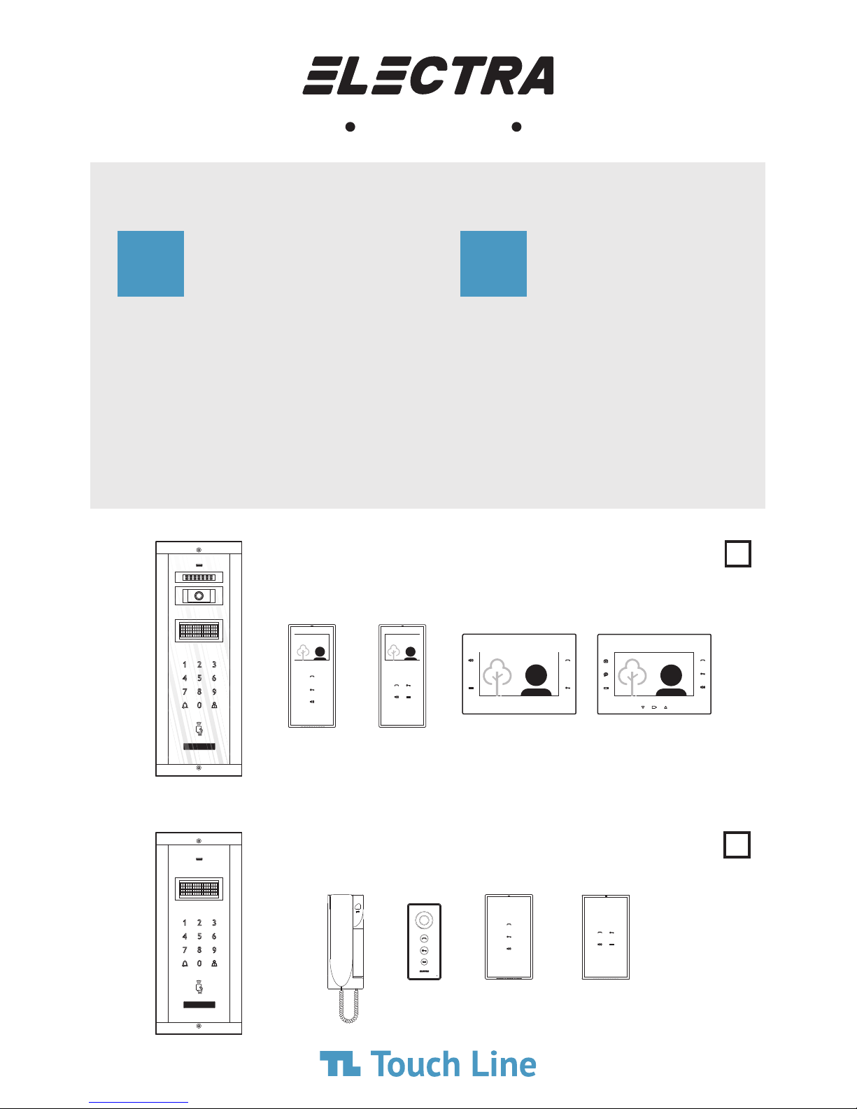
Apartment Buildings
smart smart
+
extra
video
audio
Carte tehnică
INTERFOANE VIDEO & AUDIO
Blocuri de locuințe
smart +
ok
extra
smart +smart
mini smart smart +classic
RO
Page 2

0
IT
CONTENTS
CONTENUTO
0
CONTENTS CUPRINS
1,2
ROENEN
FEATURES & SYSTEM COMPONENTS
pg. 1...12
FUNCȚIUNI & COMPONENȚA INSTALAȚIEI
pg. 1...12
3
BLOCK DIAGRAMS
pg. 13...14
SCHEME BLOC
Video Systems
pg. 15Audio Systems
pg. 16...17Mixed video-audio systems
pg. 13...14Instalații video
pg. 15Instalații audio
pg. 16...17Instalații mixte video-audio
4
SAFETY instructions during installation Instrucțiuni de SIGURANȚĂ în timpul instalării
pg. 19
pg. 18
5
INSTALLATION
pg. 20
INSTALARE
Required cables
pg. 21...22Installation of the video & audio
outdoor panels
pg. 22...23Installation of the video & audio
connection boxes with RJ45 connectors
pg. 20Cabluri recomandate
pg. 24Installation of the video & audio
connection boxes with screw connectors
pg. 25...26Installation of the 7” video terminals
pg. 25...26Installation of the 3.5” video terminals
pg. 26...27Installation of the audio terminals
pg. 29...30Installation of the video central unit
pg. 31Installation of the audio central unit
pg. 32...33Connections checking
pg. 21...22Instalarea panourilor exterioare
video & audio
pg. 22...23Instalarea dozelor de derivație video & audio
cu conectori RJ45
pg. 24Instalarea dozelor de derivație video & audio
cu conectori cu șurub
pg. 25...26Instalarea terminalelor video de 7”
pg. 25...26Instalarea terminalelor video de 3.5”
pg. 26...27Instalarea terminalelor audio
pg. 29...30Instalarea unității centrale video
pg. 31Instalarea unității centrale audio
pg. 32...33Verificarea conexiunilor
6
USE OF THE DOOR PHONE
pg. 34
UTILIZAREA INTERFONULUI
SAFETY instructions during use
pg. 34...35The features of the video & audio
central units
pg. 51Instrucțiuni de SIGURANȚĂ în timpul utilizării
pg. 51...52Funcțiunile unităților centrale
video & audio
pg. 36...40The programming of the
video & audio outdoor panels
pg. 40...41The functioning of the video & audio
outdoor panels
pg. 41...42The programming of the
video & audio terminals
pg. 43...48The functioning of the video & audio
terminals
pg. 53...57Programarea panourilor exterioare
video & audio
pg. 57...58Funcționarea panourilor exterioare
video & audio
pg. 58...59Programarea terminalelor
video & audio
pg. 60...65Funcționarea terminalelor
video & audio
7
TROUBLESHOOTING DEPANARE
pg. 65...67
pg. 48...50
8,9
MAINTENANCE & WARRANTY
pg. 50
ÎNTREȚINERE & GARANȚIE
pg. 67
Page 3
1
1.
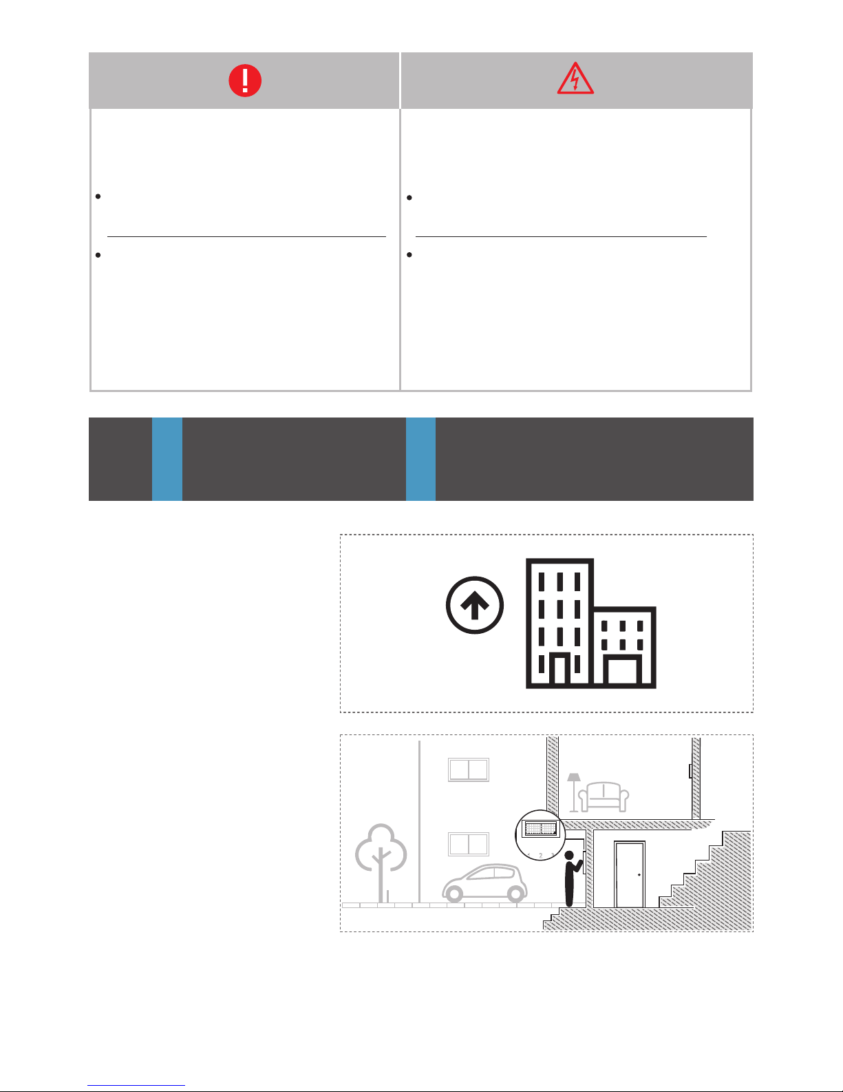
Up to 255 apartments
Până la 255 de apartamente
FEATURES
FUNCȚIUNI
1
EN
IT
EN
RO
255
2.
Electronic resident list
Listă locatari electronică
We lco e
!
m
D i a l n
or
fi
n
a
wi
m
e
umber
nd
t
h
Risk of electric shock!
Authorized personnel required!
Pericol de șoc electric!
Intervenția se face doar de către personal autorizat!
Maximum attention for correct installation/
wire connection.
Atenție maximă pentru corectitudinea instalării/
conectării firelor.
Page 4
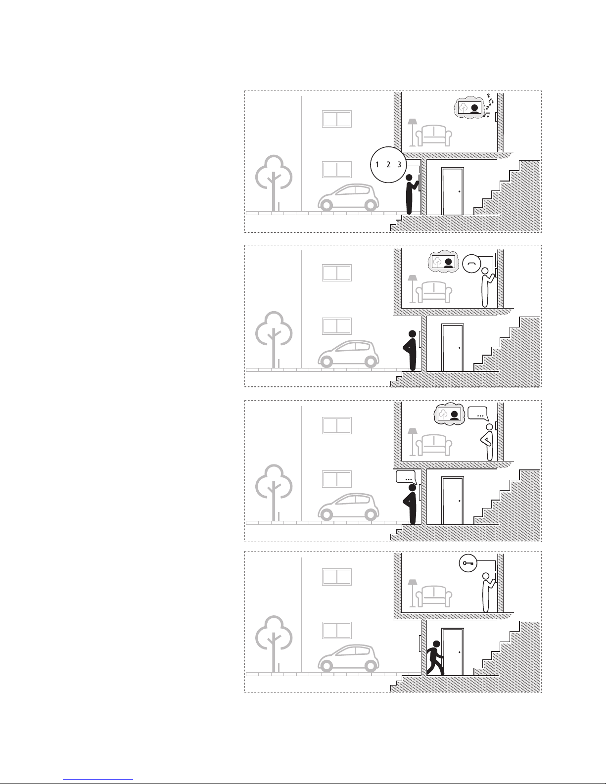
6.
Access granting
Acordare acces
5.
Hands-free talk
Convorbire hands-free
Video + Answer
Video + Răspuns
4.
Call
Apel
3.
2
Page 5
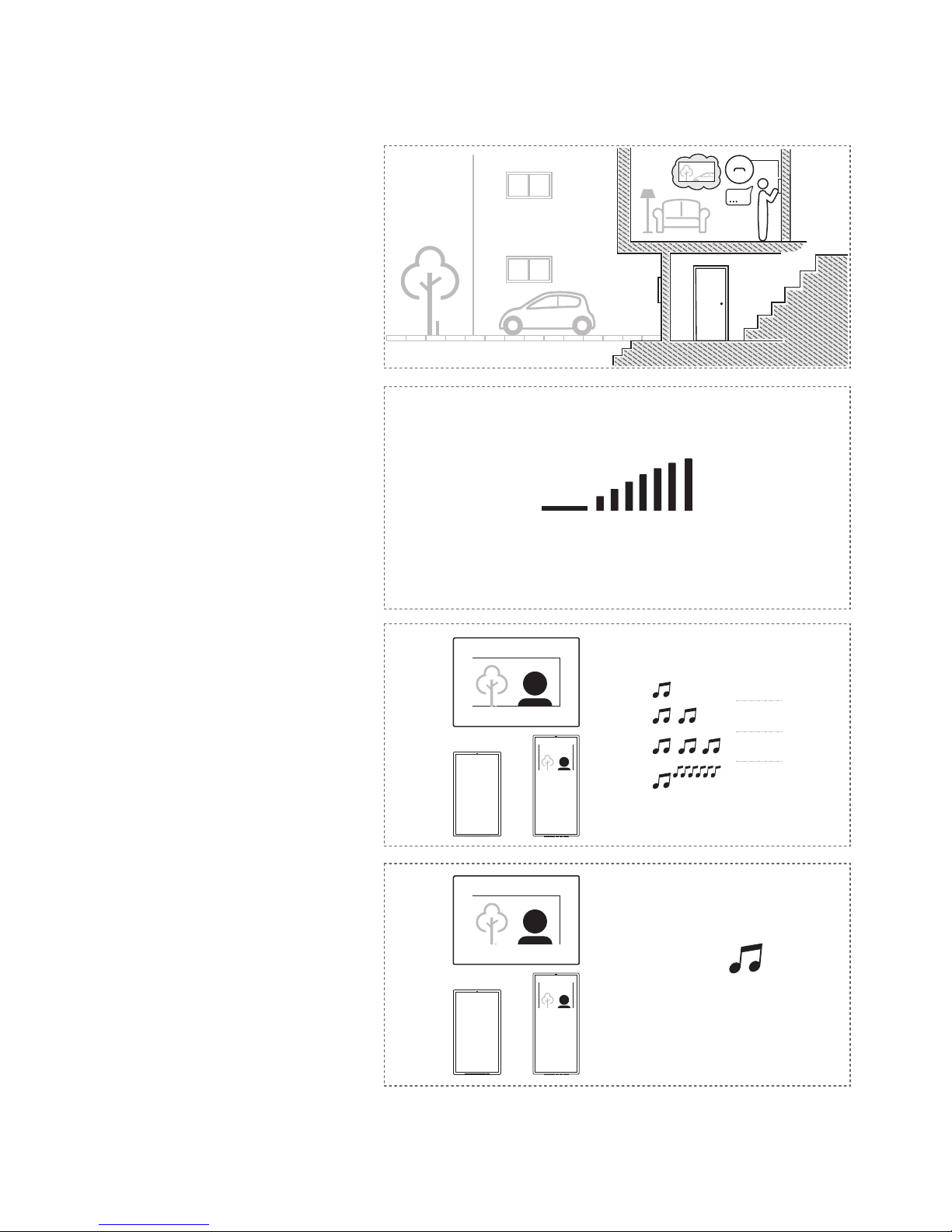
9.
Setting the ringing duration
Setarea duratei apelului
1 min
x
5 sec
x
1
5 sec
x
2
5 sec
x
3
5
x
10.
Multiple ringtones
Mai multe melodii de apel
1 7MUTE
Volume levels
Niveluri de volum
8.
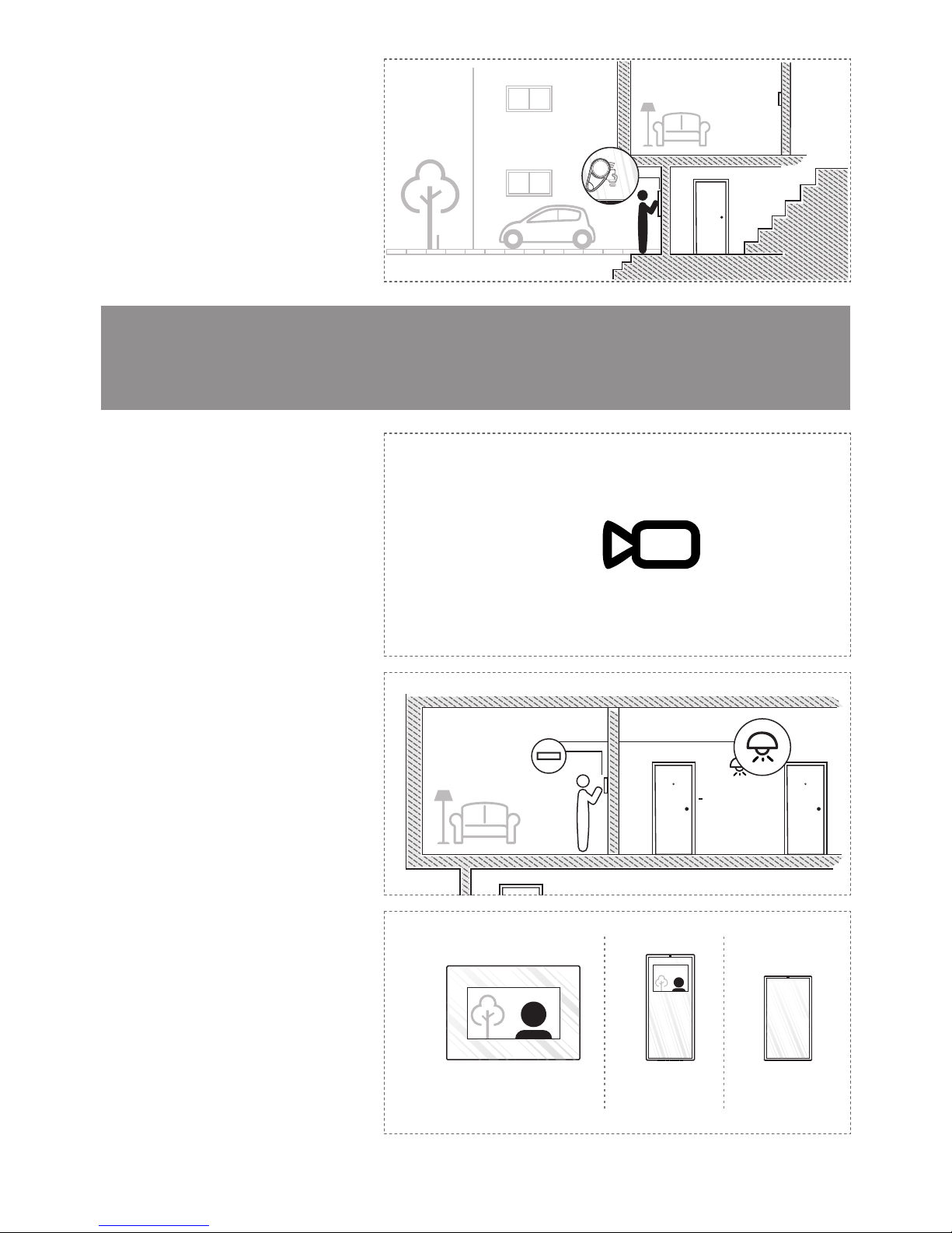
Video & Audio monitoring
Monitorizare video & audio
7.
3
Page 6
Optional features
Funcțiuni opționale
12.
Additional video cameras
Camere video adiționale
13.
Auxiliary command
Comandă auxiliară
14.
Additional terminals
Terminale adiționale
4
x
video 7” audiovideo 3.5”
1
x
1
x
3
x
11.
Access with RFID tag
Acces cu tag RFID
4
Page 7
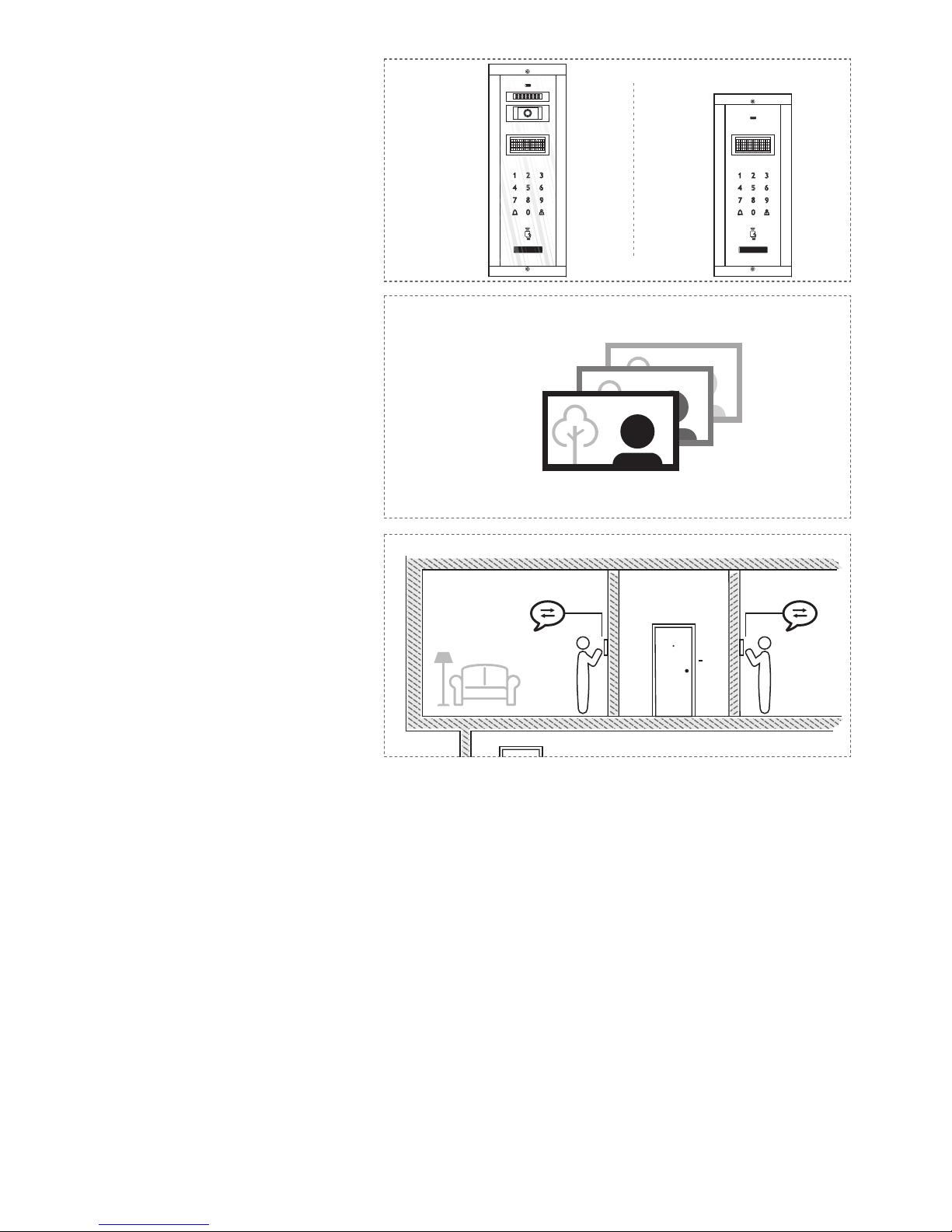
16.
Pictures memory
Memorare imagini
17.
Intercommunication
Intercomunicare
100 x
15.
Additional panels
Panouri adiționale
3
x
3
x
5
Page 8
TAG.ELT
6
2
SYSTEM COMPONENTS
COMPONENȚA INSTALAȚIEI
EN
IT
EN RO
414 x 144 x 53 mm
2,3 kg
o o
- 30 C … + 60 C
12 … 14 Vd.c.
v
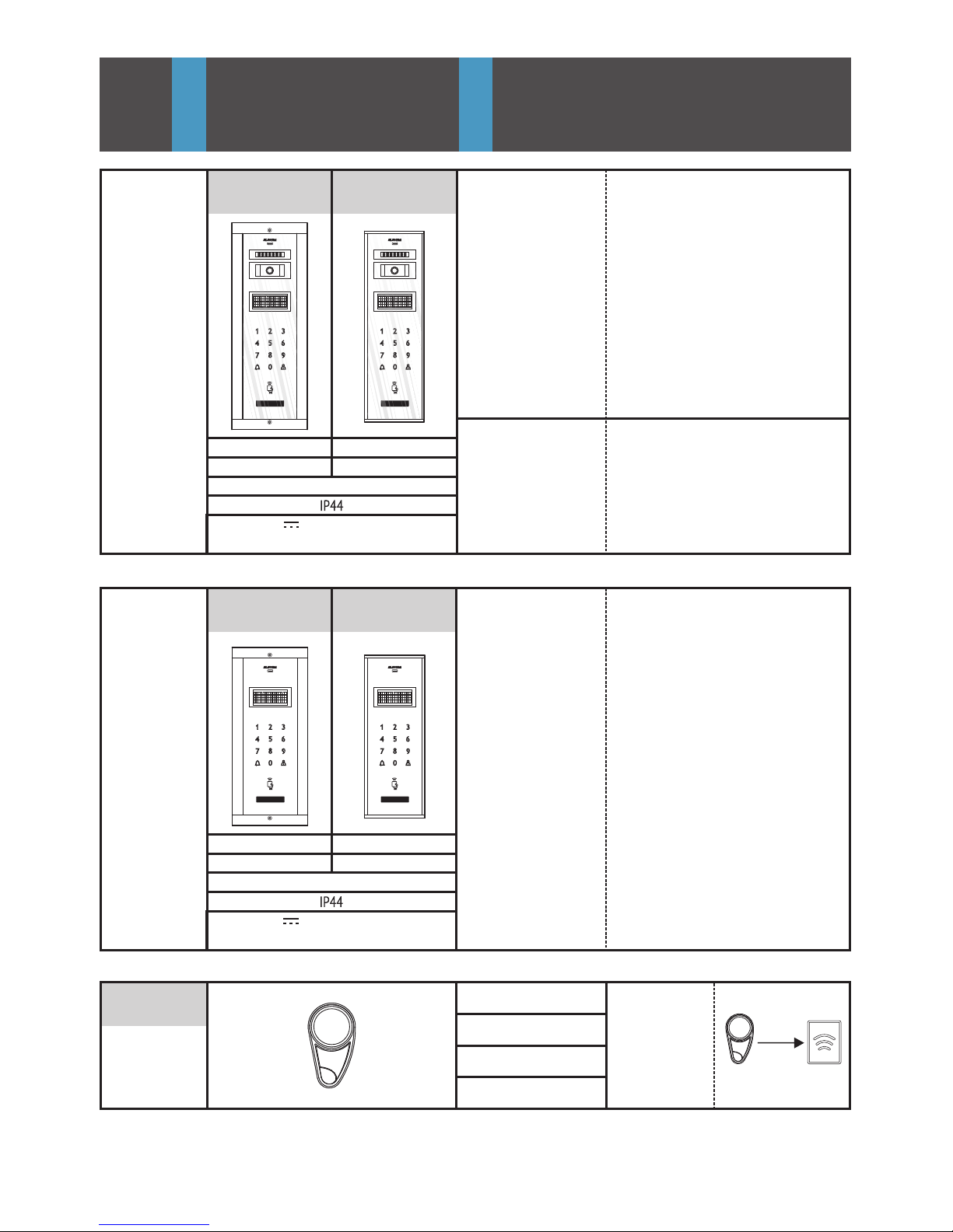
smart Outdoor panel
Panou exterior smart
Case
Carcasă
AL profile + Chemically toughened glass - 8 mm
Profil AL + Sticlă securizată chimic – 8mm
Steerable video camera
Cameră video orientabilă
CMOS, IR-CUT
1/3", 573(H) x 597(V), 800 TVL
video 1 Vpp / 75 W; PAL
12 LEDs = 850 nm ; 7 mW/ LED
o o
75 ± 25
VPM.BFR02
Case
Carcasă
AL profile + Chemically toughened glass - 8 mm
Profil AL + Sticlă securizată chimic – 8mm
APM.BFR02
374 x 144 x 53 mm
2.1 kg
o o
- 30 C … + 60 C
12 … 14 Vd.c.
v
32 x 62 x 7 mm
o o
- 30 C … + 60 C
30 mm
125kHz
ABS, IP65
RFID Tag
Tag RFID
Reading distance
Distanța de citire
380 x 110 x 33 mm
2 kg
VPM.BSR02
340 x 110 x 33 mm
1.8 kg
APM.BSR02
smart Outdoor panel
Panou exterior smart
Page 9
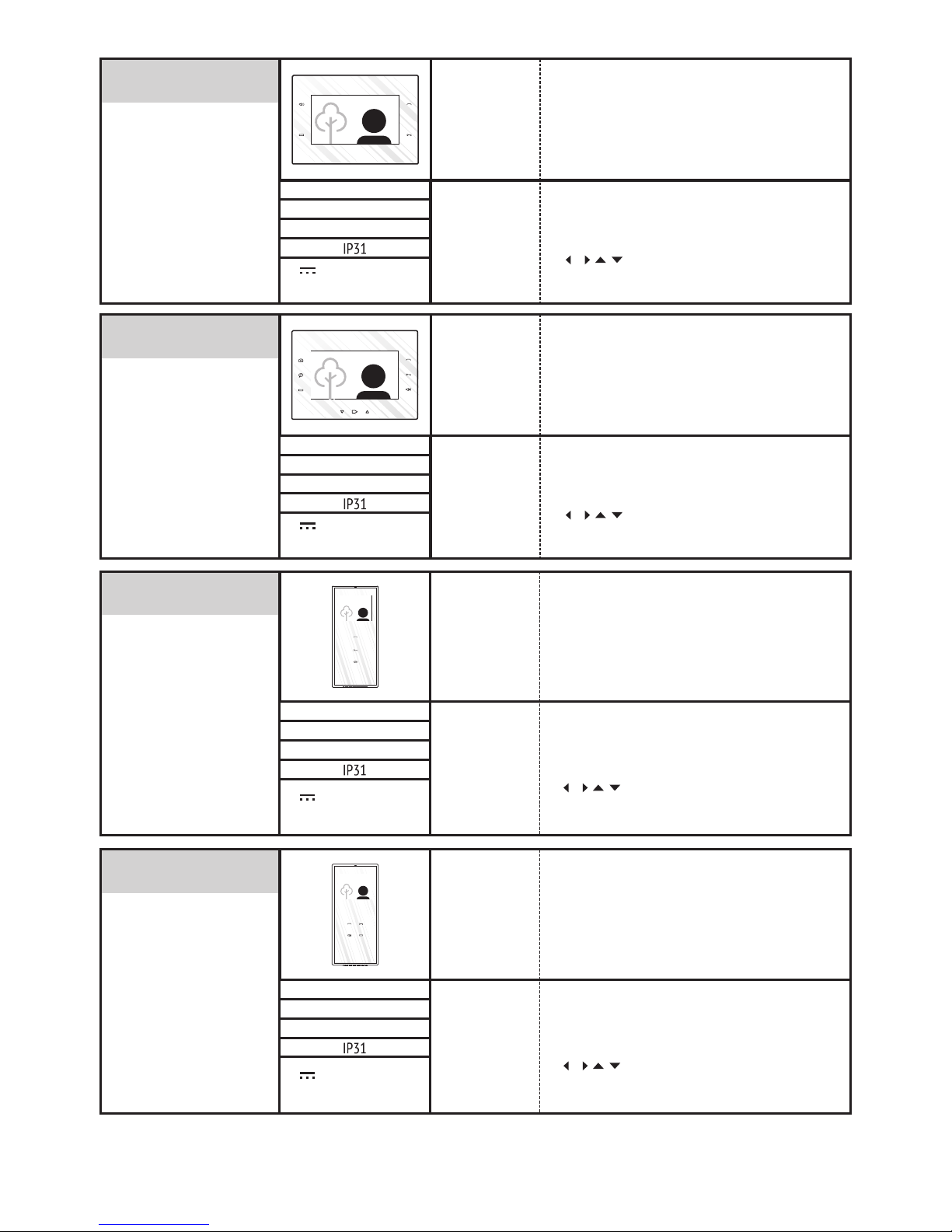
VTM.3S302
VTM.7S402
162 x 227 x 20 mm
0,8 kg
o o
0 C … + 45 C
12 … 14 Vd.c.
v
smart + Video terminal
Terminal video smart +
Case
Carcasă
ABS + Chemically toughened glass - 3 mm
ABS + Sticlă securizată chimic – 3 mm
LCD display
Display LCD
7“ LCD, TFT
800 x 3 (RGB) x 480
/ / / - 60 / 60 / 40 / 60
VTE.7S902
162 x 227 x 20 mm
0,8 kg
o o
0 C … + 45 C
12 … 14 Vd.c.
v
extra Video terminal
Terminal video extra
Case
Carcasă
ABS + Chemically toughened glass - 3 mm
ABS + Sticlă securizată chimic – 3 mm
LCD display
Display LCD
7“ LCD, TFT
800 x 3 (RGB) x 480
/ / / - 60 / 60 / 40 / 60
ok
212 x 96 x 22 mm
0,4 kg
o o
0 C … + 45 C
LCD display
Display LCD
Case
Carcasă
ABS + Chemically toughened glass - 3 mm
ABS + Sticlă securizată chimic – 3 mm
12 … 14 Vd.c.
v
3,5” LCD
320 x (RGB) x 240
/ / / - 60 / 60 / 40 / 60
smart Video terminal
Terminal video smart
VTM.3S402
212 x 96 x 22 mm
0,4 kg
o o
0 C … + 45 C
LCD display
Display LCD
Case
Carcasă
ABS + Chemically toughened glass - 3 mm
ABS + Sticlă securizată chimic – 3 mm
12 … 14 Vd.c.
v
3,5” LCD
320 x (RGB) x 240
/ / / - 60 / 60 / 40 / 60
smart + Video terminal
Terminal video smart +
7
Page 10
ATM.0S302
170 x 96 x 22 mm
0,3 kg
o o
0 C … + 45 C
Case
Carcasă
ABS + Chemically toughened glass - 3 mm
ABS + Sticlă securizată chimic – 3 mm
12 … 14 Vd.c.
v
smart Audio terminal
Terminal audio smart
ATM.0S402
170 x 96 x 22 mm
0,3 kg
o o
0 C … + 45 C
Case
Carcasă
ABS + Chemically toughened glass - 3 mm
ABS + Sticlă securizată chimic – 3 mm
12 … 14 Vd.c.
v
smart + Audio terminal
Terminal audio smart +
ATm.0S302
170 x 74 x 20 mm
0,3 kg
o o
0 C … + 45 C
Case
Carcasă
Plastic
Plastic
12 … 14 Vd.c.
v
mini Audio terminal
Terminal audio mini
ATt.0S102
220 x 83 x 60 mm
0,4 kg
o o
0 C … + 45 C
Case
Carcasă
Plastic
Plastic
12 … 14 Vd.c.
v
classic Audio terminal
Terminal audio classic
8
Page 11
VCB.3DN02
SCU.VDR02
130 x 141 x 73 mm
0,4 kg
o o
0 C … + 45 C
14 V- GND : 14 Vd.c./2 Ad.c.
Uv - GNV : 14 Vd.c./0.5 Ad.c.
Vcam - GND : 12 Vd.c./0.4 Ad.c.
v
Video central unit
Unitate centrală video
Case
Carcasă
Fireproof ABS
ABS ignifugat
DIN rail mounting
Montaj pe șină DIN
TH 35 x 15 / 35 x 7,5
DIN 46277-3, En50022,
IEC60715
SCU.ADN02
100 x 71 x 60 mm
0,2 kg
o o
0 C … + 45 C
14 V- GND : 14 Vd.c./2 Ad.c.
Uv - GNV : 14 Vd.c./0.5 Ad.c.
Vcam - GND : 12 Vd.c./0.4 Ad.c.
v
Audio central unit
Unitate centrală audio
Case
Carcasă
Fireproof ABS
ABS ignifugat
DIN rail mounting
Montaj pe șină DIN
TH 35 x 15 / 35 x 7,5
DIN 46277-3, En50022,
IEC60715
VSB.4DN02.BLW
IN: 4
OUT:
1
: 12-14 V
VCB.3DN02.BLW
OUT: 3
: 12-14 V
BUS
IN-OUT: 1
100 x 71 x 60 mm
0,2 kg
o o
0 C … + 45 C
12 … 14 Vd.c.
v
VSB.4DN02.BLW
IN: 4
OUT:
1
: 12-14 V
VCB.3DN02.BLW
OUT: 3
: 12-14 V
BUS
IN-OUT: 1
ABS
TH 35 x 15 / 35 x 7,5
DIN 46277-3, En50022,
IEC60715
Video connection box
Doză derivație video
Case
Carcasă
DIN rail mounting
Montaj pe șină DIN
VCB.4DR02
100 x 71 x 60 mm
0,2 kg
o o
0 C … + 45 C
12 … 14 Vd.c.
v
VCB.4DR02.ELW
ABS
TH 35 x 15 / 35 x 7,5
DIN 46277-3, En50022,
IEC60715
Video connection box
Doză derivație video
Case
Carcasă
DIN rail mounting
Montaj pe șină DIN
Connections
Conexiuni
Connections
Conexiuni
Connections
Conexiuni
Connections
Conexiuni
Screws
Șuruburi
1 input - 3 outputs
1 intrare - 3 ieșiri
Screws
Șuruburi
1 input - 4 outputs
1 intrare - 4 ieșiri
9
Page 12
ACB.4DR02
100 x 71 x 60 mm
0,2 kg
o o
0 C … + 45 C
12 … 14 Vd.c.
v
VSB.4DN02.BLW
IN: 4
OUT:
1
: 12-14 V
VCB.3DN02.BLW
OUT: 3
: 12-14 V
BUS
IN-OUT: 1
ABS
TH 35 x 15 / 35 x 7,5
DIN 46277-3, En50022,
IEC60715
Audio connection box
Doză derivație audio
Case
Carcasă
DIN rail mounting
Montaj pe șină DIN
VCB.10DR02
130 x 141 x 73 mm
0,4 kg
o o
0 C … + 45 C
12 … 14 Vd.c.
v
ABS
TH 35 x 15 / 35 x 7,5
DIN 46277-3, En50022,
IEC60715
Video connection box
Doză derivație video
Case
Carcasă
DIN rail mounting
Montaj pe șină DIN
ACB.4DN02
100 x 71 x 60 mm
0,2 kg
o o
0 C … + 45 C
12 … 14 Vd.c.
v
ACB.4DN02.ELW
ABS
TH 35 x 15 / 35 x 7,5
DIN 46277-3, En50022,
IEC60715
Audio connection box
Doză derivație audio
Case
Carcasă
DIN rail mounting
Montaj pe șină DIN
Connections
Conexiuni
Connections
Conexiuni
Connections
Conexiuni
Screws
Șuruburi
1 input - 4 outputs
1 intrare - 4 ieșiri
1 input - 10 outputs
1 intrare - 10 ieșiri
BAT
LCK
1 x
Direct current (DC) or Alternative current (AC) lock
Yală de curent continuu (c.c.) sau curent alternativ (c.a.)
Rechargeable battery
Acumulator
1 x
BAT
12V/7Ah
12Vd.c., 1 Ad.c.
max. 24Va.c., 1 Aa.c.
12V / 7Ah video
12V / 3.2Ah audio
Additional products (separately purchased)
Produse adiționale (achiziționate separat)
1 input - 4 outputs
1 intrare - 4 ieșiri
10
Page 13
ATM.0S302
ATM.0S402
VTM.3S302
VTM.3S402
VTM.7S402
VTE.7S902
Video terminal in parallel
Terminal video în paralel
Up to 3 audio terminals in parallel
Până la 3 terminale audio în paralel
3 x
170 x 96 x 22 mm
3,5” LCD
320 x (RGB) x 240
/ / / - 60/ 60/ 40 / 60
212 x 96 x 22 mm
1 x
7“ LCD, TFT
800 x 3 (RGB) x 480
/ / / - 60/ 60/ 40 / 60
227 x 162 x 20 mm
1 x
Video terminal in parallel
Terminal video în paralel
VSB.4DN(R)
Video selection box with 4 inputs and 1 output
Doză selecție video cu 4 intrări și 1 ieșire
Video selection box for additional video cameras and/
or panels
Doză selecție video pentru panouri/ camere adiționale
1 x
VSB.4DN02.BLW
IN: 4
OUT:
1
: 12-14 V
VPM.BF(S)R02
APM.BF(S)R02
+
+
3 x SCU
1 x VSB
+
3 x LCK
Up to 3 outdoor panels in parallel
Până la 3 panouri în paralel
3 x
11
PRG
Programator adrese terminale
Programmer for terminals addresses
1 x
Page 14

DVA.4PS02
SWC
DVA.1PS02
Vcam
Vcam
PVB
+
1 x PVB
+
4 x PVB
1 x VSB
+
1 x
4 x
1 x
VSB.4DN02.BLW
IN: 4
OUT:
1
: 12-14 V
1 video camera connected directly in SCU.VDR02
1 cameră video conectată direct în SCU.VDR02
Passive video balun
Balun video
For additional video cameras
Pentru camere adiționale
Open door switch
Buton deschidere ușă
Non-Latching
Fără blocare
Differential video amplifier
Amplificator video diferențial
Up to 4 video cameras (12 Vd.c. power supply for each)
Până la 4 camere video (fiecare cu sursă de alimentare
de 12 Vc.c.)
1 x
Differential video amplifier
Amplificator video diferențial
12
SAC
Additional power supply
Sursă alimentare suplimentară
1 x
SAC
12...14Vd.c
Page 15
LCK
UTP cat5e
(AWG 24)
UTP cat5e
(AWG 24)
SCU.VDR
Vcam
VPM
UTP cat5e
(AWG 24)
2
2 x 0.75 mm
BAT
2
2 x 0.75 mm
230 Va.c., 50 Hz
2
3 x 0.75 mm
12V 7Ah
/
PVB
AUX
SWC
2 x 6Aa.c.
2
2 x 0.75 mm
S1 S2 S3
PROG
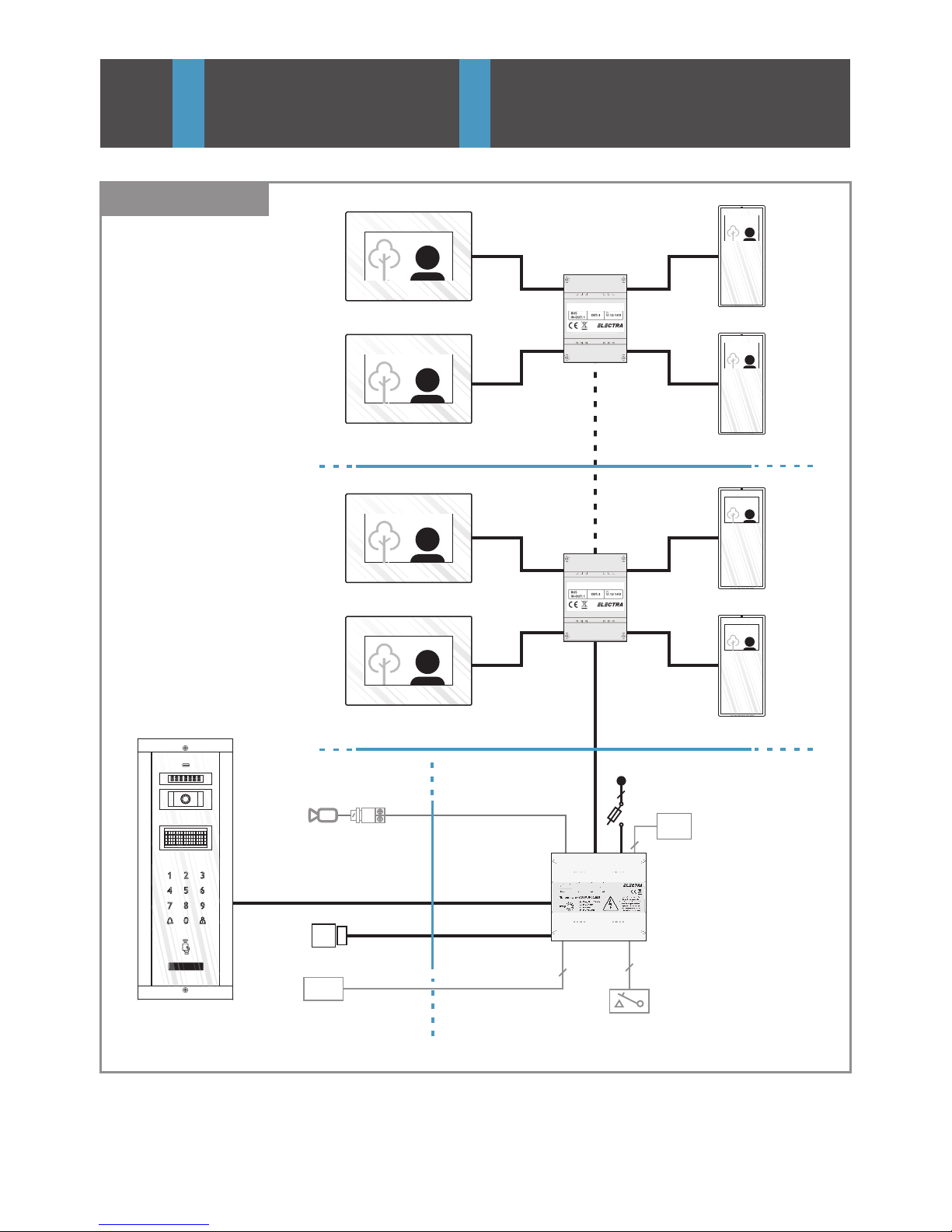
STROMVERSORGUNGSEINHEIT (SCU.VDR02.BLW)
SCHLOSS-
ÖFFNUNGS-
ZEIT
(sekunden)
EINGANG: 230V Wechselspannung 50Hz, 0.4A
AUSGANG 1: 14V, 2A Gleichspannung (S1)
AUSGANG 2: 14V, 0.5A Gleichspannung (S2)
BATTERIESTATUS: S3
ACHTUNG! Lebensgefahr,
Gerät nicht öffnen!
GEFAHR EINES
STROMSCHLAGS!
10
5
6
1
2
3
4
7
8
9
VTM(E)
VTM(E)
VTM
VTM
VTM(E)
VTM(E)
VTM
VTM
3
BLOCK DIAGRAMS SCHEME BLOC
EN
IT
EN RO
3.1.1
UTP cat5e
(AWG 24)
VCB.4DR02.ELW
VCB.4DR02.ELW
VCB.4DR
VCB.4DR
VIDEO
13
Page 16
LCK
UTP cat5e
(AWG 24)
UTP cat5e
(AWG 24)
SCU
Vcam
VPM
2
2 x 0.75 mm
BAT
2
2 x 0.75 mm
230 Va.c., 50 Hz
2
3 x 0.75 mm
12V 7Ah
/
PVB
AUX
SWC
2 x 6Aa.c.
2
2 x 0.75 mm
S1 S2 S3
PROG
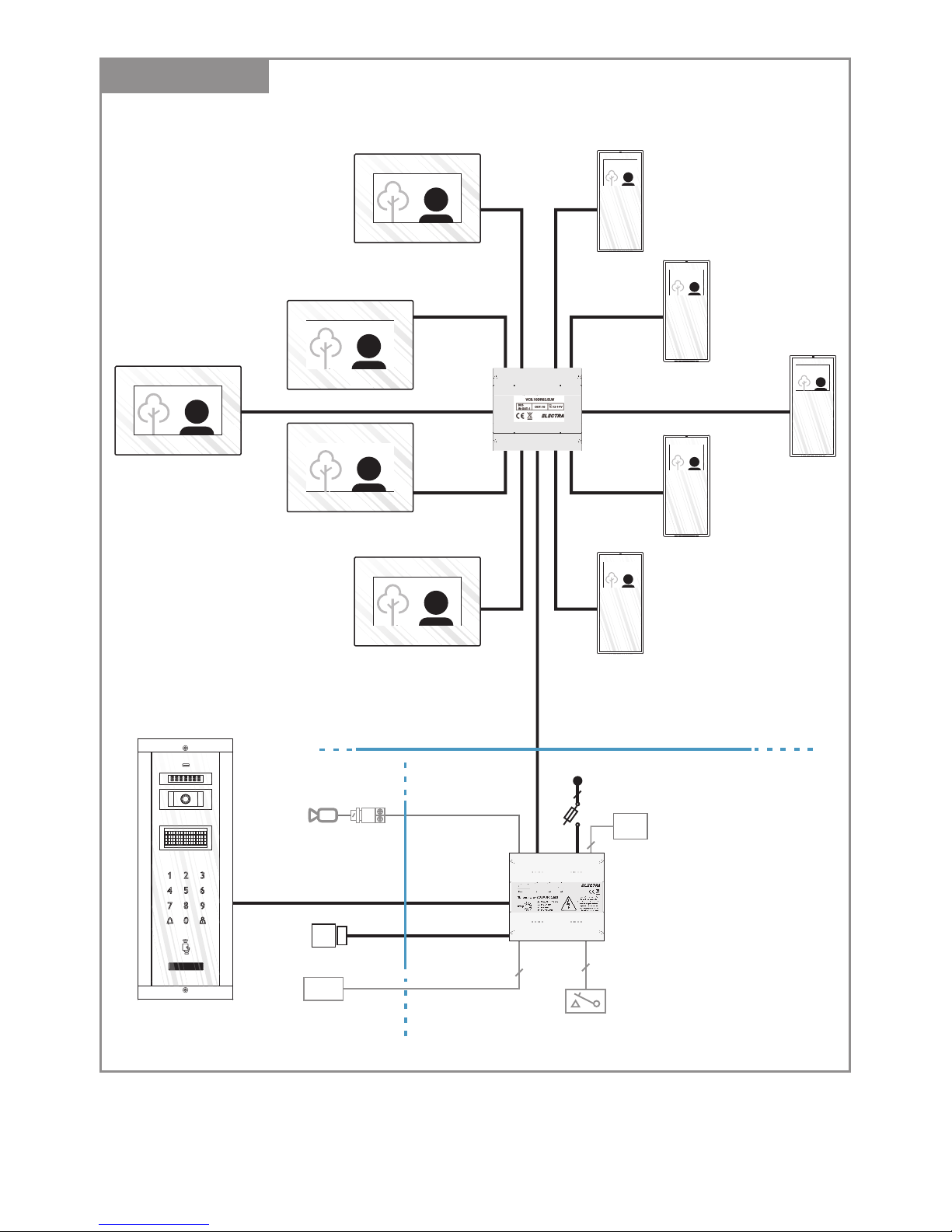
STROMVERSORGUNGSEINHEIT (SCU.VDR02.BLW)
SCHLOSS-
ÖFFNUNGS-
ZEIT
(sekunden)
EINGANG: 230V Wechselspannung 50Hz, 0.4A
AUSGANG 1: 14V, 2A Gleichspannung (S1)
AUSGANG 2: 14V, 0.5A Gleichspannung (S2)
BATTERIESTATUS: S3
ACHTUNG! Lebensgefahr,
Gerät nicht öffnen!
GEFAHR EINES
STROMSCHLAGS!
10
5
6
1
2
3
4
7
8
9
3.1.2
VIDEO
UTP cat5e
(AWG 24)
VTM(E)
VTM(E)
VTM(E)
VTM
VCB.10DR
VTM
VTM
UTP cat5e
(AWG 24)
VTM
VTM(E)
VTM(E)
VTM
14
Page 17
LCK
UTP cat5e
(AWG 24)
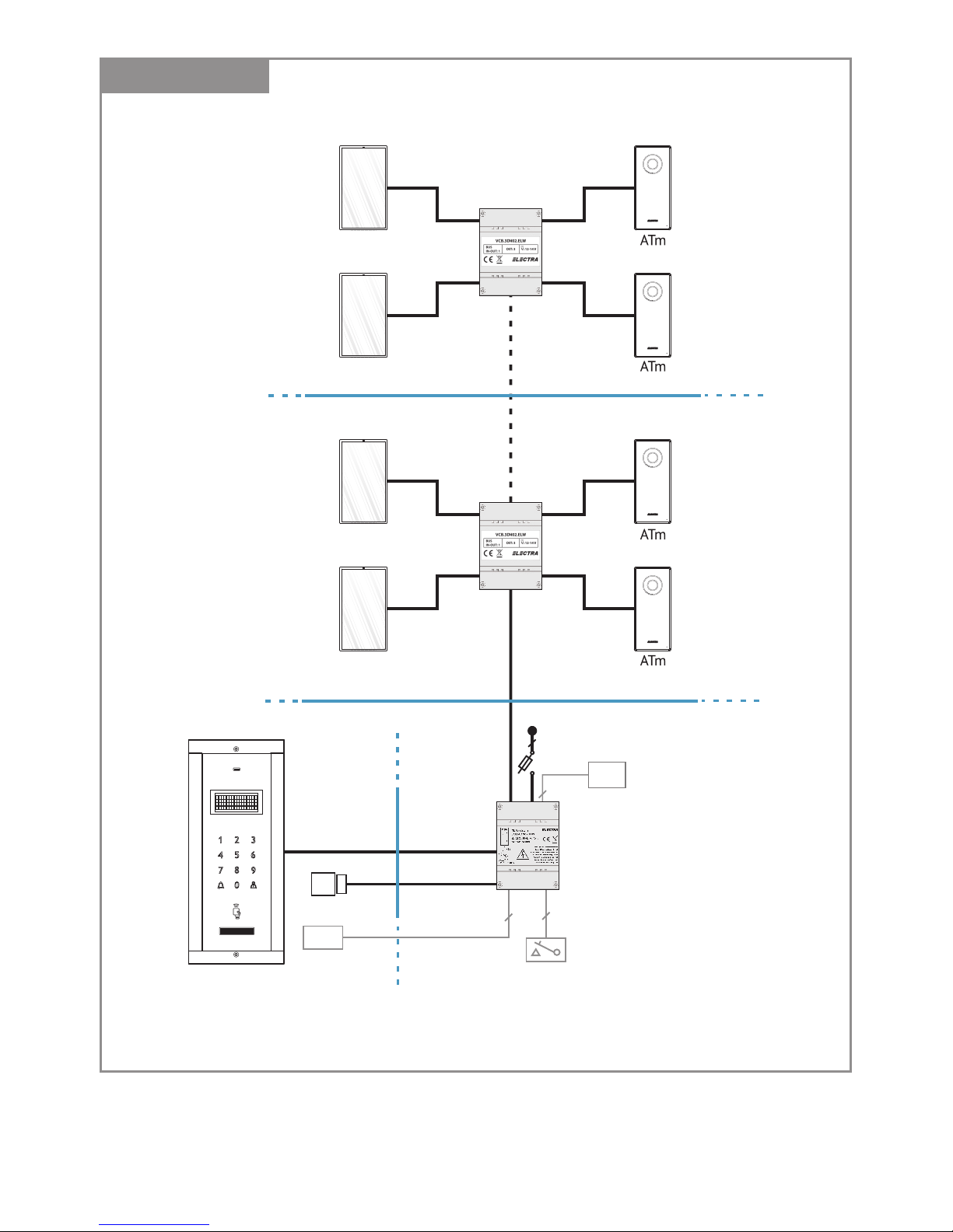
SCU.ADN
APM
BAT
2
2 x 0.75 mm
230 Va.c., 50 Hz
2
3 x 0.75 mm
12V 3.2Ah
/
AUX
SWC
2 x 6Aa.c.
2
2 x 0.75 mm
UTP cat5e
(AWG 24)
VSB.4DN02.BLW
IN: 4
OUT:
1
: 12-14 V
VCB.3DN02.BLW
OUT: 3
: 12-14 V
BUS
IN-OUT: 1
2
2 x 0.75 mm
VSB.4DN02.BLW
IN: 4
OUT:
1
: 12-14 V
VCB.3DN02.BLW
OUT: 3
: 12-14 V
BUS
IN-OUT: 1
ATM
ATM
VSB.4DN02.BLW
IN: 4
OUT:
1
: 12-14 V
VCB.3DN02.BLW
OUT: 3
: 12-14 V
BUS
IN-OUT: 1
ATM
ATM
3.1.3
ACB.4DR
AUDIO
ACB.4DR
15
Page 18
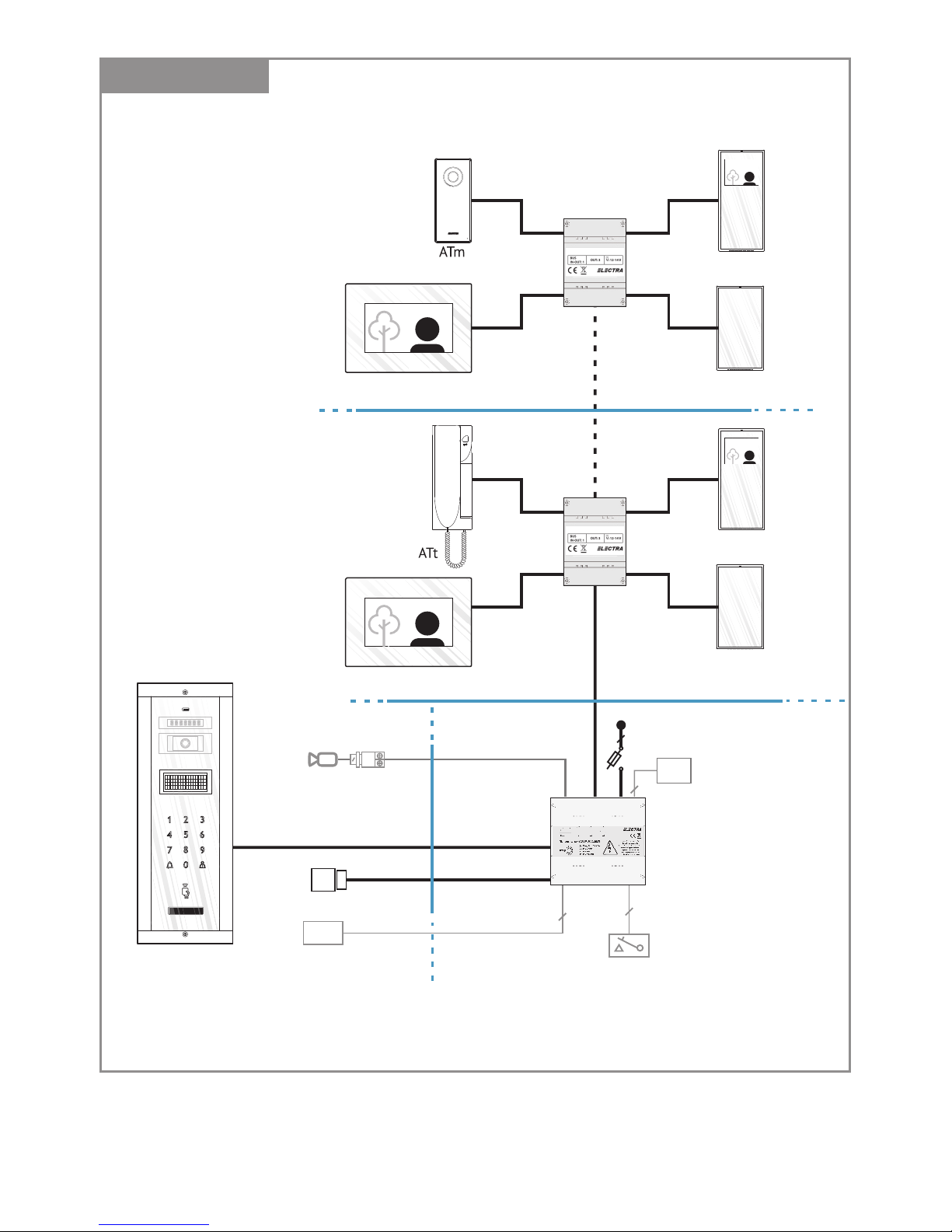
3.1.4
LCK
UTP cat5e
(AWG 24)
UTP cat5e
(AWG 24)
SCU.VDR
Vcam
VPM
2
2 x 0.75 mm
BAT
2
2 x 0.75 mm
230 Va.c., 50 Hz
2
3 x 0.75 mm
12V 7Ah
/
PVB
AUX
SWC
2 x 6Aa.c.
2
2 x 0.75 mm
S1 S2 S3
PROG
STROMVERSORGUNGSEINHEIT (SCU.VDR02.BLW)
SCHLOSS-
ÖFFNUNGS-
ZEIT
(sekunden)
EINGANG: 230V Wechselspannung 50Hz, 0.4A
AUSGANG 1: 14V, 2A Gleichspannung (S1)
AUSGANG 2: 14V, 0.5A Gleichspannung (S2)
BATTERIESTATUS: S3
ACHTUNG! Lebensgefahr,
Gerät nicht öffnen!
GEFAHR EINES
STROMSCHLAGS!
10
5
6
1
2
3
4
7
8
9
VTM(E)
VTM
UTP cat5e
(AWG 24)
VCB.4DR02.ELW
ATM
VTM(E)
VTM
UTP cat5e
(AWG 24)
VCB.4DR02.ELW
ATM
AUDIO - VIDEO
VCB.4DR
VCB.4DR
16
Page 19

UTP cat5e
(AWG 24)
SCU
VSB
UTP cat5e
(AWG 24)
UTP cat5e
(AWG 24)
VPM
UTP cat5e
(AWG 24)
VSB(ACB)
SCU1
SCU2
SCU3
SCU4
V(A)PM1
V(A)PM2 V(A)PM3 V(A)PM4
UTP cat5e (AWG 24)
Vcam1
Vcam2
Vcam3
Vcam4
UTP cat5e
(AWG 24)
UTP cat5e (AWG 24)
PVB
PVB
PVB
PVB
3.3.
3.4.
230V
50Hz
230V
50Hz
230V
50Hz
230V
50Hz
230V
50Hz
VTM(E)
UTP cat5e
(AWG 24)
UTP cat5e
(AWG 24)
VTM(E)2
VCB
3.2.
VCB
VCB(ACB)
S1 S2 S3
PROG
STROMVERSORGUNGSEINHEIT (SCU.VDR02.BLW)
SCHLOSS-
ÖFFNUNGS-
ZEIT
(sekunden)
EINGANG: 230V Wechselspannung 50Hz, 0.4A
AUSGANG 1: 14V, 2A Gleichspannung (S1)
AUSGANG 2: 14V, 0.5A Gleichspannung (S2)
BATTERIESTATUS: S3
ACHTUNG! Lebensgefahr,
Gerät nicht öffnen!
GEFAHR EINES
STROMSCHLAGS!
10
5
6
1
2
3
4
7
8
9
VSB.4DN02.BLW
IN: 4
OUT:
1
: 12-14 V
VSB.4DN02.BLW
IN: 4
OUT:
1
: 12-14 V
S1 S2 S3
PROG
STROMVERSORGUNGSEINHEIT (SCU.VDR02.BLW)
SCHLOSS-
ÖFFNUNGS-
ZEIT
(sekunden)
EINGANG: 230V Wechselspannung 50Hz, 0.4A
AUSGANG 1: 14V, 2A Gleichspannung (S1)
AUSGANG 2: 14V, 0.5A Gleichspannung (S2)
BATTERIESTATUS: S3
ACHTUNG! Lebensgefahr,
Gerät nicht öffnen!
GEFAHR EINES
STROMSCHLAGS!
10
5
6
1
2
3
4
7
8
9
Additional terminals
Terminale adiționale
Additional video cameras
Camere video adiționale
Additional panels
Panouri adiționale
VTM2
UTP cat5e
(AWG 24)
VCB
UTP cat5e
(AWG 24)
VTM
VTM2 VTM(E)2
VTM VTM(E)
UTP cat5e
(AWG 24)
VCB
UTP cat5e
(AWG 24)
ATM2 ATM3 ATM4
ATM
VCB
ATM2 ATM3 ATM4
17
Page 20
SAFETY INSTRUCTIONS
during installation
4
EN
4.1. Installation steps
1. ATTENTION! The installation, the maintenance and the connection to the 230V/50Hz network
of the central unit (SCU) will be carried out only by authorized personnel!
2
2. ATTENTION! It is MANDATORY to use a 3 x 0,75 mm cable and 2 automatic fuses (6A) for
power supplying the central unit (SCU) from the 230V/50Hz network.
3. ATTENTION! During installation, connection of the central unit (SCU) to 230V/50Hz and
service, the safety fuses from the electric panel must be opened ( ).POWER OFF
4. ATTENTION! DO NOT UNFASTEN THE FRONT LID OF THE CENTRAL UNIT (SCU)! DANGER OF
ELECTRIC SHOCK! Only 1 and 2 protection lids of the connections can be unfastened during
installation or service.
5. IMPORTANT! You must make the connections for F, N and and mount the 1 and 2 protection
lids of the central unit (SCU) and only after these you can connect the 2 supply fuses (230V/50Hz)
6. DO NOT TOUCH the metallic parts of the wires or the terminals of the connectors from the
central unit (SCU) or from the fuses. You have to disconnect first the 6 A fuses ( ) fromPOWER OFF
the supply's phase and only then you can work with the central unit (SCU).
7. ATTENTION! Do not supply components of the installation separately (outdoor panel, terminals etc.)
at voltages higher than 14Vd.c. or directly from the network (230V/50Hz). DANGER OF ELECTRIC
SHOCK and system destruction.
8. PAY ATTENTION to the polarity of the terminals of the rechargeable battery (max. 7 Ah/ 12 Vd.c.)
when connecting it to the central unit (SCU).
Step 1
Install the Outdoor Panel – Ch. 5.2.
!
Step 3
Install the Terminals – Ch. 5.4.
!
Install the Central Unit (SCU) – Ch. 5.5. Authorized personnel required! – Ch. 4
With the 6A automatic fuses in OFF position:
a. Place the SCU in the electric panel.
b. Make in the SCU the connections for VPM / APM, VTM / ATM, LCK, e.t.c.
c. Make the F, N and connections in SCU.
d. Make the F, N connections at the automatic fuses and to the ground.
!
Step 4
Step 5
Check the precision of all the connections made in SCU.
Step 6
Turn ON the 6A automatic fuses.
Step 7
Check the LEDs colors of SCU – Ch. 6.3. In case of red signaling of any LED, turn OFF the
6A automatic fuses and see TROUBLESHOOTING – Ch. 7 to identify the cause.
With a voltmeter set on direct current, check the voltages on the terminals of SCU, VPM / APM,
VTM / ATM and VCB / ACB - Ch. 5.6.
If the values do not match, see TROUBLESHOOTING – Ch. 7 and identify the cause.
Step 8
Step 9
Check the correct functioning and settings changing - Ch. 6.
Step 2
Install the Connection Boxes – Ch. 5.3.
!
18
Page 21
INSTRUCȚIUNI DE SIGURANȚĂ
în timpul instalării
4
RO
4.1. Etapele instalării
1. ATENȚIE! Instalarea, întreținerea și conectarea unității centrale (SCU) la rețeaua de 230V/50Hz se
va face numai de către personal autorizat!
2. ATENȚIE! Este obligatorie utilizarea unui cablu de 3 x 0,75 și a 2 siguranțe automate (6A) pentru
alimentarea unității centrale (SCU) de la rețeaua de 230V/50Hz.
3. ATENȚIE! În timpul instalării, conectării unității centrale (SCU) la230V/50Hz și service-ului,
siguranțele de protecție din tabloul electric trebuie să fie deconectate ( ).ALIMENTARE OPRITĂ
4. ATENȚIE! NU DEMONTAȚI CAPACUL FRONTAL AL UNITĂȚII CENTRALE (SCU)! PERICOL DE ȘOC
ELECTRIC! Numai capacele de protecție 1 și 2 ale conexiunilor pot fi demontate în timpul instalării
sau service-ului.
5. IMPORTANT! Trebuie făcute conexiunile pentru F, N și și montate capacele de protecție 1 și 2
și abia după aceea se pot conecta cele 2 siguranțe automate (230V/50Hz).
6. NU ATINGEȚI partea metalică a firelor sau bornele de conexiune ale unității centrale (SCU) sau ale
siguranțelor. Trebuie să deconectați mai intâi siguranțele de 6A ( ) de la fazaALIMENTARE OPRITĂ
alimentării și abia după aceea puteți lucra cu unitatea centrală (SCU).
7. ATENȚIE! Nu alimentați separat componente ale instalației (panou exterior, terminale, etc.)
la tensiuni mai mari de 14 V c.c. sau direct la rețea (230V/50Hz). PERICOL DE ȘOC ELECTRIC și de
distrugere a instalației.
8. ATENȚIE la polaritatea bornelor acumulatorului (max. 7 Ah/ 12 Vc.c.) în momentul conectării lui la
unitatea centrală (SCU).
Pas 1
Instalați panoul exterior - Cap. 5.2.
!
Pas 3
Instalați terminalele – Cap. 5.4.
!
Instalați unitatea centrală (SCU) – Cap. 5.5. Numai personal autorizat! – Cap. 4
Cu siguranțele automate de 6A deconectate:
a. Amplasați SCU în tabloul electric.
b. Faceți în SCU conexiunile pentru VPM / APM, VTM / ATM, LCK, etc..
c. Faceți în SCU conexiunile pentru F, N și .
d. Faceți conexiunile F, N la siguranțele automate și la pământ.
!
Pas 4
Pas 5
Verificați corectitudinea conexiunilor în SCU.
Pas 6
Conectați siguranțele automate de 6A.
Pas 7
Verificați culoarea LED-urilor de pe SCU – Cap. 6.3. În cazul în care unul din LED-uri este roșu,
verificați DEPANAREA – Cap. 7 și identificați cauza.
Verificați cu un voltmetru setat pe curent continuu tensiunile la bornele SCU, VPM / APM,
VTM / ATM și VCB / ACB – Cap. 5.6. Dacă valorile nu corespund, verificați DEPANAREA
– Cap. 7 și identificați cauza.
Pas 8
Pas 9
Verificați corectitudinea funcționării și a schimbării setărilor - Cap. 6.
Pas 2
Instalați dozele de derivație – Cap. 5.3.
!
19
Page 22
5
5.1.
INSTALLATION INSTALARE
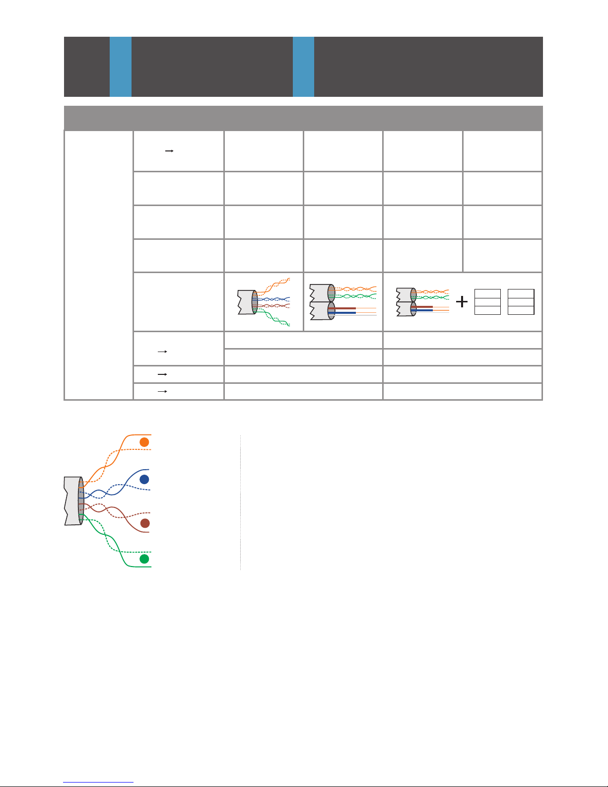
Required cable
Cablul necesar
brown / white
brown
blue / white
blue
orange
orange / white
green/ white
green
UTP cat 5e
(AWG24)
2
3
1
4
maro / alb
maro
albastru / alb
albastru
portocaliu
portocaliu / alb
verde/ alb
verde
ENITEN RO
2
2 / 3 x 0,75 mm
2
2 / 3 x 1 mm
2
3 x 0,75 mm
UTP cat 5e (AWG24)
SCU LCK
230 Vac 50HzSCU
SCU Vcam
≤ 50 m
≤ 100 m
≤ 100 m
≤ 100 m
UTP cat 5e (AWG24)
UTP cat 5 (AWG24)
+ 3 x 0.75
UTP cat 5 (AWG24)
+ 3 x 0.75
+ DVA.1PS02
UTP cat 5 (AWG24)
+ 3 x 0.75
DVA.1PS02 + SAC
VPM
APM
VTM(E),
ATM
Audio
Audio + Video 3.5”
Audio + Video 7”
200 m
100 m
50 m
400 m
200 m
120 m
400 m
400 m
300 m
SACDVA
600 m
600 m
500 m
20
Page 23

150
cm
o
70
5.2. VPM / APM
5.2.1
5.2.2
170
cm
≈20cm
5cm
Installation of the outdoor panel
Instalarea panoului exterior
Flush version
Versiunea îngropată
1.5
cm
≈20cm
5.2.3
Surface version
Versiunea pe suprafață
Antitheft protection. Screw the Torx 2 completely!
Protecție antifurt. Înșurubați complet Torx 2!
o o o
+25 75 +25
o
25
o
75
o
75
o
25
5.2.4
Camera positioning
Poziționarea camerei
Torx 1
Torx 2
Torx 2
5.2.5
Electrical connections
Conexiuni electrice
SCU
+14
V
CD
GND
Vout
GNV
UTP cat5e
(AWG 24)
VPM
1
2
3
4
video
P
21
Page 24

5.2.6
SCU
+14
V
CD
GND
UTP cat5e
(AWG 24)
APM
1
2
3
4
Electrical connections
Conexiuni electrice
5.3. VCB / ACB
5.3.1
Installation of the connection box
Instalarea dozei de derivație
audio
P
DIN
1
2
VCB.3DN02.BLW
OUT: 3
: 12-14 V
BUS
IN-OUT: 1
A
VCB.4DN02.ELW
3
3
5.3.2
GND
+14
+Uv
VTM(E) 2
VTM(E) 1
UTP cat5e
(AWG 24)
SCU/VCB
UTP cat5e
(AWG 24)
UTP cat5e
(AWG 24)
VCB.4DR02.ELW
GND
+14
+Uv
SCU
UTP cat5e
(AWG 24)
(Optional)
3
1
2
4
SCU/VCB
UTP cat5e
(AWG 24)
Electrical connections with RJ45 connector
Conexiuni electrice cu conector RJ45
VTM(E) 4
VTM(E) 3
VCB
22
Page 25

SCU
UTP cat5e
(AWG 24)
3
1
2
4
GND
+14
+Uv
VCB.10DR02.ELW
GND
+14
+Uv
SCU/VCB
VTM(E) 5VTM(E) 4VTM(E) 3VTM(E) 2VTM(E) 1
VTM(E) 10VTM(E) 9VTM(E) 8VTM(E) 7VTM(E) 6
VCB
(Optional)
GND
SCU/ACB
UTP cat5e
(AWG 24)
ACB.4DR02.ELW
GND
SCU
UTP cat5e
(AWG 24)
3
1
2
4
SCU / ACB
UTP cat5e
(AWG 24)
UTP cat5e
(AWG 24)
ATM 2
ATM 1
UTP cat5e
(AWG 24)
ACB
ATM 3
ATM 4
(Optional)
23
GND
+14
GND
+14
Page 26

5.3.3
GND
+14
+Uv
GNV
Vin
Uv
GND
CD
+14
GNV
Vout
Uv
GND
CD
+14
1
2
3
4
1
2
3
4
V
CB.
3
DN
0
2.EL
W
VTM(E) 1
UTP cat5e
(AWG 24)
UTP cat5e
(AWG 24)
VTM(E) 2
GNV
Vout
Uv
GND
CD
+14
1
2
3
4
UTP cat5e
(AWG 24)
VCB
1
2
3
4
GNV
Vin
Uv
GND
CD
+14
SCU
UTP cat5e
(AWG 24)
GND
+14
+Uv
SCU
UTP cat5e
(AWG 24)
(Optional)
3
1
2
4
Electrical connections with screw connectors
Conexiuni electrice cu conectori cu șurub
1
2
3
4
1
2
3
4
1
2
3
4
1
2
3
4
GND
CD
+14
GND
CD
+14
GND
CD
+14
GND
CD
+14
GND
CD
+14
GND
CD
+14
ACB.4DN02.ELW
IN
OUT
12
4 3
ATM3
UTP cat5e
(AWG 24)
SCU/ACB
UTP cat5e
(AWG 24)
ATM 2
UTP cat5e
(AWG 24)
ATM 1
UTP cat5e
(AWG 24)
1
2
3
4
ATM4
UTP cat5e
(AWG 24)
1
2
3
4
ACB
24
Page 27

170 cm
135 cm
≈20cm
UTP cat5e
(AWG 24)
5.4. VTM / VTE / ATM
5.4.1.1
1
2
VTM(E) -7”
1
2
5.4.1.2
5.4.1.3
V
out
GN
Vo
u
t
+
UV
GN
D
C
D
+1
4V
DBL
2
D
BL1
V
i
n
GN
Vi
n
Türklingel
Doorbell
UTP cat5e
(AWG 24)
1
2
3
4
VCB
UTP cat5e
(AWG 24)
Installation of the video terminal
Instalarea terminalului video
Surface
Pe suprafață
Electrical connections with
RJ45 connector
Conexiuni electrice cu
conector RJ45
Electrical connections with
screw connectors
Conexiuni electrice cu conectori
cu șurub
5.4.1. VTM.7S402 / VTE.7S902 (7”)
170 cm
135 cm
5.4.2.1
≈20cm
UTP cat5e
(AWG 24)
Installation of the video terminal
Instalarea terminalului video
Surface
Pe suprafață
5.4.2. VTM.3S302 / VTM.3S402 (3.5”)
25
Page 28

5.4.2.2
5.4.2.3
VTM - 3.5”
V
out
GN
V
out
+
UV
G
N
D
CD
+
14V
D
B
L
2
DB
L
1
V
i
n
G
N
Vin
Türklingel
Doorbell
UTP cat5e
(AWG 24)
1
2
3
VCB
VCB
1
1
4
UTP cat5e
(AWG 24)
Electrical connections with
RJ45 connector
Conexiuni electrice cu
conector RJ45
Electrical connections with
screw connectors
Conexiuni electrice cu conectori
cu șurub
2
2
Installation of the audio terminal
Instalarea terminalului audio
170 cm
135 cm
Surface
Pe suprafață
≈20cm
UTP cat5e
(AWG 24)
5.4.3. ATM.0S302 / ATM.0S402 (audio)
5.4.3.1
5.4.3.2
ACB
2
1
UTP cat5e
(AWG 24)
Electrical connections with
RJ45 connector
Conexiuni electrice cu
conector RJ45
26
Page 29

ATM
Türklingel
Doorbell
UTP cat5e
(AWG 24)
5.4.3.3
ACB
GN
D
CD
+
14
DB
L2
D
BL
1
1
1
2
4
3
GND
2
1
Electrical connections with
screw connectors
Conexiuni electrice cu conectori
cu șurub
Installation of the audio terminal
Instalarea terminalului audio
170 cm
135 cm
Surface
Pe suprafață
5.4.4. ATm.0S302 (audio mini)
5.4.4.1
5.4.4.2
Electrical connections with
RJ45 connector
Conexiuni electrice cu
conector RJ45
≈20cm
UTP cat5e
(AWG 24)
ACB
UTP cat5e
(AWG 24)
1
2
Installation of the audio terminal
Instalarea terminalului audio
170 cm
135 cm
Surface
Pe suprafață
5.4.5. ATt.0S102 (audio classic)
5.4.5.1
5.4.5.2
ACB
UTP cat5e
(AWG 24)
Electrical connections with
RJ45 connector
Conexiuni electrice cu
conector RJ45
27
Page 30

5.4.5.3
Electrical connections with
screw connectors
Conexiuni electrice cu
conectori cu șurub
UTP cat5e
(AWG 24)
ACB
G
ND
C
D
+1
4
1
1
2
4
3
G
N
D
VTM(E) - 7”/3.5”
5.4.6
VCB
Türklingel
Doorbell
UTP cat5e
(AWG 24)
V
o
u
t
G
N
V
o
ut
V
i
n
GNV
i
n
+
UV
GN
D
C
D
+1
4
V
ou
t
G
N
V
out
V
i
n
GNV
i
n
+UV
GN
D
CD
+
1
4
DB
L
2
D
BL1
UTP cat5e
(AWG 24)
1
2
3
4
1
2
3
4
1
2
3
4
DB
L
2
D
BL1
Terminals in parallel
Terminale în paralel
VTM(E) - 7”/3.5”
5.4.7
Türklingel
Doorbell
UTP cat5e
(AWG 24)
UTP cat5e
(AWG 24)
V
o
ut
GNVou
t
V
in
G
N
Vin
+U
V
GND
CD
+1
4
DBL
2
DBL1
ATM
1
2
3
4
1
2
3
4
GN
D
CD
+1
4
DBL
2
DB
L
1
1
1
2
4
3
G
N
D
VTM(E) - 7”/3.5”
1
2
4
3
1
Türklingel
Doorbell
UTP cat5e
(AWG 24)
UTP cat5e
(AWG 24)
5.4.8
ATM
G
ND
C
D
+1
4
D
BL
2
DB
L1
1
1
2
4
3
GN
D
G
ND
C
D
+1
4
D
BL
2
D
B
L1
1
1
2
4
3
G
N
D
ATM
Terminals in parallel
Terminale în paralel
Terminals in parallel
Terminale în paralel
VCB
ACB
VIDEO VIDEO
VIDEO AUDIO
AUDIO AUDIO
28
Page 31

SCU
O
R
H
I
Z
T
E
U
D
A
3
DIN
1
2
5.5. SCU
5.5.1. SCU.VDR02 (video)
5.5.1.2
max.
1Ad.c.
SWC
GNV
JP
Vin
P
GND
CD
+14
GNV
Vout
Uv
GND
CD
+14
+12
GND
CD
Vin
+14
+Uv
LA
LA/C
LC
SWC
N F
2 x
0.75 mm²
AUX1
AUX2
BAT
+
1.6A
Vcam
GND
Vcam
set
Vcam
Vcam
VPM
2 x
0.75 mm²
UTP cat5e (AWG 24)
SCU
.
VDR
02
3 x 0,
75 mm²
2 x
6
Aa
.c
.
+14V
GNV
Vin
1
2
3
4
B
A
TT
E
RY
1
2V
max.7 A
h
max. 1Ad.c.
LCK
max. 24Vd.c./a.c.
max. 1A d.c./a.c.
AUX
BAT
-
2 x
0.75 mm²
UTP cat5e
(AWG 24)
BAT
2
3
0 V
a
.
c.
5
0
Hz
VCB
Installation of the central unit
Instalarea unității centrale
See ch. 4 + 6.2 for safety instructions and description
Verificați cap. 4 + 6.2 pentru instrucțiuni de siguranță și descriere
Electrical connections with RJ45 connector
Conexiuni electrice cu conector RJ45
5.5.1.1
29
S1 S2 S3
PROG
10
5
6
1
2
3
4
7
8
9
TIME (S)
: 230V, 50Hz, 0.4A
S1: 14V, 2A
S2: 14V, 0.6A
S3: 12V, 7Ah
Lebensgefahr! Gerät nicht öffnen!
Danger! Do not unfasten the lid!
Danger! Ne pas démonter le couvercle!
Pericolo! Non togliete il coperchio!
Peligro! No desmontar la cubierta!
Uwaga! Nie zdejmować pokrywę!
Pericol! Nu demontați capacul!
SCU.VDR02.ELW
Touch Line -
Page 32

5.5.1.3
23
0 V
a.
c.
50
Hz
3 x
0
,75 mm
²
2 x
6
Aa.
c
.
2 x
0.75 mm²
max.
1Aa.c.
SWC
GNV
max. 1Ad.c.
JP
LCK
Vin
P
GND
CD
+14
GNV
Vout
Uv
GND
CD
+14
+12
GND
CD
Vin
+14
+Uv
LA
LA/C
LC
SWC
N F
2 x 0.75 mm²
AUX1
AUX2
max. 24Vd.c./a.c.
max. 1A d.c./a.c.
AUX
BAT
BAT
+
-
1.6A
UTP cat5e
(AWG 24)
Vcam
GND
Vcam
set
Vcam
Vcam
VPM
2 x
0.75 mm²
UTP cat5e
(AWG 24)
BAT
TERY
1
2V
/7
A
h
SC
U.
V
DR0
2
BAT
+14V
GNV
Vin
1
2
3
4
1
2
3
4
1
2
3
4
VCB
Electrical connections with screw connectors
Conexiuni electrice cu conectori cu șurub
2 x 0.75 mm²2 x 0.75 mm²
LCK
+15
+14
+Uv
LA
LA/C
LC
SWC
AUX1
AUX2
GND
S
C
U
+14V
LCK
LCK
max. 24 Va.c.
50Hz
max. 24 Va.c.
50Hz
230Va.c.
50Hz
2x6,3 A
max. 1Aa.c. (open door)
SWC
CD
+14
+12
GND
CD
Vin
Vcam
Vcam
GNV
Vin
+12V
GND
GNV
(Traf. balun)
Vin
BNC
RC1
RC
Vc
am
1
3
4
PVB
2
4
3
21
SC
U
5.5.1.4
5.5.1.5
LCK (max. 1A)
Optional AC lock
Yala C.A. opțională
Vcam (max. 0,4A)
Optional video camera
Cameră video opțională
30
Page 33

1
2
230 Va.
c.
50H
z
3 x
0,7
5 m
m
²
2 x 6
Aa.
c
.
2 x
0.75 mm²
SWC
max. 1Ad.c.
LCK
GND
CD
+14
LA
LA/C
LC
SWC
N F
AUX1
AUX2
max. 24Vd.c./a.c.
max. 1A d.c./a.c.
AUX
BAT
BAT
+
-
1.6A
UTP cat5e
(AWG 24)
APM
2 x
0.75 mm²
UTP cat5e
(AWG 24)
B
A
T
T
E
R
Y
12V
/3
.
2
A
h
SC
U
.ADN
0
2
BAT
+14V
1
2
3
4
ACB
OUT
IN
GND
CD
+14
34
SCU
O
R
H
I
Z
T
E
U
D
A
Installation of the central unit
Instalarea unității centrale
3
DIN
1
2
5.5.2.1
VSB.4DN02.BLW
IN: 4
OUT:
1
: 12-14 V
PROG
STROMVERSORGUNGSEINHEIT (SCU.ADN02.BLW)
EINGANG: 230V Wechselspannung 50Hz, 0.4A
AUSGANG 1: 14V, 2A Gleichspannung (S1)
10
1
2
3
4
5
6
7
8
9
S1
ACHTUNG! Lebensgefahr,
Gerät nicht öffnen!
GEFAHR EINES
STROMSCHLAGS!
SCHLOSS-
ÖFFNUNGS-
ZEIT
(Sekunden)
5.5.2.2
See ch. 4 + 6.2 for safety instructions and description
Verificați cap. 4 + 6.2 pentru instrucțiuni de siguranță și descriere
Electrical connections with screw connectors
Conexiuni electrice cu conectori cu șurub
5.5.2. SCU.ADN02 (audio)
2 x 0.75 mm²2 x 0.75 mm²
LCK
CD
+14
LA
LA/C
LC
SWC
AUX1
AUX2
GND
SC
U
+14V
LCK
LCK
max. 24 Va.c.
50Hz
max. 24 Va.c.
50Hz
230Va.c.
50Hz
2x6,3 A
(open door)
SWC
5.5.2.3
LCK (max. 1A)
Optional AC lock
Yala C.A. opțională
31
Page 34

GNV
Vout
+Uv
GND
CD
+14
+14
GND
SC
U
13,5 14,3Vd.c.
13,5 14,3Vd.c.
1
12V 14.3Vd.c.
+14
V
CD
GND
Vout
GNV
VPM
2
3.0 4.8Vd.c.
+14
V
CD
GND
Vout
GNV
VPM
3.0 4.8Vd.c.
CD
+14
+14
+Uv
LA
LA/C
LC
SWC
AUX1
GND
+14V
S
CU
4
13,5 14,3Vd.c.
V
V
5.6.
1
GNV
Vout
+Uv
GND
CD
+14
+14
GND
SC
U
2
GNV
Vout
+Uv
GND
CD
+14
+14
GND
S
C
U
3
VPM
SCU.VDR02
5.6.1
5.6.2
12V 14.3Vd.c.
V
out
GN
V
o
u
t
+
U
V
G
ND
C
D
+14
V
DB
L2
Vin
GN
V
i
n
VTM(E)/VCB
Vo
ut
+U
V
G
N
D
C
D
+
14
V
DB
L
2
Vin
GN
Vi
n
VTM(E)/VCB
1
V
out
+UV
G
N
D
C
D
+
14V
DB
L
2
Vi
n
G
N
V
i
n
VTM(E)/VCB
12V 14.3Vd.c.
3
2
3.0 4.8Vd.c.
VTM(E)/VCB
5.6.3
V
V
V
V
V
V
V
Checking the voltages (SCU connected to 230 Va.c.)
Verificarea tensiunilor de alimentare (SCU connected to 230 Va.c.)
Checking the voltages
Checking the voltages
Checking the voltages
Verificarea tensiunilor de
alimentare
Verificarea tensiunilor de
alimentare
Verificarea tensiunilor de
alimentare
P
P
32
Page 35

CD
+14
LA
LA/C
LC
SWC
AUX1
AUX2
GND
+14V
SC
U
13,5 14,3Vd.c.
V
1
3.0 4.8Vd.c.
V
CD
+14
LA
LA/C
LC
SWC
AUX1
AUX2
GND
+14V
SCU
2
SCU.ADN02
5.6.4
CD
+14
LA
LA/C
LC
SWC
AUX1
AUX2
GND
+14V
SC
U
3
13,5 14,3Vd.c.
V
APM
5.6.5
ATM/ACB
5.6.6
1
12V 14.3Vd.c.
+14
V
CD
GND
APM
2
3.0 4.8Vd.c.
+14
V
CD
GND
APM
V
V
12V 14.3Vd.c.
GNDGN
D
C
D
+1
4
V
D
BL
2
D
BL1
ATM/ACB
1
3.0 4.8Vd.c.
V
V
2
GNDG
ND
CD
+
14
V
D
BL2
D
B
L1
ATM/ACB
Checking the voltages
Verificarea tensiunilor de
alimentare
Checking the voltages
Verificarea tensiunilor de
alimentare
Checking the voltages
Verificarea tensiunilor de
alimentare
P
P
33
Page 36

USE OF THE DOOR PHONE
6
EN
6.2. Significance of the acoustic signals / use of the key s
BEEP
[ ]
Short confirmation beep with a high tone.
BEEP
2 x [ ]
Sequence of 2 short beeps with a high tone for confirmation.
BEEEEP
[ ]
Long confirmation beep with a high tone.
[ ]
BEEEEP
Long error beep with a low tone.
Call tone in the
terminal (VTM/VTE/ATM)
5 settable ringtones. When called, the terminal plays the selected
ringtone.
Call tone in the
panel (VPM/APM)
Each touch of is signaled with a ding-dong.
Access tone in the
terminal (VTM/VTE/ATM)
When access is granted, the terminal plays a confirmation tone.
Access tone in the
panel (VPM/APM)
When access is granted, the panel emits a sequence of beeps
for confirmation.
Doorbell tone in the
terminal (VTM/VTE/ATM)
Dedicated preset doorbell tone (if a doorbell is connected to the terminal).
6.3. The features of the central unit (SCU)
*programming
button
*This button is used only
if you add additional
terminals or TAGs
to the system.
PROG.
TIME:
Lock timing adjustment
Protection lid 1 for electrical
connections
Front lid
red LED of PROG.
(programming mode or
defect within the system)
S2: GREEN
S1: GREEN
Protection lid 2 for connections
+Uv - GNV
+14V - GND
(+14V/0.5Ad.c.)
(+14V/2Ad.c.)
6.1. Safety instructions during use
è DO NOT HIT the products with hard objects.
è PROTECT THE PRODUCTS against lime and dust during renovation.
Short touch of a key
BEEP
Max. 1 sec. Every touch is confirmed with 1 x [ ].
Long press of 1 or 2
keys simultaneously
BEEEEP
More than 2 sec. It is confirmed with 1 x [ ].
S3: GREEN/RED Battery status
6.3.1. Video central unit (SCU.VDR)
34
Page 37

PROG
SUPPLY CONTROL UN IT (SCU.ADN02.BLW)
Lock
timing
(seconds)
INPUT: 230V alternating current 50Hz, 0.4A
OUTPUT: 14V, 2A direct current (S1)
10
1
2
3
4
5
6
7
8
9
S1
CAUTION! DO NOT
UNFASTEN THE SAFETY LID!
RISK OF
ELECTRIC AL SHOCK!
Long press
RED
GREEN GREEN
Programming mode
BUTTON
PROG
LED
PROG
LED
S1
LED
S2
LED
S3
The system is not connected to the 230 Va.c./
50 Hz network.
The system is OK, connected to the 230 Va.c./
50 Hz network.
Significance of LEDs signaling
GREEN GREEN
The system is not connected to the 230 Va.c./
50 Hz network. The battery is functional.
The system works only on audio and door
opening, for a limited time slot.
GREEN
GREEN
The system is OK, connected to the 230 Va.c./
50 Hz network. The battery is functional.
When a battery is connected to SCU, there are the following additional signals only for S3 LED:
GREEN
GREEN
RED
The system is OK, connected to the 230 Va.c./
50 Hz network. Battery charging or defect.
For LEDs signaling RED, see ch. 7 – Troubleshooting.
*programming button PROG.
TIME: Lock timing adjustment
(1-10 sec.)
Protection lid 1 for electrical
connections
Front lid
red LED of PROG.
(programming mode or
defect within the system)
S1: GREEN
Protection lid 2 for connections
+14V - GND
(+14V/2Ad.c.)
6.3.2. Audio central unit (SCU.ADN)
Long press
RED
GREEN
Programming mode.
BUTTON
PROG
LED
PROG
LED
S1
The system is not connected to the 230 Va.c./ 50 Hz network.
The system is OK, connected to the 230 Va.c./ 50 Hz network.
Significance of LEDs signaling
GREEN
For LED signaling RED, see ch. 7 – Troubleshooting.
35
Page 38

6.4. Use of the outdoor panel (VPM/APM)
6.4.1. Programming
1. Programming the installer's PIN code in the outdoor panel.
2. Programming the codes of the access tags in the outdoor panel.
3. Programming the addresses of the outdoor panels in the case of parallel connection - max. 4.
4. Loading the database (list of inhabitants, tag codes etc.) in the panel through InterProg.
The panels become active within 10 second from the connection to the network.
The main steps are the following:
Significance of the keys during the programming mode of the outdoor panel
Enter outdoor panel programming mode
Exit various programming modes
Enter PIN change programming mode
Enter access tag programming mode
Enter panel address programming mode
Enter changing language
Enter changing security settings
Enter changing the maximum number of digits to address
Information about the parameters of the outer panel
1
2
3
5
6
8
0
5
7
Installer code (inactive)
4
Functions of the supply control unit buttons during programming mode
PROG
At the first stroke, the system enters programming mode. The red LED is on.
At the next stroke, the system exits programming mode. The LED is off.
Normal functioning mode.
TIME
By scrolling the cursor, the lock's timing is adjusted (1÷10 s.)
Short touch of the key
Less than 1s.
Long press of the key
More than 2s.
BEEP
[ ] short BEEP
Key press confirmation. Any touch of a key is acoustically confirmed,
otherwise it is not valid.
BEEEEP
[ ] high
frequency BEEEEEP
Programming mode entering confirmation/correct programming
confirmation
Programming mode entering/programming error
BEEEEP
[ ] long, low
frequency BEEEEEP
During the programming of the outdoor panels or the terminals, they must all be in stand-by mode
(not in call, communication or monitoring).
Significance of the acoustic signals in programming mode
36
Page 39

In case that additional outdoor panels are added to the system, the following programming procedure
must be followed for each additional panel.
Step 1
Supply control unit
SCU
PROG
Step 2
Outdoor Panel
VPM/APM
The programming
Changing
the
PIN code
Step 3
1
BEEEEP
Press key 1 for changing the PIN code. A 1x[ ] confirmation
is issued.
The following message is displayed:
Insert the new
PIN: _ _ _
Insert the PIN code of the installer. The following message
is displayed:
New PIN: _ _ _
Insert the PIN code of the installer again. The following message
is displayed:
The new PIN code
is: _ _ _
Automatically return to the menu from Step 2 .
Long press of PROG. The red LED turns on.
Insert the PIN code of the manufacturer (0000), which
BEEEEP
is confirmed with 3x[ ].
The following menu is displayed:
1. Change PIN
2. Add tag
3. Panel address
4.Installer code
5. Change language
6. Setup
7. Address digits
8. Information
To change the screens press the key.
For leaving the menu, press 0.
Long press the key. The panel enters programming mode,
BEEEEP
confirmed by a 1x[ ].
The following message is displayed:
Insert PIN:
_ _ _ _
37
Outdoor Panel
VPM/APM
Page 40

Step 4
Outdoor Panel
VPM/APM
2
Adding
the
access
tag codes
Deleting
the
tag codes
Step 5
Outdoor Panel
VPM/APM
3
Changing
the
address
of the
panel
Step 6
Outdoor Panel
VPM/APM
4
Inactive
Installer
code
Step 7
Outdoor Panel
VPM/APM
5
Changing
the
language
BEEEEP
Press key 2 for adding the codes. A 1x[ ] confirmation is issued.
The following message is displayed:
Insert tag
X / 46080
Touch the tags, one by one, to the icon until all the tags
necessary for the access of the inhabitants in the building are
memorised.
BEEEEP
Each memorised tag is confirmed by 2x[ ].
BEEEEP
If the code is already memorised, it is confirmed with 3x[ ].
Press key 0 and return to the menu from Step 2 .
BEEEEP
Long press key 5. 1x[ ] is issued. The following message is
displayed:
Delete all the tags?
1. yes 0. no
Short key 1 to delete the tags.
Short key 0 to cancel deleting the tags
The screen returns to:
Insert tag
X / 46080
Long press key 0 and return to the menu from Step 2 .
Long press key 3 for changing the address of the panel.
BEEEEP
1x[ ] is issued.
The following message is displayed:
Insert the new address: _
After inserting the address, the following message is displayed:
The new address is: _
Automatically return to the menu from Step 2 .
BEEEEP
Press key 5 for changing the language. 1x[ ] is issued.
The following message is displayed:
1. romanian
2. english
Press the desired key and the following message is displayed:
The new language is:
[selected language]
Automatically return to the menu from Step 2 .
38
Page 41

Step 8
Outdoor Panel
VPM/APM
6
Security
setup
configuration
Step 9
Outdoor Panel
VPM/APM
7
Setup
of the
maximum
no. of digits
for the
addresses
Step 10
Outdoor Panel
VPM/APM
8
Informations
Through a PC connection, the following actions may take place:
1. Saving the database with the access tag codes memorised in the panel.
2. Programming the list of inhabitants in the panel.
3. Programming other parameters.
Minimum resources necessary for the communication and programming with the PC:
Ÿ IBM Pentium II computer, 400 MHz, with USB serial interface, operating system:
Windows 98, Windows XP, Windows Vista, Windows 7
Ÿ serial communication interface: INT.COM1 (supplied by the producer)
Ÿ software: InterProg, licensed by ELECTRA is available on the webpage:
http://www.electra.ro, with the user password.
Saving the databases and programming the list of inhabitants through the PC
BEEEEP
Press key 6 for security setup configuration. 1x[ ] is issued.
The following message is displayed:
1. Break-in: off/on
2. Open door: on/off
3. Aux: on/off
4. Pullup: on/off
By successively pressing keys 1, 2, 3 or 4, the functions may be
separately activated/deactivated:
- Local panel break-in warning
- Signalling at the terminals that the building entrance door
is left open
- Auxiliary command (from the main unit) of a gate or of other
applications
- “Pullup” activation – It is active by default at the panels with
address 1 and needs to be activated at the panels with a
different address (2, 3 or 4), installed in parallel at a distance
higher than 50 m.
Press key 0 and return to the menu from Step 2 .
Press key 7 for changing the setup of the maximum no. of digits
BEEEEP
for the addresses. 1x[ ] is issued. The following message
is displayed:
Setup max address
digits: _
The addresses may be 1, 2, 3 or 4. The following message
is displayed:
Maximum no. of address
digits is: _
Automatically return to the menu from Step 2 .
Long press key 8 for more information about the settings of
the panel and the software version.
39
Page 42

Screen 4
S P EAK
!
Screen 3
C
T
Pr e s s
xx x
a
l l i
n g
:
N ame 1
o
a b or t
d i
a l
Screen 2
1: N a
N e x t
2
:
3
:
pag e
-
m
e 1
N ame 2
N ame 3
Screen 1
W e l c o e
!
m
D i a l n u
o r
f i
n a
w i
m
e
mber
nd
th
Connecting the microUSB
to the apartment building panel,
using the ADP.004.PAS adapter for
the supply with power of the panel.
6.4. 2. Functioning
Adjustable video camera
Electronic display
Keypad (touch)
RFID reader
IR LEDs (night
lighting)
W e l c o e
!
m
D i a l n
or
f i
n
a
w i
m
e
umbe r
nd
t
h
W e l c o e
!
m
D i a l n
or
f i
n
a
w i
m
e
umbe r
nd
t
h
40
Page 43

The keypad and the electronic display are permanently backlit. At the video
panels, the red LED is blinking (signaling the possibility of video
monitoring).
STAND-BY
ELECTRONIC
DISPLAY
SEARCHING THE
RESIDENT`S NAME
Type the number of the searched apartment, made of 1, 2 or 3 digits
Acoustical signaling with a ding-dong, turns red and the display shows
the message See screen 3.
CALL
END CALL
Short touch of or it ends automatically after 1 min.
TALK
ACCESS
being granted
ACCESS with TAG
(RFID access)
6.5. Use of the terminals (VTM/VTE/ATM)
Usually, the address of the terminal is the same with the number of the apartment from the
respective building. The programming of this address in the terminal takes place before its
installation on the wall and is made with the PRG.TRM.001 programming device, supplied by
the producer. The programmer is supplied by a 6F22 9V battery. If the battery is discharged
below a certain level, the device issues an acoustic signal and the message “lo BAT” is displayed
on the screen . The terminal must be removed from the installation during the programming
of the address with the programmer. After fastening the back case on the wall according to the
indications from point 3.3., proceed to the following steps:
All the terminals have default address “1” (the manufacturer's address).
6.5.1. Programming
1. Programming the addresses of the terminals with the programmer
The display interacts with the users all the time. In stand-by, it is on and
shows as a main message See screen 1.
Press Entering in the residents` list See screen 2. The display shows
the top of the residents` list (if it was inserted) and turns red. Continue to
press to scroll and find the searched name and apartment number.
Then, type the number using the keyboard. For quitting the residents` list,
press .
The resident answers Hands-free conversation, without touching any key.
lights green and the display shows the message See screen 4.
The talk duration is max. 2 min.
The lock is open for the set temporization (between 1 and 10 sec.).
The panel emits a sequence of beeps for confirmation.
The symbol indicates the RFID tag reading area. If the tag was
programmed in the panel`s memory, it will be recognized and the lock
will be opened. The panel emits a sequence of beeps for confirmation
and the symbol blinks green.
41
Page 44

PRG
ON
Step 1
Step 2
PRG
Step 3
OK
SET
PRG
PRG
Note: Any error during programming is signalled with [ ]. In this case, the procedure must pe
BEEEEEP
recommenced from Step 3.
Step 4
Note: For addresses with more than 3 digits (ex. 1023), at the 3rd programming step, the thousand
-order digit of the address are set up, short pressing the ON key [the thousand-order digit is
changed from “0” to “1” and vice versa.
2. Manually programming the addresses of the terminals
Step 1
Central unit SCU
PROG
Step 2
At the terminal (mounted on the wall and supplied), long press
BEEEEP
the key [ ] .
You have 5 sec. to jump to Step 3 .
1...20
touches
x
Short touch the key, for a number of times equal to
the desired address. For ex.:
BEEP
2 short touches - address 2 is programmed 2 x [ ].
BEEP
3 short touches - address 3 is programmed 3 x [ ].
BEEP
4 short touches - address 4 is programmed 4 x [ ].
...
BEEP
n short touches - address n is programmed n x [ ].
After the confirmation sound the terminal exits the
programming mode by itself.
Step 4
Central unit SCU
PROG
Press PROG. The red LED turns off.
Note: Any error during programming is signalled with [ ]. In this case, the procedure must pe
BEEEEEP
recommenced from Step 2
Step 3
Connect the front case of the terminal to the PRG.TRM.001
programming device.The terminals of the programmer will be
connected to the +14V, CD and GND hubs of the terminal
Turn the device on, by pressing the ON key. The terminal
emits a [
BEEP
].
Short press SET for inserting the address in the memory of the
terminal. SET appears on the display. If the address is not
correctly inserted, ERR is displayed and an error [ ] is issued.
BEEEEP
Press SET again to reinsert the address.
Using the and keys, create the 3 digits that represent
the terminal's address (number of the apartment). For example,
for apartment 4, type 004, for apartment 23, type 023 etc..
After setting the address, long press the OK key. The terminal
BE EEE EP
emits a long, high-frequency [ ]. The programming of the
terminal is terminated.
The programmed terminal is connected on the back case
mounted on the wall. The additional terminals mounted in
parallel will be programmed with the same apartment no.
(the address of the main terminal) by following the 1...3 steps.
Long press of PROG. The red LED turns on.
42
Terminal
VTM/VTE/ATM
Terminal
VTM/VTE/ATM
Terminal
VTM/VTE/ATM
Terminal
VTM/VTE/ATM
Page 45

6.5. 2. Functioning
audio smart video 3.5” smart
The factory standard settings are the following:
Ringtone
Ringing duration
Ringing volume
Ding-dong (first in the list)
2 calls
Level 7 from 7
STAND-BY
The keyboard is off.
CALL
When called from the outdoor panel, the terminal rings, the key
blinks white and the video image of the visitor is displayed (video terminal).
smart Terminals
CALL
from the doorbell
The terminal rings with the specific doorbell ringtone.
RINGING VOLUME
ADJUSTMENT
Terminal during call
Call answering +
Audio-Video Monitoring
(ringtone setting)
Access granting
(ringing duration setting)
Talk volume + mute
(ringing volume setting)
Successive short touches of .The maximum level is signaled with
BEEP
2 x [ ]. With the next touch, the volume restarts from level 1.
This adjustment won`t be memorized, the set level has priority.
RINGER OFF (MUTE)
Terminal in stand-by or
during call
BEEEEP
For reversing MUTE status, short touch of [ ] and
LED turning white.
Step 2
Step 1
BEEEEP
Long press of [ ] and LED turning red.
The terminal has the ringer off and the LED remains red.
The call will be signaled though by blinking white and
video image.
Hands-free conversation, without touching any key. The talk duration
is max. 2 min.
TALK
Short touch of Talk is initiated.ANSWERING THE CALL
TALK VOLUME
ADJUSTMENT
Terminal during talk
Successive short touches of . The maximum level is signaled with
BEEP
2 x [ ]. With the next touch, the volume restarts from level 1.
43
Page 46

Settings and adjustments
You can change any standard settings of the terminal by the following procedures:
Another short touch of .
END TALK without
access
ACCESS GRANTING
Terminal in stand-by or
during call, talk or monitoring
From stand-by Long press of .
During call, talk or monitoring Short touch of any time.
The access is signaled acoustically also, with a specific confirmation
song and the bidirectional audio communication remains opened
10 more sec.
Short touch of Video and bidirectional talk for max. 10 sec.
* Each short touch of changes the video camera (in case of additional cameras in the system).
VIDEO & AUDIO
MONITORING
Terminal in stand-by
VIDEO IMAGE
ADJUSTMENT
If the image on the display is not ok, you can adjust in this order:
1.Impedance adjustment; 2.Brightness; 3.Chrominance, available on
the terminal's back.
Step 5
Step 3
Step 4
For setting the RINGING VOLUME, short touches of
Each volume level, from 1 to 7, is signaled with increased
intensity of the selected ringtone.
BEEP
The maximum level is signaled with 2 x [ ]. With the
next touch, the volume restarts from level 1.
The last configuration remains set if is not touched
again for 3 sec.
For setting the RINGING DURATION, short touches of :
st BEEP
1 short touch of 1 x [ ] = the terminal will ring once
with the selected ringtone.
nd BEEP
2 short touch of 2 x [ ] = the terminal will ring
twice with the selected ringtone.
rd BEEP
3 short touch of 3 x [ ] = the terminal will ring 3
times with the selected ringtone.
th BEEEEP
4 short touch of 1 x [ ] = the terminal will
ring for 1 min. with the selected ringtone.
The last configuration remains set if is not touched
again for 3 sec.
CALL SETTINGS:
Terminal in stand-by
1. RINGTONE
2. RINGING DURATION
3.RINGING VOLUME
(for both call from
the outdoor panel and
intercommunication)
Step 1
BEEEEP
Simultaneous long press of and [ ].
The terminal goes in setting mode. You have 2 min. to set all
the 3 features, in whatever order you choose. We suggest the
following sequence.
Step 2
For setting the RINGTONE, short touches of :
st
1 short touch of The terminal plays the 1st ringtone.
nd
2 short touch of The terminal plays the 2nd ringtone.
rd
3 short touch of The terminal plays the 3rd ringtone
and so on up to all 5 ringtones available. The last played ringtone
remains set if is not touched again for 3 sec.
Touch the key to quit the setting mode. Or, it will automatically
quit after 7 sec. since the last operation.
44
Page 47

audio smart + video 3.5” smart + video 7” smart +
AUX command (auto gate, external lighting etc.)
+
smart + Terminals
extra Terminal
ok
ok
Pictures taking
Intercommunication
Menu / ok
Navigation
+
video 7” extra
PICTURES TAKING
Terminal during call, talk
or monitoring
Implicitly, for each call from the outdoor panel one picture is taken.
For deliberate picture taking, short touch of any time during call,
talk or monitoring.
AUX COMMAND
Terminal in stand-by or during
call, talk or monitoring
From stand-by Long press of .
During call, talk or monitoring Short touch of any time. The command
is signaled acoustically also, with a specific confirmation song.
45
Page 48

Additional settings and adjustments
mini Terminal
Call answering /talk closing without access/audio monitoring
Access granting and talk closing
ON/OFF
Red LED for terminal status
ST
AND BY
Mute/
OF
F
The terminal is off.
L
E
D
permanently red
LE D off
C
ALL
LED
blinking red
mini
CALL
LED
blinking red
VIEW PICTURES /
DELETE PICTURES
Terminal in stand-by
Short touch of Entering in the Menu.
Another 4 x short touches of Pictures menu.
Use to navigate through Pictures view or Delete all.
Use to select the option.
In Pictures view, use to navigate.
In Delete all, another touch of to delete all the memorized pictures.
ok
ok
ok
ok
* The memory has 100 pictures capacity and when it becomes full the new
pictures replace the oldest ones.
INTERCOMMUNICATION
Terminal in stand-by
Short touch of All the other terminals connected in parallel ring.
The key (7”) or the key (3.5” or audio) blinks white. For answering,
short touch of (7”) or (3.5” or audio) The intercommunication
starts between the initiator terminal and the one of which were
answered, for max. 1 min.
For ending the intercommunication, another short touch of or .
* The intercommunication cannot be initiated from the 3.5” video or audio
terminals connected in parallel, it can only be received.
TIME & DATA
SETTING
Terminal in stand-by
Step 1
Short touch of Entering in the Menu.
ok
Another 3 x short touches of Time & Data settings.
Use to navigate.
Use to select the parameter and to adjust the value.
ok
ok
Exit
Step 2
VIDEO IMAGE
ADJUSTMENT
Terminal in stand-by
Step 1
Short touch of Entering in the Menu.
ok
Another 2 x short touches of Display settings.
Use to navigate through Brightness, Chroma and Contrast.
Use to select the parameter and to adjust the value.
ok
ok
Exit
Step 2
46
Page 49

CALL
When called from the outdoor panel, the terminal rings – 3 x Ding-dong.
The LED is blinking red.
The terminal has 2 volume levels and they can be adjusted by short successive
BEEP
touches of key. The maximum level is signaled with 2 x [ ].
RINGING VOLUME
ADJUSTMENT
Terminal during call
classic Terminal
Access granting +
Mute
Handset -
Call answering +
Audio monitoring
RINGER OFF (MUTE)
Terminal in stand-by
BEEEEP
Long press of [ ] and LED turning red.
The terminal has the ringer off and the LED remains red.
The call will be signaled by LED blinking red.
BEEEEP
For reversing mute status, short touch of [ ] and LED turning off.
Short touch of Talk is initiated.ANSWERING THE CALL
Hands-free conversation, without touching any key. The talk duration
is max. 2 min.
TALK
TALK VOLUME
ADJUSTMENT
Terminal during talk
The terminal has 2 volume levels and they can be adjusted by short successive
BEEP
touches of key. The maximum level is signaled with 2 x [ ].
ACCESS GRANTING
Terminal in stand-by or
during call, talk or monitoring
From stand-by Long press of .
During call, talk or monitoring Short touch of any time.
The access is signaled acoustically also, with a specific confirmation
song and the bidirectional audio communication remains opened
10 more sec.
Another short touch of .
END TALK without
access
AUDIO MONITORING
Terminal in stand-by
Short touch of Bidirectional talk for max. 10 sec.
47
Page 50

ANSWERING THE CALL
Handset pick-up Talk is initiated.
TALK
The talk duration is max. 2 min.
TALK CLOSING
without access
Close the handset.
S3 red
The battery is during charging
or defect.
2.
The system works OK.
S1 green
S2 green
S3
PROG
System OK.
S3 green
With battery (max. 7 Ah) connected to
the central unit (SCU).
The battery must be replaced if the S3
LED doesn`t turn green after 5 hours.
3.
The system works without
video, for a limited time.
The system has no power supply from
the 230 Va.c./ 50 Hz network or the
fuses are burned (the systems works
only on battery, with the basic features:
door opening and talk).
Check the power supply of SCU from
the 230 Va.c./ 50 Hz network or the
fuses status.
Check FUSE on the entry in SCU.
S1
S2
S3 green
PROG
No battery (max. 7 Ah) connected
to the central unit (SCU).
7
No.
Problem
SCU signals
Possible causes Potential solutions
1.
The system doesn`t work.
S1
S2
S3
PROG
The system has NO power supply from
the 230 Va.c./ 50 Hz network and there
is no battery connected to the SCU.
Check the power supply of SCU from
the 230 Va.c./ 50 Hz network or the
fuses status. Check FUSE on the
entry in SCU.
TROUBLESHOOTING
EN
CALL
When called from the outdoor panel, the terminal rings – 3 x Ding-dong.
The LED is blinking red.
The terminal has 2 volume levels and they can be adjusted by short successive
BEEP
touches of key. The maximum level is signaled with 2 x [ ].
RINGING VOLUME
ADJUSTMENT
Terminal during call
RINGER OFF (MUTE)
Terminal in stand-by
BEEEEP
Long press of [ ] and LED turning red.
The terminal has the ringer off and the LED remains red.
The call will be signaled by LED blinking red.
BEEEEP
For reversing mute status, short touch of [ ] and LED turning off.
ACCESS GRANTING
Terminal in stand-by or
during call, talk or monitoring
From stand-by or monitoring Long press of .
During call or talk Short touch of any time.
The access is signaled acoustically also, with a specific confirmation
song and the bidirectional audio communication remains opened
10 more sec.
AUDIO MONITORING
Terminal in stand-by
Short touch of Bidirectional talk for max. 10 sec.
48
Page 51

The installation was made with a
different cable from the one
recommended, with a higher
resistance - >8 W /100m.
5.
The system works OK,
but the voltages measured
to the terminal connectors
(VTM/VTE/ATM) are lower
than 11 Vd.c.
+14 V – GND < 11 V
+Uv – GND < 11 V
(ch. 5.6)
S1 green
S2 green
S3
PROG
Only 1 wire connected on +14V
and GND terminals, instead of 2
wires, as shown in the connection
diagram.
The cable length in the system
is higher than 150 m.
We recommend the installation of
a video amplifier (DVA) before or
after SCU. An additional cable of
2
3 x 0,75 mm is required.
6.
The call from the
outdoor panel (VPM/APM)
doesn`t function.
U = 0V or 5V
CD
(ch. 5.6.)
The CD connection could be:
- incorrectly connected or in short
circuit with +14V, +Uv, GND or GNV
- interrupted or not connected to VPM/APM,
VCB/ACB, SCU or VTM/VTE/ATM.
Check CD everywhere in the
system and correct any errors.
The 2nd wire must be connected
to +14V or GND, as shown in
the connection diagram.
S1 green
S2 green
S3
PROG blinking
red
VPM/APM is not programmed with
address 1.
Program VPM/APM with address 1, see
the procedure (ch. 6.4.1.). If additional
are installed, they must be programmed
with different address – 2, 3 or 4.
4.
The system doesn`t work.
S1 red
S2 red or green
S3
PROG
Short circuit between +14V and
GND and/or GNV and +Uv.
Check the connections between +14V
and GND and/or GNV and +Uv.
Correct any errors.
7.
The terminal
(VTM/VTE/ATM)
doesn`t ring when
called from the
outdoor panel
(VPM/APM).
S1 green
S2 green
S3
PROG
The CD connection may be interrupted
between SCU, VCB/ACB and
VTM/VTE/ATM.
The terminal VTM/VTE/ATM doesn`t
BEEP
signal with [ ] when the keyboard is
touched.
Program VTM/VTE/ATM with the correct
address, see the procedure (ch. 6.5.1.).
Check CD connection of SCU, VCB/ACB
and VTM/VTE/ATM and the continuity of
the wire. Correct any errors.
VTM/VTE/ATM is not programmed with
the correct address.
Check +14, GND connections of SCU,
VCB/ACB and VTM/VTE/ATM and the
continuity of the wire. Correct any
errors.
11.
The COLOR video
image of the terminal
(VTM/VTE) is blurred
all the time.
High attenuation on the cable
between VPM and VTM/VTE:
- Cable length higher than 150 m
- The cable used is different from
the one recommended (not
twisted and/ or with higher
resistance).
Remove VTM/VTE from the wall,
but keep it connected to
the system. With a PH 0
screwdriver trimmer adjusts the
impedance trimmer (2) from the back
until you get a better image.
9.
The video display of the
terminal (VTM/VTE) is Black
(off) during call and talk.
S1 green
S2 red
S3
PROG
Short circuit between +Uv and
GNV and/ or GND.
Check the connections +Uv and
GNV/ GND and correct any errors.
10.
The video display of the
terminal (VTM/VTE) is Blue
during call and talk.
No video signal.
The Vin/ Vout or GNV connection is
interrupted in one connector (VPM, SCU, VCB
or VTM/VTE. Check and correct any errors.
The connections Vin/ Vout or GNV are
reversed somewhere in the system
or in short circuit.
Check Vin/ Vout and GNV
everywhere in the system and
correct any errors.
The video camera is defect.
VPM must be replaced.
8.
There is a disturbing
noise during talk on the
terminal (VTM/VTE/ATM).
The other features are OK.
The wires remained free, including the
shield wire, will be connected only to
the GND connector of SCU (2 wires in GND).
S1 green
S2 green
S3
PROG
The cable used has more wires than
UTP cat5e (AWG24), which is
recommended for installation.
The GND connections are not OK
(not tight enough).
Check the GND connections of VPM/APM,
VCB/ACB, SCU and VTM/VTE/ATM. Firmly
tighten the wires in the connector.
S1 green
S2 green
S3
PROG
S1 green
S2 green
S3
PROG
49
Page 52

12.
The video image of the
terminal (VTM/VTE) is
BLACK & WHITE.
The cable length in the system is
higher than 150 m.
We recommend the installation
of a video amplifier (DVA) before or
after SCU in order to amplify the
attenuated video signal and
increase the voltage on +14V
and +Uv connections.
S1 green
S2 green
S3
PROG
The outdoor panels must be kept away from corrosive substances, paints or mechanical shocks.
The terminals must be kept away from water, or any other liquids, mechanical shocks,
fumes, dusts etc. The components of the system can be cleaned with a piece of soft, cotton
cloth.
The optional battery connected with the central unit will be replaced after the expiry of its life
span. The central unit ensures the battery's charging, as long as the battery is not defect. The
state of the battery is indicated by the signals of the LED S3 in RED / GREEN (SCU.VDR).
MAINTENANCE
8
EN
A two year warranty is granted, from the purchase date, on the basis of the proof of purchase
and if the system was used according to the technical manual.
NO WARRANTY IS GRANTED for: inappropriate installation and use, deliberate
damaging, theft, fire, natural disasters, unauthorized interventions to the system,
the lack of protection of the system's components in case of renovation activities
in the building.
The warranty does not include the access TAGs as they are considered consumable
goods.
The ELECTRA systems for residential buildings are produced in compliance with the EU standards
and bear the CE conformity marking.
WARRANTY
9
EN
50
Page 53

UTILIZAREA INTERFONULUI
6
RO
6.2. Semnificația semnalelor acustice/ utilizarea tastelor
BEEP
[ ]
Bip scurt de frecvență înaltă pentru confirmare.
BEEP
2 x [ ]
Secvență de 2 bip-uri scurte de frecvență înaltă pentru confirmare.
BEEEEP
[ ]
Bip lung de frecvență înaltă pentru confirmare.
[ ]
BEEEEP
Bip lung de frecvență joasă pentru eroare.
Melodie apel în
terminal (VTM/VTE/ATM)
5 melodii disponibile. Când este apelat terminalul sună cu melodia
selectată.
Melodie apel în
panou (VPM/APM)
Fiecare atingere a este semnalizată cu 1 x Ding-dong.
Ton de confirmare
acces în terminal
(VTM/VTE/ATM)
Când se acordă accesul, se aude în terminal o melodie de confirmare.
Ton de confirmare acces
în panou (VPM/APM)
Când se acordă accesul, panoul emite o secvență de bipuri de
confirmare.
Ton sonerie în
terminal (VTM/VTE/ATM)
Melodie specifică, presetată (dacă terminalul este conectat la o sonerie).
6.3. Funcțiunile unității centrale (SCU)
*Buton
programare
*Acest buton va fi folosit
doar pentru a adauga
terminale sau tag-uri
adiționale în instalație.
PROG.
TIME:
Ajustare termporizare
yală
Capac protecție conexiuni
electrice 1
Capac frontal
Led roșu PROG.
(mod programare sau
defect în instalație)
S2: VERDE
S1: VERDE
Capac protecție conexiuni
electrice 2
+Uv - GNV
+14V - GND
(+14V/0.5Ad.c.)
(+14V/2Ad.c.)
6.1. INSTRUCȚIUNI DE SIGURANȚĂ în timpul utilizării
è NU LOVIȚI produsele cu obiecte dure.
è PROTEJAȚI PRODUSELE de var și praf în timpul renovării.
Atingere scurtă a tastei
BEEP
Max. 1 sec. Fiecare atingere este confirmată cu 1 x [ ].
Apăsare lungă a tastei
BEEEEP
Mai mult de 2 sec. Confirmare cu 1 x [ ].
S3: /VERDE ROSU Status acumulator
6.3.1. Unitatea centrală video (SCU.VDR)
51
Page 54

PROG
SUPPLY CONTROL UN IT (SCU.ADN02.BLW)
Lock
timing
(seconds)
INPUT: 230V alternating current 50Hz, 0.4A
OUTPUT: 14V, 2A direct current (S1)
10
1
2
3
4
5
6
7
8
9
S1
CAUTION! DO NOT
UNFASTEN THE SAFETY LID!
RISK OF
ELECTRIC AL SHOCK!
6.3.2. Unitatea centrală audio (SCU.ADN)
Apăsare lungă
ROSU
VERDE VERDE
Mod programare.
BUTTON
PROG
LED
PROG
LED
S1
LED
S2
LED
S3
Instalația nu este conectată la rețeaua de
230Vc.a./50Hz.
Instalația e OK, conectată la rețeaua de
230Vc.a./50Hz.
Semnificația semnalizării LED-urilor
VERDE VERDE
Instalația nu este conectată la rețeaua de
230Vc.a./50Hz. Acumulatorul este funcțional.
Instalația funcționează numai pe audio și
deschidere ușă, pentru un timp limitat.
VERDE
VERDE
Instalația e OK, conectată la rețeaua de
230Vc.a./50Hz. Acumulatorul este funcțional.
Când este conectat un acumulator la SCU , se adaugă următoarele semnalizări ale LED-ului S3:
VERDE
VERDE
ROSU
Instalația e OK, conectată la rețeaua de
230Vc.a./50Hz. Acumulator în încărcare sau defect.
Dacă LED-urile semnalizează ROȘU, verificați Cap. 7 – DEPANAREA.
*Buton programare PROG.
TIME: Ajustare termporizare yală
(1-10 sec.)
Capac protecție conexiuni
electrice 1
Capac frontal
Led roșu PROG.
(mod programare sau
defect în instalație)
S1: VERDE
Capac protecție conexiuni
electrice 2
+14V - GND
(+14V/2Ad.c.)
Apăsare lungă
ROSU
VERDE
Mod programare.
BUTTON
PROG
LED
PROG
LED
S1
Instalația nu este conectată la rețeaua de 230Vc.a./50Hz.
Instalația e OK, conectată la rețeaua de 230Vc.a./50Hz.
Semnificația semnalizării LED-urilor
VERDE
Dacă LED-urile semnalizează ROȘU, verificați Cap. 7 – DEPANAREA.
52
Page 55

6.4. Utilizarea panoului exterior (VPM/APM)
1. Programarea codului PIN al instalatorului.
2. Programarea codurilor tag-urilor de acces.
3. Programarea adreselor panourilor exterioare în cazul conectării în paralel - max. 4.
4. Încărcarea bazei de date(listă locatari, coduri tag-uri, etc.) în panou prin programul InterProg.
Panourile devin active după 10 secunde de la conectarea la reţea.
Principalele etape sunt următoarele:
Semnificația tastelor panoului în regim de programare
Intrare în programare panou exterior
Ieșire din diverse moduri de programare
Intrare schimbare cod PIN
Intrare adăugare coduri tag-uri acces
Intrare schimbare adresă panou exterior
Intrare schimbare limbă
Intrare schimbare setari securitate
Intrare schimbare număr maxim de cifre pentru adresă
Informații despre parametrii panoului exterior
1
2
3
5
6
8
0
5
7
Funcțiile butoanelor unității centrale în regim de programare
PROG
La prima apăsare, instalația intră în regimul de programare. LED-ul roșu se aprinde.
La următoarea apăsare, instalația iese din regimul programare. LED-ul este stins.
Regim normal de funcționare
TIME
Prin rotirea cursorului se reglează timpul de acționare al yalei (1÷10 s.)
6.4.1. Programare
Cod instalator (inactiv)
4
Apăsare scurtă tastă
Mai puțin de 1s.
Apăsare lungă tastă
Mai mult de 2s.
BEEP
[ ] BEEP scurt
Confirmare apăsare tastă. Orice apăsare este confirmată sonor,
altfel nu este valabilă.
BEEEEP
[ ] BEEEEP lung
frecvență ridicată
Confirmare intrare în programare, confirmare de realizare corectă
a programării.
Eroare intrare în programare sau a programării.
BEEEEP
[ ] BEEEEP lung
frecvență scăzută
În cazul în care sunt montate panouri adiționale în instalație, procedura de programare descrisă în
continuare trebuie efectuată pentru fiecare panou adițional în parte.
Semnificația semnalelor acustice în regim de programare
53
Page 56

În cazul în care sunt montate panouri adiționale în instalație, procedura de programare descrisă în
continuare trebuie efectuată pentru fiecare panou adițional în parte.
Pas 1
Unitate centrală SCU
PROG
Apăsare lungă a butonului PROG. LED-ul roșu se aprinde.
Pas 2
Panou exterior
VPM/APM
Se apasă lung tasta Panoul intră în programare.
BEEEEP
Se confirmă cu 1x[ ].
Se afișează:
Introduceți PIN:
_ _ _ _
Se tastează codul PIN al producătorului (0000).
BEEEEEP
Se confirmă cu 3 [ ]-uri.
Se afișează urmatorul meniu:
1. Schimbare PIN
2. Adăugare tag
3. Adresă panou
4.Cod instalator
5. Schimbare limbă
6. Configurație
7. Cifre adresă
8. Informații
Schimbarea ecranelor se face cu tasta .
Pentru ieșirea dintr-un meniu, se apasă tasta 0 .
Programarea propriu-zisă
Schimbare
cod PIN
Pas 3
Panou exterior
VPM/APM
1
Se apasă tasta 1 pentru schimbare cod PIN. Se confirmă cu
BEEEEP
1x[ ] .
Se afișează:
Introduceti noul
PIN: _ _ _ _
Se tastează codul PIN al instalatorului . Se afișează:
Reintroduceti
noul PIN: _ _ _ _
Se tastează din nou codul PIN al instalatorului. Se afișează:
Noul cod PIN
este : _ _ _ _
Se revine automat la meniul de la Pasul 2 .
54
Page 57

Se apasă tasta 2 pentru adăugare coduri tag-uri. Se confirmă cu
BEEEEP
1x[ ] .
Se afișează:
Introduceți tag
X / 46080
Se ating tag-urile bucată cu bucată de iconița până când
se memorează toate tag-urile necasare accesului locatarilor din
BEEEEP
clădirea respectivă. Fiecare memorare se confirmă cu 2x[ ].
BEEEEP
Dacă codul este deja memorat, se confirmă cu 3x[ ].
Se apasă tasta 0 și se revine la meniul de la Pasul 2.
BEEEEP
Se apasă lung tasta 5. Se confirmă cu 1x[ ]. Se afișează:
Ștergeti toate tagurile?
1. da 0. nu
Se apasă scurt tasta 1 , pentru stergere tag-uri.
Se apasă scurt tasta 0 pentru renunțare la stergere tag-uri.
Se revine la :
Introduceți tag
X / 46080
Se apasă tasta 0 și se revine la meniul de la Pasul 2.
Pas 4
Panou exterior
VPM/APM
2
Adaugare
coduri
tag-uri
acces
Ștergerea
codurilor
tag-urilor
Pas 5
Panou exterior
VPM/APM
3
Se apasă tasta 3 pentru schimbare adresă panou. Se confirmă
BEEEEP
cu 1x[ ].
Se afișează:
Introduceți noua adresă: _
După introducerea adresei se afișează:
Noua adresă este:_
Se revine automat la meniul de la Pasul 2.
Schimbare
adresa
panou
Pas 6
Panou exterior
VPM/APM
4
Inactiv
Cod
instalator
Se apasă tasta 5 pentru schimbare limbă. Se confirmă cu
BEEEEP
1x[ ] . Se afișează:
1. romana
2. engleza
Se apasă tasta dorită și se afișează ex:
Noua limbă este:
Romana
și se revine automat la meniul de la Pasul 2.
Pas 7
Panou exterior
VPM/APM
5
Schimbare
limbă
55
Page 58

Pas 8
Panou exterior
VPM/APM
6
Configurație
setări
securitate
Se apasă tasta 6 pentru configurare setări securitate. Se confirmă
BEEEEP
cu 1x[ ] .
Se afișează:
1. Efracție: off/on
2. Usă desc: on/off
3. Aux: on/off
4. Pullup: on/off
Prin apăsarea succesivă a tastelor 1,2,3 sau 4 se pot activa /
dezactiva separat cele 4 funcții:
- Avertizare locală la efracție în panou;
- Semnalizare în terminale a ușii rămase deschise la intrarea
în imobil;
- Comanda auxiliară (din unitatea centrală) a unei porți,
sau alte aplicații.
-A ctivare “Pullup”. Implicit activ pentru panourile cu adresă 1
și necesar de activat la panourile cu adresă diferită de 1 (2,3
sau 4) montate în paralel la distanțe > 50 m.
Se apasă tasta 0 și se revine la meniul de la Pasul 2.
Pas 9
Panou exterior
VPM/APM
7
Setare nr.
maxim de
cifre
pentru
adrese
Se apasă tasta 7 pentru schimbare setare nr. maxim de cifre
pentru adrese.
BEEEEP
Se confirmă cu 1x[ ]. Se afișează:
Setați max cifre
adresa: _
Adresele pot fi 1,2,3 sau 4 . Se afișează:
Nr.maxim cifre
Adresa este: _
și se revine automat la meniul de la Pasul 2.
Pas 10
Panou exterior
VPM/APM
8
Informații
Se apasă tasta 8 pentru a afla informații despre setările panoului
și varianta de soft.
Prin conectarea la PC se pot realiza următoarele:
1. Salvarea în calculator a bazei de date cu coduri tag-uri de acces memorate în panou.
2. Programarea listei locatarilor în panou.
3. Programarea altor parametri.
Resurse minime necesare pentru comunicația și programarea cu PC-ul:
Ÿ calculator tip IBM Pentium II, 400 MHz, cu interfață serial USB, sistem de operare:
Windows 98, Windows XP, Windows Vista, Windows 7
Ÿ cablul microUSB tip B și adaptor alimentare ADP.004.PAS
Ÿ software: InterProg sub licență ELECTRA este disponibil pe pagina de web:
http://www.electra.ro sub parola de utilizator.
Salvarea bazelor de date și programarea listei locatarilor cu ajutorul PC-ului
56
Page 59

B i n e a i ve n i t !
Fo rme az a N R . sa u
ca u ta cu ap .
Conectarea cablului microUSB la
panoul tip bloc smart utilizând, pentru
alimentarea panoului, adaptorul
ADP.004.PAS
6.4. 2. Funcționare
Cameră video orientabilă
Display electronic
Tastatură (touch)
Cititor RFID
LED-uri IR (iluminare
nocturnă)
V O R B E ST E
Ecran 4
I n a p e l : 1
A pa s a
P e n t r u a nu l ar e
Ecran 3
N ume 1
B i ne a i v e n i t !
Fo rme a z a NR . s a u
c a u t a cu n ume
Ecran 1
Ecran 2
1
:
P a g i na urm .
2
:
3
:
-
N ume 1
N ume 2
N ume 3
B i n e a i ve n i t !
Fo rme az a N R . sa u
ca u ta cu ap .
57
Page 60

Tastatura și display-ul electronic sunt iluminate permanent.
La panourile video, LED-ul roșu clipește (semnalizează posibilitatea
monitorizării video).
STAND-BY
DISPLAY-UL
ELECTRONIC
Display-ul interacționează în permanență cu utilizatorii. În stand-by,
este aprins și afișează ca mesaj principal Vezi ecranul 1.
CĂUTARE NUME
LOCATAR
Apăsare tastă Se intră în lista locatarilor Vezi ecranul 2. Display-ul
afișează începutul listei locatarilor (dacă a fost introdusă) și se aprinde roșu.
Se continuă apăsarea tastei pentru a naviga în listă până la găsirea numărului
apartamentului. Apoi, se tastează numărul apartamentului de la tastatură.
Pentru a ieși din lista locatarilor, se apasă tasta .
Se tastează numărul apartamentului căutat, format din 1, 2 sau 3 digiți
Semnalizare acustică cu ding-dong, se aprinde roșu și display-ul afișează
mesajul Vezi ecranul 3.
APEL
ÎNCHIDERE APEL
Locatarul răspunde Conversație hands-free, fără utilizarea tastelor.
se aprinde verde și display-ul afișează mesajul Vezi ecranul 4.
Durata maximă a convorbirii este 2 min.
Atingere scurtă a tastei sau se inchide automat după 1 min.
CONVORBIRE
ACCESUL
este acordat
Yala rămâne deschisă pe perioada temporizării setate (între 1 și 10 sec.).
Panoul emite o secvență de beep-uri de confirmare.
ACCES CU TAG
(acces RFID)
Simbolul indică aria de citire a tag-ului RFID. Dacă tag-ul a fost programat
în panou, acesta va fi recunoscut și yala va fi deschisă. Panoul emite o
secvență de beep-uri de confirmare și simbolul clipește verde.
6.5. Utilizarea terminalelor (VTM/VTE/ATM)
De obicei, adresa terminalului este aceeași cu numărul apartamentului din clădirea respectivă.
Programarea acestei adrese în terminal are loc înainte de fixarea acestuia pe perete și se
realizează cu dispozitivul de programare PRG.TRM.001 livrat de producător.
Programatorul este alimentat de o baterie de 9V tip 6F22. Dacă aceasta este descărcată sub
un anumit nivel, dispozitivul emite un semnal sonor și pe ecran afișează “lo BAT”.
Terminalul trebuie scos din instalație la programarea adresei cu programatorul.
După fixarea carcasei spate pe perete, se vor parcurge următorii pași:
Toate terminalele au adresa implicită ”1”(adresă de producător).
6.5.1. Programare
1. Programarea adreselor terminalelor cu programator
58
Page 61

Se pornește dispozitivul apăsând lung tasta ON . Terminalul
emite un [
BEEP
].
PRG
ON
Se cuplează carcasa frontală a terminalului la dispozitivul de
programare PRG.TRM.001. Pinii programatorului se vor conecta
la bornele +14V, CD și GND ale terminalului
Pas 1
Pas 2
Pas 3
După setarea adresei, se apasă lung tasta OK . Terminalul
BEEEEP
emite un [ ] lung de frecvență ridicată. Programarea
terminalului este încheiată.
OK
Cu tastele și se formează cele 3 cifre care constituie
adresa terminalului (numărul apartamentului). De exemplu
pentru apartamentul 4 se formează 004, pentru apartamentul
23 se formează 023, etc.
SET
Se apasă scurt SET pentru înscrierea adresei în memoria
terminalului. Pe afișaj apare SET. Dacă adresa nu s-a înscris
corect se afișează ERR[ ] de eroare.
BEEEEEP
Se apasă din nou SET pentru reînscrierea adresei.
Notă: Orice eroare în timpul programării este semnalizată cu [ ]. În acest caz, procedura
BEEEEP
trebuie reluată de la Pas 3 .
Pas 4
Terminalul programat se conectează pe carcasa spate montată
pe perete. Terminalele adiționale montate în paralel se vor
programa cu același nr. de apartament (adresa terminalului
principal) urmărind pașii 1...3.
Notă: Pentru adrese cu mai mult de 3 cifre (ex.1023) la Pas 3 de programare se setează ordinul
miilor din adresă, apăsând scurt tasta ON [cifra miilor se schimbă din “0” în “1” și invers].
2. Programarea manuală a adreselor terminalelor
Pas 1
Unitate centrală SCU
PROG
Apăsare lungă a butonului PROG. LED-ul roșu se aprinde.
Pas 2
La terminal (montat pe perete și alimentat), se apasă lung tasta
BEEEEP
[ ].
Aveți la dispoziție 5 sec. pentru a trece la Pas 3 .
1...20
apăsări
x
Se apasă scurt tasta , de un număr de ori egal cu adresa dorită.
De ex.:
BEEP
2 apăsări scurte- se programează adresa 2 2 x [ ].
BEEP
3 apăsări scurte- se programează adresa 3 3 x [ ].
BEEP
4 apăsări scurte- se programează adresa 4 4 x [ ].
...
BEEP
20 apăsări scurte- se programează adresa 20 n x [ ].
După confirmarea sonoră, terminalul iese singur din programare.
Pas 4
Unitate centrală SCU
PROG
Apăsare buton PROG. LED-ul roșu se stinge.
Notă: Orice eroare în timpul programării este semnalizată cu [ ]. În acest caz, procedura trebuie
BEEEEP
reluată de la Pas 2 .
Pas 3
59
Terminal
VTM/VTE/ATM
PRG
PRG
PRG
Terminal
VTM/VTE/ATM
Terminal
VTM/VTE/ATM
Terminal
VTM/VTE/ATM
Page 62

6.5. 2. Funcționare
audio smart
Acordare acces
(setare durată apel)
Volum convorbire + Mut
(setare volum apel)
video 3.5” smart
Răspuns apel
Monitorizare audio-video
(setare melodie apel)
+
Setările standard ale producătorului sunt:
Melodie apel
Durata apel
Volum apel
Ding-dong (prima din listă)
2 apeluri
Nivelul 7 din 7
STAND-BY
Tastatura este stinsă.
APEL
Când este apelat de la panoul exterior, terminalul sună, tasta
clipește alb și display-ul afișează imaginea vizitatorului (terminal video).
Terminale smart
1
2
APEL de la sonerie
Terminalul sună cu o melodie specifică, presetată.
REGLAJ VOLUM APEL
Terminal în timpul apelului
Atingeri scurte și succesive ale tastei . Nivelul maxim (7) este semnalizat
BEEP
cu o secvență de 2 x [ ]. După nivelul maxim, volumul reîncepe de la
nivelul 1. Acest reglaj nu va rămâne memorat, nivelul setat este prioritar.
MODUL SILENȚIOS
(MUT)
Terminal în stand-by sau
în timpul apelului
BEEEEP
Apăsare lungă a tastei [ ] și LED-ul se aprinde roșu. Terminalul
are soneria oprită, iar LED-ul rămâne aprins roșu permanent. Apelul va fi
semnalizat totuși prin tasta care clipește alb și imagine video
(terminal video).
BEEEEP
Pentru ieșirea din modul silențios, atingere scurtă a tastei [ ]
și LED-ul redevine alb.
Atingere scurtă a tastei Se deschide convorbirea.RĂSPUNS LA APEL
Conversație hands-free, fără utilizarea tastaturii. Durata maximă a
convorbirii este 2 min.
CONVORBIRE
REGLAJ VOLUM
CONVORBIRE
Terminal în timpul convorbirii
Atingeri scurte și succesive ale tastei . Nivelul maxim este
BEEP
semnalizat cu o secvență de 2 x [ ]. După nivelul maxim, volumul
reîncepe de la nivelul 1.
60
Page 63

ACORDARE ACCES
Terminal în stand-by sau în
timpul apelului, convorbirii
sau monitorizării
Atingere scurtă a tastei Imagine video și comunicație audio
bidirecțională pentru max. 10 sec.
* Fiecare atingere scurtă a tastei schimbă camera video (dacă sunt și camera video în instalație).
MONITORIZARE
VIDEO & AUDIO
Terminal în stand-by
Din stand-by Activare tastatură și apoi apăsare lungă a tastei .
În timpul apelului, convorbirii sau monitorizare Atingere scurtă a
tastei în orice moment. Accesul este semnalizat acustic, cu o
melodie de confirmare, iar comunicația audio bidirecțională rămâne
deschisă încă 10 sec.
O altă atingere scurtă a tastei .
ÎNCHIDERE
CONVORBIRE fără acces
Setări și reglaje
Orice setare standard a terminalului poate fi modificată prin următoarele proceduri:
REGLAJUL IMAGINII
VIDEO
Dacă imaginea de pe display nu este bună, sunt disponibile reglaje pe
spatele terminalului, care se vor ajusta în ordinea de mai jos, până se
obține rezultatul dorit:
1.Impedance adjustment; 2.Brightness; 3.Chrominance
Pas 5
Pas 3
Pas 4
Pentru setare VOLUM APEL, atingeri scurte ale tastei
Fiecare nivel de volum, de la 1 la 7, este semnalizat prin
creșterea în intensitate a melodiei setate.
BEEEP
Nivelul maxim este semnalizat printr-o secvență de 2 x [ ].
Cu următoarea atingere a tastei, volumul reîncepe de la
nivelul 1.Ultima variantă ascultată rămâne setată după 3 sec.
de la ultima atingere a tastei .
Pentru setare DURATĂ APEL, atingeri scurte ale tastei :
BEEP
Prima atingere scurtă a tastei 1 x [ ] = terminalul va
suna o singură dată cu melodia selectată.
BEEP
A doua atingere scurtă a tastei 2 x [ ] = terminalul va
suna de 2 ori cu melodia selectată.
BEEP
A treia atingere scurtă a tastei 3 x [ ] = terminalul va
suna de 3 ori cu melodia selectată.
BEEEEP
A patra atingere scurtă a tastei 1 x [ ] = terminalul
va suna timp de 1 min. cu melodia selectată.
Ultima variantă ascultată rămâne setată după 3 sec. de la
ultima atingere a tastei .
SETĂRI PENTRU
APEL:
Terminal în stand-by
1. MELODIE APEL
2. DURATĂ APEL
3. VOLUM APEL
(atât pentru apelul de
la panoul exterior,
cât și pentru
intercomunicare)
Pas 1
BEEEEP
Apăsare lungă și simultană a tastelor și [ ].
Terminalul intră în modul setări. Aveți la dispoziție 2 min. pentru
a seta toți cei 3 parametri, în orice ordine doriți.
Recomandăm următoarea secvență.
Pas 2
Pentru setare MELODIE APEL, atingeri scurte ale tastei :
Prima atingere scurtă a tastei Se aude prima melodie.
A doua atingere scurtă a tastei Se aude a doua melodie.
A treia atingere scurtă a tastei Se aude a treia melodie.
și tot așa până la cele 5 melodii disponibile. Ultima variantă ascultată
rămâne setată după 3 sec. de la ultima atingere a tastei .
Atingeți pentru a ieși din modul setări sau se va închide
automat după 7 sec. de la ultima acțiune.
61
Page 64

audio smart + video 3.5” smart + video 7” smart +
Comandă auxiliară (poartă auto, ușa garaj, etc)
+
Terminale smart +
COMANDĂ AUX
Terminal în stand-by sau în
timpul apelului, convorbirii
sau monitorizării
Din stand-by Apăsare lungă a tastei .
În timpul apelului, convorbirii sau monitorizare Atingere scurtă a tastei
în orice moment. Comanda este semnalizată acustic, cu o melodie de
confirmare.
Terminal extra
ok
ok
Fotografiere
Intercomunicare
Meniu / ok
Navigare
+
video 7” extra
FOTOGRAFIERE
Terminal în timpul apelului,
convorbirii sau monitorizării
La fiecare apel de la panoul exterior, se face implicit o fotografie.
Pentru fotografiere voită, atingeți scurt tasta oricând în timpul apelului,
convorbirii sau monitorizării.
62
Page 65

Atingere scurtă a tastei (7”) Toate celelalte terminale conectate în paralel
sună. Tasta (7”) sau (3.5” sau audio) clipește alb. Pentru a răspunde,
atingere scurtă a tastei (7”) sau (3.5” sau audio) Se deschide
intercomunicarea între terminalul inițiator și cel de la care s-a răspuns,
pentru max. 1 min.
Pentru a închide intercomunicarea, o altă atingere scurtă a tastei sau .
*Intercomunicarea nu poate fi inițiată de la terminalele video de 3.5” sau
audio conectate în paralel, ci poate fi doar recepționată.
Atingere scurtă a tastei Se intră în Meniu.
Alte 4 atingeri scurte ale tastei Se intră în meniul Pictures.
Navigați cu prin Pictures view sau Delete all.
Utilizați pentru selecție.
În Pictures view, navigați cu .
În Delete all, atingeți din nou tasta pentru a șterge toate fotografiile
memorate.
*Capacitatea memoriei este de 100 de fotografii, iar când se ajunge la maxim
cele mai vechi fotografii sunt șterse pentru a face loc celor noi.
ok
ok
ok
ok
VIZUALIZARE /
ȘTERGERE FOTOGRAFII
Terminal în stand-by
INTERCOMUNICARE
Terminal în stand-by
Setări și reglaje suplimentare
1
2
REGLAJUL IMAGINII
VIDEO
Terminal în stand-by
Exit
Atingere scurtă a tastei Se intră în Meniu.
Alte 2 atingeri scurte ale tastei Se intră în meniul Display.
Navigați cu prin Brightness, Chroma și Contrast.
Utilizați pentru a selecta parametrul și pentru a ajusta valoarea.
ok
ok
ok
1
2
SETARE ORĂ & DATA
Terminal în stand-by
Exit
Atingere scurtă a tastei Se intră în Meniu.
Alte 3 atingeri scurte ale tastei Se intră în meniul Time & Data.
Navigați cu .
Utilizați pentru a selecta parametrul și pentru a ajusta valoarea.
ok
ok
ok
Terminal mini
Răspuns apel/închide convorbirea fără acces/monitorizare audio
Acordă acces și încheie convorbirea
ON/OFF
Tasta este iluminată de un LED
care oferă informații despre terminal
modul
ST
AND BY
modul silențios/OFF
T
erminalul este închis
L
ED
-ul aprins ro
șu permanent
L
ED
stins
modul
APEL
L
ED
-ul clipește ro
șu
mini
modul
APEL
L
ED
-ul clipește ro
șu
63
Page 66

APEL
Terminalul sună când este apelat de la panoul exterior – o secvență de 3 x
Ding-dong. . LED-ul clipește roșu
Terminalul are 2 trepte de volum, ce pot fi reglate prin atingerea scurtă și
BEEP
succesivă a tastei . Nivelul maxim este semnalizat cu o secvență de 2 x [ ].
BEEEEP
Apăsare lungă a tastei [ ] și LED-ul se aprinde roșu, rămânând
aprins permanent. Dacă terminalul este apelat, LED-ul clipește roșu.
Ieșirea din modul silențios se face prin atingerea scurtă a tastei
BEEP
[ ] și LED-ul se stinge.
RĂSPUNS LA APEL
Atingere scurtă a tastei Se deschide convorbirea.
CONVORBIRE
Conversație hands-free, fără a atinge nici o tastă. Durata convorbirii este
de max. 2 min.
Terminal în timpul convorbirii
Terminalul are 2 trepte de volum, ce pot fi reglate prin atingerea scurtă și
succesivă a tastei . Nivelul maxim este semnalizat cu o secvență de
BEEP
2 x [ ].
ÎNCHIDERE
CONVORBIRE
fără acces
O altă atingere scurtă a tastei .
ACORDARE ACCES
Terminal în stand-by sau în
timpul apelului, convorbirii
sau monitorizării
Din stand-by Apăsare lungă a tastei (c.c.a. 2s) În timpul apelului,
convorbirii sau monitorizării Atingere scurtă a tastei oricând. Accesul
este semnalizat acustic, cu o melodie de confirmare, iar comunicația audio
bidirecțională rămâne deschisă încă 10 sec.
REGLAJ VOLUM
APEL
Terminal în timpul apelului
MODUL SILENȚIOS
(mut)
Terminal în stand-by
REGLAJ VOLUM
CONVORBIRE
MONITORIZARE
AUDIO
Terminal în stand-by
Atingere scurtă a tastei Comunicație audio bidirecțională timp
de max. 10 sec.
Terminal classic
Acordare acces +
Mut
Receptor -
Răspuns apel +
Monitorizare audio
64
Page 67

APEL
Terminalul sună când este apelat de la panoul exterior – o secvență de 3 x
Ding-dong. LED-ul clipește roșu.
Terminalul are 2 trepte de volum, ce pot fi reglate prin atingerea scurtă și
BEEP
succesivă a tastei . Nivelul maxim este semnalizat cu o secvență de 2 x [ ].
BEEEEP
Apăsare lungă a tastei [ ] și LED-ul se aprinde roșu, rămânând
aprins permanent. Dacă terminalul este apelat, LED-ul clipește roșu.
Ieșirea din modul silențios se face prin atingerea scurtă a tastei
BEEP
[ ] și LED-ul se stinge.
RĂSPUNS LA APEL
Ridicare receptor Se deschide convorbirea.
CONVORBIRE
Durata convorbirii este de max. 2 min.
ÎNCHIDERE
CONVORBIRE
fără acces
Închidere receptor.
ACORDARE ACCES
Terminal în stand-by sau în
timpul apelului, convorbirii
sau monitorizării
Din stand-by sau monitorizare Apăsare lungă a tastei (c.c.a. 2s)
În timpul apelului sau convorbirii Atingere scurtă a tastei oricând.
Accesul este semnalizat acustic, cu o melodie de confirmare, iar comunicația
audio bidirecțională rămâne deschisă încă 10 sec.
REGLAJ VOLUM
APEL + CONVORBIRE
Terminal în stand-by
MODUL SILENȚIOS
(mut)
Terminal în stand-by
MONITORIZARE
AUDIO
Terminal în stand-by
Ridicare receptor Comunicație audio bidirecțională timp de max. 10 sec.
S3 roșu
Acumulatorul este în curs de încărcare
sau defect.
2.
Instalația funcționează OK.
S1 verde
S2 verde
S3
PROG
Instalație OK.
S3 verde
Cu acumulator ( max. 7 Ah) conectat la
unitatea centrală (SCU).
Se schimbă acumulatorul dacă S3 nu
devine verde după 5 ore.
3.
Instalația funcționează,
fără imagine video,
pe timp limitat.
Instalația nu este conectată la rețeaua
de 230 Vc.a./ 50 Hz sau siguranțele
fuzibile sunt arse (instalația funcționează
numai pe acumulator, cu funcțiile de bază:
deschidere ușă și convorbire)
Verificați conexiunea SCU la rețeaua
de 230 Vc.a./ 50 Hz sau starea
siguranțelor din rețea. Verificați FUSE de
la intrarea în SCU.
S1
S2
S3 verde
PROG
Fără acumulator ( max. 7 Ah) conectat
la unitatea centrală (SCU).
7
Nr.
Problemă
Semnalizări
SCU
Cauze posibile Potențiale soluții
1.
Instalația nu funcționează.
S1
S2
S3
PROG
Instalația nu este alimentată de la
rețeaua de 230 Vc.a./ 50 Hz și nu este
conectat un acumulator la SCU.
Verificați conexiunea SCU la rețeaua
de 230 Vc.a./ 50 Hz sau starea
siguranțelor din rețea. Verificați FUSE
de la intrarea în SCU.
DEPANARE
RO
65
Page 68

Instalația a fost realizată cu un cablu
diferit fațăde cel recomandat, cu
rezistență mare - >8 W /100m.
5.
Instalația funcționeaza OK,
dar tensiunile măsurate la
conectorii terminalului
(VTM/VTE/ATM) sunt
mai mici de 11 Vc.c.
+14 V – GND < 11 V
+Uv – GND < 11 V
(Cap. 5.6.)
S1 verde
S2 verde
S3
PROG
Pe bornele +14V și GND s-a conectat
numai un fir în loc de două, așa cum
e figurat în schema de conexiuni.
Lungimea cablului din instalație este
mai mare de 150 m.
Recomandăm instalarea unui
amplificator video (DVA), înainte sau
după SCU. Este necesar un cablu
2
suplimentar de 3 x 0,75 mm .
6.
Nu se face apelul de la
panoul exterior
(VPM/APM).
UCD = 0V or 5V
(Cap. 5.6.)
Conexiunea CD ar putea fi:
- greșit conectată sau în scurtcircuit cu
una din bornele +14V, +Uv, GND sau GNV
- întreruptă sau neconectată la VPM/APM,
VCB/ACB, SCU sau VTM/VTE/ATM.
Verificați corectitudinea conexiunii
CD în instalație și remediați
eventualele erori.
Se conectează și al doilea fir la bornele
+14V si GND, conform schemei de
conexiuni.
VPM/APM nu este programat cu adresa 1.
Programați VPM/APM cu adresa 1, conform
procedurii (pct. 6.4.1.) Dacă se adaugă
panouri adiționale instalație, acestea se
vor programa cu adresa 2, 3 sau 4.
4.
Instalația nu funcționează.
S1 roșu
S2 roșu or verde
S3
PROG
Scurtcircuit între +14V și GND și/
sau GNV and +Uv.
Verificați conexiunile între +14V și
GND și/ sau GNVși +Uv. Remediați
eventualele erori.
7.
Terminalul (VTM/VTE/ATM)
nu sună când este
apelat de la panoul
exterior (VPM/APM).
Conexiunea CD poate fi întreruptă
între SCU, VCB/ACB and VTM/VTE/ATM.
Terminalul VTM/VTE/ATM nu
BEEP
semnalizeaza cu [ ] la atingerea
tastaturii, deși este corect conectat.
Programați VTM/VTE/ATM cu adresa
corectă, conform procedurii (Cap. 6.5.1.).
Verificați conexiunea CD la bornele SCU,
VCB/ACB și VTM/VTE/ATM și continuitatea
firului. Remediați eventualele erori.
VTM/VTE/ATM nu este programat cu
adresa corectă.
Verificați conexiunile +14V, GND la
bornele SCU, VCB/ACB și VTM/VTE/ATM
și continuitatea firului. Remediați
eventualele erori.
S1 verde
S2 verde
S3
PROG clipește
roșu
S1 verde
S2 verde
S3
PROG
11.
Imaginea COLOR de pe
display-ul terminalului
(VTM/VTE) este mereu
blurată.
Atenuare mare pe cablul de legătura
de la VPM până la VTM/VTE:
- Lungimea maximă mai mare de 150 m
-S-a folosit un alt cablu decât cel
recomandat (netorsadat și/ sau cu
rezistență mare pe fir)
Se scoate VTM/VTE de pe perete, dar
trebuie să rămână conectat la
instalație. Cu o surubelniță PH 0 se
ajustează trimmer-ul de impedanță
(2) de pe spatele terminalului până
se obține o imagine mai bună.
9.
Display-ul terminalului (VTM
/VTE) este negru (stins) în
timpul apelului și convorbirii.
S1 verde
S2 roșu
S3
PROG
Scurtcircuit între +Uv și GNV și/
sau GND.
Verificați conexiunile +Uv și GNV/ GND
și remediați eventualele erori.
10.
Display-ul terminalului
(VTM/VTE) este albastru în
timpul apelului și
convorbirii.
Lipsă semnal video.
Conexiunea Vin/ Vout sau GNV este întreruptă
într-un conector (VPM, SCU, VCB sau VTM/VTE).
Verificați și remediați eventualele erori.
Conexiunile Vin/ Vout sau GNV sunt
inversate într-un conector din instalație
sau sunt în scurtcircuit.
Verificați conexiunile Vin/ Vout și GNV
la toți conectorii din instalație și
remediati eventualele erori.
Camera video este defectă.
VPM trebuie înlocuit.
8.
Convobirea este însoțită
de un zgomot mare în
terminal (VTM/VTE/ATM).
Restul funcțiunilor sunt OK.
Firele rămase libere, inclusiv firul de ecran,
se conectează numai la borna GND de
la SCU.
S-a folosit un cablu cu mai multe fire
față de UTP AWG24 cat5e, care este
recomandat pentru instalare.
Conexiunile în bornele GND nu sunt
bine făcute (strânse).
Verificați conexiunile GND la VPM/APM,
SCU, VCB/ACB și VTM/VTE/ATM. Fixați
bine firele în conector.
S1 verde
S2 verde
S3
PROG
S1 verde
S2 verde
S3
PROG
S1 verde
S2 verde
S3
PROG
66
Page 69

12.
Imaginea de pe display-ul
terminalului (VTM/VTE)
este ALB-NEGRU.
Lungimea cablului din instalație
este mai mare de 150 m.
Recomandăm instalarea unui
amplificator video (DVA), înainte sau
după SCU pentru amplificarea
semnalului video atenuat și
suplimentarea tensiunilor de
alimentare pe conexiunile +14V și +Uv.
S1 verde
S2 verde
S3
PROG
Panourile exterioare trebuie ferite de substanțe corozive, var sau șocuri mecanice.
Terminalele trebuie ferite de apă, var sau orice substanțe lichide, șocuri mecanice, aburi,
pulberi, etc. Componentele instalației pot fi curățate cu o cârpă din bumbac, moale.
Acumulatorul conectat opțional la unitatea centrală se va înlocui după expirarea duratei de viață.
Unitatea centrală asigură încărcarea acumulatorului atâta timp cât acesta nu este defect.
Starea acumulatorului este indicată de semnalizările ROȘU/ VERDE ale LED-ului S3 (SCU.VDR).
ÎNTREȚINERE
8
RO
Se acordă garanție 2 ani de data achiziției, pe baza dovezii de achiziție și în cazul folosirii
instalației conform manualului tehnic.
GARANȚIE
9
RO
NU SE ACORDĂ GARANȚIE pentru: instalare și exploatare necorespunzătoare,
deteriorări voite, furt, foc, calamitate naturală, intervenții neautorizate în
instalație, neprotejarea componentelor instalației în cazul executării de lucrări de
renovare în clădire.
Garanția nu acoperă TAG-urile de acces, acestea fiind materiale consumabile.
Instalațiile ELECTRA pentru clădiri rezidențiale sunt realizate în conformitate cu standardele EU și
poartă marcajul de conformitate CE.
67
Page 70

Page 71

Page 72

Designed and Manufactured by ELECTRA
Made in EU
05.2016 USM.V(A)Bx.ELY
ELECTRA s.r.l
Bd. Chimiei nr.8
Iași - 700291 - RO
+40 232 214.370
+40 232 232.830
sales@electra.ro
www.electra.ro
ELECTRA
Bischoffgasse 5/3-4
1120 Wien - AT
+43 1 810 20 99
sales@electra-automation.at
www.electra-automation.at
Building Communications GmbH
 Loading...