

Page 1

Service Manual
DCI PXD Series
REFRIGERANT
R410A
HEAT PUMP
APRIL 2005
Indoor Units Outdoor Units
PXD 25 DCI ONG 25 DCI
PXD 35 DCI ONG 35 DCI
PXD 50 DCI ONG 50 DCI
Page 2
A
LIST OF EFFECTIVE PAGES
Revision Y05-01 Service Manual − PXD DCI
LIST OF EFFECTIVE PAGES
Note: Changes in the pages are indicated by a “Revision#” in the footer of each effected page
(when none indicates no changes in the relevant page). All pages in the following list represent
effected/ non effected pages divided by chapters.
Dates of issue for original and changed pages are:
Original ....... 0 ........ April 2005
Total number of pages in this publication is 86 consisting of the following:
Page
No.
Revision
No. #
Page
No.
Revision
No. #
Page
No.
Revision
No. #
Title ....................... 0
A ........................... 0
i ............................. 0
1-1 - 1-3 ................ 0
2-1 - 2-3 ................ 0
3-1 ........................ 0
4-1 - 4-2 ................ 0
5-1 - 5-14 .............. 0
6-1 ........................ 0
7-1 ........................ 0
8-1 ........................ 0
9-1 ........................ 0
10-1-10-19 ............ 1
11-1-11-8 ............... 0
12-1-12-8 .............. 0
13-1 ...................... 0
• Zero in this column indicates an original page.
*Due to constant improvements please note that the data on this service manual can be modified
with out notice.
**Photos are not contractual
Page 3

i
TABLE OF CONTENTS
Revision Y05-01Service Manual - PXD DCI
Table of Contents
1. INTRODUCTION ...................................................................................................1-1
2. PRODUCT DATA SHEET ......................................................................................2-1
3. RATING CONDITIONS ..........................................................................................3-1
4. OUTLINE DIMENSIONS .......................................................................................4-1
5. PERFORMANCE DATA & PRESSURE CURVES ...............................................5-1
6. ELECTRICAL DATA ..............................................................................................6-1
7. WIRING DIAGRAMS .............................................................................................7-1
8. REFRIGERATION DIAGRAMS .............................................................................8-1
9. TUBING CONNECTIONS ......................................................................................9-1
10. CONTROL SYSTEM .............................................................................................10-1
11. TROUBLESHOOTING ..........................................................................................11-1
12. EXPLODED VIEWS AND SPARE PARTS LISTS .................................................12-1
13. APPENDIX A .........................................................................................................13-1
Page 4

1-1
INTRODUCTION
Revision Y05-01Service Manual - PXD DCI
1. INTRODUCTION
1.1 General
The PXD split ceiling mounted range comprise the following RC (heat pump) models:
PXD 25 DCI,
PXD 35 DCI,
PXD 50 DCI
1.2 Main Features
The PXD series benefits from the most advanced technological innovations, namely:
● DC Inverter Technology
● R410A
● High COP.
● Extended temp’ operating range
● Low indoor and outdoor noise levels.
● Microprocessor control.
● Infrared remote control.
● Easy access to the interconnecting tubing and wiring connections, main control
panel can slide out for service.
● Automatic treated air sweep.
● Networking Connectivity.
● Self diagnostics.
● Advanced diagnostics PC softwear “m2ll”
● Pre charged units till the max allowed tubing length.
● Easy installation and service.
1.3 Indoor Unit
The indoor unit is a floor/ ceiling mounted, and can be easily fitted to many types of
residential and commercials applications.
It includes:
● Coil with hydrophilic aluminum fins.
● Motorized flaps (two step motors)
● Advanced electronic control box assembly (DCI storm)
● Mounting plate
Page 5

1-2
INTRODUCTION
Revision Y05-01 Service Manual - PXD DCI
1.4 Filtration
● Easily accessible, and re-usable pre-filters (mesh)
1.5 Control
The microprocessor indoor controller, and an infrared remote control, supplied as
standard, providing complete operating function and programming. For further details
please refer to the Operation Manual, Appendix A.
1.6 Outdoor Unit
The PXD outdoor units can be installed as floor or wall mounted units by using a
wall supporting bracket. The metal sheets are protected by anti- corrosion paint work
allowing long life resistance. All outdoor units are pre-charged. For further information
please refer to the Product Data Sheet, Chapter 2.
It includes :
● Compressor mounted in a soundproofed compartment :
Rotary – for PXD25 DCI and PXD35 DCI.
Scroll – for PXD50 DCI.
It includes:
● Axial fan.
● Outdoor coil with hydrophilic louver fins for RC units.
● Outlet air fan grill.
● Service valves” flare” type connection.
● Interconnecting wiring terminal block.
● Advanced DC inverter controller.
1.7 Tubing Connections
Flare type interconnecting tubing to be produced on site.
For further details please refer to the Installation Manual, Appendix A
1.8 Inbox Documentation
Each unit is supplied with its own installation and operation manuals.
Page 6
1-3
INTRODUCTION
Revision Y05-01Service Manual - PXD DCI
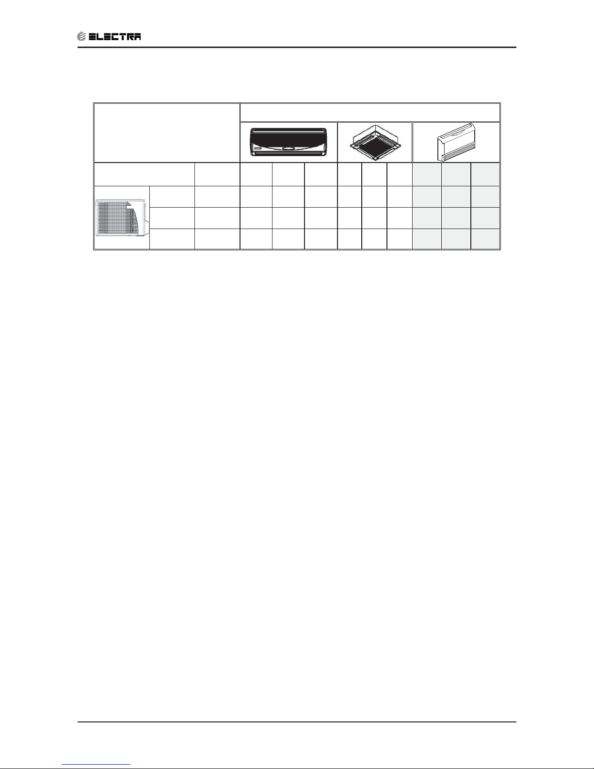
1.9 Matching Table
1.9.1 R410A
OUTDOOR UNITS
INDOOR UNITS
MODEL REFRIGER. WNG25 WNG35 WNG50 K25 K35 K50 PXD25 PXD35 PXD50
ONG25 DCI R410A √ √ √
ONG35 DCI R410A √ √ √
ONG50 DCI R410A √ √ √
The above table lists outdoor units and PXD DCI indoor units which can be matched together.
In addition the listed outdoor units can be matched with other types of indoor units such as
cassettes and wall mounted.
For further information please refer to the relevant Service Manual.
Page 7
2-1
PRODUCT DATA SHEET
Revision Y05-01Service Manual - PXD DCI
2. PRODUCT DATA SHEET
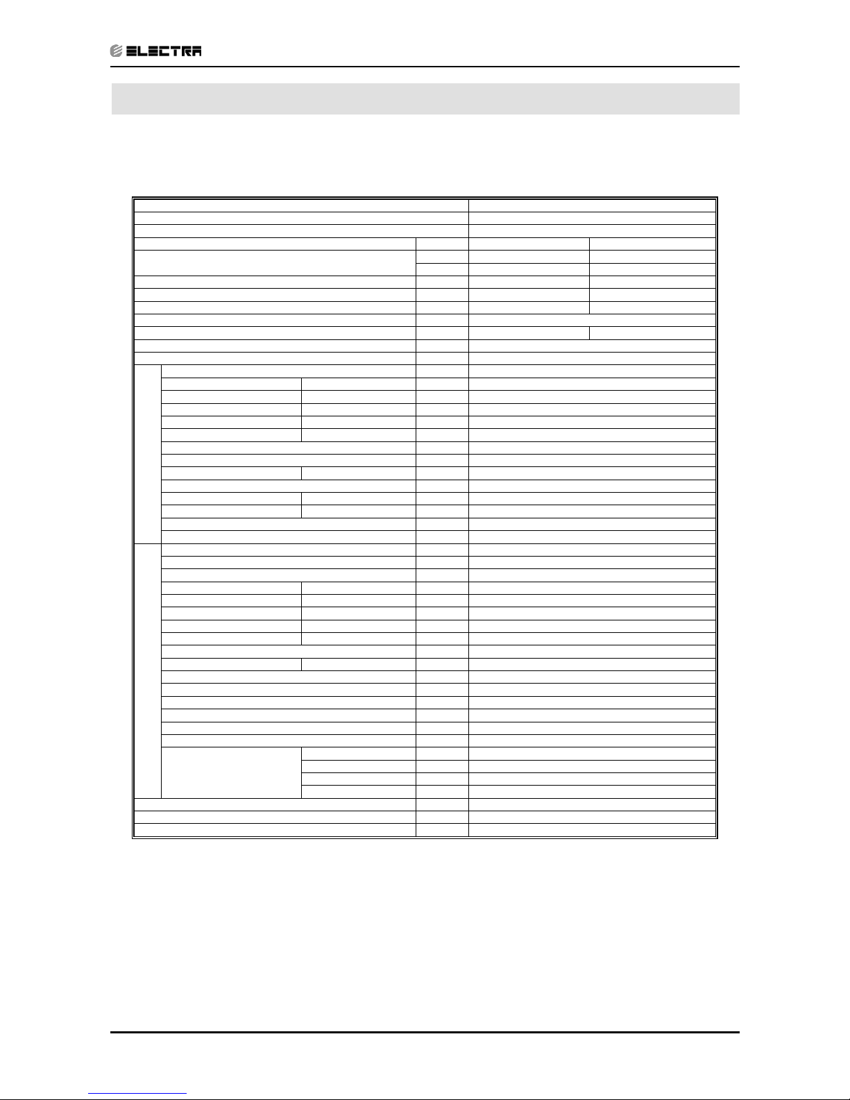
2.1 PXD 25 DCI R410A
Model Indoor Unit PXD 25 DCI
Model Outdoor Unit ONG-25 DCI
Installation Method of Pipe Flared
Characteristics Units Cooling Heating
Btu/hr 8530(4780~12280) 10920(5120~15350)
Capacity
(1)
kW 2.5(1.4-3.6) 3.2(1.5~4.5)
Power input
(1)
kW 0.62(0.42-1.1) 0.93(0.4~1.6)
EER (Cooling) or COP(Heating)
(1)
W/W 4.03 3.41
Energy efficiency class A B
Power supply V/Ph/Hz 220-240V/Single/50Hz
Rated current A 2.7 4.1
Starting current A 10.5
Circuit breaker rating A 35
Fan type & quantity Centrifugal x 2
Fan speeds H/M/L RPM 760/670/500
Air flow
(2)
H/M/L m3/hr 400/350/300
External static pressure Min-Max Pa 0
Sound power level
(3)
H/M/L dB(A) 50/49/47
Sound pressure level
(4
) H/M/L dB(A) 39/37/35
Moisture removal l/hr 1
Condenstate drain tube I.D mm 16
Dimensions WxDxH mm 820*190*630
Weight kg 21
Package dimensions WxDxH mm 890*280*710
Package weight kg 25
Units per pallet units 14units per pallet
INDOOR
Units stacking units 7 levels
Refrigerant control EEV
Compressor type,model Single Rotary,DC Inverter,Panasonic 5RS102XAB
Fan type & quantity Propeller(direct) x 1
Fan speeds H/L RPM 830
Air flow H/L m3/hr 1780
Sound power level H/L dB(A) 61
Sound pressure level
(4)
H/L dB(A) 51
Dimensions WxDxH mm 795*290*610
Weight kg 38
Package dimensions WxDxH mm 945*395*655
Packaged weight kg 42
Units per pallet Units 9
Stacking height units 3 levels
Refrigerant type R410A
Refrigerant chargless distance kg/m 1.10kg/7.5m
Additional charge per 1 meter g/m No Need
Liquid line In.(mm) 1/4"(6.35)
Suction line In.(mm) 3/8"(9.53)
Max.tubing length m. Max.20
OUTDOOR
Connections between units
Max.height difference m. Max.10
Operation control type Remote control
Heating elements (Option) kW
Others
(1) Rating conditions in accordance with ISO 5151 and ISO 13253 (for ducted units) and EN 14511.
(2) Airflow in ducted units; at nominal external static pressure.
(3) Sound power in ducted units is measured at air discharge.
(4) Sound pressure level measured at 1 meter distance from unit.
Page 8

2-2
PRODUCT DATA SHEET
Revision Y05-01 Service Manual - PXD DCI
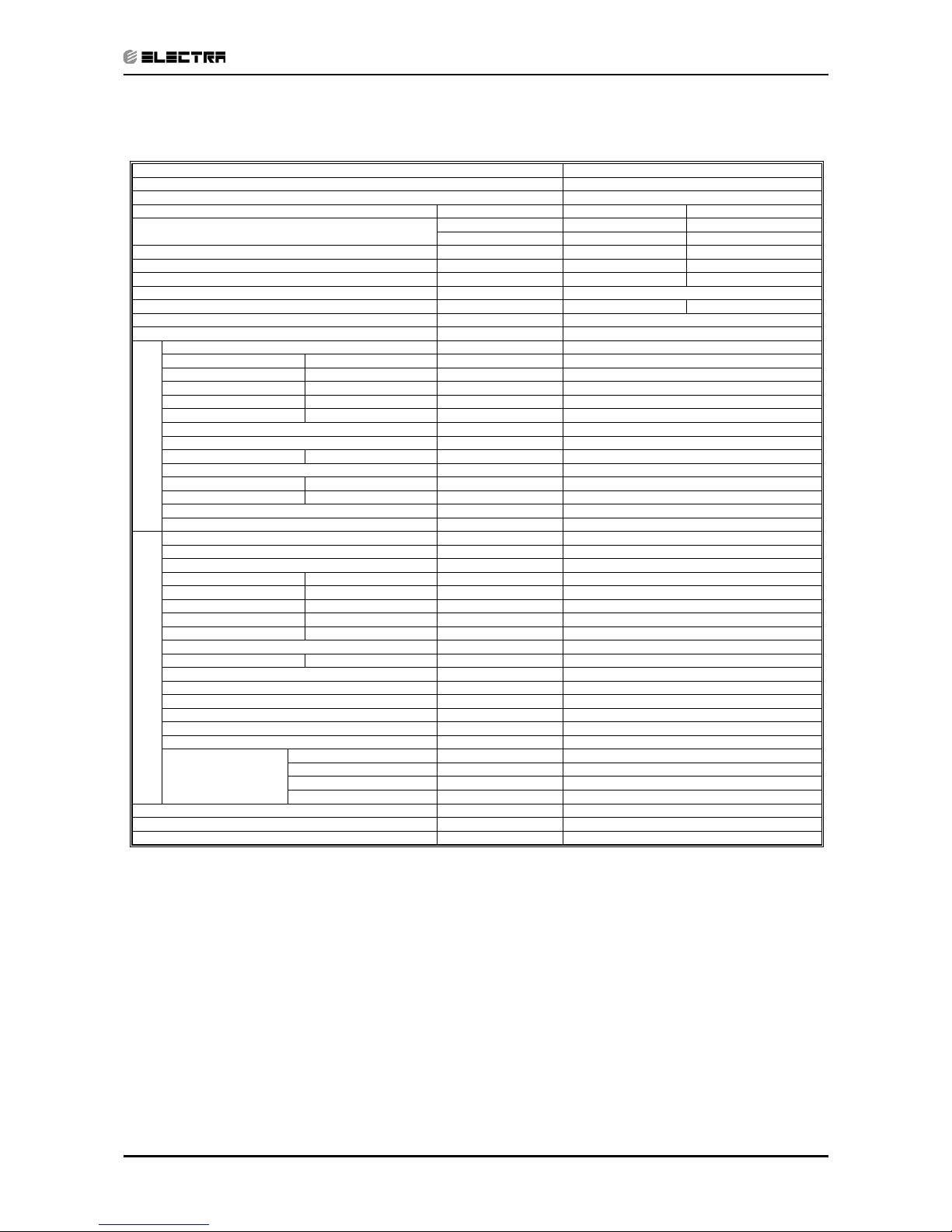
2.2 PXD 35 DCI R410A
Model Indoor Unit PXD 35 DCI
Model Outdoor Unit ONG-DCI 35
Installation Method of Pipe Flared
Characteristics Units Cooling Heating
Btu/hr 11940(5120~15010) 14330(5120~17060)
Capacity
(1)
kW 3.5(1.5-4.4) 4.2(1.5~5.0)
Power input
(1
) kW 0.98(0.46-1.3) 1.31(0.35~1.58)
EER (Cooling) or COP(Heating)
(1)
W/W 3.57 3.21
Energy efficiency class A C
Power supply V/Ph/Hz 220-240V/Single/50Hz
Rated current A 4.3 5.7
Starting current A 10.5
Circuit breaker rating A 35
Fan type & quantity Centrifugal x 2
Fan speeds H/M/L RPM 830/760/500
Air flow
(2)
H/M/L m3/hr 450/400/300
External static pressure Min-Max Pa 0
Sound power level
(3)
H/M/L dB(A) 56/53/51
Sound pressure level
(4)
H/M/L dB(A) 45/41/38
Moisture removal l/hr 1.5
Condenstate drain tube I.D mm 16
Dimensions WxDxH mm 820*190*630
Weight kg 22
Package dimensions WxDxH mm 890*280*710
Package weight kg 26
Units per pallet units 14units per pallet
INDOOR
Units stacking units 7 levels
Refrigerant control EEV
Compressor type,model Single Rotary,DC Inverter,Panasonic 5RS102XAB
Fan type & quantity Propeller(direct) x 1
Fan speeds H/L RPM 830
Air flow H/L m3/hr 1780
Sound power level H/L dB(A) 62
Sound pressure level
(4)
H/L dB(A) 52
Dimensions WxDxH mm 795*290*610
Weight kg 38.5
Package dimensions WxDxH mm 945*395*655
Packaged weight kg 42.5
Units per pallet Units 9
Stacking height units 3 levels
Refrigerant type R410A
Refrigerant chargless distance kg/m 1.20kg/7.5m
Additional charge per 1 meter g/m No Need
Liquid line In.(mm) 1/4"(6.35)
Suction line In.(mm) 3/8"(9.53)
Max.tubing length m. Max.20
OUTDOOR
Connections
between units
Max.height difference m. Max.10
Operation control type Remote control
Heating elements (Option) kW
Others
(1) Rating conditions in accordance with ISO 5151 and ISO 13253 (for ducted units) and EN 14511.
(2) Airflow in ducted units; at nominal external static pressure.
(3) Sound power in ducted units is measured at air discharge.
(4) Sound pressure level measured at 1 meter distance from unit.
Page 9
2-3
PRODUCT DATA SHEET
Revision Y05-01Service Manual - PXD DCI
Model Indoor Unit PXD 50 DCI
Model Outdoor Unit ONG-DCI 50
Installation Method of Pipe Flared
Characteristics Units Cooling Heating
Btu/hr 17000(5120-20460) 20460(5120-24550)
Capacity
(1)
kW 5.0(1.5-6.0) 5.8(1.5~7.2)
Power input
(1)
kW 1.65(0.5-2.1) 1.69(0.45-2.1)
EER (Cooling) or COP(Heating)
(1)
W/W 3.03 3.43
Energy efficiency class B B
Power supply V/Ph/Hz 220-240V/Single/50Hz
Rated current A 7.2 7.7
Starting current A 10.5
Circuit breaker rating A 35
Fan type & quantity Centrifugal x 2
Fan speeds H/M/L RPM 1050/950/700
Air flow
(2)
H/M/L m3/hr 870/750/600
External static pressure Min-Max Pa 0
Sound power level
(3)
H/M/L dB(A) 65/60/56
Sound pressure level
(4)
H/M/L dB(A) 51/48/45
Moisture removal l/hr 2
Condenstate drain tube I.D mm 16
Dimensions WxDxH mm 1200*190*630
Weight kg 30
Package dimensions WxDxH mm 1270*280*710
Package weight kg 35
Units per pallet units 7units per pallet
INDOOR
Units stacking units 7 levels
Refrigerant control EEV
Compressor type,model Single Rotary,DCI, Panasonic 5CS130XCC03
Fan type & quantity Propeller(direct) x 1
Fan speeds H/L RPM 920
Air flow H/L m3/hr 2160
Sound power level H/L dB(A) 63
Sound pressure leve
l(4)
H/L dB(A) 53
Dimensions WxDxH mm 795*290*610
Weight kg 39
Package dimensions WxDxH mm 945*395*655
Packaged weight kg 43
Units per pallet Units 9
Stacking height units 3 levels
Refrigerant type R410A
Refrigerant chargless distance kg/m 1.50kg/7.5m
Additional charge per 1 meter g/m No Need
Liquid line In.(mm) 1/4"(6.35)
Suction line In.(mm) 1/2"(12.7)
Max.tubing length m. Max.30
OUTDOOR
Connections between
units
Max.height difference m. Max.10
Operation control type Remote control
Heating elements (Option) kW
Others
(1) Rating conditions in accordance with ISO 5151 and ISO 13253 (for ducted units) and EN 14511.
(2) Airflow in ducted units; at nominal external static pressure.
(3) Sound power in ducted units is measured at air discharge.
(4) Sound pressure level measured at 1 meter distance from unit.
Scroll
Page 10
3-1
RATING CONDITIONS
Revision Y05-01Service Manual - PXD DCI
3. RATING CONDITIONS
Standard conditions in accordance with ISO 5151, ISO 13253 (for ducted units)
and EN 14511.
Cooling:
Indoor: 27oC DB 19oC WB
Outdoor: 35 oC DB
Heating:
Indoor: 20oC DB
Outdoor: 7oC DB 6oC WB
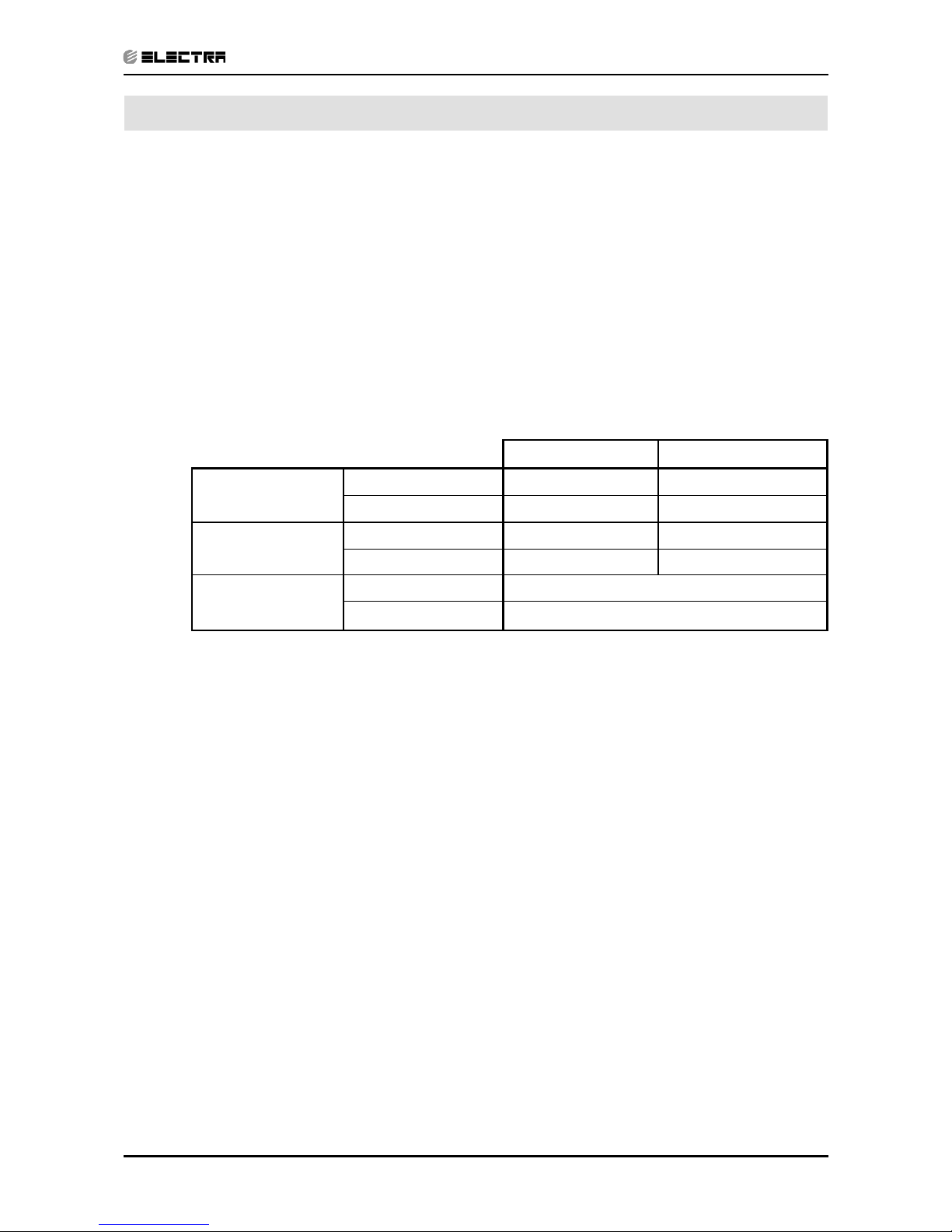
3.1 Operating Limits
R410A
Indoor Outdoor
Cooling
Upper limit 32
o
C DB 23oC WB 46oC DB
Lower limit 21
o
C DB 15oC WB -10oC DB
Heating
Upper limit 27
o
C DB 24oC DB 18oC WB
Lower limit 10oC DB -15oC DB -16oC WB
Voltage
1PH 198 – 264 V
3PH N/A
Page 11
4-1
OUTLINE DIMENSIONS
Revision Y05-01Service Manual - PXD DCI
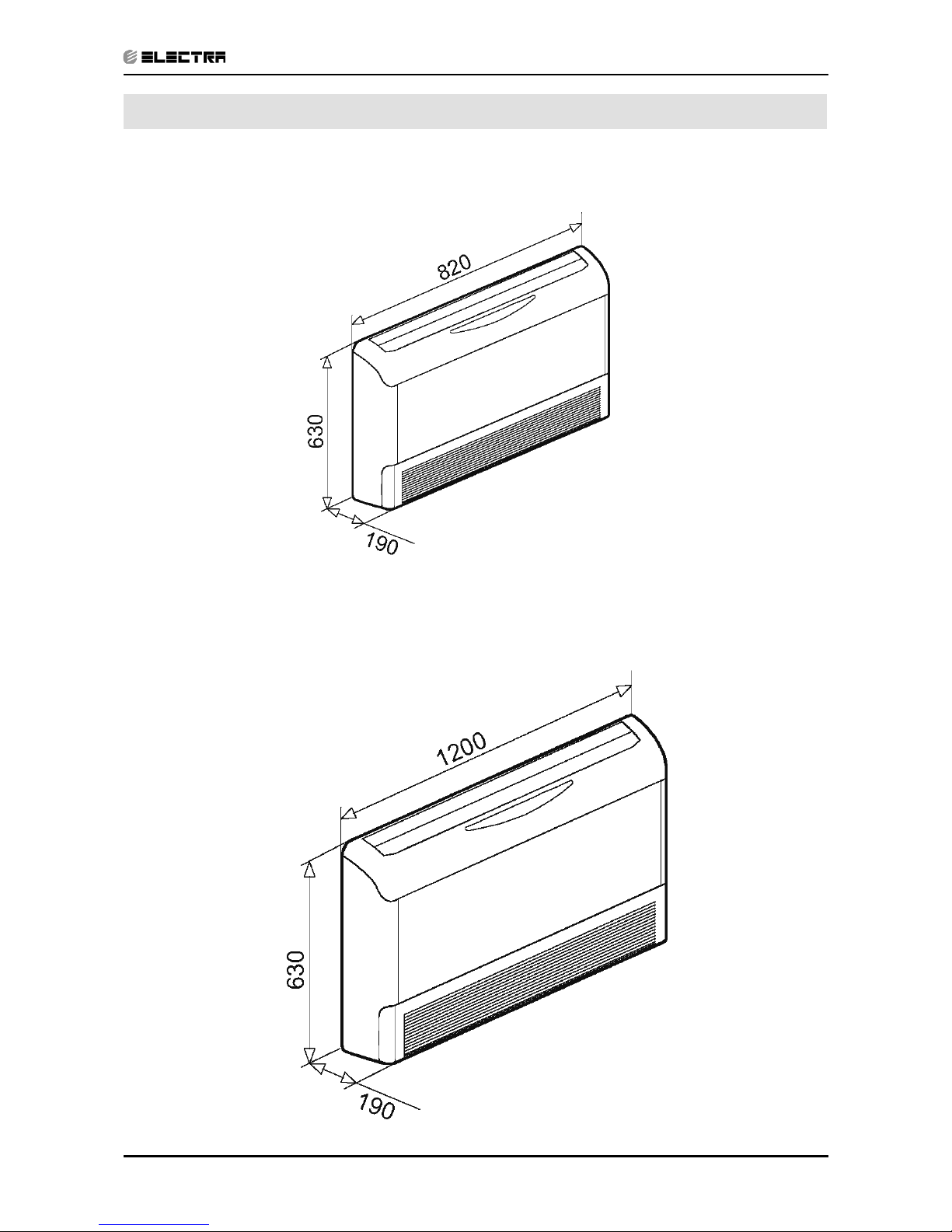
4. OUTLINE DIMENSIONS
4.1 Indoor Unit: PXD 25, 35, DCI
4.2 Indoor Unit: PXD 50 DCI
Page 12
4-2
OUTLINE DIMENSIONS
Revision Y05-01 Service Manual - PXD DCI
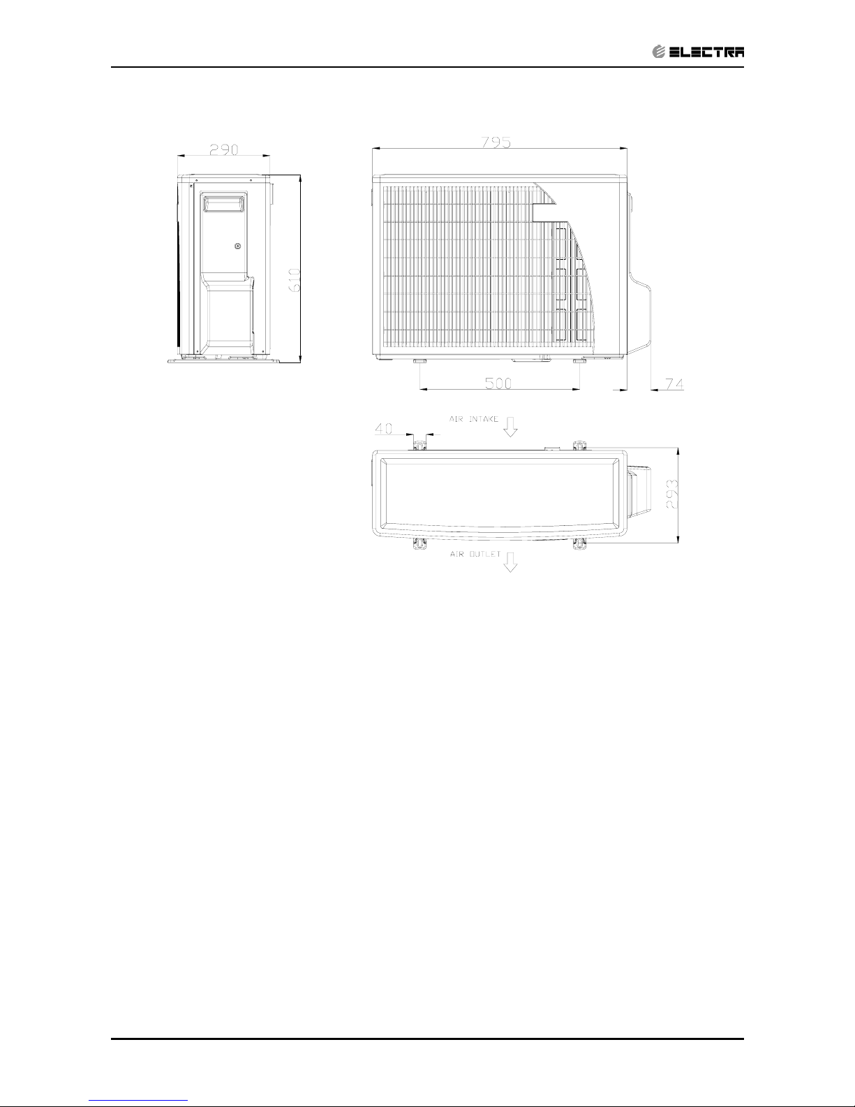
4.3 Outdoor Unit: ONG 25, 35, 50 DCI
Page 13

5-1
PERFORMANCE DATA & PRESSURE CURVES
Revision Y05-01Service Manual - PXD DCI
5. PERFORMANCE DATA
5,1 PXD25 DCI
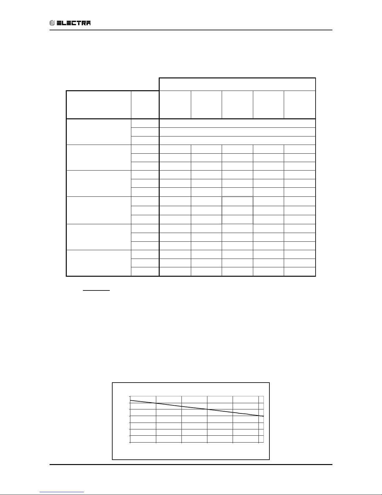
5.1.1 Cooling Capacity (kW) – Run Mode
230[V] : Indoor Fan at High Speed.
ID COIL ENTERING AIR DB/WB TEMPERATURE [oC]
OU COIL
ENTERING AIR DB
TEMPERATURE
[oC]
DATA
22/15 24/17 27/19 29/21 32/23
-10 - 20
(protection range)
TC 80 - 110 % of nominal
SC 80 - 105 % of nominal
PI 25 - 50 % of nominal
25
TC 2.42 2.57 2.73 2.89 3.05
SC 2.09 2.13 2.18 2.22 2.26
PI 0.49 0.50 0.51 0.52 0.52
30
TC 2.30 2.46 2.62 2.77 2.93
SC 2.04 2.08 2.12 2.17 2.21
PI 0.54 0.55
0.56
0.57 0.58
35
TC 2.18 2.34
2.50
2.66 2.82
SC 1.98 2.03 2.07 2.11 2.16
PI 0.60 0.61
0.62
0.63 0.64
40
TC 2.07 2.23
2.38
2.54 2.70
SC 1.93 1.97 2.02 2.06 2.10
PI 0.66 0.67 0.68 0.69 0.70
46
TC 1.93 2.09 2.24 2.40 2.56
SC 1.87 1.91 1.95 2.00 2.04
PI 0.73 0.74 0.75 0.75 0.76
LEGEND
TC – Total Cooling Capacity, kW
SC – Sensible Capacity, kW
PI – Power Input, kW
WB – Wet Bulb Temp., (oC)
DB – Dry Bulb Temp., (oC)
ID – Indoor
OU – Outdoor
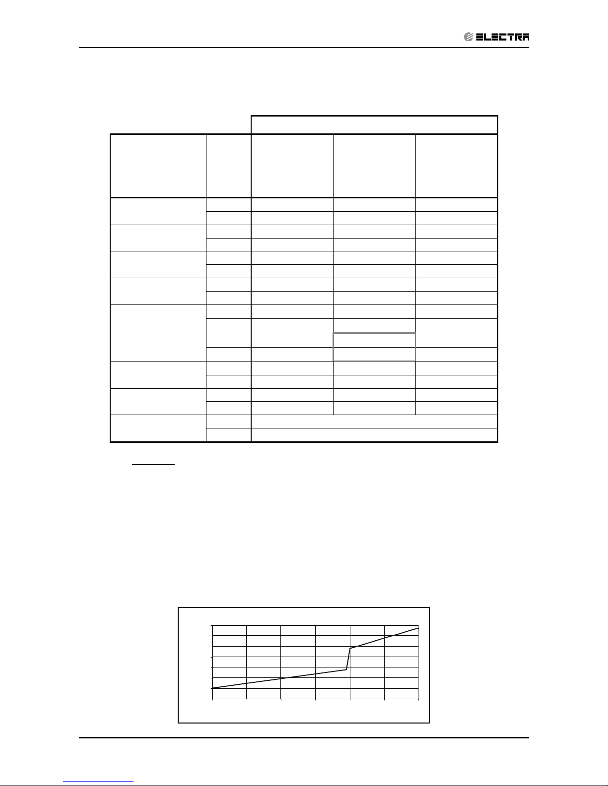
5.1.2 Capacity Correction Factors
Cooling Capac ity Ratio V s. Out door Te mpe rature
0.50
0.60
0.70
0.80
0.90
1.00
1.10
1.20
20 25 30 35 40 45
Outdoor Temperature [ºC]
Capacity Rati
o
Page 14
5-2
PERFORMANCE DATA & PRESSURE CURVES
Revision Y05-01 Service Manual - PXD DCI
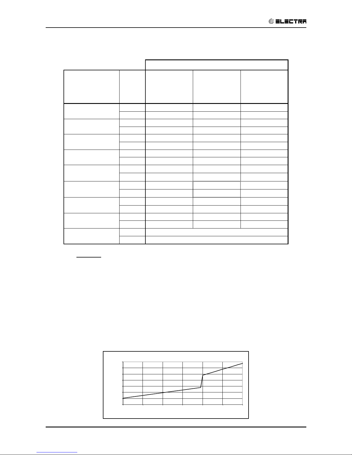
5.1.3 Heating Capacity (kW) - Run Mode
230[V] : Indoor Fan at High Speed.
ID COIL ENTERING AIR DB TEMPERATURE [oC]
OU COIL
ENTERING
AIR DB/WB
TEMPERATURE
[oC]
DATA 15 20 25
-15/-16
TC 2.04 1.89 1.75
PI 0.56 0.61 0.67
-10/-12
TC 2.27 2.12 1.98
PI 0.67 0.73 0.79
-7/-8
TC 2.44 2.30 2.16
PI 0.76 0.82 0.87
-1/-2
TC 2.53 2.38 2.24
PI 0.80 0.86 0.92
2/1
TC 2.58 2.44 2.30
PI 0.83
0.89
0.94
7/6
TC 3.34
3.20
3.06
PI 0.87
0.93
0.99
10/9
TC 3.53
3.38
3.24
PI 0.93 0.98 1.04
15/12
TC 3.71 3.57 3.43
PI 0.98 1.03 1.09
15-24
TC 85 - 105 % of nominal
(Protection Range)
PI 80 - 120 % of nominal
LEGEND
TC – Total Heating Capacity, kW
PI – Power Input, kW
WB – Wet Bulb Temp., (
o
C)
DB – Dry Bulb Temp., (
o
C)
ID – Indoor
OU – Outdoor
5.1.4 Capacity Correction Factors
Heating Ca pacity Ratio Vs . Outdoor Tempe rature
0.50
0.60
0.70
0.80
0.90
1.00
1.10
1.20
-15 -10 -5 0 5 10 15
Outdoor WB Tem pera ture [deg C]
Capaci ty Rati on
Page 15

5-3
PERFORMANCE DATA & PRESSURE CURVES
Revision Y05-01Service Manual - PXD DCI
5.2 PXD35 DCI
5.2.1 Cooling Capacity (kW) - Run Mode
230[V] : Indoor Fan at High Speed.
ID COIL ENTERING AIR DB/WB TEMPERATURE [oC]
OU COIL
ENTERING AIR DB
TEMPERATURE [oC]
DATA
22/15 24/17 27/19 29/21 32/23
-10 - 20
(protection range)
TC 80 - 110 % of nominal
SC 80 - 105 % of nominal
PI 25 - 50 % of nominal
25
TC 3.38 3.60 3.83 4.05 4.27
SC 2.65 2.70 2.75 2.81 2.86
PI 0.77 0.78 0.80 0.81 0.83
30
TC 3.22 3.44 3.66 3.88 4.11
SC 2.58 2.63 2.69 2.74 2.79
PI 0.86 0.88
0.89
0.90 0.92
35
TC 3.06 3.28
3.50
3.72 3.94
SC 2.51 2.57 2.62 2.67 2.73
PI 0.95 0.97
0.98
0.99 1.01
40
TC 2.89 3.12
3.34
3.56 3.78
SC 2.45 2.50 2.55 2.61 2.66
PI 1.04 1.06 1.07 1.08 1.10
46
TC 2.70 2.92 3.14 3.36 3.58
SC 2.37 2.42 2.47 2.53 2.58
PI 1.15 1.16 1.18 1.19 1.21
LEGEND
TC – Total Cooling Capacity, kW
SC – Sensible Capacity, kW
PI – Power Input, kW
WB – Wet Bulb Temp., (oC)
DB – Dry Bulb Temp., (oC)
ID – Indoor
OU – Outdoor
5.2.2 Capacity Correction Factor
Cooling Capac ity Ratio V s. Out door Te mpe rature
0.50
0.60
0.70
0.80
0.90
1.00
1.10
1.20
20 25 30 35 40 45
Outdoor Temperature [ºC]
Capacity Rati
o
Page 16

5-4
PERFORMANCE DATA & PRESSURE CURVES
Revision Y05-01 Service Manual - PXD DCI
5.2.3 Heating Capacity (kW) - Run Mode
230[V] : Indoor Fan at High Speed.
ID COIL ENTERING AIR DB TEMPERATURE [oC]
OU COIL
ENTERING
AIR DB/WB
TEMPERATURE
[oC]
DATA 15 20 25
-15/-16
TC 2.67 2.49 2.30
PI 0.79 0.87 0.95
-10/-12
TC 2.98 2.79 2.60
PI 0.95 1.03 1.11
-7/-8
TC 3.20 3.02 2.83
PI 1.07 1.15 1.23
-1/-2
TC 3.32 3.13 2.94
PI 1.13 1.21 1.29
2/1
TC 3.39 3.20 3.02
PI 1.17
1.25
1.33
7/6
TC 4.39
4.20
4.01
PI 1.23
1.31
1.39
10/9
TC 4.63
4.44
4.26
PI 1.30 1.38 1.46
15/12
TC 4.87 4.68 4.50
PI 1.38 1.46 1.54
15-24
TC 85 - 105 % of nominal
(Protection Range)
PI 80 - 120 % of nominal
LEGEND
TC – Total Heating Capacity, kW
PI – Power Input, kW
WB – Wet Bulb Temp., (oC)
DB – Dry Bulb Temp., (oC)
ID – Indoor
OU – Outdoor
5.2.4 Capacity Correction Factors
Heating Ca pacity Ratio Vs . Outdoor Tempe rature
0.50
0.60
0.70
0.80
0.90
1.00
1.10
1.20
-15 -10 -5 0 5 10 15
Outdoor WB Tem pera ture [deg C]
Capacity Ration
Page 17
5-5
PERFORMANCE DATA & PRESSURE CURVES
Revision Y05-01Service Manual - PXD DCI
5.3 PXD50 DCI
5.3.1 Cooling Capacity (kW) - Run Mode
230[V] : Indoor Fan at High Speed.
ID COIL ENTERING AIR DB/WB TEMPERATURE [oC]
OU COIL
ENTERING AIR DB
TEMPERATURE [oC]
DATA
22/15 24/17 27/19 29/21 32/23
-10 - 20
(protection range)
TC 80 - 110 % of nominal
SC 80 - 105 % of nominal
PI 25 - 50 % of nominal
25
TC 4.93 5.22 5.51 5.80 6.09
SC 3.35 3.40 3.45 3.50 3.55
PI 1.25 1.28 1.30 1.33 1.36
30
TC 4.67 4.96 5.25 5.54 5.83
SC 3.22 3.27 3.32 3.37 3.42
PI 1.42 1.45
1.48
1.50 1.53
35
TC 4.42 4.71
5.00
5.29 5.58
SC 3.09 3.14 3.19 3.24 3.29
PI 1.59 1.62
1.65
1.68 1.71
40
TC 4.17 4.46
4.75
5.04 5.33
SC 2.96 3.01 3.06 3.11 3.16
PI 1.77 1.80 1.82 1.85 1.88
46
TC 3.86 4.15 4.44 4.73 5.02
SC 2.80 2.85 2.90 2.95 3.00
PI 1.98 2.00 2.03 2.06 2.09
LEGEND
TC – Total Cooling Capacity, kW
SC – Sensible Capacity, kW
PI – Power Input, kW
WB – Wet Bulb Temp., (oC)
DB – Dry Bulb Temp., (oC)
ID – Indoor
OU – Outdoor
5.3.2 Capacity Correction Factors
Cooling Capac ity Ratio V s. Out door Te mpe rature
0.50
0.60
0.70
0.80
0.90
1.00
1.10
1.20
20 25 30 35 40 45
Outdoor Temperature [ºC]
Capacity Rati
o
Page 18
5-6
PERFORMANCE DATA & PRESSURE CURVES
Revision Y05-01 Service Manual - PXD DCI
5.3.3 Heating Capacity (kW) - Run Mode
230[V] : Indoor Fan at High Speed.
ID COIL ENTERING AIR DB TEMPERATURE [oC]
OU COIL
ENTERING
AIR DB/WB
TEMPERATURE
[oC]
DATA 15 20 25
-15/-16
TC 2.64 2.26 1.88
PI 1.18 1.27 1.35
-10/-12
TC 3.48 3.10 2.72
PI 1.34 1.42 1.50
-7/-8
TC 4.12 3.74 3.36
PI 1.45 1.54 1.62
-1/-2
TC 4.43 4.05 3.67
PI 1.51 1.59 1.68
2/1
TC 4.65 4.27 3.89
PI 1.55
1.63
1.72
7/6
TC 6.18
5.80
5.42
PI 1.61
1.69
1.77
10/9
TC 6.50
6.12
5.74
PI 1.64 1.72 1.81
15/12
TC 6.82 6.44 6.06
PI 1.67 1.75 1.84
15-24
TC 85 - 105 % of nominal
(Protection Range)
PI 80 - 120 % of nominal
LEGEND
TC – Total Heating Capacity, kW
PI – Power Input, kW
WB – Wet Bulb Temp., (
o
C)
DB – Dry Bulb Temp., (
o
C)
ID – Indoor
OU – Outdoor
5.3.4 Capacity Correction Factors
Hea ting Cap acit y Rat io Vs. O utdo or Tem pera ture
0.50
0.60
0.70
0.80
0.90
1.00
1.10
1.20
-15 -10 -5 0 5 10 15
Outdoor WB Tem pera ture [deg C]
Capaci ty Rati on
Page 19
5-7
PERFORMANCE DATA & PRESSURE CURVES
Revision Y05-01Service Manual - PXD DCI
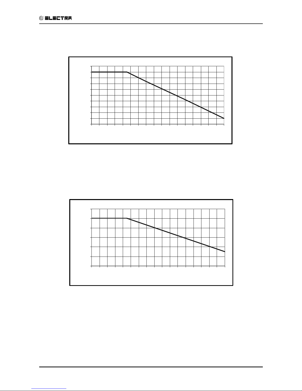
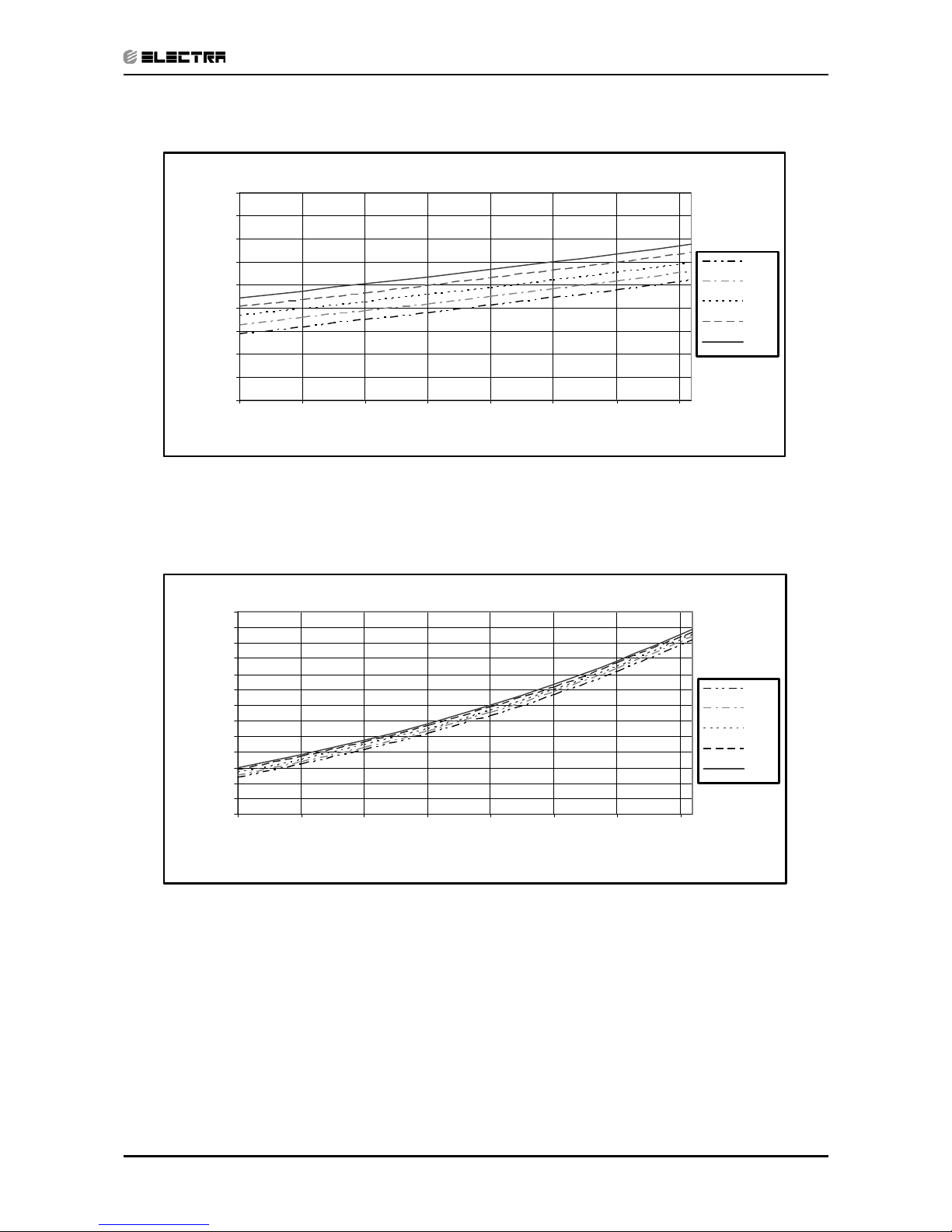
5.4 Capacity Correction Factor Due to Tubing Length
5.4.1 PXD 25/35 DCI :Cooling
5.4.2 Heating
0.91
0.92
0.93
0.94
0.95
0.96
0.97
0.98
0.99
1.00
1.01
3 4 5 6 7 8 9 1011121314151617181920
Tubing Length [m]
Capacity Ratio
0.90
0.92
0.94
0.96
0.98
1.00
1.02
3 4 5 6 7 8 9 1011121314151617181920
Tubing Length [m]
Capacity Ratio
Page 20
5-8
PERFORMANCE DATA & PRESSURE CURVES
Revision Y05-01 Service Manual - PXD DCI
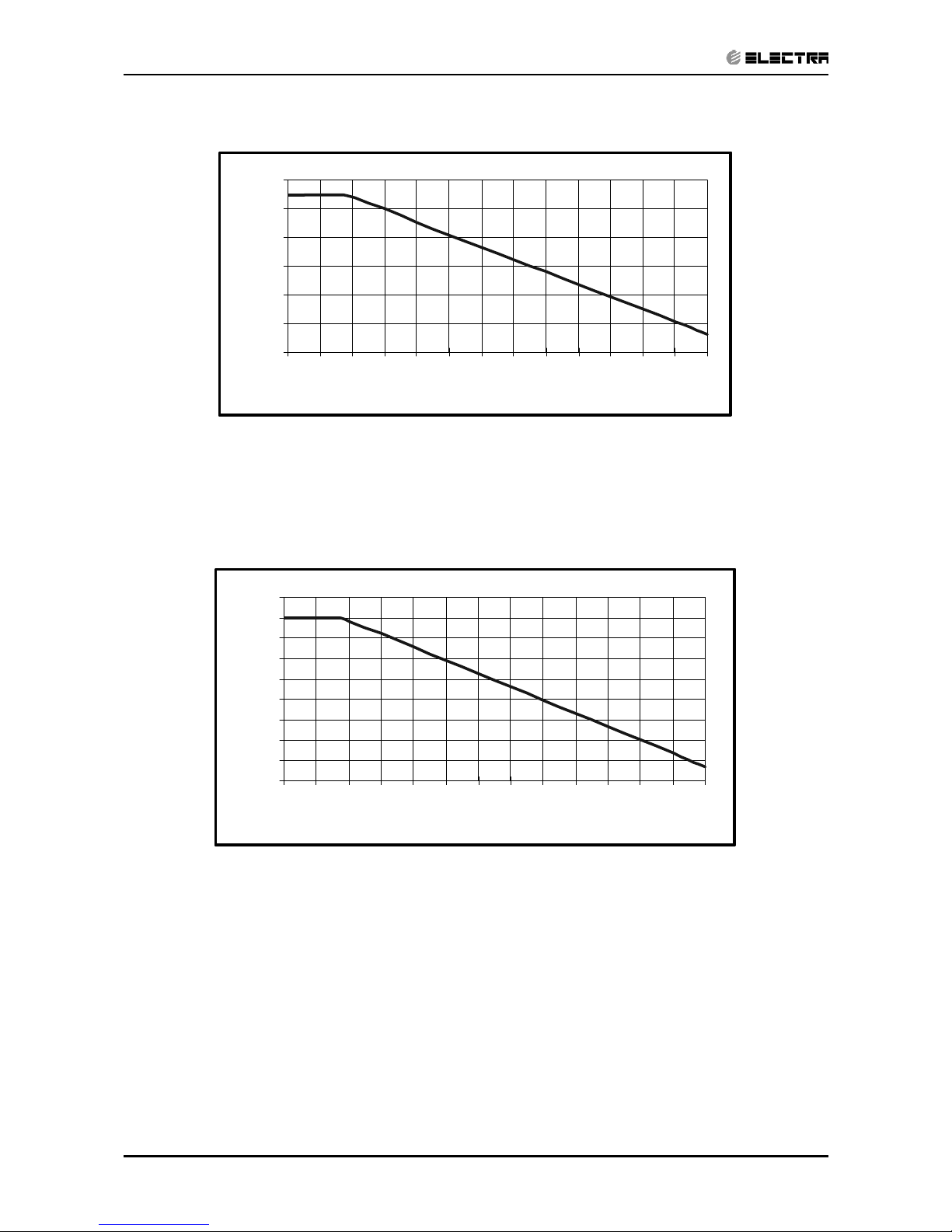
5.4.3 PXD 50 DCI :Cooling
5.4.4 Heating
0.89
0.91
0.93
0.95
0.97
0.99
1.01
4 6 8 1012141618202224262830
Tubing length(m )
Capacity ratio
0.84
0.86
0.88
0.90
0.92
0.94
0.96
0.98
1.00
1.02
4 6 8 101214161820222426 2830
Tubing Length(m)
Capacity ratio
Page 21
5-9
PERFORMANCE DATA & PRESSURE CURVES
Revision Y05-01Service Manual - PXD DCI
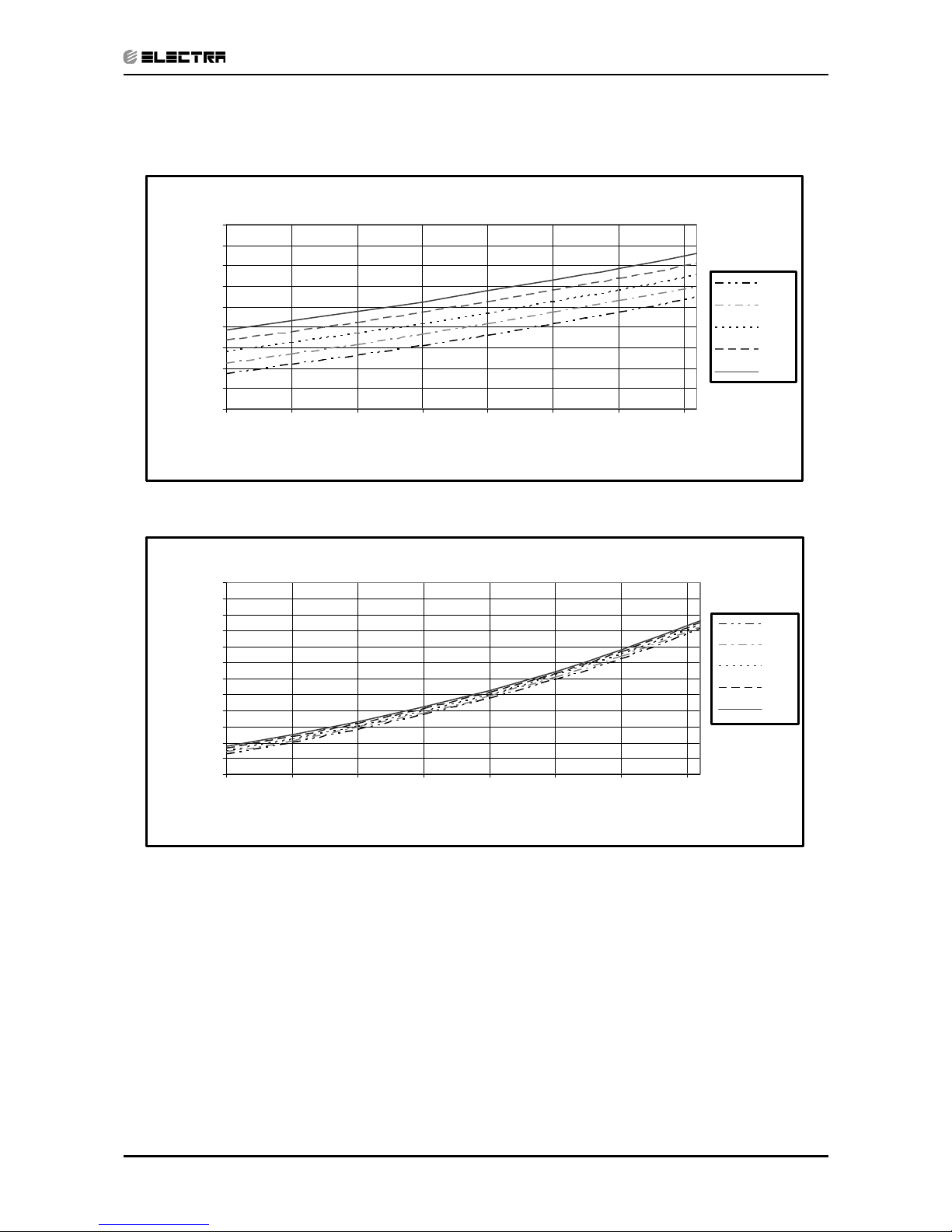
5.5 Pressure Curves
5.5.1 Model: PXD 25 DCI Cooling – Test Mode
Suction Pressure Vs.Outdoor Temp.
500
600
700
800
900
1000
1100
1200
1300
1400
10 15 20 25 30 35 40 45
Outdoor DB Tempe rature[ºC ]
Suction Pressure [kPa]
22/15
24/17
27/19
29/21
32/23
Indoor
DB/WB
Discharge Pressure Vs. Outdoor Temp.
1000
1250
1500
1750
2000
2250
2500
2750
3000
3250
3500
3750
4000
10 15 20 25 30 35 40 45
Outdoor DB Temperature[ºC ]
Discharge Pressure [kPa]
22/15
24/17
27/19
29/21
32/23
Indoor
DB/W B
Page 22
5-10
PERFORMANCE DATA & PRESSURE CURVES
Revision Y05-01 Service Manual - PXD DCI
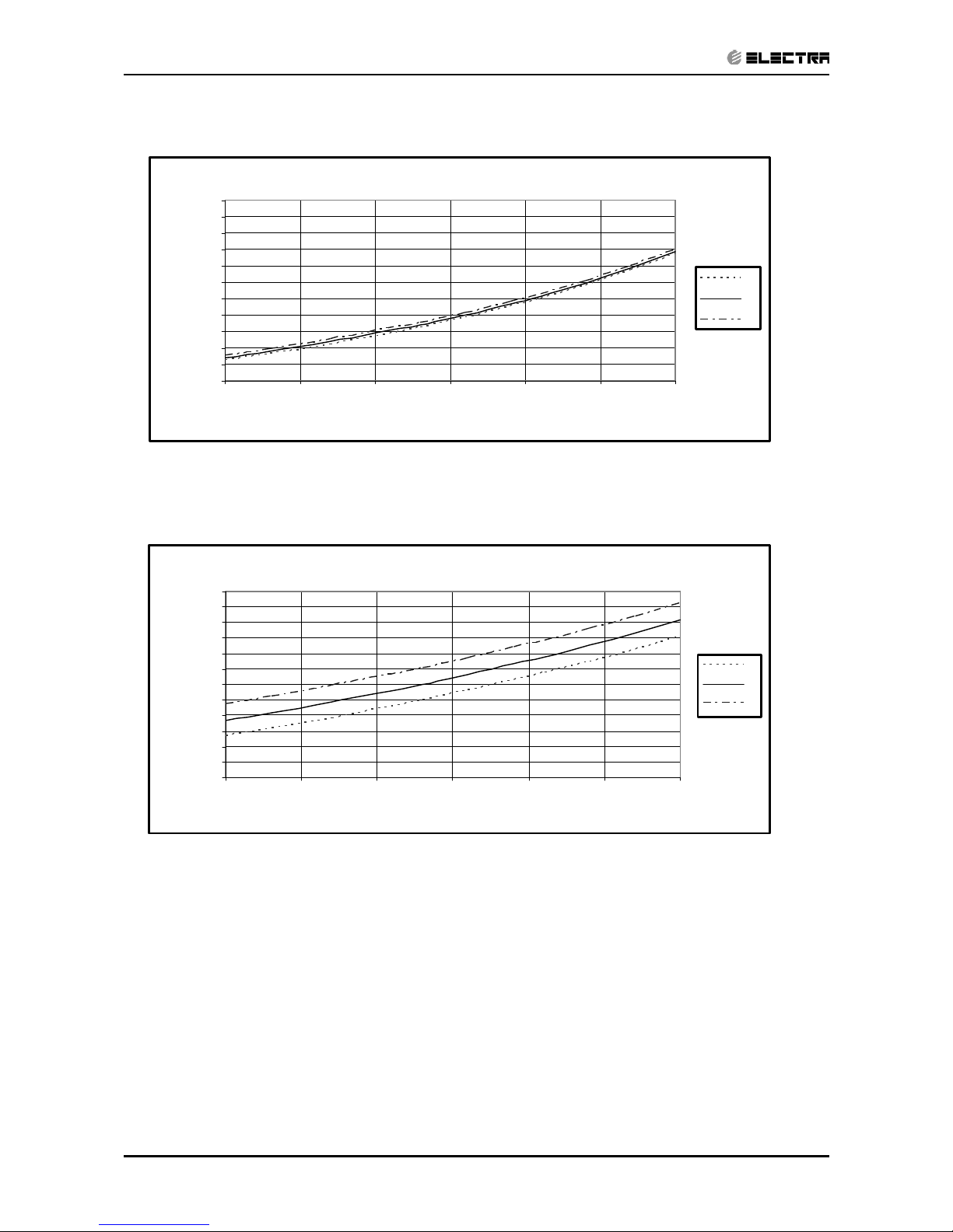
5.5.2 Heating – Test Mode
Suction Pressure Vs.Outdoor Temp.
200
300
400
500
600
700
800
900
1000
1100
1200
1300
-15 -10 -5 0 5 10 15
Outdoor WB Temperature [ºC]
Suction Pressure [kPa]
15
20
25
Discharge Pressure Vs. Outdoor Temp.
1000
1250
1500
1750
2000
2250
2500
2750
3000
3250
3500
3750
4000
-15 -10 -5 0 5 10 15
Outdoor WB Temperature [ºC]
Discharge Pressure [kPa]
15
20
25
Indoor DB
Page 23
5-11
PERFORMANCE DATA & PRESSURE CURVES
Revision Y05-01Service Manual - PXD DCI
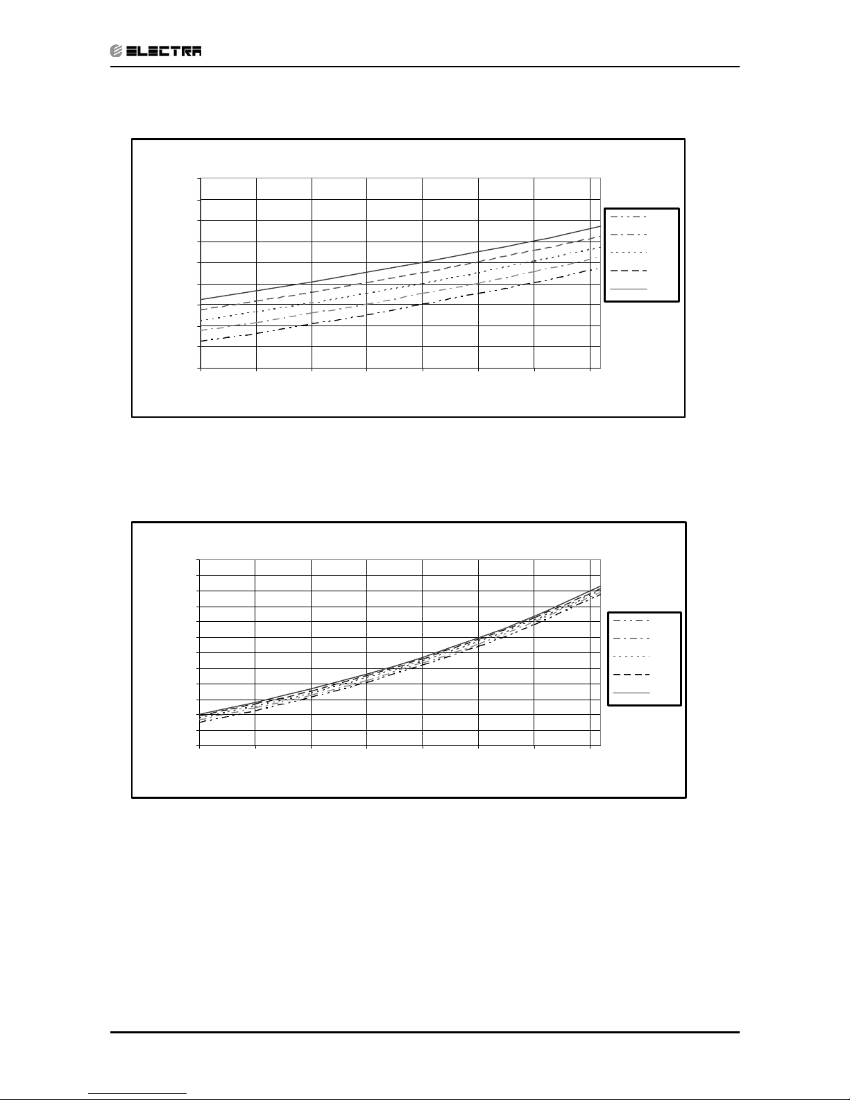
5.5.3 Model: PXD 35 DCI Cooling – Test Mode
Suction Pressure VS.Outdoor Temp.
500
600
700
800
900
1000
1100
1200
1300
1400
10 15 20 25 30 35 40 45
Outdoor DB Tempe rature[ºC ]
Suction Pressure [kPa]
22/15
24/17
27/19
29/21
32/23
Indoor
DB/W B
Discharge Pressure VS. Outdoor Temp.
1000
1250
1500
1750
2000
2250
2500
2750
3000
3250
3500
3750
4000
10 15 20 25 30 35 40 45
Outdoor DB Tempe rature[ºC ]
Discharge Pressure [kPa]
22/15
24/17
27/19
29/21
32/23
Indoor
DB/W B
Page 24
5-12
PERFORMANCE DATA & PRESSURE CURVES
Revision Y05-01 Service Manual - PXD DCI
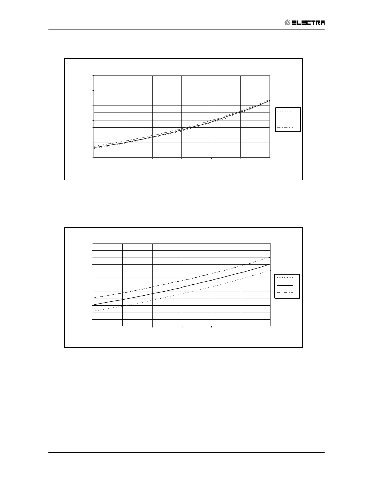
5.5.4 Heating – Test Mode
Suction Pressure VS.Outdoor Temp.
200
300
400
500
600
700
800
900
1000
1100
1200
1300
-15 -10 -5 0 5 10 15
Outdoor WB Temperature [ºC]
Suction Pressure [kPa]
15
20
25
Discharge Pressure VS. Outdoor Temp.
1000
1250
1500
1750
2000
2250
2500
2750
3000
3250
3500
3750
4000
-15 -10 -5 0 5 10 15
Outdoor WB Temperature [ºC]
Discharge Pressure [kPa]
15
20
25
Indoor DB
Page 25
5-13
PERFORMANCE DATA & PRESSURE CURVES
Revision Y05-01Service Manual - PXD DCI
5.5.5 Model: PXD 50 DCI Cooling – Test Mode
Suction Pressure VS.Outdoor Temp.
500
600
700
800
900
1000
1100
1200
1300
1400
10 15 20 25 30 35 40 45
Outdoor DB Tempe rature[ºC ]
Suction Pressure [kPa]
22/15
24/17
27/19
29/21
32/23
Indoor
DB/W B
Discharge Pressure VS. Outdoor Temp.
1000
1250
1500
1750
2000
2250
2500
2750
3000
3250
3500
3750
4000
4250
10 15 20 25 30 35 40 45
Outdoor DB Tempe rature[ºC ]
Discharge Pressure [kPa]
22/15
24/17
27/19
29/21
32/23
Indoor
DB/W B
Page 26

5-14
PERFORMANCE DATA & PRESSURE CURVES
Revision Y05-01 Service Manual - PXD DCI
5.5.6 Heating – Test Mode
Suction Pressure VS.Outdoor Temp.
200
300
400
500
600
700
800
900
1000
1100
-15 -10 -5 0 5 10 15
Outdoor WB Temperature [ºC]
Suction Pressure [kPa]
15
20
25
Discharge Pressure VS. Outdoor Temp.
1000
1250
1500
1750
2000
2250
2500
2750
3000
3250
3500
3750
4000
-15 -10 -5 0 5 10 15
Outdoor WB Temperature [ºC]
Discharge P ressure [kPa]
15
20
25
Indoor DB
Page 27

6-1
ELECTRICAL DATA
Revision Y05-01Service Manual - PXD DCI
6. ELECTRICAL DATA
6.1 Single Phase Units
MODEL PXD 25 DCI PXD 35 DCI PXD 50 DCI
Power Supply
To indoor To indoor To indoor
1PH-230V-50Hz 1PH-230V-50Hz 1PH-230V-50Hz
Max Current, A 10 10 12
Inrush Current A 35 35 35
Starting Current A 10.5 10.5 10.5
Circuit Breaker A 16 16 20
Power Supply Wiring No. X
Cross Section mm
2
3x1.5 mm
2
3x1.5 mm
2
3x2.5 mm
2
Interconnecting Cable No. X
Cross Section mm
2
4x1.5 mm
2
4x1.5 mm
2
4x2.5 mm
2
NOTE
Power wiring cord should comply with local lows and electrical
regulations requirements.
Page 28

7-1
WIRING DIAGRAMS
Revision Y05-01Service Manual - PXD DCI
7. WIRING DIAGRAMS
7.1 PXD 25, 35, 50 DCI
Choke coil
Outdoor unit controller PCB
OUTDOOR UNIT CIRCUIT DIAGRAM
COMP
Bla c k
Red
Brow n
P3
U
V
P9
White
W
P11 P13
COM
P10
L
N
N-COM
Red
Black
Blue
OFAN
3 4
P18
1
Base
heater
valve
Reverse
Blue
P14
2
1
P4
2
P1
1 2
V dc
V cc
E ARTH
Red
P16
Oran ge
Blac k
P17
OCT
P19
2
OAT
5 6
FG
V
sp
P22
Blue
Y ellow
P21
1
2
P2
1
SUCTCTT
1
P8P20
1
22
Red
Brown
magnetic ring
EARTH
COM
EMI f ilter PCB
EARTH
P12
Y/G
Y/G
EARTH
NCOM
N-F
L-F
COM
L
3
JP9
1
2
5
4 6
N
FUSE
EEV
4
P7
6
5
231
Y/G
C/5
L/4
N/3
megatool
2
P6
1
4
3
Y/G
Red
Blue
Brown
Display
POWER SUPPLY
Blue
Red
Brown
Y/G
Page 29

8-1
REFRIGERATION DIAGRAMS
Revision Y05-01Service Manual - PXD DCI
8. REFRIGERATION DIAGRAMS
8.1 PXD 25, 35, 50 DCI / ONG3 25, 35, 50 DCI
EEV
EEV
Page 30

9-1
TUBING CONNECTIONS
Revision Y05-01Service Manual - PXD DCI
9. TUBING CONNECTIONS
TUBE (Inch)
TORQUE (Nm)
¼” ⅜” ½” ⅝” ¾”
Flare Nuts 11-13 40-45 60-65 70-75 80-85
Valve Cap 13-20 13-20 18-25 18-25 40-50
Service Port Cap 11-13 11-13 11-13 11-13 11-13
1. Valve Protection Cap-end
2. Refrigerant Valve Port (use Allen wrench to open/close)
3. Valve Protection Cap
4. Refrigerant Valve
5. Service Port Cap
6. Flare Nut
7. Unit Back Side
8. Copper Tube
When the outdoor unit is installed above the indoor unit an oil trap is required every 5m along the suction
line at the lowest point of the riser. Incase the indoor unit is installed above the outdoor, no trap is
required.
Page 31

10-1
CONTROL SYSTEM
Revision Y05-01Service Manual - PXD DCI
10. CONTROL SYSTEM
10.1 General Functions and Rules (for single split models)
The DCI software is fully parametric.
All the model dependent parameters are shown in Blue color and with Italic style
[parameter].
The parameters values are given in the last section of this control logic chapter of the
service manual.
10.2 System Operation Concept
The control function is divided between indoor and outdoor unit controllers.
Indoor unit is the system ‘Master’, requesting the outdoor unit for cooling/heating
capacity supply. The outdoor unit is the system ‘Slave’ and it must supply the
required capacity unless it enters into a protection mode avoiding it from
supplying the requested capacity.
The capacity request is transferred via indoor to outdoor communication, and is
represented by a parameter called ‘NLOAD’. NLOAD is an integer number with
values between 0 and 127, and it represents the heat or cool load felt by the
indoor unit.
10.3 Compressor Frequency Control
10.3.1 NLOAD setting
The NLOAD setting is done by the indoor unit controller, based on a PI control
scheme.
The actual NLOAD to be sent to the outdoor unit controller is based on the
preliminary LOAD calculation, the indoor fan speed, and the power shedding
function.
NLOAD limits as a function of indoor fan speed:
Indoor Fan Speed Maximum NLOAD Cooling Maximum NLOAD Heating
Low
Max NLOADIF1C
127
Medium
Max NLOADIF2C
127
High
Max NLOADIF3C
127
Turbo
Max NLOADIF4C
127
Auto
Max NLOADIF5C
127
NLOAD limits as a function of power shedding:
Mode Power Shedding OFF Power Shedding ON
Cool No limit Nominal Cooling
Heat No limit Nominal Heating
Page 32

10-2
CONTROL SYSTEM
Revision Y05-01 Service Manual - PXD DCI
10.3.2
Target Frequency Setting
The compressor target frequency is a function of the NLOAD number sent from
the indoor controller and the outdoor air temperature.
Basic Target Frequency Setting:
NLOAD Target Frequency
127
Maximum frequency
10 < NLOAD < 127 Interpolated value between minimum and maximum frequency
10
Minimum frequency
0 Compressor is stopped
Target frequency limits as a function of outdoor air temperature (OAT):
OAT Range Cool mode limits Heat mode limits
OAT < 6 No limit
6 OAT < 15
MaxFreqAsOAT1H
15 OAT < 24
MaxFreqAsOATC
24 OAT No limit
MaxFreqAsOAT2H
10.3.3 Frequency Changes Control
Frequency change rate is 1 Hz/sec.
10.3.4
Compressor Starting Control
Frequency
Time
Min 10 Minutes
1
Minute
Step 1
Step 3
1
Minute
Step 2
10.3.5 Minimum On and Off Time
3 minutes
Page 33

10-3
CONTROL SYSTEM
Revision Y05-01Service Manual - PXD DCI
10.4 Indoor Fan Control
10 Indoor fan speeds are determined for each model. 5 speeds for cool/dry/fan
modes and 5 speeds for heat mode.
When user sets the indoor fan speed to a fixed speed (Low/ Medium/ High), unit
will operate constantly at set speed.
When Auto Fan is selected, indoor unit controller can operate in all speeds. The
actual speed is set according to the cool/heat load.
10.4.1
Turbo Speed
The Turbo speed is activated during the first 30 minutes of unit operation when
auto fan speed is selected and under the following conditions:
x Difference between set point and actual room temperature is bigger then 3
degrees.
x Room temperature > 22 for cooling, or < 25 for heating.
10.5 Heating Element Control
Heating element can be started if LOAD > 0.8 * MaximumNLOAD AND Indoor
Coil temperature < 45.
The heating element will be stopped when LOAD < 0.5 * MaximumNLOAD OR if
Indoor Coil temperature > 50.
10.6 Outdoor Fan Control
7 outdoor fan speeds are determined for each model. 3 speeds for cool and dry
modes, and 3 speeds for heat mode, and a very low speed.
Outdoor fan speed is a function of compressor frequency and outdoor air
temperature (OAT).
4 routines for fan control are determined. The control routine selection depends
on operation mode, compressor speed, and outdoor air temperature (OAT) and
heat sink temperature (HST).
Routine Conditions
A
Heating with OAT < 15
0
C
or
Cooling with OAT > 20
0
C, or HST > 500C
or
Faulty OAT
B Cooling with 20
0
C > OAT > 70C
C Cooling with 7
0
C > OAT
D Heating with OAT > 15
0
C
Page 34

10-4
CONTROL SYSTEM
Revision Y05-01 Service Manual - PXD DCI
Outdoor Fan Speed
Compressor Frequency (CF)
Routine A Routine B Routine C Routine D
CF = 0 OFF OFF OFF OFF
10 CF <
OFLowFreq
Low Low Very Low Low
OFLowFreq CF < OFMedFreq
Medium Low Very Low Low
OFMedFreq CF
High Low Low Medium
In cooling mode, the extra rule is as the below:
Change To Higher
OFAN Cool state (*1)
45
50
HST
Change To lower
OFAN Cool state
(*1) If State C, change to B
If State B, change to A
When compressor is switched to OFF and the heat sink temperature is above 55
degrees, the outdoor fan will remain ON in low speed for up to 3 minutes.
10.7 EEV (electronic Expansion valve) Control
EEV opening is defined as EEV = EEV
OL
+ EEV
CV
x EEVOL is the initial EEV opening as a function of the compressor frequency,
operation mode, unit model and capacity.
x EEV
CV
is a correction value for the EEV opening that is based on the compressor
temperature.
x During the first 10 minutes of compressor operation EEV
CV
= 0.
x Once the first 10 minutes are over, the correction value is calculated as follow:
EEV
CV
(n) = EEVCV(n-1) + EEV
CTT
x EEV
CTT
is the correction based on the compressor temperature. A target
compressor temperature is set depending on frequency and outdoor air
temperature, and the actual compressor temperature is compared to the target
temperature to set the required correction to the EEV opening.
10.8 Reversing Valve (RV) Control
Reversing valve is on in heat mode.
Switching of RV state is done only after compressor is off for over 3 minutes
.
Page 35

10-5
CONTROL SYSTEM
Revision Y05-01Service Manual - PXD DCI
10.9 Ionizer Control
Ionizer is on when unit is on AND indoor fan is on AND Ionizer power switch (on
Ionizer) is on
.
10.10 Electro Static Filter (ESF) Control
ESF is on when ESF switch is on, Safety switch is pressed, unit is on, AND
indoor fan is on.
10.11 Base Heater Control
When OAT is connected, Base Heater will be on when unit is in heating and
OAT<2
0
C.
When OAT is disconnected, Base Heater will be on when unit is in heating.
10.12 Fan Mode
In high/ medium/ low indoor fan user setting, unit will operate fan in selected
speed.
In Auto Fan user setting, fan speed will be adjusted automatically according to
the difference between actual room temperature and user set point temperature.
10.13 Cool Mode
NLOAD is calculated according to the difference between actual room
temperature and user set point temperature by PI control.
In high/ medium/ low indoor fan user setting, unit will operate fan in selected
speed.
In Auto Fan user setting, fan speed will be adjusted automatically according to
the calculated NLOAD.
10.14 Heat Mode
NLOAD is calculated according to the difference between actual room temperature
and user set point temperature by PI control.
In high/ medium/ low indoor fan user setting, unit will operate fan in selected
speed.
In AutoFan user setting, fan speed will be adjusted automatically according to the
calculated NLOAD.
10.15 Temperature Compensation
In wall mounted, ducted, and cassette models, 3 degrees are reduced from room
temperature reading (except when in I-Feel mode), to compensate for
temperature difference between high and low areas in the heated room, and for
coil heat radiation on room thermistor.
The temperature compensation can be enabled/disabled by shortening of J2 on
the indoor unit controller.
Page 36

10-6
CONTROL SYSTEM
Revision Y05-01 Service Manual - PXD DCI
Model J2 Shorted J2 Opened
Wall mounted Compensation Disabled Compensation Enabled
Cassette Compensation Enabled Compensation Disabled
Ducted Compensation Enabled Compensation Disabled
Floor/Ceiling Compensation Disabled Compensation Enabled
10.16 Indoor Fan Control in Heat Mode
Indoor fan speed depends on the indoor coil temperature:
10.17 Auto Cool/Heat Mode
When in auto cool heat mode unit will automatically select between cool and heat
mode according to the difference between actual room temperature and user set
point temperature (T).
Unit will switch from cool to heat when compressor is off for 3 minutes, and T <
-3.
Unit will switch from heat to cool when compressor is off for 5 minutes, and T < -3.
10.18 Dry Mode
As long as room temperature is higher then the set point, indoor fan will work in low
speed and compressor will work between 0 and MaxNLOADIF1C Hz.
When the room temperature is lower than the set point, compressor will be
switched OFF and indoor fan will cycle 3 minutes OFF, 1 minute ON.
10.19 Protections
There are 5 protection codes.
Normal (Norm) – unit operate normally
.
Stop Rise (SR) – compressor frequency can not be raised but does not have to be
decreased.
HzDown1 (D1) – Compressor frequency is reduced by 2 to 5 Hz per minute.
HzDown2 (D2) – Compressor frequency is reduced by 5 to 10 Hz per minute.
Stop Compressor (SC) – Compressor is stopped.
ICTVL ICTH ICTL
ICTST
ICTT
Page 37

10-7
CONTROL SYSTEM
Revision Y05-01Service Manual - PXD DCI
10.19.1 Indoor Coil Defrost Protection
ICT Trend
ICT
Fast
Increasing
Increasing No change Decreasing Fast
Decreasing
ICT < -2 SC SC SC SC SC
-2 ICT < 0 D1 D1 D2 D2 D2
0 ICT < 2 SR SR D1 D2 D2
2 ICT < 4 SR SR SR D1 D2
4 ICT < 6 Norm Norm SR SR D1
6 ICT < 8 Norm Norm Norm SR SR
8 ICT Normal
10.19.2 Indoor Coil over Heating Protection
ICT Trend
ICT
Fast
Decreasing
Decreasing No Change Increasing Fast
Increasing
ICT > 55 SC SC SC SC SC
53 < ICT 55 D1 D1 D2 D2 D2
49 < ICT 53 SR SR D1 D2 D2
47 < ICT 49 SR SR SR D1 D2
45 < ICT 47 Norm Norm SR SR D1
43 < ICT 45 Norm Norm Norm SR SR
ICT 43 Normal
10.19.3 Compressor over Heating Protection
Compressor temperature can be in one of 5 control zones (4 in protection, and 1
normal), according to the following chart.
Normal
P1
P2
Stop-Compresor
CTTOH1
CTTOH2
CTTOH3
CTTOH4
CTT
P3
Page 38

10-8
CONTROL SYSTEM
Revision Y05-01 Service Manual - PXD DCI
Control Status
Compressor Temperature
Increases
Else
P1 Norm SR
P2 D1 SR
P3 D2 D1
Stop Compressor SC
10.19.4 Compressor over Current Protection
Normal
Stop-Rise
HzDown1
HzDown2
Stop-Compresor
CCROC1
CCROC2
CCROC3
CCROC4
CCR
10.19.5 Heat Sink over Heating Protection (NA for DCI 25 and 35
HST Trend
HST
Decreasing No Change Increasing
HST > 90 SC SC SC
85 < HST 90 D1 D2 D2
82 < HST 85 SR D1 D2
80 < HST 82 SR SR D1
78 < HST 80 Norm Norm SR
HST 78 Normal
Page 39

10-9
CONTROL SYSTEM
Revision Y05-01Service Manual - PXD DCI
10.19.6
Outdoor Coil Deicing Protection
Deicing Starting Conditions:
Deicing operation will start when either one of the following conditions exist:
x Case 1: OCT < OAT – 8 AND TLD > DI
x Case 2: OCT < OAT – 12 AND TLD > 30 minutes.
x Case 3: OCT is Invalid AND TLD > DI
x Case 4: Unit is just switched to STBY AND OCT < OAT – 8
x Case 5: NLOAD = 0 AND OCT < OAT -8
OCT – Outdoor Coil Temperature
OAT – Outdoor Air Temperature
TLD – Time from Last Deicing
DI – Deicing Interval (Time Interval between Two Deicing)
Deicing interval time when compressor is first started in heat mode, is 10 minutes
if OCT < -2, and is 40 minutes in other cases.
Deicing interval time is changed (increased/ decreased in 10 minutes steps) as a
function of deicing time. If deicing time is shorter then former deicing time, the
deicing interval time will be increased. If deicing time is longer then former
deicing time, the deicing interval time will be decreased.
10.19.7
Deicing Protection Procedure
COMP
RV
OFAN
EEV
ON
HEAT
COOL
ON
OFF
EEVDeicerOpen
Any
T1 T2
T3 T3
T1
12
0
Threshold
max. 12 minutes
DT
OCT
T1 = T2 = 36 seconds, T3 = 6 seconds
Page 40

10-10
CONTROL SYSTEM
Revision Y05-01 Service Manual - PXD DCI
10.20 Condensate Water Over Flow Protection
Each of the pins P1, P2, P3 can have two options:
1 – When it is shorted with P4
0 – When it is not shorted to P4
10.20.1
3 Levels Logic (used in floor/ceiling models)
P2 P3 Level
0 0 L0
1 0 L1
1 1 L2&3
0 1 L4
Water Level
ANY
0
BLINK
NLOAD
OPER LED
LEVEL1
LEVEL2&3
LEVEL4
NORMAL
ON
Pump
OFF
Page 41

10-11
CONTROL SYSTEM
Revision Y05-01Service Manual - PXD DCI
10.20.2 1 Level Logic (used in all models except for floor/ceiling models)
P2 P3 Level
Don’t
care
1 Normal
Don’t
care
0 Overflow
ANY
0
ON
NLOAD
PUMP
OFF
ON
OPER
LED
OFF
Overflow
Water Level
Normal
BLINK
NLOAD is
forced to 0
8 min 8 min
Overflow when
unit is ON
Overflow when
unit is OFF
8 min
10.21 Indoor Unit Dry Contact
Indoor unit Dry contact has two alternative functions that are selected by
J8.
Function Contact = Open Contact = Short
J8 = Open Presence Detector Connection No Limit Forced to STBY
J8 = Short Power Shedding Function No Limit Limit NLOAD
10.22 Operating the Unit from the Mode Button
Forced operation allows starting, stopping and operating in Cooling or
Heating, in pre-set temperature according to the following table:
Forced operation Mode Pre-set Temperature
Cooling 200C
Heating 28
0
C
Page 42

10-12
CONTROL SYSTEM
Revision Y05-01 Service Manual - PXD DCI
10.23 On Unit Controls and Indicators
10.23.1 Indoor Unit Controller Controls and Indicators for All Models
STAND BY INDICATOR
1. Lights up when the Air Conditioner is connected to power
and ready to receive the R/C commands
OPERATION INDICATOR
1. Lights up during operation.
2. Blinks for 300 msec., to announce that a R/C infrared
signal has been received and stored.
3. Blinks continuously during protections (according to the
relevant spec section).
TIMER INDICATOR
Lights up during Timer and Sleep operation.
FILTER INDICATOR
Lights up when Air Filter needs to be cleaned.
COOLING INDICATOR
Lights up when system is switched to Cool Mode by using the Mode
Switch on the unit
.
HEATING INDICATOR
Lights up when system is switched Heat Mode by using the Mode
Switch on the unit
.
Mode SWITCH
(COOL/HEAT/OFF)
Every short pressing , the next operation mode is selected, in this
order : SB Cool Mode Heat Mode SB …
In long pressing system enters diagnostic mode.
RESET / FILTER SWITCH
For short pressing:
When Filter LED is on - turn off the FILTER INDICATOR after a
clean filter has been reinstalled.
When Filter LED is off – enable/disable the buzzer announcer, if
selected.
Page 43

10-13
CONTROL SYSTEM
Revision Y05-01Service Manual - PXD DCI
10.23.2 Indoor Unit Controls and Indicators for LCD Display
STBY Cool Heat Auto Fan Dry
OFF SPT(1*) SPT(1*) SPT(1*) SPT(1*) SPT(1*)
OFF(2*) ON(2*) ON(2*) ON(2*) ON(2*) ON(2*)
OFF(2*) OFF(2*) OFF(2*) OFF(2*) OFF(2*) OFF(2*)
(Low)
OFF
(Med)
OFF
(High)
OFF
(Turbo)
OFF
(Auto)
OFF
User
setting
IFAN
speed
User
setting
IFAN
speed
User
setting
IFAN
speed
User
setting
IFAN
speed
User
setting
IFAN
speed
Backlight(red)
OFF OFF ON(3*) ON(3*) ON(3*) OFF
Backlight(green)
OFF ON(3*) OFF ON(3*) ON(3*) ON(3*)
10.24 Outdoor Unit Controller Indicators
Unit has three LED’s.
SB LED is ON when power is ON (230 VAC, even when no communication).
STATUS LED is ON when COMP is ON, and Blinks according to diagnostics
mode definitions when either fault or protection occurs.
FAULT LED Blinks according to diagnostics mode definitions when either fault or
protection occurs.
Page 44

10-14
CONTROL SYSTEM
Revision Y05-01 Service Manual - PXD DCI
10.25 Jumper Settings
10.25.1 Indoor Unit Controller
Self test Jumper – J1:
0 = Open Jumper (disconnect jumper) / 1 = Close Jumper (connect jumper).
OPERATION J1
SELF-TEST 1
NORMAL 0
Compensation Jumper – J2
Model J2 (Default) Compensation
WNG/WNG18/WNG30 0 Activated
PXD/AC 1 Deactivated
LS/K/KS 1 Activated
Family selection Jumper – J3, J4, J5and J6
Family J6 J5 J4 J3
WNG 0 0 1 1
PXD 0 1 0 0
KS 0 1 0 1
LS 0 1 1 0
K 0 1 1 1
WNG18 1 0 0 0
WNG30 1 0 0 1
IDU Model
Jumper Setting
J8 J7 J6 J5 J4 J3
WNG25 000011
WNG35 010011
WNG50 001000
WNG60 011000
WNG80 001001
PXD25 000100
PXD35 010100
PXD50 100100
K25 000111
K35 010111
K50 100111
LS35 010110
For wall mounted units Jumpers j7, j8 can be configured by service. All other jumpers on
the above table are factory default (cannot be changed by service).
For unit types as Cassettes, floor ceiling, and ducted, jumpers are set by a model plug.
Page 45

10-15
CONTROL SYSTEM
Revision Y05-01Service Manual - PXD DCI
Model selection Jumper – J7, J8
Model J8 J7
A
B
C
D
0 0
0 1
1 0
1 1
J9- Presence Detector/Power Shedding
OPERATION J9
Presence Detector 0
Power Shedding 1
Jumper – J10
OPERATION J10
WNG DCI LCD 0
LED 1
Note:
Jumper 10 states will be ignored for families other than WNG /WNG18/WNG30 (for other
families it will always be LED operation).
10.25.2 Outdoor Unit Controller
JP9 JUMPER LAYOUT
Reserved (PIN 9) ODU3 (PIN 7) ODU2 (PIN 5) ODU1 (PIN 3) ODU0 (PIN 1)
GND (PIN 10) GND (PIN 8) GND (PIN 6) GND (PIN 4) GND (PIN 2)
10.25.3 ODU MODEL SELECTION
ODU3 ODU2 ODU1 ODU0 ODU Model
OFF OFF OFF OFF Reserved
OFF OFF OFF ON (PIN1 & PIN2) A (DCI 25)
OFF OFF ON (PIN3 & PIN4) OFF B (DCI 35)
OFF OFF ON (PIN3 & PIN4) ON (PIN1 & PIN2) C (DCI 50)
OFF ON (PIN5 & PIN6) OFF OFF D
OFF ON (PIN5 & PIN6) OFF ON (PIN1 & PIN2) E (Duo)
OFF ON (PIN5 & PIN6) ON (PIN3 & PIN4) OFF F
OFF ON (PIN5 & PIN6) ON (PIN3 & PIN4) ON (PIN1 & PIN2) G
ON (PIN7 & PIN8) OFF OFF OFF H
ON (PIN7 & PIN8) OFF OFF ON (PIN1 & PIN2) I
ON (PIN7 & PIN8) OFF ON (PIN3 & PIN4) OFF J
ON (PIN7 & PIN8) OFF ON (PIN3 & PIN4) ON (PIN1 & PIN2) K
ON (PIN7 & PIN8) ON (PIN5 & PIN6) OFF OFF L
ON (PIN7 & PIN8) ON (PIN5 & PIN6) OFF ON (PIN1 & PIN2) M
ON (PIN7 & PIN8) ON (PIN5 & PIN6) ON (PIN3 & PIN4) OFF N
ON (PIN7 & PIN8) ON (PIN5 & PIN6) ON (PIN3 & PIN4) ON (PIN1 & PIN2) O
Page 46

10-16
CONTROL SYSTEM
Revision Y05-01 Service Manual - PXD DCI
10.26 Test Mode
10.26.1 Entering Test Mode
System can enter Test mode in two ways:
x Automatically when the following conditions exists for 30 minutes
continuously:
o Mode = Cool, Set point = 16, Room temperature = 27±1, Outdoor
temperature = 35±1
Or
o Mode = Heat, Set point = 30, Room temperature = 20±1, Outdoor
temperature = 7±1
x Manually when entering diagnostics with the following settings:
o Mode = Cool, Set point = 16
o Mode = Heat, Set point = 30
10.27 Unit Operation in Test Mode
In test mode, the unit will operate in fixed settings according to the indoor fan
speed setting:
Indoor Fan Speed Setting Unit Setting
Low Minimum Capacity Setting
High Nominal Capacity Setting
Auto Maximum Capacity Setting
During test mode, protections are disabled, except for stop compressor status.
10.28 Additional Functions and Rules (for DUAL split models)
The DCI SW is fully parametric.
All the model dependent parameters are shown in Blue color and with Italic style
[parameter].
The parameters values are given in the last section of this control logic chapter of
the service manual.
10.29 System Control Concept
All indoor unit related items control remains the same as in single split
applications.
All outdoor units related control logic remains the same as in single split
applications.
The MSMP controller is responsible only for the following control:
x Setting of system operation mode (cool/heat)
x Setting the NLOAD for the outdoor units
x Controlling of the EEV’s
x Dry contacts control
Page 47

10-17
CONTROL SYSTEM
Revision Y05-01Service Manual - PXD DCI
10.32.1
Indoor Units Operation when Indoor Unit Mode is Different than
Outdoor Unit Mode
x Open louvers according to user selection.
x Indoor fan is forced to OFF.
10.33 Dry Contacts Control
Dry Contact Contact = Open Contact = Short
STBY No Limit System is Forced to STBY
Night No Limit Outdoor fan speed reduced to low in cooling mode
A dry contact output for Alarm will be shorted when any failure exists in the system.
10.30 Compressor Frequency Control
10.30.1 Outdoor Unit NLOAD setting
The MSMP controller gets the NLOAD from each of the indoor units, and sends a
combined NLOAD to the outdoor unit control. The combined NLOAD is a
weighted average of the indoor units NLOAD.
The weight of the indoor units as a function of their nominal capacity:
Indoor Unit Capacity [kW] (kBtu/hr) Capacity Code
2.5 (9000) 1
3.5 (12000) 1.5
5.0 (18000) 2
7.2 (24000) 3
10.31 EEV (electronic Expansion valve) Control
EEV opening is defined as EEV = EEVOL + EEV
CV
x EEVOL is the initial EEV opening as a function of the compressor
frequency, operation mode, unit model and capacity.
x EEV
CV
is a correction value for the EEV opening that is based in cooling
mode on the relevant indoor unit super heat and compressor temperature.
x During the first 10 minutes of compressor operation EEV
CV
= 0.
10.32 System Mode Setting and Reversing Valve (RV) Control
The first indoor unit that is causing the system to be turned ON sets the system
mode.
Page 48

10-18
CONTROL SYSTEM
Revision Y05-01 Service Manual - PXD DCI
10.34 SW Parameters
10.34.1 Indoor Units SW Parameters
General Parameters for All Models:
Parameters defining the indoor fan speed as a function of Indoor Coil
temperature in heat mode (ICT):
ICTST Speed ICT to stop indoor fan 25
ICTVLSpeed ICT to go down to very low speed 28
ICTLSpeed ICT to start in very low speed 30
ICTHSpeed ICT to start in increase speed from very low 32
ICTTSpeed ICT to enable Turbo fan speed 40
Model Depended Parameters:
Wall Mounted Models
Parameter name
DCI 25 DCI 35 DCI 50 DCI 60
NLOAD limits as a function of selected indoor fan speed
MaxNLOADIF1C 40 40 45 50
MaxNLOADIF2C 53 53 62 85
MaxNLOADIF3C 120 120 120 120
MaxNLOADIF4C 127 127 127 127
MaxNLOADIF5C 127 127 127 127
Indoor Fan speeds
IFVLOWC 700 700 700 800
IFLOWC 800 800 900 1000
IFMEDC 900 950 1050 1100
IFHIGHC 1050 1100 1200 1250
IFTURBOC 1150 1200 1250 1300
IFVLOWH 700 700 700 800
IFLOWH 800 850 900 950
IFMEDH 950 1000 1100 1150
IFHIGHH 1100 1150 1200 1250
IFTURBOH 1200 1250 1300 1300
Nominal Compressor Frequency
NomLoadC 40 62 62 85
NomLoadH 55 67 74 80
Cassette / Floor mounted
Parameter Name
25 35 K 35S 50
NLOAD limits as a function of selected indoor fan speed
MaxNLOADIF1C 40 40 40 40
MaxNLOADIF2C 53 56 56 60
MaxNLOADIF3C 120 90 90 90
MaxNLOADIF4C 127 90 90 90
MaxNLOADIF5C 127 90 90 90
Nominal Compressor Frequency
NomLoadC 40 60 56 63
Page 49

10-19
CONTROL SYSTEM
Revision Y05-01Service Manual - PXD DCI
NomLoadH 55 69 73 80
10.34.2 Outdoor Units SW Parameters:
Parameter Name DCI25 DCI35 DCI 50 DCI50 DUO DCI 60
Compressor Parameters
MinFreqC 30 33 20 20 20
MaxFreqC 64 80 85 97 95
MinFreqH 30 35 20 26 26
MaxFreqH 81 93 99 106 94
Step1Freq 60 60 60 60 60
Step2Freq 70 70 70 80 70
Step3Freq 90 90 90 90 90
Frequency limits as a function of outdoor air temperature
MaxFreqAsOATC 50 50 64 62 85
MaxFreqAsOAT1H 65 75 85 85 80
MaxFreqAsOAT2H 60 60 60 60 60
Compressor Over Heating Protection
CTTOH1 94 94 94 90 94
CTTOH2 98 98 98 95 98
CTTOH3 102 102 102 102 102
CTTOH4 105 105 105 105 105
Compressor Over Current Protection [A]
CCR01 7.1 7.1 10 10 11.4
CCR02 7.5 7.5 10.5 10.5 11.8
CCR03 7.9 7.9 10.8 10.8 12.2
CCR04 8.3 8.3 11.2 11.2 12.6
Outdoor Fan Speed (RPM)
VL 200 200 200 200 200
OFLOWC 550 550 600 600 550
OFMEDC 700 700 760 830 700
OFMAXC 830 830 920 920 790
OFLOWH 550 550 600 600 550
OFMEDH 700 700 830 920 700
OFMAXH 830 830 1000 1000 790
Outdoor Fan Limit Control
OFLowFreqC 45 45 40 40 35
OFMedFreqC 57 57 70 70 55
OFLowFreqH 45 45 40 40 40
OFMedFreqH 57 57 86 86 60
Page 50

11-1
TROUBLESHOOTING
Revision Y05-01Service Manual - PXD DCI
11. TROUBLESHOOTING
Warning!!!
When Power Up – the whole outdoor unit controller, including the wiring, is under HIGH
VOLTAGE!!!
Never open the Outdoor unit before turning off the Power!!!
When turned off, the system is still charged (400V)!!!
It takes about 4 Min. to discharge the system.
Touching the controller before discharging may cause an electrical shock!!!
For safe handling of the controller please refer to section 12.6 below.
.1 Single Split system failures and corrective actions
No SYMPTOM PROBABLE
CAUSE
CORRECTIVE ACTION
1 Power supply indicator
(Red LED) does not light
up.
No power supply Check power supply. If power supply
is OK, check display and display
wiring. if OK, replace controller.
2 Unit does not respond to
remote control message
Remote control
message not
reached the indoor
unit
Check remote control batteries, if
batteries are OK, check display and
display wiring, if OK, replace display
PCB.
If still not OK replace controller.
3 Unit responds to remote
control message but
Operate indicator (Green
LED) does not light up
Problem with
display PCB
Replace display PCB.
If still not OK replace controller.
Unit in heat mode
and coil is still not
warm.
Change to cool mode and check. 4 Indoor fan does not start
(louvers are opened and
Green LED does light
up)
Problem with PCB
or capacitor
Change to high speed and Check
power supply to motor is higher than
130
VAC (for triack controlled motor)
or higher than 220VAC for fixed
speed motors, if OK replace
capacitor, if not OK replace
controller
5 Indoor fan works when
unit is OFF, and indoor
fan speed is not
changed by remote
control command.
PCB problem Replace controller
6 Compressor does not
start
Electronics control
problem or
protection
Perform diagnostics (See 12.3
below), and follow the
actions
described.
7 Compressor stops
during operation and
Green LED remains on
Electronic control
or power supply
problem
Perform diagnostics (See 12.3
below), and follow the actions
described.
Page 51

11-2
TROUBLESHOOTING
Revision Y05-01 Service Manual - PXD DCI
No SYMPTOM PROBABLE
CAUSE
CORRECTIVE ACTION
8 Compressor is on but
outdoor fan does not
work
Problem with
outdoor electronics
or outdoor fan
Check outdoor fan motor according
to the procedure in section 12.5.3
below, if not OK replace controller
9 Unit works in wrong
mode (cool instead of
heat or heat instead of
cool)
Electronics or
power connection
to RV
Check RV power connections, if OK,
Check RV operation with direct
230VAC power supply, if
OK,
Replace outdoor controller.
10 All components are
operating properly but
no cooling or no heating
Refrigerant leak Check refrigeration system.
11 Compressor is over
heated and unit does not
generate capacity
EEV problem Check EEV
12 Units goes into
protections and
compressor is stopped
with no clear reason
Control problem or
refrigeration
system problem
Perf
orm diagnostics (See 12.3
below), and follow the actions
described.
13 Compressor motor is
generating noise and no
suction occurs
Phase order to
compressor is
wrong
Check compressor phase order.
14 Water leakage from
indoor unit
Indoor unit
drainage tube is
blocked
Check and open drainage tube.
15 Freezing of outdoor unit
in heat mode and
outdoor unit base is
blocked with ice
Connect base heater.
16 Unit operates with wrong
fan speeds or wrong
frequency
Wrong jumper
settings
Perform diagnostics (See 12.3
below), and check if units is
operating by EEPROM parameters.
.2 Checking the refrigeration system
Checking system pressures and other thermodynamic measures should be done when system
is in Test Mode (in Test mode, system operates in fixed settings). The performance curves
given in this manual are given for unit performance in test mode when high indoor fan speed is
selected.
Entering test mode:
Set unit to Cool/16 degrees/High indoor fan speed, or Heat/30 degrees/High indoor fan speed,
and enter diagnostics.
Page 52

11-3
TROUBLESHOOTING
Revision Y05-01Service Manual - PXD DCI
.3 Judgment by Indoor/Outdoor Unit Diagnostics
Enter diagnostics mode - press for five seconds Mode button in any operation mode.
Acknowledgment is by 3 short beeps and lights of COOL and HEAT LED’s. Then, every short
pressing of Mode button will scroll between Indoor and Outdoor unit diagnostic modes by the
acknowledgment of 3 short beeps and lighting of COOL and HEAT LED’s.
During the Outdoor unit diagnostics all four Indoor LED’s (STBY, Operate, Filter and Timer) are
blinking. When Indoor diagnostics is displayed, a
ll four LED’s (STBY, Operate, Filter and Timer)
are ON.
When system enters diagnostics mode, only one fault code is shown. Order of priority is from
the lower to the higher number. Diagnostics is continuously ON as long as power is ON. The
current system operation mode will not be changed.
If no fault occurred in the system, no fault code will be displayed during normal operation
mode. The last fault code will be displayed even if the system has recovered from th
at fault.
The last fault will be deleted from the EEPROM after the system has exit diagnostics mode.
In diagnostics mode, system fault / status will be indicated by blinking of Heat & Cool LEDs.
The coding method will be as follows:
Heat LED will blink 5 times in 5 seconds, and then will be shut off for the next 5 seconds. Cool
LED will blink during the same 5 seconds according to the following Indoor / Outdoor unit
tables:
Note: 0 – OFF, 1-ON
.3.1 Indoor unit Diagnostics
No Problem 5 4 3 2 1
1 RT-1 is disconnected 0 0 0 0 1
2 RT-1 is shorted 0 0 0 1 0
3 RT-2 is disconnected 0 0 0 1 1
4 RT-2 is shorted 0 0 1 0 0
5 Reserved 0 0 1 0 1
7 Communication mismatch 0 0 1 1 1
8 No Communication 0 1 0 0 0
9 No Encoder 0 1 0 0 1
10 Reserved 0 1 0 1 0
11 Outdoor Unit Fault 0 1 0 1 1
… Reserved
17 Defrost protection 1 0 0 0 1
18 Deicing Protection 1 0 0 1 0
19 Outdoor Unit Protection 1 0 0 1 1
20 Indoor Coil HP Protection 1 0 1 0 0
21 Overflow Protection 1 0 1 0 1
22 Reserved
24 EEPROM Not Updated 1 1 0 0 0
25 Bad EEPROM 1 1 0 0 1
26 Bad Communication 1 1 0 1 0
27 Using EEPROM data 1 1 0 1 1
28 Model A 1 1 1 0 0
29 Model B 1 1 1 0 1
30 Model C 1 1 1 1 0
31 Model D 1 1 1 1 1
Page 53

11-4
TROUBLESHOOTING
Revision Y05-01 Service Manual - PXD DCI
.3.2 Indoor unit diagnosis and corrective actions
No.
Fault
Probable Cause Corrective Action
1
Sensor failures of
all types
Check sensor connections or
replace sensor
2
Communication
mismatch
Indoor and Outdoor
controllers are with different
versions
Replace Indoor controller
3
No Communication
Communication or grounding
wiring is not good.
Check Indoor to Outdoor
wiring and grounding
4
No Encoder
Indoor electronics or motor Check motor wiring, if o
k,
replace motor, if still not ok,
replace Indoor controller.
5
Outdoor Unit Fault
Outdoor controller problem Switch to Outdoor
diagnostics.
6
EEPROM Not
Updated
System is using ROM
parameters and not
EEPROM parameters
No action, unless special
parameters are required for
unit operation.
7
Bad EEPROM
No action, unless special
parameters are required for
unit operation.
8
Bad
Communication
Co
mmunication quality is low
reliability
Check Indoor to Outdoor
wiring and grounding
9
Using EEPROM
data
No problem. System is using
EEPRRRROM parameters
Page 54

11-5
TROUBLESHOOTING
Revision Y05-01Service Manual - PXD DCI
No Problem 5 4 3 2 1
1 OCT is disconnected
0 0 0 0 1
2 OCT is shorted
0 0 0 1 0
3 CTT is disconnected
0 0 0 1 1
4 CTT is shorted
0 0 1 0 0
5 HST is disconnected (when enabled)
0 0 1 0 1
6 HST is shorted (when enabled)
0 0 1 1 0
7 OAT is disconnected (when enabled)
0 0 1 1 1
8 OAT is shorted (when enabled)
0 1 0 0 0
9 TSUC is disconnected (when enabled)
0 1 0 0 1
10 TSUC is shorted (when enabled)
0 1 0 1 0
11 IPM Fault
0 1 0 1 1
12 Bad EEPROM
0 1 1 0 0
13 DC under voltage
0 1 1 0 1
14 DC over voltage
0 1 1 1 0
15 AC under voltage
0 1 1 1 1
16 IDU/ODU Communication mismatch
1 0 0 0 0
17 No Comm
unication
1 0 0 0 1
18 Reserved
1 0 0 1 0
20 Heat sink Over Heating
1 0 1 0 0
21 Deicing
1 0 1 0 1
22 Compressor Over Heating
1 0 1 1 0
23 Compressor Over Current
1 0 1 1 1
24 No OFAN Feedback
1 1 0 0 0
25 OFAN locked
1 1 0 0 1
26 Compressor Lock
1 1 0 1 0
27 Bad Communication
1 1 0 1 1
1 - ON, 0 - OFF
Only one code is shown. Order of priorety is 1-24. Diagnostics is continuously ON as long
power is on.
11.3.3 Outdoor Unit Diagnastics
Page 55

11-6
TROUBLESHOOTING
Revision Y05-01 Service Manual - PXD DCI
11.3.4 Outdoor unit diagnosis and corrective actions
Fault
Probable Cause Corrective Action
Sensors failures of all
types
Check sensors
connections or replace
sensors.
IPM Fault Electronics HW
problem
Check all wiring and
jumper settings, if OK,
replace electronics.
Bad EEPROM No action, unless special
parameters are required
for unit operation.
DC under/over Voltage Electronics HW
problem
Check outdoor unit power
supply voltage
AC under Voltage Check outdoor unit power
supply voltage
Indoor / Outdoor unit
Communication
mismatch
Indoor and Outdoor
controllers are with
different versions
Replace Indoor controller
No Communication Communication or
grounding wiring is not
good.
Check Indoor to Outdoor
wiring and grounding
Compressor Lock Switch unit to STBY and
restart
Bad Communication Communication quality is
low reliability
Check Indoor to Outdoor
wiring and grounding
Page 56

11-7
TROUBLESHOOTING
Revision Y05-01Service Manual - PXD DCI
.4 Judgment by MegaTool
MegaTool is a special tool to monitor the system states.
Using MegaTool requires:
x A computer with RS232C port.
x A connection wire for MegaTool.
x A special MegaTool software.
Use MegaTool according to following procedure:
x Setup MegaTool software: copy the software to the computer.
x Connect RS232C port in computer with MegaTool port in Indoor/Outdoor unit
controller by the connection wire.
x Run the sof
tware and choose the COM port, you can monitor the A/C system state
in monitor tab.
.5 Simple procedures for checking the Main Parts
.5.1 Checking Mains Voltage.
Confirm that the Mains voltage is between 198 and 264 VAC. If Mains voltage is out of this
range, abnormal operation of the system is expected. If in range check the Power (Circuit)
Breaker and look for broken or loosed cable lugs or wiring mistake(s).
.5.2 Checking Power Input.
If Indoor unit power LED is unlighted, power down the system and check the fuse of the Indoor
unit. If the fuse is OK replace the Indoor unit controller. If the fuse has blown, replace the fuse
and power up again.
Checking Power Input procedure for the Outdoor unit is the same as with the Indoor unit.
.5.3 Checking the Outdoor Fan Motor.
Enter Test Mode (where the OFAN speed is high)
Check the voltage between lead wires according to the normal value as following:
x Between red wire and black wire: 310VDC +/- 20V
x Between orange wire and black wire: 15VDC +/- 1V
x Between yellow wire and black wire: 2-6VDC
.5.4 Checking the Compressor.
The compressor is brushless permanence magnetic DC motor. Three coil resistance is
same. Check the resistance between three poles. The normal value should be below 0.5
ohm (TBD).
.5.5 Checking the Reverse Valve (RV).
Running in heating mode, check the voltage between two pins of reverse valve
connector, normal voltage is 220VAC.
.5.6 Checking the electrical expansion valve (EEV).
The EEV has two parts, drive part and valve. The drive part is a step motor; it is ringed on
the valve. Check the drive voltage (12VDC). When Outdoor unit is power on, EEV shall
run and have click and vibration.
Page 57

11-8
TROUBLESHOOTING
Revision Y05-01 Service Manual - PXD DCI
.6 Precaution, Advise and Notice Items
.6.1 High voltage in Outdoor unit controller.
Whole controller, including the wires that are connected to the Outdoor unit controller may
have the potential hazard voltage when power is on. Touching the Outdoor unit controller
may cause an electrical shock.
Advise: Don’t touch the naked lead wire and don’t insert finger, conductor or anything
else into the controller when power is on.
.6.2 Charged Capacitors
Three large-capacity electrolytic capacitors are used in the Outdoor unit controller.
Therefore, charging voltage (380VDC) remains after power down. Discharging takes
about four minutes after power is off. Touching the Outdoor unit controller before
discharging may cause an electrical shock.
.6.3 Additional advises
x When disassemble the controller or the front panel, turn off the power supply.
x When connecting or disconnecting the connectors on the PCB, hold the whole housing,
don’t pull the wire.
x There are sharp fringes and sting on shell. Use gloves when disassemble the A/C
units.
Page 58

12-1
EXPLODED VIEWS AND SPARE PARTS LISTS
Revision Y05-01Service Manual - PXD DCI
12. EXPLODED VIEWS AND SPARE PARTS LISTS
12.1 Indoor Unit: PXD 25, 35 DCI
Page 59

12-2
EXPLODED VIEWS AND SPARE PARTS LISTS
Revision Y05-01 Service Manual - PXD DCI
12.2 Indoor Unit: PXD 25, 35 DCI
No Part No Description Qty
1 307979 Back panel 1
2 382334 Base panel EPS 1
3 452731900 Evap. Assy PXD25/35 1
4 373247 Fan frame 1
5 455000600 Capacitor PXD25/35 1
6 323425 Motor support 1
7 293321 Centrifugal fan 2
8 452987400 Transformer for PXD25/35 1
9 4520158 Motor PXD25/35 1
10 4521029 Spring clip 2
11 372341 Fan cover 2
12 373245 Left panel 1
13 221555 Filter 2
14 307981 Front panel 1
15 484001 Air inlet assy 1
16 4525333 Motor connect wire for PXD25/35 1
17 373244 Right panel 1
18 371257 Vertical louver 10
19 370281 Air outlet 1
375209-01 AIRWELL Display panel 1
375209-05 WESPER Display panel 1
375209-16 ELECTRA Display panel 1
375209-17 JOHNSON Display panel 1
4521827 GORENJEN Display panel 1
20
4521831 FAGOR Display panel 1
372338 Horizontal louver front 1
21
372339 Horizontal louver back 1
22 263034 Swing motor 1
23 436665 Stop motor 1
24 391508 Connect wire 1
25 234213 Display 1
391725 Power cord without plug 1
26
4521070 Power cord (European plug) 1
27 438413 Room sensor 1
28 438082 Coil sensor 1
29 452935900 DCI STORM 1
30 311036 Storm panel 1
Step
Page 60

12-3
EXPLODED VIEWS AND SPARE PARTS LISTS
Revision Y05-01Service Manual - PXD DCI
12.3 Indoor Unit: PXD 50 DCI
Page 61

12-4
EXPLODED VIEWS AND SPARE PARTS LISTS
Revision Y05-01 Service Manual - PXD DCI
12.4 Indoor Unit: PXD 50 DCI
No Part No Description Qty
1 307980 Back panel 1
2 382333 Base panel EPS 1
3 4527244 Evap. Assy PXD18 1
4 373246 Fan frame 1
5 455000604 Capacitor PXD18 1
6 453206900 Transformer 1
7 323422 Motor support 1
8 293322 Centrifugal fan 2
9 4520931 Motor Assy PXD18,24 1
10 4521029 Spring clip 2
11 4525333 Motor connect wire 1
12 372340 Fan cover 2
13 373245 Left panel 1
14 221554 Filter 2
15 307982 Front panel 1
16 484002 Air inlet assy 1
17 373244 Right panel 1
18 371257 Vertical louver 12
19 370280 Air outlet 1
20 375209-16 ELECTRA Display panel 1
372336 Horizontal louver front 1
21
372337 Horizontal louver back 1
22 263034 Swing motor 1
23 436665 Step motor 1
24 391508 Connect wire 1
25 234213 Display 1
26 391726 Power cord 3x2.5 1
27 438082 Coil sensor 1
28 438413 Room sensor 1
29 452935900 DCI storm 1
30 311036 Storm panel 1
Page 62

12-5
EXPLODED VIEWS AND SPARE PARTS LISTS
Revision Y05-01Service Manual - PXD DCI
12.5 Outdoor Unit: ONG3 25, 35 DCI
26
25
39
42
41
40
38
3637
35
1 2 34 85 67 9
21
20
23
22
24
34
33
30
27
28
29
31
32
Page 63

12-6
EXPLODED VIEWS AND SPARE PARTS LISTS
Revision Y05-01 Service Manual - PXD DCI
12.6 Outdoor Unit: ONG3 25, 35 DCI
No. Part No. Description Unit
1 433218 Front panel A 1
2 4526340 Air inlet ring-420 1
3 433223 Painting insulation plate 1
4 4526476 Axial fan OD=401 1
5 4527092 DC motor for DCI25/35 1
6 433215 Motor support 1
7 4523060 Base painting Assy. 1
8 4526299 Partition 1
9 4526403 Outdoor DC inverter controller (English) 1
10 4524177 Gas valve (R410A) 1
11 4524176 Liquid valve(R410A) 1
12 4526224 EMI fliter board 901-098-00 1
13 4526396 Chock Assy. 167-021-01 1
14 4526223 AC-IN connected wire 1
15 4526968 Earthing wire for DCI 1
16 4526222 Fuse connecting wire 1
17 4526300 Therminal sheet 1
18 4526220 Fuse stand JEF-511B(EHK P/N:150-038-00) 1
19 4526219 Fuse 65TS(15A,230)150-031-00 1
20 204107 Cable clip nylon 1
21 4519188 4 poles terminal block 1
22 433229 Value cover 1
23 4522509 4-Way valve coil 1
24 4526367 4-way valve welding Assy. (DCI25) 1
4526393 4-way valve welding Assy. (DCI35) 1
25 4518952 4-way valve (DCI25) 1
4518951 4-way valve (DCI35) 1
26 4526221 Compressor wire 1
27 4526204 DC Inverter compressor Assy. 5RS102XAB 1
28 4526775 Compressor top thermistor(CTT) 1
29 4526774 Outside air thermistor(OAT) 1
30 4526776 Outside coil thermistor(OCT) 1
31 4526969 Suction coil thermistor(SUCT) 1
32 4526828 EEV Coil (CAN-MD 12FKS-1 White) 1
33 4526827 Electronic expansion value (CAMB20YGFKS-1) 1
34 4519606 Right side panel 1
35 433228 Back side net 1
36 4526368 Condenser soldering assy 1
37 4526298 Bridge 1
38 4519614 Painting
top cover 1
39 4526480 Gasket for axial fan 1
40 4519300 Nut M5 L 1
41 433225 Handle 1
42 4519607
Left side panel painting plate
1
Page 64

12-7
EXPLODED VIEWS AND SPARE PARTS LISTS
Revision Y05-01Service Manual - PXD DCI
12.7 Outdoor Unit: ONG3 50 DCI
Page 65

12-8
EXPLODED VIEWS AND SPARE PARTS LISTS
Revision Y05-01 Service Manual - PXD DCI
12.8 Outdoor Unit: ONG3 50 DCI
No. Part No. Description Unit
1 433218 Front panel A 1
2 4526340 Air inlet ring-420 1
3 433223 Painting insulation plate 1
4 4526476 Axial fan OD=401 1
5 4526475 DC motor for DCI 50 1
6 4526457 Motor support 1
7 4527363 Base painting Assy. 1
8 4526459 Partition 1
9 4526203 Outdoor DC inverter controller (English) 1
10 4524595 Gas valve (R410A) 1
11 4524176 Liquid valve(R410A) 1
12 4526224 EMI fliter board 901-098-00 1
13 4526396 Chock Assy. 167-021-01 1
14 4526223 AC-IN connected wire 1
15 4526968 Earthing wire for DCI 1
16 4526222 Fuse connecting wire 1
17 4526300 Therminal sheet 1
18 4526220 Fuse stand JEF-511B(EHK P/N:150-038-00) 1
19 4526533 Fuse 65TS(20A,230)150-031-00 1
20 204107 Cable clip nylon 1
21 4519188 4 poles terminal block 1
22 433229 Value cover 1
23 4522509 4-Way valve coil 1
24 4527327 4-way valve welding Assy. 1
25 4518952 4-way valve 1
26 4526221 Compressor wire 1
27 4523446 DC Inverter compressor Assy. 5CS130XCC03 1
28 4526775 Compressor top thermistor(CTT) 1
29 4526774 Outside air thermistor(OAT) 1
30 4526776 Outside coil thermistor(OCT) 1
31 4526969 Suction coil thermistor(SUCT) 1
32 4526215 Electronic expansion valve ZDPF(L)-1.6C-01-RK
f
1
33 4526216 EEV COIL QA(L)12-HR-01A-RK 1
34 4519606 Right side panel 1
35 433228 Back side net 1
36 4526459 Condenser soldering assy 1
37 4526298 Bridge 1
38 4519614 Painting top cover 1
39 4526480 Gasket for axial fan 1
40 4519300 Nut M5 L 1
41 433225 Handle 1
42 4519607
Left side panel painting plate
1
Page 66

13-1
APPENDIX A
Revision Y05-01Service Manual - PXD DCI
APPENDIX A
INSTALLATION AND OPERATION MANUAL
► INSTALLATION MANUAL PXD 25, 35, 50 DCI
► OPERATION MANUAL PXD 25, 35, 50 DCI
Page 67

I
GB
The appliance shall not be installed in the laundry.
NOTE: This manual is for the single split application.
For multi split applications please use installation manual supplied
within outdoor unit package.
453143200/01 INSTALLATION INSTRUCTION
DC Inverter Split system for Wall / ceiling mounting
E
-
+
TEMP
IFE
EL
1
2
W
K
ON
O
FF
A
U
TO
PXD
25 DCI
35 DCI
50 DCI
Page 68

2
PXD
GENERAL RECOMMENDATIONS
- Congratulations for having selected an ELECTRA air conditioner.
SAFETY DIRECTIONS
- Follow the safety rules in force when you are working on your appliance.
- Installation and maintenance of the equipment must only be performed by qualified specialists in
accordance with the rules of good workmanship and prevailing standards and instructions.
- Make sure that the power supply and its frequency are adapted to the required electric current of
operation, taking into account specific conditions of the location and the current required for any
other appliance connected with the same circuit.
WARNING
- Cutoff power supply before starting to work on the appliance. The manufacturer declines any
responsibility and the warranty becomes void if these instructions are not respected.
- If you meet a problem, please call the Technical Department of your area.
- If possible, assemble the mandatory or optional accessories before placing the appliance on its
final Iocation.(see instruc- tions provided with each accessory)
- In order to become fully familiar with the appliance, we suggest to read also our Technical
Instructions.
- The information contained in these Instructions are subject to modification without advance notice.
IT IS MANDATORY TO CUT OFF POWER SUPPLY
BEFORE STARTING TO WORK IN THE ELECTRIC
CASING BOXES.
Page 69

SUMMARY
DESCRIPTION
Installation/service tools.........................................................................................................................4
Dimensions of Indoor Unit .....................................................................................................................5
Dimensions of Outdoor Units.................................................................................................................5
INSTALLATION
Location of the Indoor Unit .................................................................................................................6-7
Location of the Outdoor Unit..................................................................................................................8
Refrigerant Line .....................................................................................................................................9
Installation ......................................................................................................................................10-15
Electrical Connections ....................................................................................................................16-18
MAINTENANCE
Scheduled Maintenance .................................................................................................................19-20
1 PXD.
1 wall support. (supplied fitted to the unit).
1 bag containing hardware.
1 bag containing documentation.
1 IR remote control + support.
1 template for positioning connection tubing. + connection tubing fixing clamps
1 assembly template (distance between mounting holes)
1 sensor connecting cable
1 active charcoal filter and its support
CONTENTS OF PARCEL
3
PXD
Page 70

CAUTION
Incidentally, the "refrigerant cylinder" comes with the refrigerant designation (R410A) and protector coating in the
U.S's ARI specified rose color (ARI color code: PMS 507).
Also, the "charge port and packing for refrigerant cylinder" requires 1/2 UNF 20 threads per inch corresponding
to the charge hose's port size.
New Refrigerant Air Conditioner Installation
THIS AIR CONDTIONER ADOPTS THE NEW HFC REFRIGERANT (R410A) WHICH DOES NOT DESTROY OZONE
LAYER. R410A refrigerant is apt to be affected by impurities such as water, oxidizing membrane, and oils because the working
pressure of R410A refrigerant is approx. 1.6 times of refrigerant R22. Accompanied with the adoption of the new refrigerant, the
refrigeration machine oil has also been changed. Therefore, during installation work, be sure that water, dust, former refrigerant,
or refrigeration machine oil does not enter into the new type refrigerant R410A air conditioner circuit.
To prevent mixing of refrigerant or refrigerating machine oil, the sizes of connecting sections of charging port on main unit and
installation tools are different from those used for the conventional refrigerant units. Accordingly, special tools are required for
the new refrigerant (R410A) units. For connecting pipes, use new and clean piping materials with high pressure fittings made for
R410A only, so that water and/or dust does not enter. Moreover, do not use the existing piping because there are some
problems with pressure fittings and possible impurities in existing piping.
Changes in the product and components
In air conditioners using R410A, in order to prevent any other refrigerant from being accidentally charged, the service port
diameter size of the outdoor unit control valve (3 way valve) has been changed. (1/2 UNF 20 threads per inch)
In order to increase the pressure resisting strength of the refrigerant piping, flare processing diameter and
opposing flare nuts sizes have been changed. (for copper pipes with nominal dimensions 1/2 and 5/8)
As the working pressure is high, it is impossible to measure the
working pressure using conventional gauges. In order to prevent
any other refrigerant from being charged, the port diameters have
been changed.
In order to increase pressure resisting strength, hose materials
and port sizes have been changed (to 1/2 UNF 20 threads per
inch).
When purchasing a charge hose, be sure to confirm the port size.
As working pressure is high and gasification speed is fast, it is
difficult to read the indicated value by means of charging cylinder,
as air bubbles occur.
The size of opposing flare nuts have been increased. Incidentally,
a common wrench is used for nominal diameters 1/4 and 3/8.
By increasing the clamp bar's receiving hole size, strength of
spring in the tool has been improved.
Used when flare is made by using conventional flare tool.
Connected to conventional vacuum pump. It is necessary to use
an adapter to prevent vacuum pump oil from flowing back into
the charge hose. The charge hose connecting part has two ports
-- one for conventional refrigerant (7/16 UNF 20 threads per inch)
and one for R410A. If the vacuum pump oil (mineral) mixes with
R410A a sludge may occur and damage the equipment.
Exclusive for HFC refrigerant.
New tools for R410A Applicable to R22 model Changes
Gauge manifold
Charge hose
Electronic balance for
refrigerant charging
Torque wrench
(nominal dia. 1/2, 5/8)
Flare tool (clutch type)
Gauge for projection
adjustment
Vacuum pump adapter
Gas leakage detector
New tools for R410A
INSTALLATION/SERVICE TOOLS
4
PXD
Page 71

R410A
PXD PXD - 25 - DCI
~230V
25-35 DCI 50 DCI
PXD - 35 - DCI PXD - 50 - DCI
DIMENSIONS OF OUTDOOR UNITS
290
610
500 74
795
40
293
AIR INTAKE
AIR OUTLET
MODEL
DIMENSIONS OF INDOOR UNIT
R410A
DCI 25 - 35 - 50
5
PXD
Page 72

PXD
- Reminder of MINIMUM clearances to be provided.
INSTALLATION OF THE PXD INDOOR UNIT
- Install the wall support of the PXD using the installation template supplied with the unit.
- The cut-outs for the unit are shown on this template.
- Coolant connections can be made on the LH side, on the RH side or at the rear.
- Condensate evacuation possibilities: right, left, rear and front in the case of a ceiling mounted unit.
(2 condensate outputs are available on the recovery tray).
6
PXD
Page 73

INSTALLATION
- Remove the wall support mounted at the rear of your PXD.
- To install the wall support, locate the template in order to observe the correct distance between
mounting holes marked on it.
CAUTION- be careful with the condensate evacuation point:
After determining the outlet for the condensate evacuation (LH, RH, rear), make sure that the wall
mounting is installed with a slope which favours this evacuation.
- Secure the wall support with 4 screws (not supplied).
7
PXD
Page 74

DCI 25-35-50
1
2
CAUTION
If the heat pump outdoor unit is installed in an area where the outdoor temperature may fall below
o
+ 1 C, it is mandatory to provide a system preventing any risk of freezing of the condensate (e.g.
heating wire).
INSTALLATION OF THE OUTDOOR UNIT
- Minimum clearance to respect (in mm).
DRAINING CONDENSATES
8
PXD
Page 75

R410A
25-35
DCI 25-35-50
PXD
20
10
- The indoor unit may be installed above or below the unit
- The flare couplings are available as accessories in standard lengths of 2.5, 5 and 8m.
- The pipes are delivered coiled and equipped with flare nuts.
- Carefully uncoil the pipes in the opposite direction from the tums so as not to flatten them.
REFRIGERANT CONNECTIONS
50
30
9
PXD
Page 76

PXD-25-DCI
PXD-35-DCI
PXD-50-DCI
INSTALLATION OF TUBING ON WALL SUPPORT
- After choosing your coolant tubing input location (right, left or rear), you can set up your tubing. To
do this, use the installation template in order to form the tubes correctly and thus facilitate
connection.
INSTALLATION OF TUBING ON WALL SUPPORT
- The main advantage of your PXD productis the possibility of locating the coolant tubing on the wall
support before installing the unit (using the template supplied).
- Place the tube locating template on the wall support.
10
PXD
Page 77

- Fit the nuts of the (formed) tubing into the recess provided on the template.
- Secure the tubing with the clamps provided.
- Remove the tubing template; you can now install your unit on its support.
INSTALLATION OF TUBING ON WALL SUPPORT
- Locate the LIQUID tube above the GAS tube.
NOTE
output to the rear
- The slanted hole prevents
condensates or rain from
entering the unit.
- Fit a Dia. 70 mm sleeve into
the hole.
11
PXD
Page 78

1
2
3
4*
5
5
4
2
FOR THE AIR INLET GRILL:
1 Pull the gril forwards.
2 Remove the two end screws.
3 Unscrew the central screw, but do not remove it completely.
4 Unhook the grid.
INSTALLATION OFTHE INDOOR UNIT PXD
- On the PXD, remove: The intake gril. The LH and RH side panels.
FOR THE SIDE PANELS:
5 Remove the side panels (downward movement)
PXD
12
Page 79

INSTALLATION OF THE PXD ON THE WALL SUPPORT
- Refer to the diagram below, for installation of the PXD.
- Ceiling mounting (referto the NOTE below).
PXD
13
Page 80

GAS tube
Fuse 3.15A
Condensate recovery tray
Evacuation tube
CONNECTION OF CONDENSATE EVACUATION TUBE
- Water condensation must be evacuated directly to the outside; observe an appropriate slope for
the evacuation duct, which should slope downwards in the case of a connection to the wastewater
system (2.5 cm/m slope).
- An S-bend must be installed on the evacuation duct, below the level of the recovery tray of the unit.
- Provide insulation for the evacuation tube in the case of a risk of freezing or conden- sation.
- Evacuation with pump kit: (refer to instruc- tions provided with kit).
- The unit is supplied with an evacuation tube.
- The right and left outlets are blocked off by a plug. Do not forget to remove this plug before
connecting the evacuation tube.
- In the case of a ceiling mounted installation, run the evacuation tube down along the side panel
and secure it with clamps as shown below. Also break the preformed cut-out in the comer of the
intake grid.
PXD
14
Page 81

2 Connect the vacuum pump with the flare coupling of the outdoor unit equipped with a process
valve.
3 Start the vacuum pump and check that the needle of the indicator goes down to - 0,2 mm Hg.
The pump should run during at least 15 minutes.
4 Before disconnecting the vacuum pump, check that the vacuum indicator remains in the same
position during five minutes.
5 Disconnect the vacuum pump.
6 Remove the cap of the "GAS" and "LIQUID" valves and open them with a hexagonal wrench to
free the R410A contained in the outdoor unit.
7 Check that the linking pipes are sealed. Use an electronic leak detector or a soapy sponge.
VACUUM OF COOLING PIPES AND INDOOR UNIT
- Only the outdoor unit is charged with R410A cooling fluid. The indoor unit contains a small quantity
of a neutral gas. This the reason it is imperative to vacuum the linking pipes and the indoor unit.
ASSEMBLY
- The outdoor unit is equipped with a valve allowing to vacuum the installation (large valve)
1 Connect the connectingpipes to the outdoor unit by FLARE NUTS and to the indoor unit by
BRAZING
- To obtain the right tightening, cover the sur- face with cooling oil.
- The use of a counter wrench is required to tighten the valves.
- The values of the tightening torque are shown in the table below.
of the Pipe Torque
Pipe 1/4" 15-20 Nm
Pipe 3/8" 30-35 Nm
Pipe 1/2" 50-54 Nm
Pipe 5/8" 70- 75 Nm
Pipe 7/8" 90-95 Nm
PXD
15
Page 82

A
RESET FUNCTION:
1 - Remove one batteryand reinstall the battery.
2 - Simultaneously press these 4 keys until the
symbols are no longer displayed.
The four keys to be pressed are:
CONFIGURATION OF REMOTE CONTROL
To change the configuration:
1 - Remove the batteries.
2 - Set the switches.
3 - Reinstall the batteries.
4 - MANDATORILY perform a RESET (see below).
Heat / Cool (without auto Cool / Heat mode)
Heat / Cool (all modes available)
Auto Cool/Heat mode or fan mode
PXD-25-DCI PXD-35-DCI PXD-50-DCI
IMPORTANT
* These values are given for guidance. They
must be checked and adjusted according to
prevailing standards. They depend on the
system installed and the cables used.
ELECTRIC SPECIFICATIONS
PXD
16
2.7
4.8
15
15
4.3
7.0
15
15
7.2
9.1
20
20
Page 83

100
40
8
8
BA
L 30 m
100
40
8
8
BA
Cable
between
indoor and
outdoor
unit
Power
input
cable
Capacity 18000 Btu (5000 W) model
9000 Btu (2500 W) model
12000 Btu (3500 W) model
2
3 wires 1.5mm
2
3 wires 2.5mm
2
4 wires 1.5mm
2
4 wires 2.5mm
N
L
~230V - 50HZ
6
5
4
3
N
C/5
L/4
N/3
ELECTRICAL CONNECTION BETWEEN INDOOR AND OUTDOOR UNIT
ELECTRICAL REQUIREMENTS
Electrical wiring and connections should
be made by qualified electricians and in
accordance with local electrical codes
and regulation. The air conditioner units
must be grounded.
The air conditioner unit must be
connected to an adequate power outlet
from a separate branch circuit protected
by a time delay circuit breaker, as
specified on unit's nameplate.
Voltage should not vary beyond 10% of
the rated voltage.
1. To connect the indoor unit to the
outdoor unit use the following electrical
cables.
Electrical connections:
NOTES: The wire color code can be
selected by the installer.
2. Prepare the cable ends for the power
input and for the cables between
outdoor and indoor units as shown in
figure 15a and 15b respectively.
3. Connect the cable ends to the
terminals of the indoor and outdoor
units, as shown in fig 16.
4. Secure the multiple wire power cable
with the cable clamps.
PXD
17
Page 84

A) HEATING
Comes on during operation. Heating and fil-tration of the air in the room. Sustainment of required
ambient temperature.
B) COOLING
Comes on during operation. Cooling, dehumidification and filtration of the air in the room.
Sustainment of required ambient temperature.
C) VENTILATION
Comes on during operation. The unit is running in ventilation mode only.
D) POWER
Comes on as soon as the unit is energised.
E) PROGRAMMING
Comes on during operation. Flashes to indicate that the remote control signal has been received
and stored in the memory.
F) FILTER
Comes on when the air filter needs to be cleaned. After cleaning and re-installation of the filter, the
system must be reset (RESET button).
G) TEMPERATURE
Displays the set temperature
o
18 lit = 18 C
o
20 lit =20 C
o
18 & 20 lit =19 C
H) FAN
High speed. H
I) FAN
Medium speed. M
J) FAN
Low speed. L
K) FAN
Automatic. A
L) RESET
Press to switch off the indicator light and activate the filter function, after cleaning and re-installing
the filter. Press to cancel the audible warning.
M) ON/OFF
Unit On/Off indicator light.
The light will blink when protection happens.
Noise may occur when deicing for multi splits.
INDICATOR LIGHTS AND CONTROLS ON THE UNIT
PXD
18
Page 85

Cleaning of air filter
Your air conditioner has an air filter clogging indicator light. When this indicator light F comes on, the
filter must be cleaned.
- To remove the filter, pull the inlet grid forward and press the filters slightly downwards to unclip
them.
- Reset the unit by pressing the Reset button. The filter indicator light F goes out.
Do not operate the air conditioner without the filter !
Cleaning of the air conditioner
- Rub the inside of the unit with a soft, dry cloth.
- Do not use hot water or volatile detergents, which could damage the face of the air conditioner.
Precautions to be taken
- Check that there are no obstacles preventing the flow of inlet air and pulsed air, on both the indoor
and outdoor units.
- Check that the air conditioner is correctly connected.
Protection of the electronic system
- The indoor unit and the remote control must not be located less than one metre from a television
set, a radio or any other electrical appliance, in order to avoid interference.
- Protect the unit against direct sunlight.
Replacement of the remote control batteries
- Remove the batteries from the remote control unit via the rear flap.
- Fit two new 1.5 V type AAA dry cell batteries.
- Used batteries must be recycled.
ACTIVE CHARCOAL FILTER
- An active charcoal filter and its support are supplied as accessories with your product. (1 per filter)
- in order to optimise air filtration, you can install it as follows.
MAINTENANCE AND REPAIR
BEFORE UNDERTAKING MAINTENANCE OPERATIONS, MAKE SURE THAT THE AIR
CONDITIONER IS DISCONNECTED FROM THE MAINS.
PXD
19
Page 86

SERVICING
Routine servicing
- To ensure the correct operation of the ins-tallation, it is necessary to have preventive maintenance
of the indoor and outdoor units carried out by qualified personnel.
General installation
- Carry out a visual inspection of the complete installation in service.
- Check the general cleanness of the installation, and check that the condensate evacuations are
not blocked, particularly on the indoor unit, before the summer season.
- Check the condition of the tray.
OUTDOOR UNIT
Coolant system
- Clean the heat exchanger using a special product for aluminium-copper heat exchangers, and
rinse with water. Do not use hot water or steam, as this could cause the pressure of the coolant to
increase.
- Check that the surface of the aluminium fins of the heat exchanger is not damaged by impacts or
scratches, and clean with an appropriate tool if necessary.
Electrical section
- Check that the main power supply cable is not damaged or altered in such a way as to affect the
insulation.
- Check that the interconnecting cables between the two units are not damaged or altered, and that
they are correctly connected.
- Check the earth connection.
INDOOR UNIT
- In order for the installation to operate correctly, it is essential to regularly clean the air filter located
in the intake of the indoor unit.
- When clogged, the filter reduces the air flow through the heat exchanger of the indoor unit, which
in turn reduces the efficiency of the installation and inhibits the cooling of the fan motor.
- Check the cleanness of the indoor heat exchanger.
CAUTION
BEFORE CARRYING OUT ANY OPERATION ON THE EQUIPMENT, CHECK THAT THE
ELECTRICAL POWER SUPPLY IS SWITCHED OFF AND THAT IT CANNOT BE SWITCHED ON
INADVERTENTLY.
PXD
20
 Loading...